1. Introduction
Permanent magnet synchronous motors (PMSMs) offer a high power density and efficiency and low maintenance, making them widely used in applications such as radar and photoelectric detection systems [
1]. In PMSM speed control systems, the dual-loop structure serves as the conventional solution, comprising an outer speed loop and an inner current/torque control loop. For the inner-loop implementation, two predominant strategies exist: current regulation via field-oriented control (FOC) [
2,
3] or direct torque/flux control (DTC) schemes [
4,
5]. The outer speed controller plays a key role in ensuring precise speed tracking and the effective suppression of load disturbances.
Proportional–integral (PI) control is widely used in PMSM drive systems due to its simplicity, clarity, and effectiveness [
6,
7]. However, practical challenges such as motor parameter uncertainties and unknown load disturbances limit its speed control performance. To address these issues, advanced control methods, including internal model control [
8], sliding mode control [
9,
10], adaptive control [
11], fuzzy control [
12], and model predictive control (MPC) [
13], have been applied to speed loops.
A key challenge in sliding mode control is the buffeting phenomenon caused by high-frequency switching. High-order sliding mode control techniques have been developed to mitigate this issue [
14]. Adaptive sliding modes enhance the robustness of the system in the face of uncertainty and parameter variations but increase the complexity and computational effort of the system [
15]. Adaptive control is more complex than traditional methods, and although adaptive controllers can gradually adapt to changes in parameters, they often struggle to respond quickly to sudden changes [
16,
17].
Disturbance/uncertainty estimation and attenuation (DUEA) [
18] control enhances system robustness by estimating and compensating for disturbances and uncertainties in real time. Since the 1960s, various DUEA techniques based on different estimation methods have been developed. Among these, disturbance observer-based control (DOBC) and extended state observer-based control (ESOC, also known as ADRC) are the most widely studied and applied in AC motor drives. As a key component of DOBC, DOB was first proposed by Ohnishi [
19] in the 1980s to enhance the disturbance rejection capability and robustness of DC motor drives. In DOBC, the disturbances/uncertainties are estimated by the observer and compensated for by the estimated disturbances/uncertainties [
20,
21]. ADRC was introduced by Han in the 1990s as a practical control method to replace classical PID controllers [
22]. To simplify the ADRC design, a linear extended state observer (LESO) was proposed [
23]. An LESO is often combined with other control methods, and the robustness of the PMSM system can be improved by the feedforward compensation of the lumped disturbance estimated by an LESO [
24,
25].
Recently, the ultra-local model (ULM)-based model-free control (MFC), proposed by Fliess and Join [
26], has gained significant attention in areas such as PMSM, autonomous vehicle trajectory, and energy system management. MFC is a control strategy that does not require a precise mathematical model of the system, but uses the input and output data of the system to adjust it in real time. Compared with ADRC, MFC has fewer control parameters and does not need knowledge of the system’s order. In [
27], a model-free control strategy based on ultra-local models is proposed for current control in a PMSM and later extended to speed control [
28]. However, both methods face issues with complex lumped disturbance estimation and long computation times. To address this, a new observer was designed based on the model-free current control strategy for a PMSM, which significantly reduces the design parameters and computational complexity [
29,
30,
31]. MFC has some limitations, including its reliance on data quality. Since MFC depends on real-time data, it is sensitive to measurement noise and the sensor accuracy. Inaccurate or noisy data can reduce the performance and potentially lead to system instability or a loss of control accuracy.
Model-free control based on the ULM operates without global system models, relying solely on the local dynamics. However, its lack of structural error buffering causes parametric errors to propagate directly into control inputs. The control gain
in a ULM critically determines closed-loop performance as it directly correlates with the plant’s true parameters. Within ULM-based control laws,
appears in the denominator, linearly scaling the control input
u and amplifying errors proportionally. Reference signal derivatives introduce additional disturbances under
mismatch conditions, while lumped disturbance estimation errors become magnified. When
, control actions systematically deviate from intended values. An insufficient
reduces the phase margin, potentially inducing tracking error oscillations and control input chattering, whereas an excessive
diminishes the gain margin and degrades the control precision. Consequently, developing effective gain-tuning strategies for ULM-based model-free control remains crucial [
32]. To enhance the ULM control performance, several variable-gain model-free approaches have been developed [
33,
34]. For instance, an online method was proposed to estimate the control gain using previous-step command signals [
33]. Alternatively, in [
34], the differential Riccati equation used for online gain adaptation was introduced. While these adaptive techniques have improved the overall performance of model-free control, the systematic tuning of gains for optimal performance requires further investigation.
In this study, the nonlinear disturbance observer (NDOB) and PD control law were integrated into a generalized model-free feedback controller to enhance the speed regulation performance of PMSMs. An -adaptive method based on gradient descent was developed to achieve an optimal tracking performance, while a parameter estimation approach was designed to optimize the selection of ’s initial value. These methodologies collectively enabled the proposed controller to achieve superior performance through accurate lumped disturbance estimation, input gain adaptation, and rapid response times. The main contributions of this work are summarized as follows:
Compared with conventional lumped disturbance estimation methods, the incorporation of an NDOB eliminated the steady-state errors caused by load torque variations. The integration of PD control law into the generalized model-free controller effectively reduced the speed overshoot, while the dead-zone method mitigated the control signal oscillations induced by sensor noise.
The proposed online adaptive estimation law ensured rapid convergence to the true value, which significantly improved the speed-tracking accuracy.
The algebraic-framework-based linear parameter identification method enabled the high-precision estimation of the true value, eliminating arbitrariness in initial value selection and enhancing transient performance during startup phases.
The remainder of this paper is structured as follows:
Section 2 presents the PMSM dynamic model and conventional model-free speed control strategies.
Section 3 details the novel enhanced model-free speed control (EMFSC) framework and the proposed input gain identification methodology. A comparative analysis of the simulation and experimental results is provided in
Section 4. Finally, the conclusions are presented in
Section 5.
3. Principle of the Proposed AEMFSC-NDOB
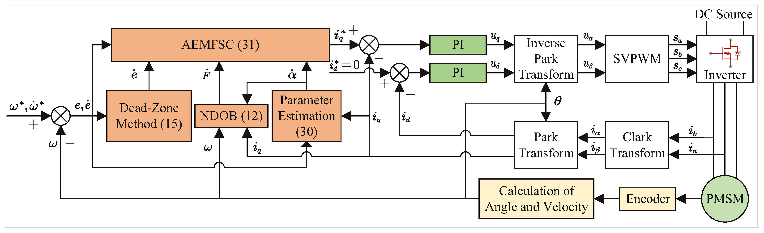
In this section, an adaptive enhanced model-free speed control framework based on the ultra-local model is developed. First, a nonlinear disturbance observer (NDOB)-enhanced model-free controller (EMFSC-NDOB) is developed by integrating a nonlinear disturbance observer with proportional–derivative (PD) control architecture. Subsequently, an adaptive law for the control input gain is derived via the gradient descent method, resulting in an adaptive EMFSC-NDOB method (AEMFSC-NDOB). Finally, an initial value determination method for the control input gain is derived based on algebraic differentiation techniques.
3.1. Enhanced Model-Free Speed Control via Nonlinear Disturbance Observer
In this article, according to (3), considering the SMPMSM q-axis current as the output variable, the ideal ultra-local mathematical model of SMPMSM can be expressed as
where the output
, the input
, the theoretical control gain
, and the lumped disturbance
.
The practical difficulty in obtaining accurate machine parameters leads to a parametric mismatch between the designed ultra-local model and the true system dynamics. Therefore, the practically realized ultra-local model takes the following form:
where the lumped disturbance
. With model (11) as the basis, the model-free feedback control scheme (6) is subsequently deployed. However, the existence of
results in control law (6) not being implemented. To achieve the precise and rapid real-time estimation of
, the nonlinear disturbance observer (NDOB) was designed as follows [
36]:
where
Z is an auxiliary variable,
L is the positive gain of the nonlinear disturbance observer, and
is the estimated value of the lumped disturbance.
Taking the derivative of the observer error
and using (11) then yields
Considering that the total disturbance and are bounded, where , according to the principle of Lyapunov function stability, the nonlinear disturbance observer system is progressively stable.
To enhance the transient tracking performance of the speed control system, a PD control law was employed to ensure the convergence of the tracking error. Therefore, the enhanced model-free controller is proposed as
where
are the control parameters.
To prevent the amplification of high-frequency noise in the speed-tracking error differentiation, which may cause control signal chattering and potential system instability, a dead-zone method was implemented in the controller. This approach suspends the error derivative calculation when the error magnitude falls below a predefined threshold. Specifically, the dead-zone implementation is as follows:
where
is the error threshold.
Substituting the control law (14) into the tracking error dynamics (5) based on (10), one has the following error equation:
where
,
, and the residual disturbance
. Then, rewriting the above equation gives the following:
where
The Lyapunov function is defined as
, where
denotes a positive real number. Taking the derivative of
V, it yields
where
represents the upper bound of
. Obviously, when
,
can be guaranteed. Furthermore, one gets
Thus, the closed-loop system is asymptotically stable, and the tracking error is uniformly ultimately bounded.
3.2. Adaptive Enhanced Model-Free Speed Controller Design
The gain critically determines both the closed-loop stability and speed regulation quality in PMSM drives. This work proposes a gradient-descent-based online auto-tuning scheme to optimize this essential parameter.
The above (11) can be discretized as follows:
where
is the sampling time. Since the change period of the lumped disturbance
is much larger than the period of the sampling time
, it can be considered that the lumped disturbance is unchanged in the adjacent sampling period, namely,
On this basis, we have
with
.
Then, the output error can be expressed as
Define the following cost function:
Therefore, the gradient of the cost function with respect to
is given by
The presence of the measurement noise
in the error signal
can corrupt the gradient estimation, causing the parameter
to oscillate randomly around or deviate cumulatively from its true value. To enhance the adaptation law, a dead-zone technique was introduced to suppress noise effects by disabling updates during small-error conditions. The implementation details are as follows:
where
is the error threshold. Therefore, the update law for
is given as follows:
where
is the learning rate.
To prevent instability in the parameter adaptation caused by excessively large or small control inputs
, a nonlinear modulation scheme was applied to the learning rate. The learning rate
is dynamically adjusted based on the input variation
, as specified below:
By incorporating this nonlinear modulation scheme into the standard gradient update law, the final adaptation rule can be gotten using
where
is the adaptive coefficient, and
is the initial value of
.
Combining the nonlinear disturbance observer (12), enhanced model-free speed control law (14), and adaptive gain law (30) based on the gradient descent method, the final adaptive enhanced model-free speed controller (AEMFSC) was designed to be
The block diagram of the proposed PMSM speed control strategy is shown in
Figure 1.
3.3. Initial Value Estimation Method for the Input Gain
In practical motor applications, two major challenges exist: (1) inaccuracies or missing specifications of flux linkage parameters and torque coefficients on nameplates, and (2) considerable difficulties in accurately estimating the moment of inertia under complex loading conditions, resulting in significant deviations between the calculated and actual values.
For constant-load motor systems, employing a fixed value effectively reduces the computational overhead in embedded systems. For variable-load systems, appropriate initial values substantially enhance the transient tracking performance during the startup phase. This subsection consequently presents an algebraic-framework-based linear identification method for high-precision identification.
The electromechanical Equation (3) of the SMPMSM drive system can be expressed as
where
is the rotor mechanical angle,
,
,
, and
. The constant parameters
are unknown, and the
is considered to be a constant load perturbation [
37]. Then (32) in the
S-domain is given as
where
is an arbitrary initial angle and
is an unknown initial velocity.
Introduce a first-order low-pass filter given by
where the known constant parameter
is strictly positive. Thus
Multiplying both sides of (35) by
s yields
Deriving both sides three times with respect to
s in order to eliminate the unknown parameter
and the initial conditions
and
:
Then multiplying both sides by
to avoid derivations with respect to time:
The remaining negative powers of
s correspond to iterated time integrals. The corresponding formulae in the time domain are easily deduced thanks to the correspondence between
, and the multiplication by
in the time domain. Equation (38) in time domain can be obtained as
with
We have denoted by
the quantity
. Moreover,
.
Integrating the expression (40) one time leads to the following system of linear equations for the estimates
and
of unknown parameters:
with
By applying Fubini’s theorem to reduce the multiple integral to a single integral, and subsequently employing the trapezoidal integration method to discretize (41), we obtain the following discrete equation:
with
After a time interval of the form , the estimates a and b can be obtained by solving the previous expression. Then the input gain can be used in the proposed EMFSC (14) or AEMFSC (31).
4. Simulation and Experimental Results
This section conducts a rigorous comparative evaluation of the proposed EMFSC-NDOB (14) and AEMFSC-NDOB (31), comparing them with two control methods: conventional MFSC-API [
28] and MFSC-NDOB (7). The assessment examines transient response, steady-state accuracy, and disturbance rejection capabilities under identical operating conditions.
Simulation and experimental studies were conducted on the SMPMSM drive system using a two-level voltage source inverter, with the SVPWM switching frequency, sampling rate, and current-loop control frequency all set to 10 kHz. The dead-time was set as 0.5 µs. The current loop employed a decoupled PI controller with the parameters set to
= 3 and
= 0.067. The speed loop frequency was 2 kHz.
Table 1 lists the specification of the SMPMSM used in the digital simulation and experimental tests.
The proposed EMFSC-NDOB and AEMFSC-NDOB frameworks exhibit inherent model-free characteristics and nonlinear dynamic coupling, making the analytical determination of optimal parameter combinations currently infeasible. This study adopted a trial-and-error approach coupled with numerical simulations for parameter tuning: Initially, was set to zero while was incrementally increased until critical system oscillations emerged. Subsequently, was introduced to suppress these oscillations, with the final parameter combination determined through a comprehensive evaluation of closed-loop performance metrics, including the overshoot, settling time, and steady-state error.
The proportional gain predominantly governs the system response speed and bandwidth; higher values improve the responsiveness at the cost of an increased overshoot and noise sensitivity. Conversely, the derivative gain kd effectively mitigates high-frequency oscillations and enhances the stability, though potentially introducing high-frequency noise components. To address steady-state noise amplification, a threshold was implemented, which was carefully selected to slightly exceed the observed velocity fluctuation amplitude. The adaptive gain requires careful balancing, as excessive values may induce oscillations while insufficient values result in sluggish convergence.
Within the NDOB architecture, the observer gain L critically determines the trade-off between the disturbance estimation convergence rate and the high-frequency noise sensitivity. Elevated L values accelerate the disturbance estimation but risk sensor noise amplification and the potential excitation of unmodeled high-frequency dynamics, which manifests as control input chattering. Reduced L values improve the noise robustness and stability, yet incur delayed disturbance estimation that compromises rapid disturbance rejection capability. This fundamental compromise necessitates careful optimization between the convergence speed and noise sensitivity.
4.1. Simulation Results
Numerical simulations of the PMSM speed regulation system were conducted using MATLAB/Simulink (Version R2023b), with the control algorithm executed in the discrete-time domain at a 2 kHz sampling rate. Notably, the simulation model incorporated realistic encoder quantization effects by superimposing discrete position measurement noise.
The parameters of the MFSC-API, MFSC-NDOB, EMFSC-NDOB, and AEMFSC-NDOB controllers were chosen as follows: = 160 and = 10 for the MFSC-API controller; = 400 and L = 50 for the MFSC-NDOB controller; = 400, = 1, L = 50, and = 0.3 rad/s for the EMFSC-NDOB controller; and = 400, = 1, L = 50, = 0.3 rad/s, and = 20 for the AEMFSC-NDOB controller. The reference speed was 90 rpm, and the inertia of the load was chosen as = 0.00134 kg·m2. Therefore, the theoretical value of the input gain was .
Figure 2 shows the startup responses of the MFSC-API, MFSC-NDOB, EMFSC-NDOB, and AEMFSC-NDOB controllers at the reference speed of 90 rpm. The load torque was initially set to zero, so the PMSM could be assumed to be load-free.
Figure 2 clearly demonstrates that both the EMFSC-NDOB and AEMFSC-NDOB controllers exhibited superior dynamic performances, where they achieved minimal overshoots and the fastest settling times among all the compared methods. However, when the selected input gain and the theoretical true input gain was mismatched, the performance of the PMSM system deteriorated.
Figure 3 presents a comparative analysis of the disturbance rejection capabilities among the four control schemes. The results demonstrate that the proposed AEMFSC-NDOB controller exhibited superior load disturbance rejection, with a merely 18.4% speed drop during the sudden load torque application (4.0 N·m step change at t = 0.25s) compared with 25.7% for the MFSC-NDOB method. Furthermore, the parameter mismatch analysis revealed that the input gain variations could degrade the system’s disturbance rejection performance.
Figure 2 and
Figure 3 demonstrate that variations in the system input gain
induced corresponding changes in the steady-state value of the observer-estimated lumped disturbance
. This phenomenon stems from the composite nature of
F, which encompasses unmodeled dynamics, external disturbances, and nonlinearities. Crucially, the disturbance estimation
depends on the input gain
rather than the true value
. When the observer computes disturbances using an inaccurate
, it systematically misattributes the control input effects (resulting from the
mismatch) as part of the disturbance. In the ULM framework,
F represents a coupled quantity that combines both the
-related terms and true disturbances. Consequently, an
mismatch compromises the decoupling process, causing
to deviate from the actual disturbance characteristics.
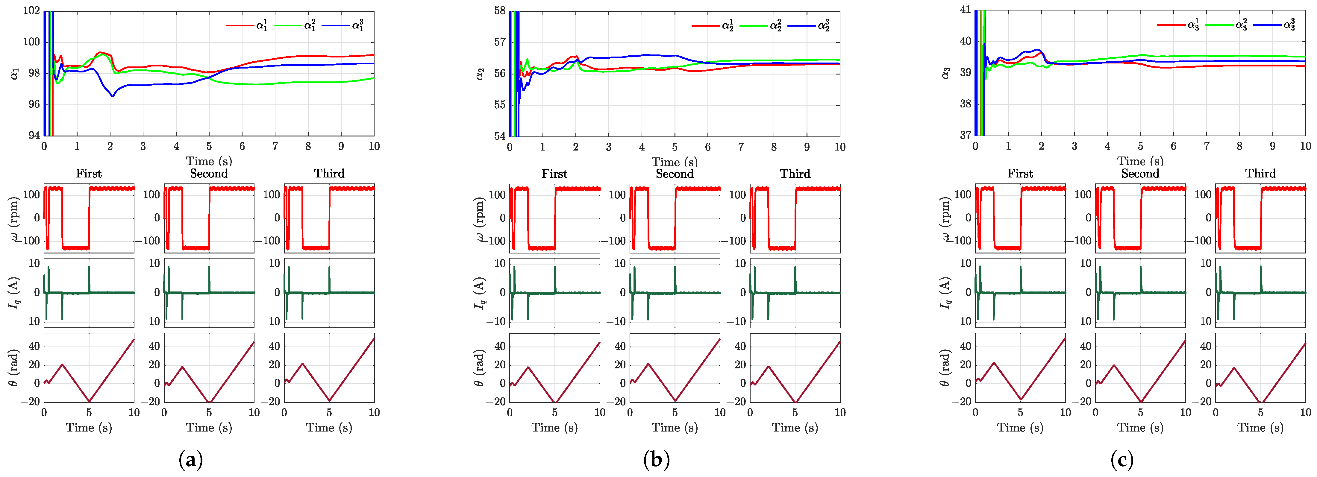
To validate the effectiveness of the
adaptation algorithm, three distinct initial value conditions were experimentally tested. As demonstrated in
Figure 4, the results show that (i) the estimated input gain converged to its theoretical actual value within several square-wave cycles, and (ii) the automatic adjustment of the parameter
significantly reduced transient tracking errors.
The preceding analysis reveals that while the proposed AEMFSC-NDOB demonstrates exceptional robustness and rapid tracking performance, inappropriate initial values of
can adversely affect transient tracking during the startup and potentially destabilize the system. To obtain accurate
values, the algebraic-framework-based linear identification method was employed for precise input gain estimation. The estimation procedure, validated under three distinct load inertia conditions (
), operated as follows: (a) initialize with an overestimated
value (e.g.,
= 1000); (b) execute maximum-speed square-wave rotation; (c) compute
via (41) using the measured position and q-axis current.
Figure 5 confirms the high estimation accuracy across all the test cases. Notably, this computationally intensive method may require offline implementation on resource-constrained DSPs after data acquisition.
4.2. Experimental Results
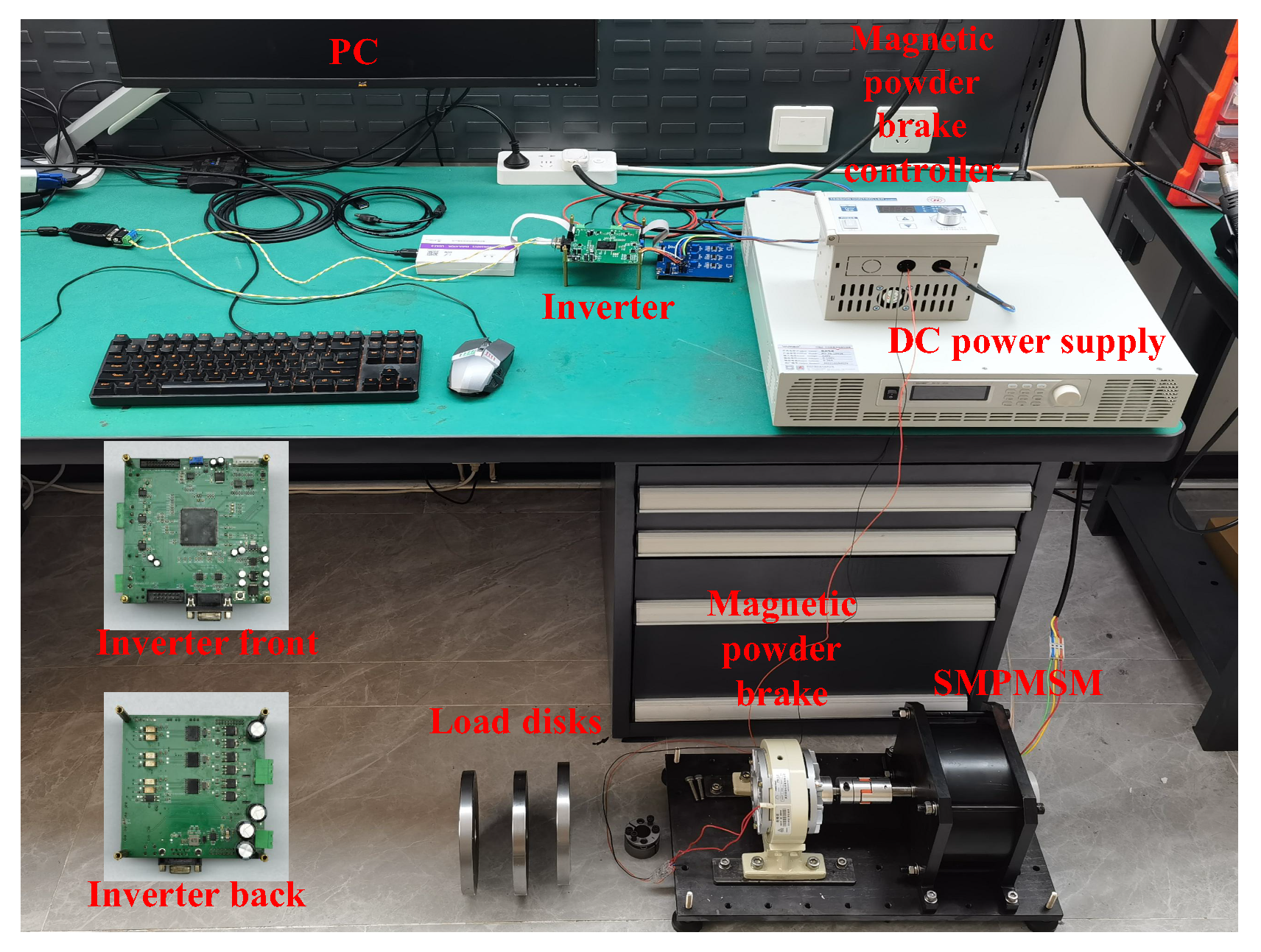
To further verify the effectiveness of the proposed control scheme, some real-time experiments were carried out.
Figure 6 depicts the experimental test platform, which was governed by a TMS320F28379D digital signal processor (DSP). The control circuit was composed of a power supply (RU-36-10036), SPMSM (J155LWX001), two-level inverter, and measurement circuit.
A MOSFET module inverter was fed by a programmable DC power supply set at 34 V in the experiments. The rotor position sensor was a 19-bit electromagnetic encoder (EAB42-0M19S-8-B) and the current sensor was a CC6920B-10A current sensor. The nominal parameters of the motor, the sampling time, and all the parameters of the current controller were the same as in the simulation.
To mitigate the sensor noise amplification and prevent motor oscillations, the practical controller implementations employed smaller parameter values compared with the simulation environments. The parameters of the MFSC-API, MFSC-NDOB, EMFSC-NDOB, and AEMFSC-NDOB controllers were chosen as follows: = 80 and = 10 for the MFSC-API controller; = 300 and L = 50 for the MFSC-NDOB controller; = 300, = 1, L = 50, and = 0.3 rad/s for the EMFSC-NDOB controller; and = 300, = 1, L = 50, = 0.3 rad/s, and = 10 for the AEMFSC-NDOB controller.
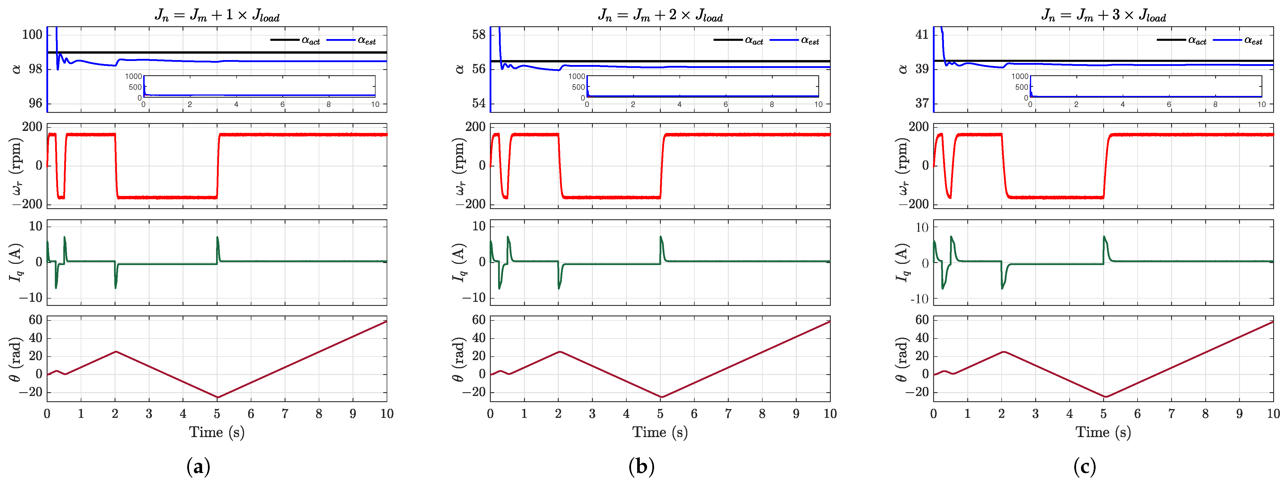
For systems with an uncertain load inertia and motor parameters, an algebraic-framework-based linear identification method can be employed to achieve precise identification of the input gain.
Figure 7 displays the estimation results of the parameter
derived from three experimental trials under distinct load conditions. The initial angle position of the motor was different each time. The inertia of each load disk was
. The estimated values exhibited remarkable consistency across all the trials, which aligned closely with the simulation outcomes. This agreement further validated the efficacy of the algebraic-framework-based linear estimation method in accurately determining the input gain parameter
. The estimated gain value can be directly employed as the fixed parameter
in the EMFSC-NDOB approach or serve as the initial value for
in the adaptive AEMFSC-NDOB scheme.
Applying the aforementioned algebraic-framework-based linear identification method, the input gain was identified as
= 300 when the load was a magnetic powder brake.
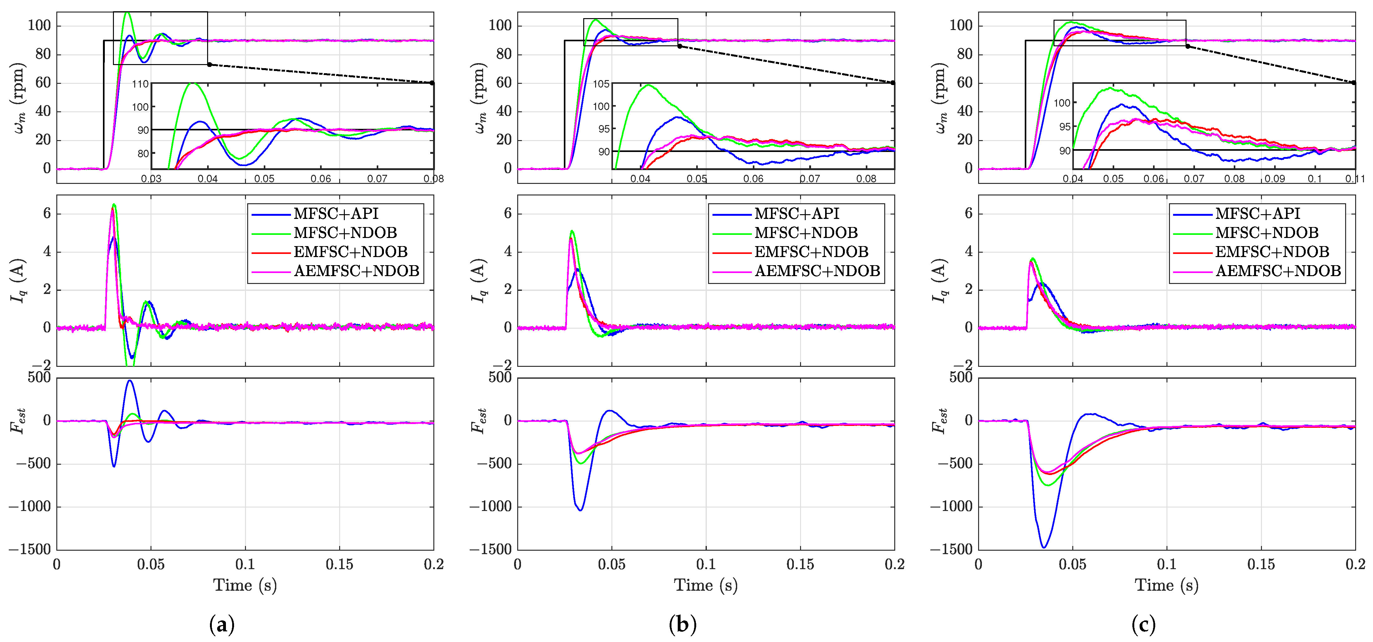
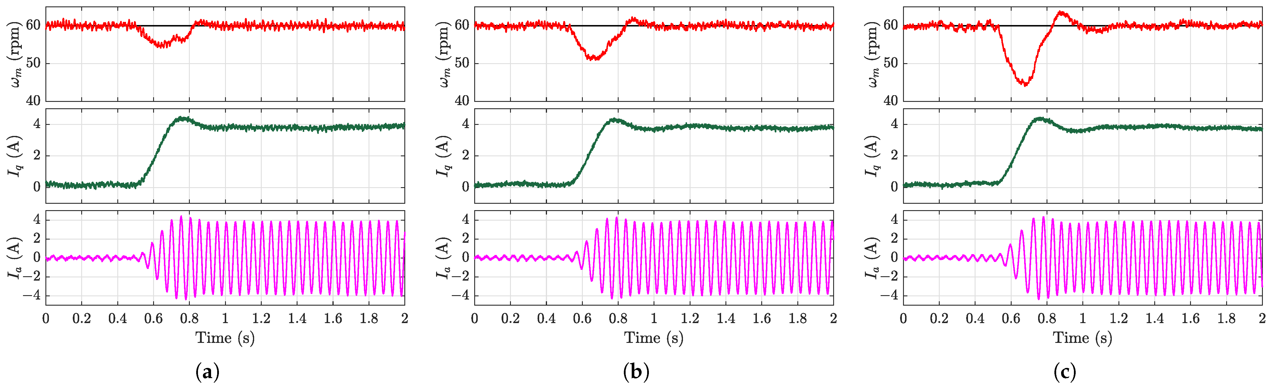
Figure 8 compares the startup responses of the MFSC-API, MFSC-NDOB, EMFSC-NDOB, and AEMFSC-NDOB controllers under no-load conditions at a 60 rpm reference speed. As demonstrated in
Figure 8a, with accurate input gain, the proposed EMFSC-NDOB and AEMFSC-NDOB controllers exhibited superior transient performances. Although the MFSC-API controller generated lower q-axis current peaks, it had a longer settling time. These results conclusively establish the advantages of the EMFSC-NDOB and AEMFSC-NDOB controllers in PMSM speed transient regulation.
Figure 8b,c reveal significant sensitivity to the input gain variations. When
, both the EMFSC-NDOB and AEMFSC-NDOB exhibited excessive speed overshoots, while the MFSC-NDOB showed a relative improvement. Notably, the elevated gain values universally prolonged the settling time across all four controllers, potentially degrading the system performance during rapid speed transitions.
Table 2 quantitatively compares the key performance indicators: (i) speed overshoot and (ii) settling time, further validating the proposed controllers’ robustness against parameter mismatches.
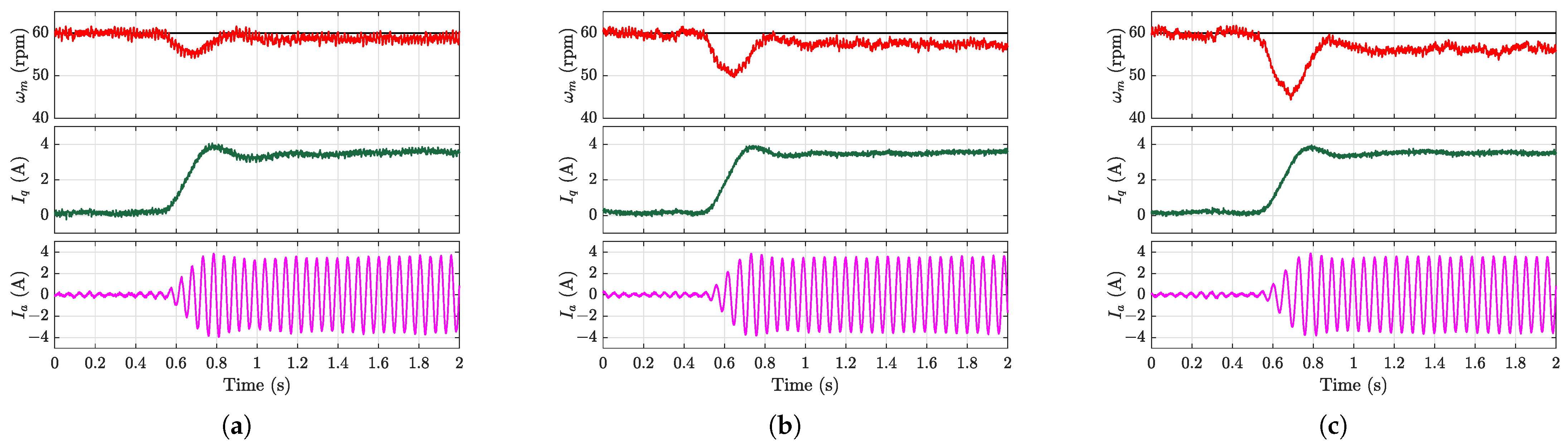
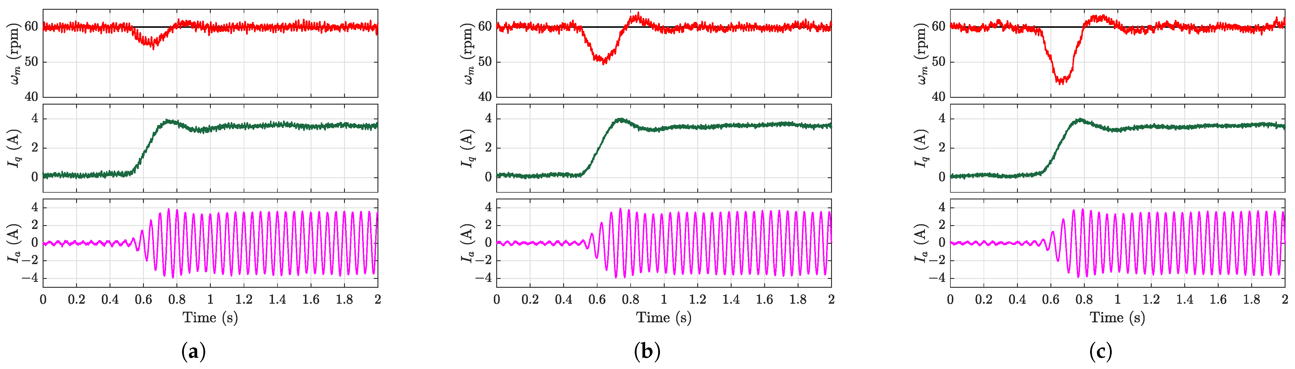
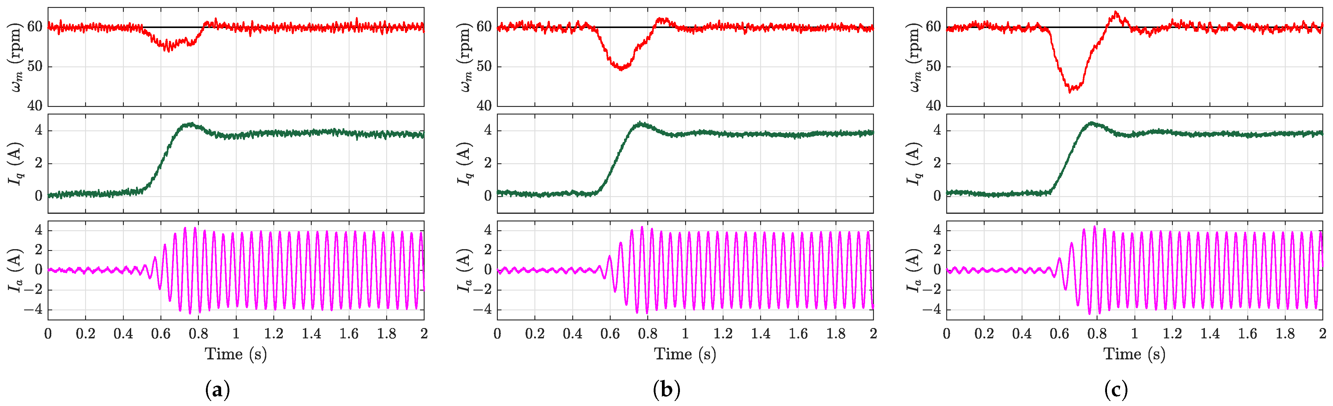
The disturbance rejection capability was evaluated during steady-state operation at 60 rpm by applying an 8 N·m load torque disturbance.
Figure 9,
Figure 10,
Figure 11 and
Figure 12 present the experimental results under this loading condition. As revealed in
Figure 9a, while the MFSC-API controller exhibited smaller speed drops, it suffered from significant steady-state errors that degraded the control performance. The comparative results in
Figure 10a–
Figure 12a demonstrate that the proposed EMFSC-NDOB and AEMFSC-NDOB schemes achieved superior disturbance rejection compared with the MFSC-NDOB. The comparison between the MFSC-API and MFSC-NDOB further reveals inherent limitations of the algebraic parameter identification approach in estimating lumped disturbances during abrupt load changes.
The experimental results with different input gain values (
and
) show substantially increased speed deviations and prolonged settling times. This confirms that the excessive input gain values severely deteriorated the system’s disturbance rejection capability. In this scenario, the proposed AEMFSC-NDOB control strategy consistently outperformed both the MFSC-NDOB and EMFSC-NDOB approaches. This superiority stemmed from its adaptive
adjustment capability during the load transients, which actively enhanced the disturbance rejection performance. It should be noted that when the controller input satisfied the persistent excitation condition, the AEMFSC-NDOB could recover its nominal anti-disturbance performance through
adaptation, even with an initial parameter mismatch. Quantitative performance metrics under load torque variations are systematically compared in
Table 3.
Figure 13,
Figure 14,
Figure 15 and
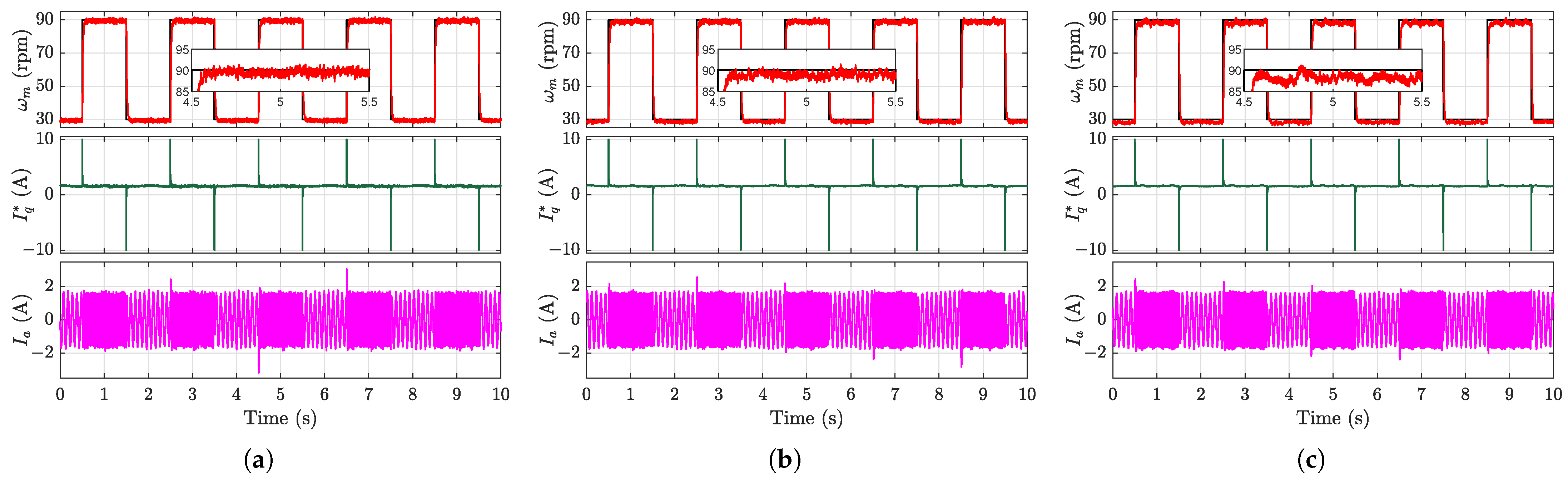
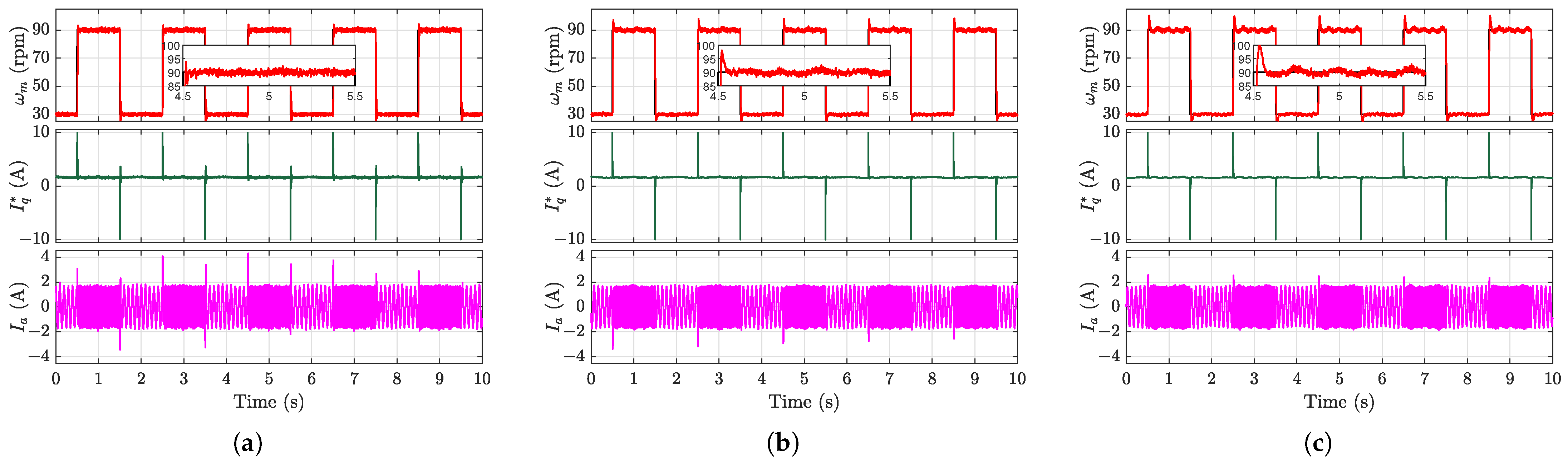
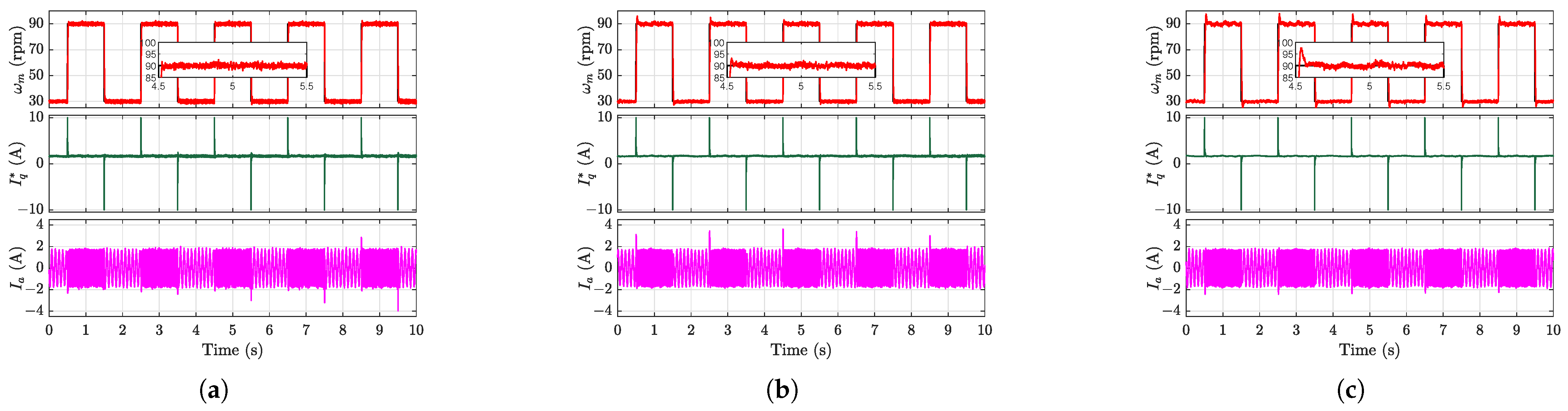
Figure 16 present the square-wave speed-tracking performance under a 4 N·m load torque, with reference speeds that ranged from 30 to 90 rpm. While the conventional MFSC-API controller exhibited steady-state errors as previously analyzed, the other three controllers achieved rapid and accurate speed tracking. However, elevated input gain values were observed to degrade the tracking performance, particularly during square-wave transitions.
Quantitative evaluations using the Root Mean Square Value (RMSE, entire process) and Integral Absolute Error (IAE, steady-state phase) metrics are summarized in
Table 4. With matched
values, the EMFSC-NDOB strategy demonstrated a superior tracking accuracy and steady-state performance. Under parameter mismatch conditions, the AEMFSC-NDOB’s adaptive mechanism effectively suppressed the speed overshoot and maintained a better high-speed tracking performance owing to its self-tuning capability.
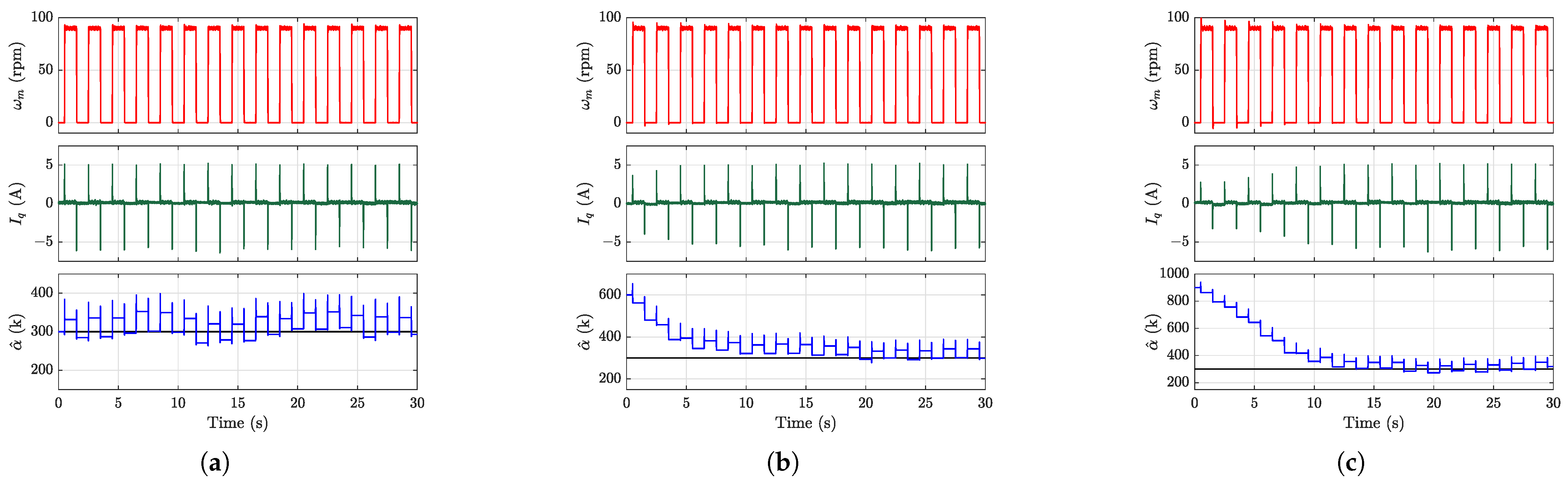
The effectiveness of the proposed
-adaptation algorithm was validated through three distinct initial conditions, with the experimental results presented in
Figure 17. The data demonstrate that the estimated
converged to the vicinity of its true value within several square-wave cycles. It should be noted that choosing a smaller value of
will reduce the oscillation amplitude of the input gain, but this comes at the cost of a longer convergence time.


