
Evaluation of Load-Bearing Performance and Cost Efficiency in Steel-Welded and Modular Aluminum Rack Structures


Abstract
1. Introduction
2. Methodology and Results
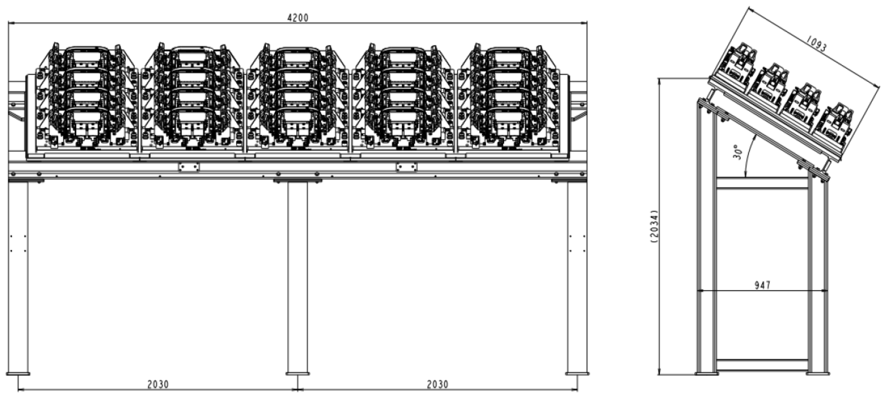
2.1. Assignment Presentation
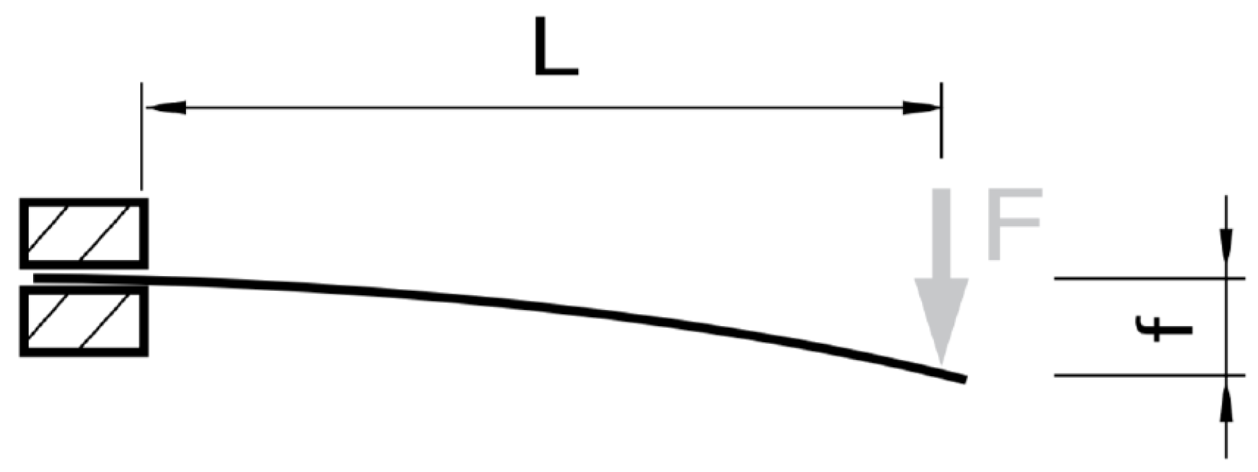
2.2. Dimensioning and Strength Material Analysis
3. Assembled Rack Structure
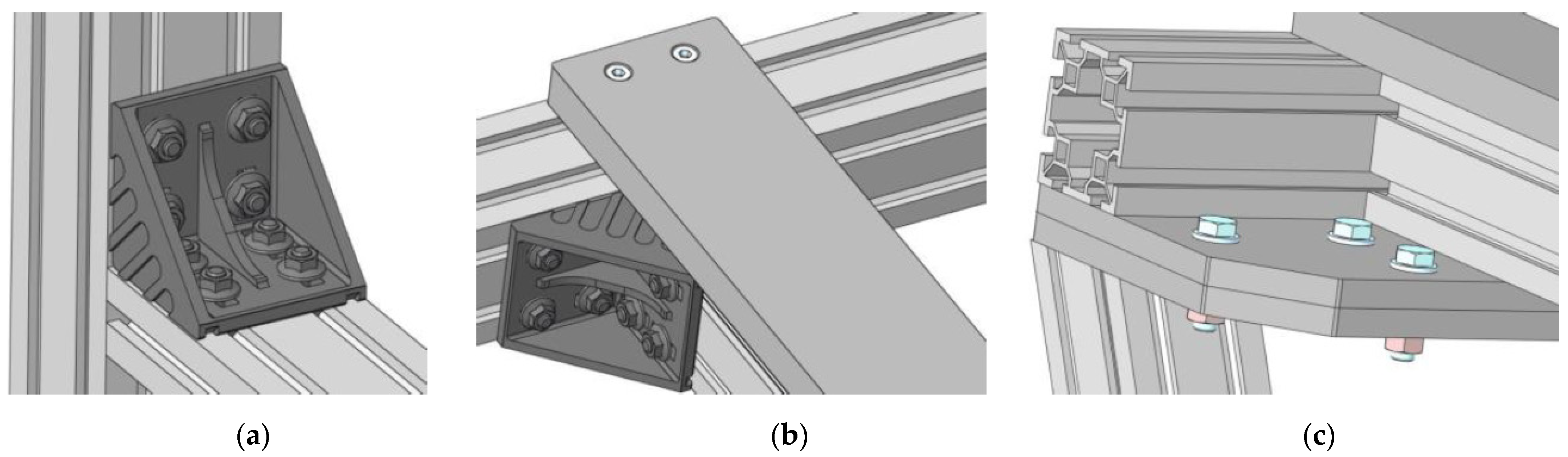
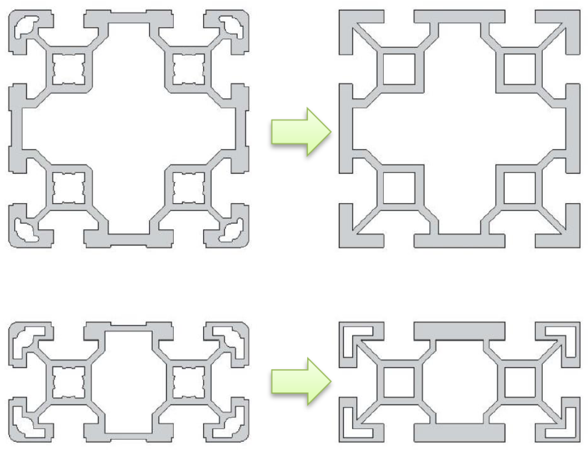
3.1. Design of an Alternative Structure Made of Aluminum Bosch Profiles
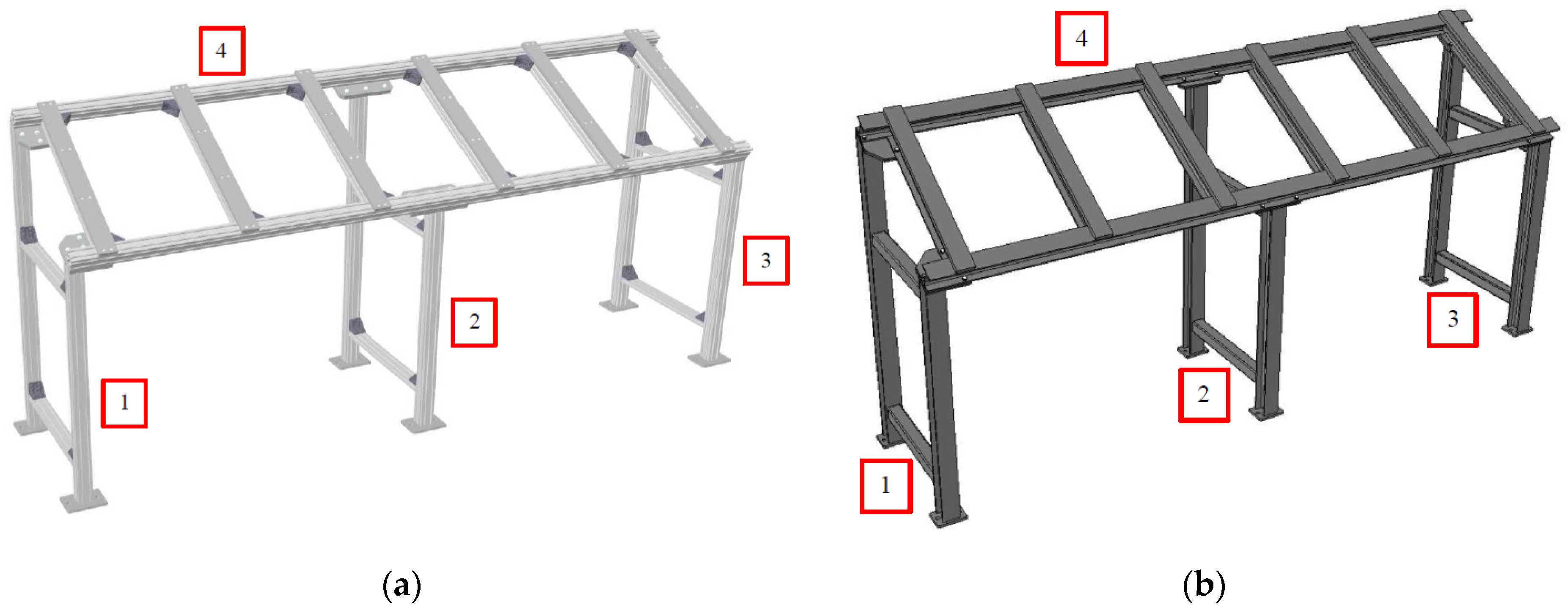
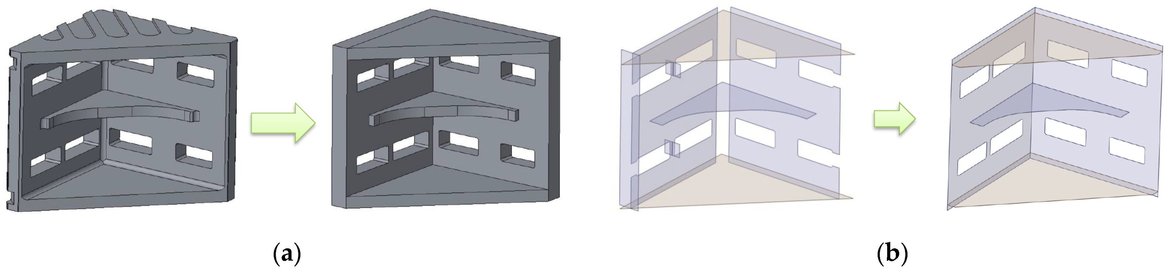
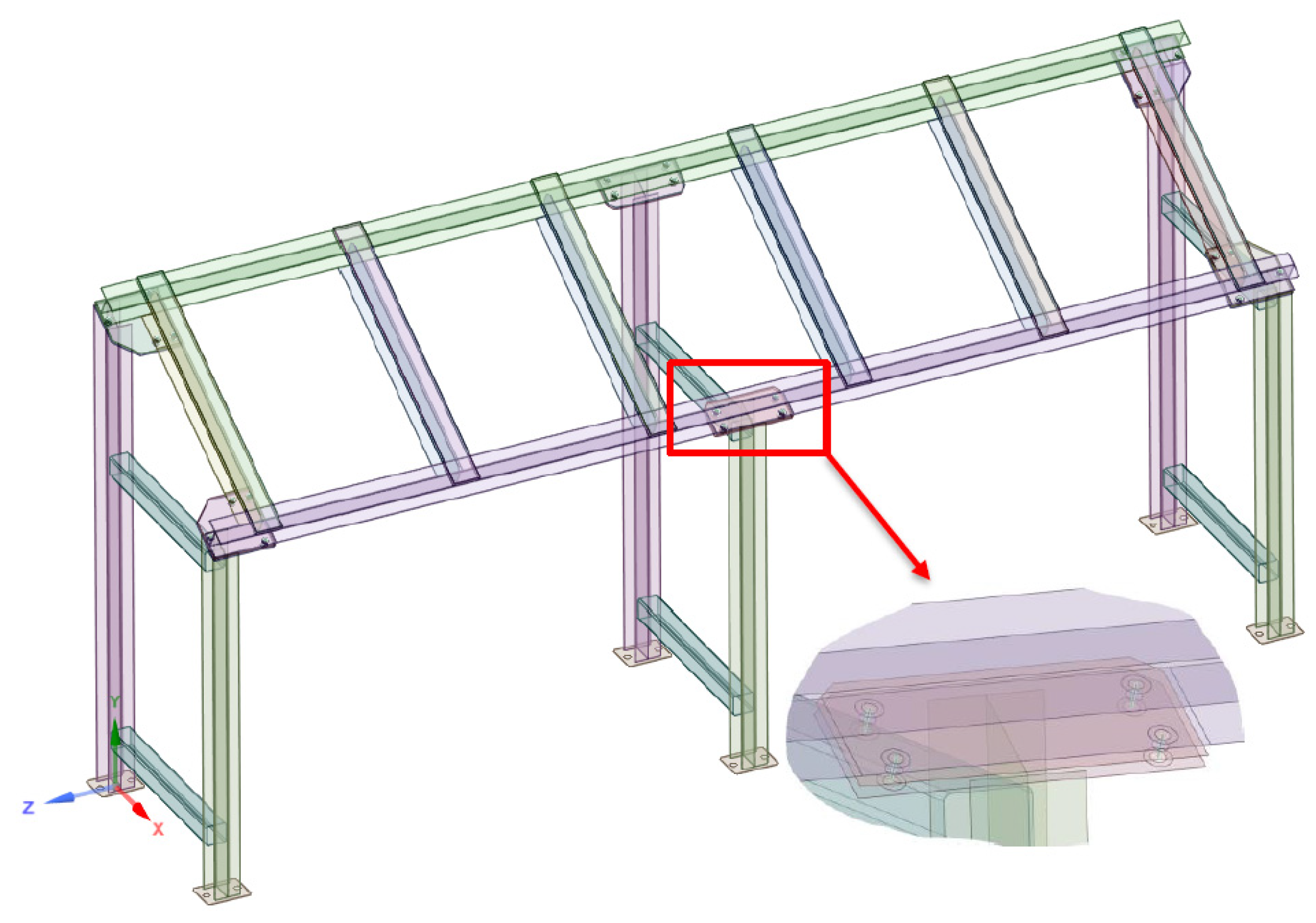
3.2. Structural Model Made of Aluminum Profiles
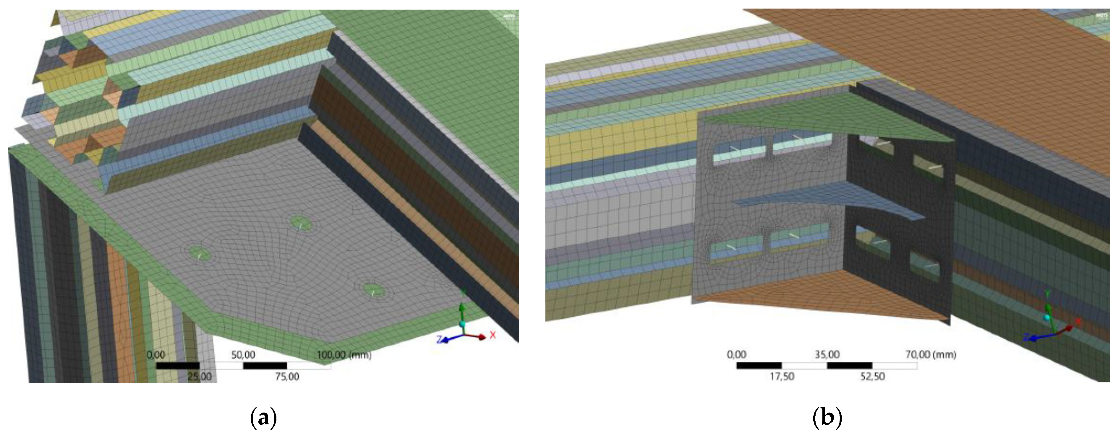
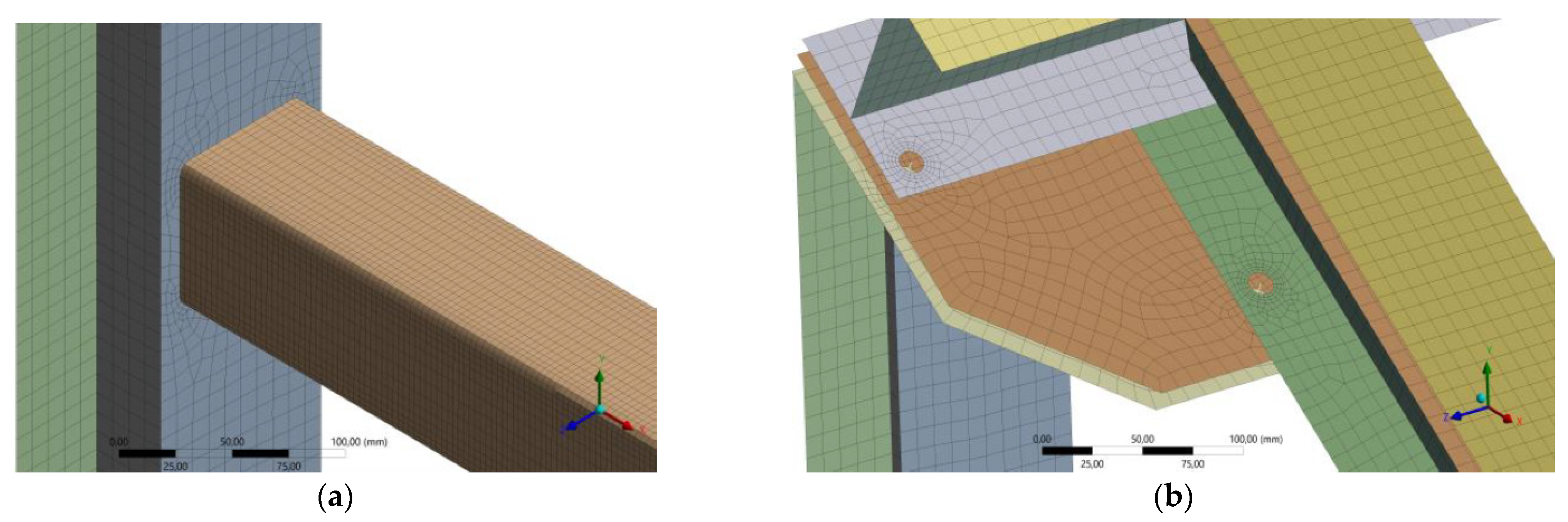
3.3. Finite Element Model of Aluminum Profiles
3.4. Boundary Conditions and Loading of the Aluminum Profile Structure
- 1.
- Hexagonal screws M14: connecting the storage to the uprights, Mk = 90 N·m. The resulting axial force is
- 2.
- Screws with a cylindrical head M8: connecting the top plates and the bottom seat plates to the storage frame, Mk = 8 N·m. The manufacturer specifies the maximum force = 7000 N. The resulting axial force will be
- 3.
- Flanged screws M8: used in brackets, connecting the profiles, Mk = 8 N·m. Even though the same tightening torque is used as in the previous case, the screws have a larger seating area due to the different shape of the head, resulting in a lower axial force:
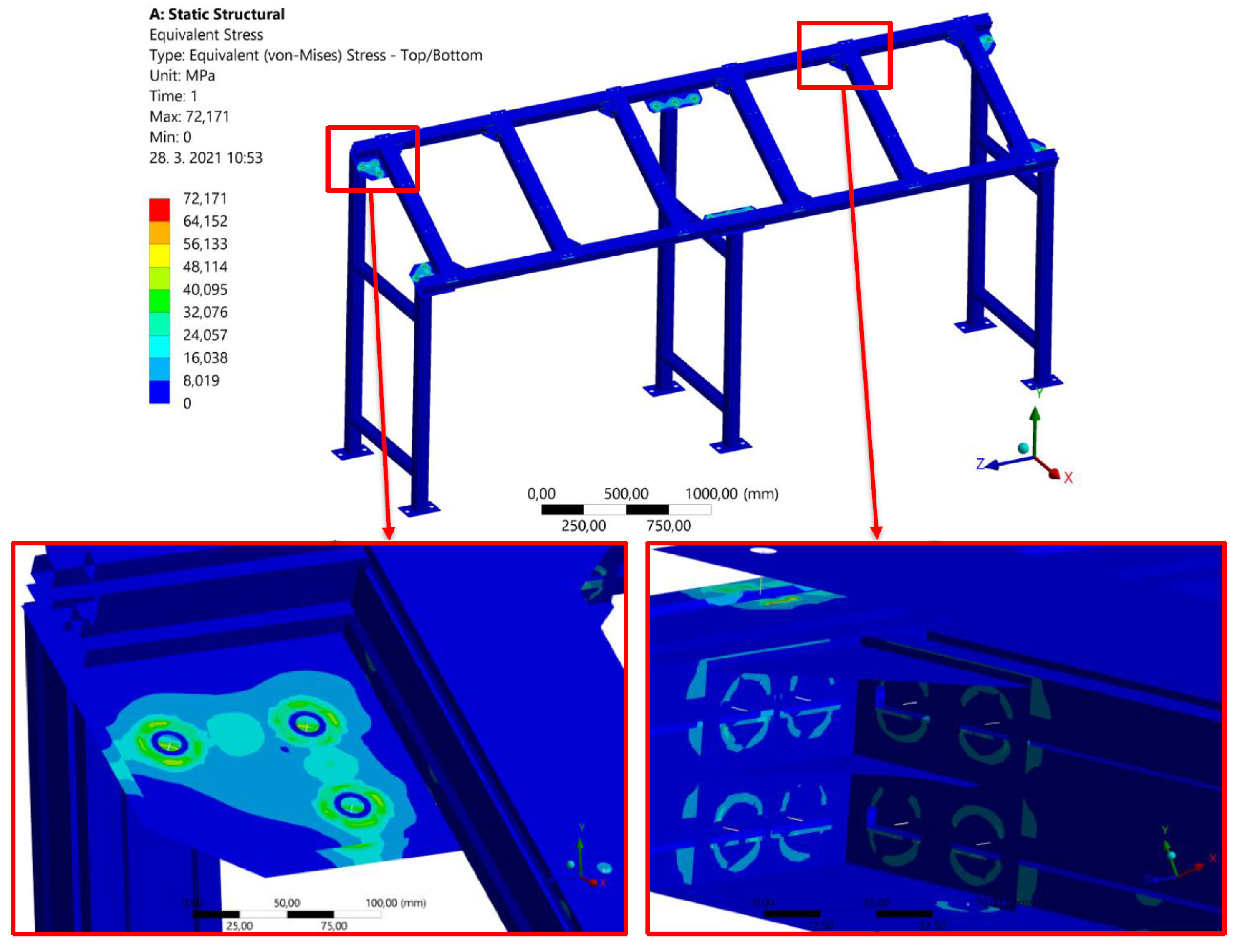
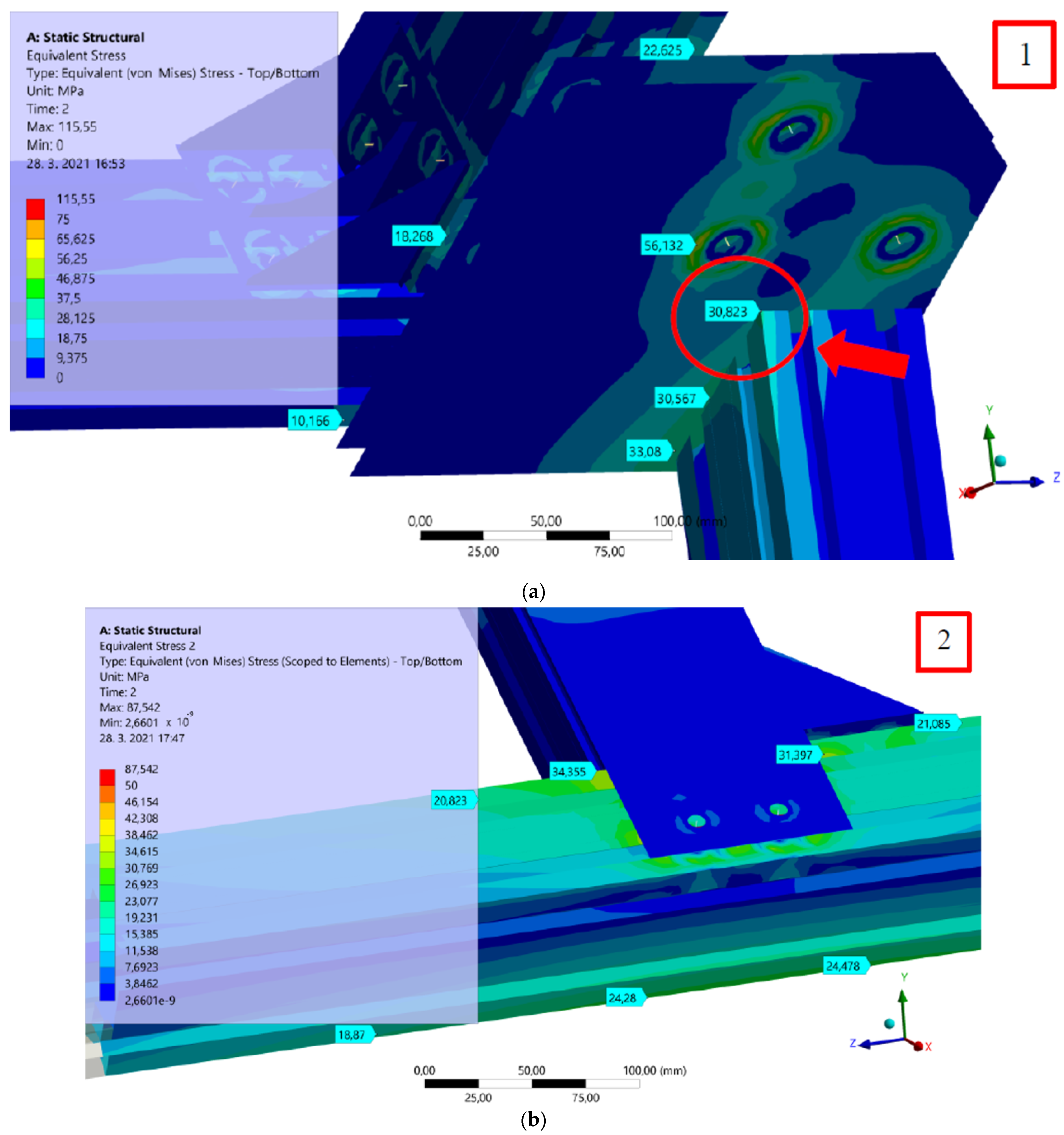
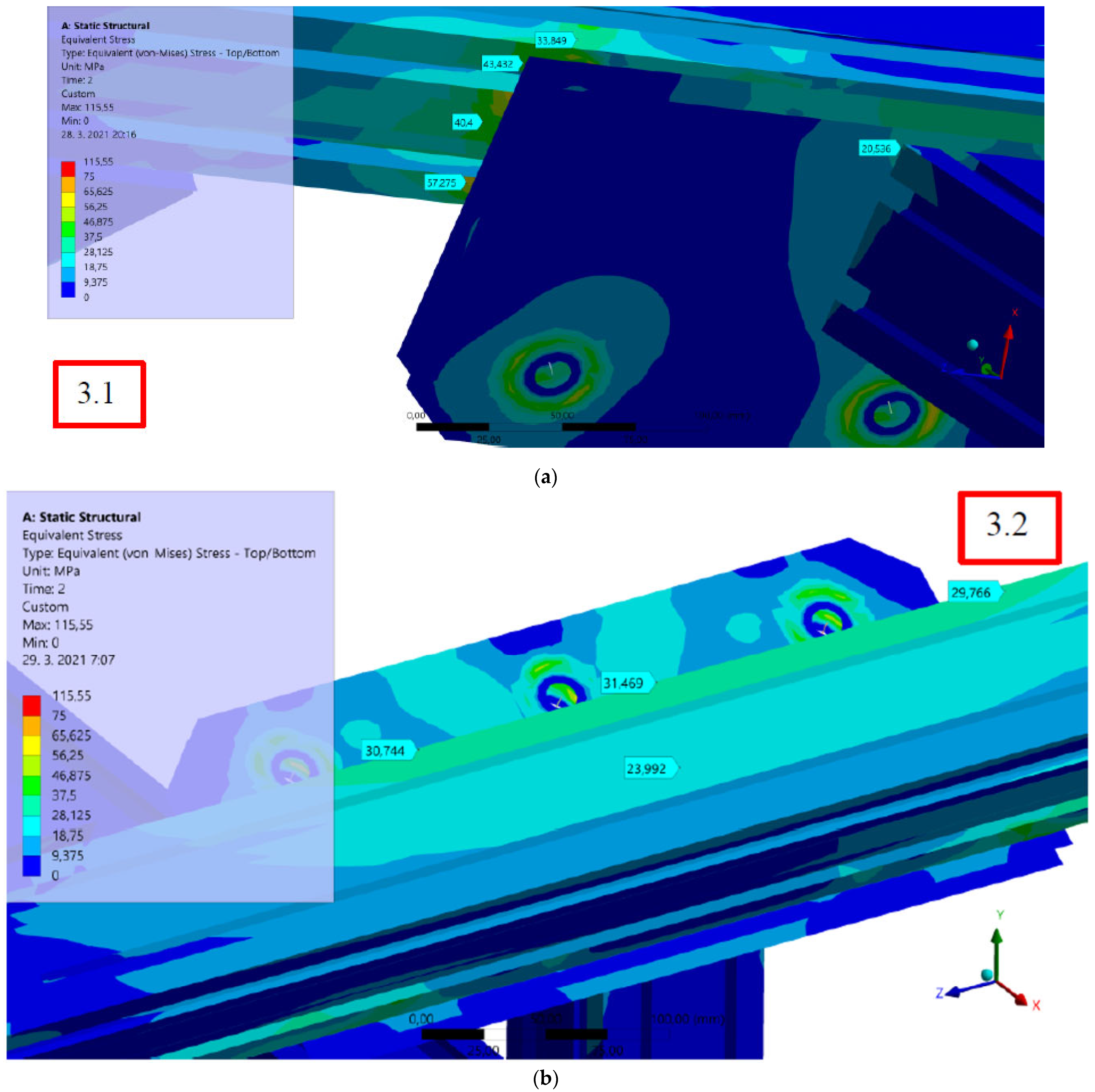
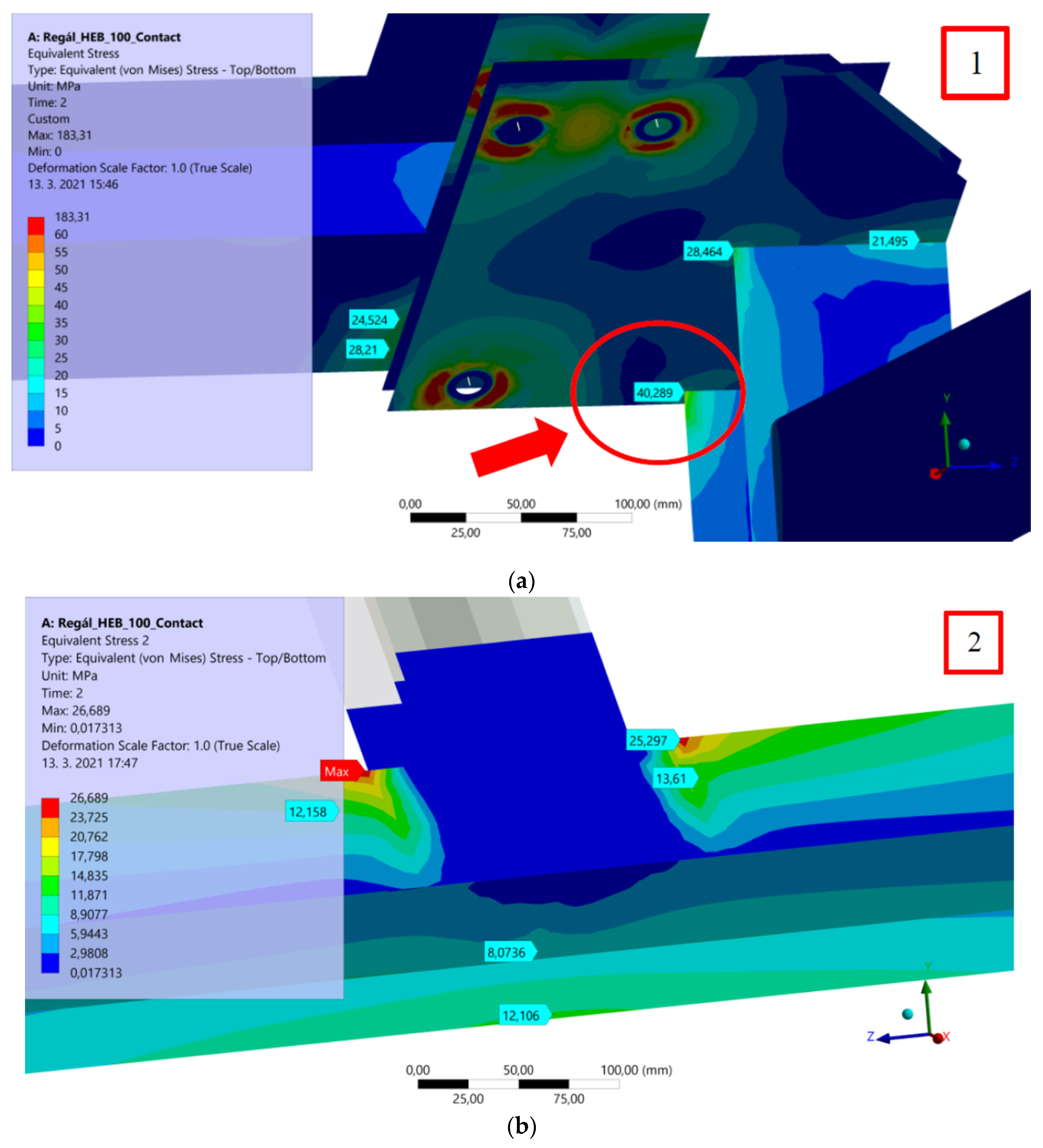
3.5. Results of the Structural Strength Analysis of the Aluminum Profile
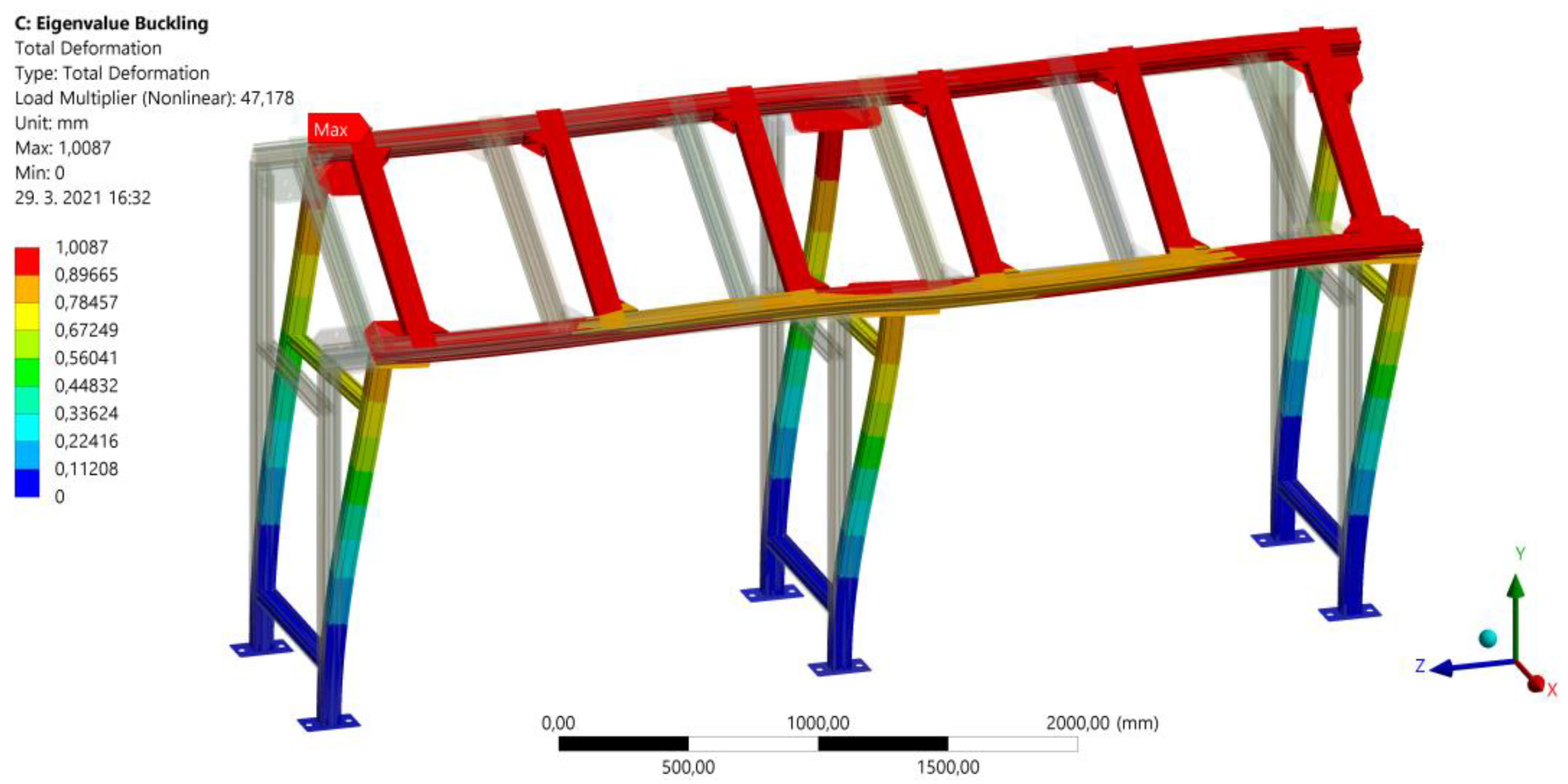
3.6. Eigenvalue Buckling (Boss of Stability) of the Aluminum Profile
4. Welded Rack Structure
4.1. Structural Model of the Welded Construction
4.2. Finite Element Shell Model of the Welded Structure
4.3. Boundary Conditions and Loading of the Welded Structure
- Considering the significant weight of the storage, the structure was loaded with its own weight using the “standard earth gravity” function. In the first step, bolt pretension was applied to all bolted joints in the structure using the “bolt pretension” function, which arises due to tightening the joints with a torque wrench. In this case, the known torque value Mk = 70 N·m applied during the tightening of the bolts is used, and the axial force in the bolt is calculated using the formula: [47]
- In the next step, a continuous load of force with a magnitude of F = 30,000 N, acting in the direction of gravity, was applied to the surfaces of the upper plates. This force includes primarily the weight of the welding fixtures when the rack is fully loaded, along with the weight of other structural elements placed on the rack for securing the fixtures (cover plates, seating plates with encoding for recognizing the presence of a specific fixture type, etc.) (Figure 18).
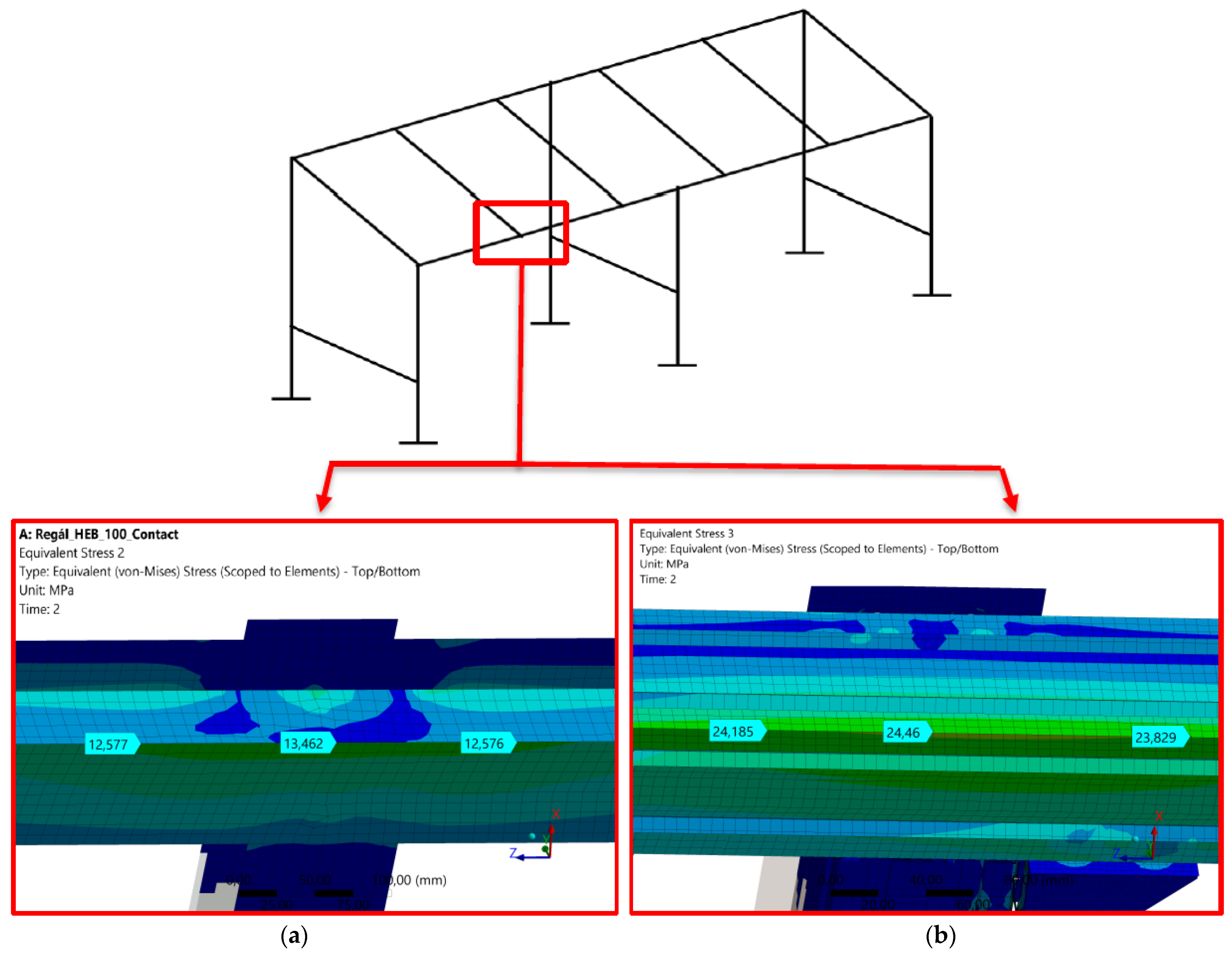
4.4. Results of the Strength Analysis of the Welded Structure
4.5. Eigenvalue Buckling (Loss of Stability) of the Welded Structure
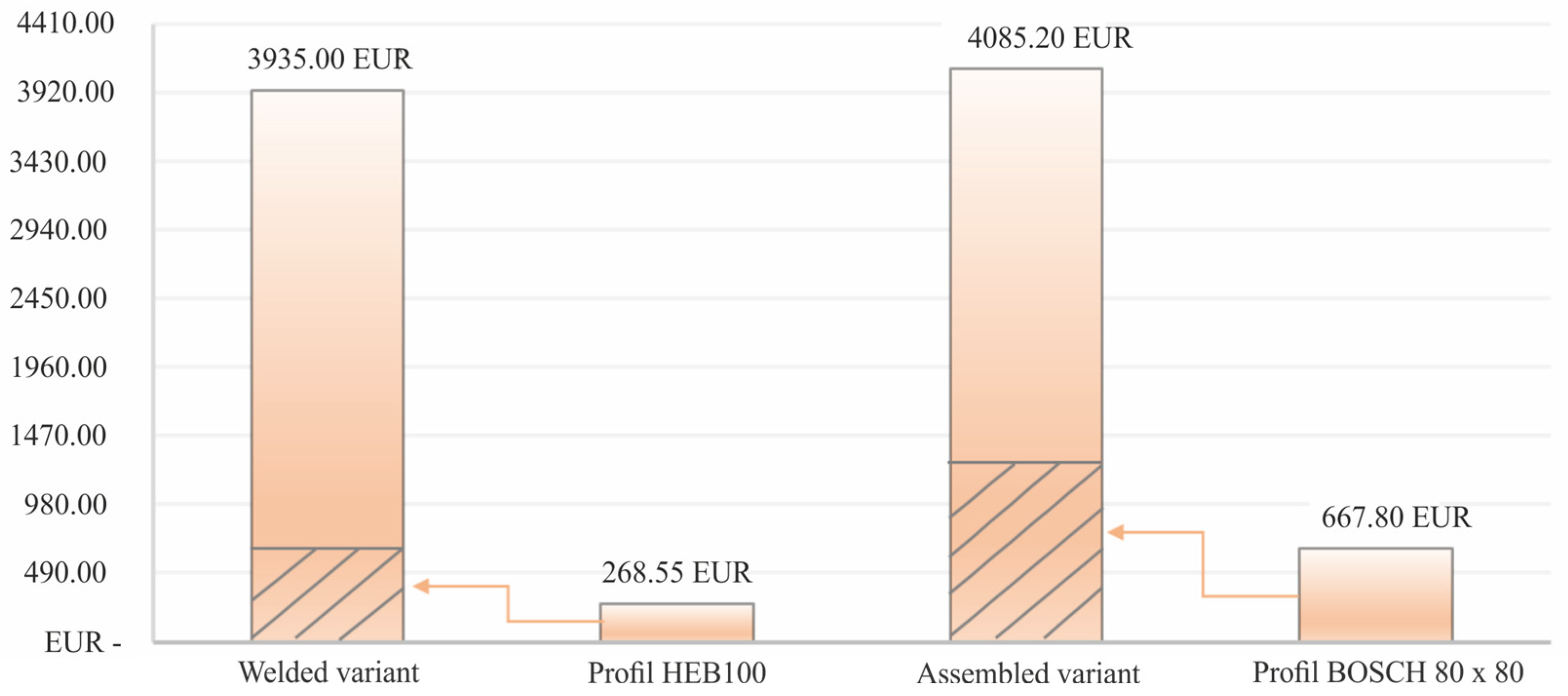
5. Cost Comparison from an Economic Perspective
- (a)
- Assembled variant
- Input materials (Bosch profiles, plates, and fastening materials—bolts, angle brackets, T-nuts);
- Cutting profiles to the required dimensions;
- Welding of the structure;
- Milling parts of the structure—drilling cylindrical recesses into plates for bolts with a cylindrical head;
- Assembly of the structure.
- (b)
- Welded variant
- Input materials (I profiles, Jäkl profiles, plates, and fastening materials—bolts);
- Cutting of semi-finished products to the required dimensions;
- Welding of the structure;
- Milling parts of the structure—the storage (adjusting the top plates and drilling mounting holes);
- Spraying the structure;
- Assembly of the structure.
6. Comprehensive Comparison of Variants and Discussion of the Obtained Results
7. Conclusions
Author Contributions
Funding
Data Availability Statement
Conflicts of Interest
References
- Huang, J.; Arinez, J. Modeling and Dynamic Assignment of the Adaptive Buffer Spaces in Serial Production Lines. J. Manuf. Sci. Eng. 2021, 143, 031005. [Google Scholar] [CrossRef]
- Benito, R.; Hurtado, S.; Miguel, P.; Carazas, G. Optimization of the Stacking Process of Wire Mesh Coils in Industrial Processors. In Proceedings of the 5th International Conference of the Industrial Engineering and Industrial Management (IEIM), Nice, France, 10–12 January 2024; Volume 2070, pp. 100–111. [Google Scholar] [CrossRef]
- Loske, D.; Koreis, J.; Klumpp, M. Golden Zone Storage Assignment and Picking Performance: An Empirical Analysis of Manual Picker-to-Parts OP Systems in Grocery Retailing. IFAC-PapersOnLine 2022, 55, 508–513. [Google Scholar] [CrossRef]
- Molina, E.; Horvath, L.; West, R. Development of a Friction-Driven Finite Element Model to Simulate the Load Bridging Effect of Unit Loads Stored in Warehouse Racks. Appl. Sci. 2021, 11, 3029. [Google Scholar] [CrossRef]
- Ozkal, F. Effects of Steel Bolts on Retrofitting the Buckling Performance of Storage Rack System Uprights. Structures 2024, 64, 106578. [Google Scholar] [CrossRef]
- Ungermann, D.; Lemanski, T.; Brune, B.; Weiss, N.; Schulz, A.; Gosling, P. Optimized Shelving Racks through the Use of High-Strength Steel. Stahlbau 2023, 92, 495–507. [Google Scholar] [CrossRef]
- Heo, G.; Choi, G.; Baek, E.; Kim, C. Development of Viscoelastic Damper System to Improve Seismic Performance of Storage Racks. KSCE J. Civ. Eng. 2021, 25, 3390–3400. [Google Scholar] [CrossRef]
- Hu, D. Automated Pallet Racking Examination in Edge Platform Based on MobileNetV2: Towards Smart Manufacturing. J. Grid Comput. 2024, 22, 20. [Google Scholar] [CrossRef]
- Blatnicky, M.; Dizo, J.; Barta, D.; Drozdziel, P. Engineering Design and Strength Analyses of Main Load-Bearing Parts of a Mechanical Rack System. Diagnostyka 2018, 19, 97–104. [Google Scholar] [CrossRef]
- Liu, S.; Pekoz, T.; Gao, W.; Zieman, R.; Crews, J. Frame Analysis and Design of Industrial Rack Structures with Perforated Cold-Formed Steel Columns. Thin-Walled Struct. 2021, 163, 107755. [Google Scholar] [CrossRef]
- Peng, D.; Wang, Z.; Sha, C. Analysis of the Effects of Back-stayed Arrangement on the Mechanical Properties of Corbel Shelf. In Proceedings of the International Conference on Mechanical, Manufacturing, Modeling and Mechatronics (IC4M), Kuala Lumpur, Malaysia, 27–29 February 2016. [Google Scholar] [CrossRef]
- Marinopoulou, E.; Tsavdaridis, K.D.; Efthymiou, E. Modern Design Methods on Optimised Novel Aluminium Profiles. Buildings 2022, 12, 1904. [Google Scholar] [CrossRef]
- Lutomirska, M.; Lutomirski, T. A Practical Case Study on Assessment and Rehabilitation of a Pipe Rack. Eng. Fail. Anal. 2022, 141, 106654. [Google Scholar] [CrossRef]
- Faria, V.; Freitas, M.; Brandao, A. Reliability of Rack Columns Designed by the Direct Strength Method. Struct. Eng. Int. 2024, 34, 211–218. [Google Scholar] [CrossRef]
- Alvarez, O.; Maureira, N.; Nunez, E.; Sanhueza, F.; Videla, A. Numerical Study on Seismic Response of Steel Storage Racks with Roller Type Isolator. Metals 2021, 11, 158. [Google Scholar] [CrossRef]
- Mohamed, M.; Khalifa, W.; Mahmoud, M. Failure Analysis of Alloy Boron Steel Bolts in Steel Structure Assembly. J. Fail. Anal. Prev. 2022, 23, 88–98. [Google Scholar] [CrossRef]
- Ziambaev, N. Analysis of Oscillations of Framework at Pulse Influence Taking into Account Physical Non-Linearity. In Proceedings of the International Conference on Construction, Architecture and Technosphere Safety (ICCATS), Chelyabinsk, Russia, 26–28 September 2018. [Google Scholar] [CrossRef]
- Muniandy, V. Development of Racking and Irrigation System for Industrial Revolution 4.0 Vertical Farming. In Proceedings of the IEEE Conference on Technologies for Sustainability (SusTech), Virtual, 21–23 April 2022; pp. 132–135. [Google Scholar] [CrossRef]
- Zhang, W.; Yu, C.; Tong, G. Model Analysis of Steel Frame Structures Considering Interactions between Racks and the Frame. Buildings 2023, 13, 1732. [Google Scholar] [CrossRef]
- Ochrymiuk, T.; Dudda, W.; Froissart, M.; Badur, J. Principles of Stress-Strength Modelling of the Highly Thermally Loaded Materials-The Influence of an Effect of Strength Differential on the Material Effort. Materials 2022, 14, 7449. [Google Scholar] [CrossRef]
- Taranu, G.; Iacob, S.; Taranu, N. Buckling Behavior of Perforated Cold-Formed Steel Uprights: Experimental Evaluation and Comparative Assessment Using FEM, EWM, and DSM. Buildings 2025, 15, 1561. [Google Scholar] [CrossRef]
- Noonan, A.J.C.; Cameron, P.M.N.; Dofher, K.; Sukkasam, N.; Liu, T.; Rönn, L.; Monshupanee, T.; Hallam, S.J. An Automated High-Throughput Lighting System for Screening Photosynthetic Microorganisms in Plate-Based Formats. Commun. Biol. 2025, 8, 438. [Google Scholar] [CrossRef]
- Yu, Y.; Li, Y.; Xie, F.; Song, J.; Bai, Y.; Fan, Y. Design and Experiment of Key Components of an Insertion Vegetable Grafting Machine with Six Plants Synchronous. Sci. Rep. 2025, 15, 16650. [Google Scholar] [CrossRef]
- Shaker, F.M.F.; Mamdooh, Z.; Deifalla, A.; Yehia, M.M. Experimental Investigations of the Behavior of Stiffened Perforated Cold-Formed Steel Sections Subjected to Axial Compression. Buildings 2022, 12, 812. [Google Scholar] [CrossRef]
- Baek, S.; Won, J.; Jang, S. Economic Integrated Structural Framing for BIM-Based Prefabricated Mechanical, Electrical, and Plumbing Racks. Appl. Sci. 2023, 13, 3677. [Google Scholar] [CrossRef]
- Vujanac, R.; Živković, M.; Slavković, R.; Vulović, S. Steel Frame versus Rack Supported Warehouse Structures. Teh. Vjesn.—Tech. Gaz. 2017, 24, 1269–1276. [Google Scholar] [CrossRef]
- Mela, K.; Heinisuo, M. Weight and Cost Optimization of Welded High Strength Steel Beams. Eng. Struct. 2014, 79, 354–364. [Google Scholar] [CrossRef]
- Bernuzzi, C.; Pellegrino, C.; Simoncelli, M. Characterization of Existing Steel Racks via Dynamic Identification. Buildings 2021, 11, 603. [Google Scholar] [CrossRef]
- Deng, Z.; Shang, Y. Size-Dependent Finite Element Analysis of Functionally Graded Flexoelectric Shell Structures Based on Consistent Couple Stress Theory. Aerospace 2024, 11, 661. [Google Scholar] [CrossRef]
- Panchenko, S.; Gerlici, J.; Vatulia, G.; Lovska, A.; Pavliuchenkov, M.; Kravchenko, K. The Analysis of the Loading and the Strength of the FLAT RACK Removable Module with Viscoelastic Bonds in the Fittings. Appl. Sci. 2022, 13, 79. [Google Scholar] [CrossRef]
- Choi, H.; Yoon, H.; Jung, E.; Lee, D. Structural Stability Assessment for Optimal Order Picking in Box-Stacked Storage Logistics. Sensors 2025, 25, 1085. [Google Scholar] [CrossRef]
- He, M.; Guan, Z.; Hou, G.; Wang, X. A Novel Parts-to-Picker System with Buffer Racks and Access Racks in Flexible Warehousing Systems. Sustainability 2024, 16, 1388. [Google Scholar] [CrossRef]
- Saderova, J.; Rosova, A.; Sofranko, M.; Kacmary, P. Example of Warehouse System Design Based on the Principle of Logistics. Sustainability 2021, 13, 4492. [Google Scholar] [CrossRef]
- Houska, P.; Caisova, K.; Sitar, V.; Michna, S.; Alfonso, T. The Effect of Laser Welding Parameters on Aluminium PV Construction Rack Systems. Manuf. Technol. 2024, 24, 47–52. [Google Scholar] [CrossRef]
- Bove, O.; Casafont, M.; Bonada, J.; Ferrer, M.; Lopez, F. Investigation on the Down-Aisle Ductility of Multiple Bay Pallet Racks by Means of Pushover Analyses. Eng. Struct. 2023, 286, 116085. [Google Scholar] [CrossRef]
- Kouloughli, S.; Feciane, M. Mobile Rack AS/RS Dimensions Optimization for Single Cycle Time Minimization. Int. J. Adv. Manuf. Technol. 2022, 121, 1815–1836. [Google Scholar] [CrossRef]
- Molina, E.; Horvath, L. Development of a Gaussian Process Model as a Surrogate to Study Load Bridging Performance in Racked Pallets. Appl. Sci. 2021, 11, 11865. [Google Scholar] [CrossRef]
- Zhai, M. Optimizing Rack Locations in the Mobile-Rack Picking System: A Method of Integrating Rack Heat and Relevance. Mathematics 2024, 12, 413. [Google Scholar] [CrossRef]
- Dudda, W.; Kraszewski, B. A Theoretical Validation of Burzynski Hypothesis for a Stress-Strain Analysis of Heat-Resistant Steel. Case Stud. Therm. Eng. 2021, 23, 100806. [Google Scholar] [CrossRef]
- Lutz, A.; Halseid, M.; Graeve, I. Corrosion Performance of Powder-Coated Aluminum Profiles with Increased Trace Element Content. Mater. Corros. 2022, 73, 1575–1585. [Google Scholar] [CrossRef]
- Fan, L.; Wang, F.; Wag, Z. Study on the Influence of Surface Treatment Process on the Corrosion Resistance of Aluminum Alloy Profile Coating. Materials 2023, 16, 6027. [Google Scholar] [CrossRef]
- Güler, S.; Karagülle, H. Finite Element Analysis of Structures with Extruded Aluminum Profiles Having Complex Cross Sections. Lat. Am. J. Solids Struct. 2016, 13, 1499–1514. [Google Scholar] [CrossRef]
- Jiang, Z.; You, B.; Huang, Z.; Zhang, G.; Hu, Q. Cross-Rack Update Bandwidth for Distributed Storage Systems. In Proceedings of the IEEE Global Communications Conference (GLOBECOM), Kuala Lumpur, Malaysia, 4–8 December 2023; pp. 3699–3704. [Google Scholar] [CrossRef]
- ISO 898-1; Mechanical Properties of Fasteners Made of Carbon Steel and Alloy Steel. International Organization for Standardization: Geneva, Switzerland, 2013.
- EN 10025-2:2004; Hot rolled products of structural steels. Part 2—Technical delivery conditions for non-alloy structural steels. CEN (European Committee for Standardization): Brussels, Belgium, 2004.
- Broekaart, D. 5 Reasons Why Your FEA Simulations Should Be Set Up Using a Mid-Surface Shell Mesh for Thin-Walled Parts. Available online: https://blog.technia.com/en/simulation/why-setup-fea-with-a-mid-surface-shell-mesh-for-thin-walled-parts (accessed on 20 March 2025).
- Bocko, P.; Mantič, M.; Kuľka, J. Input Parameters for the Calculation of Prestressed Bolted Joints in FEM. 2006. Available online: http://pbocko.szm.com/projects/publications/2006/vstupne%20parametre%20pre%20vypocet%20PSS%20v%20MKP%20BMK.pdf (accessed on 20 March 2025).


| Calculation Variant | Maximum Displacement Value [mm]/Deviation | Maximum Stress Value [MPa]/Deviation |
|---|---|---|
| Analytical | 1.802 | 15.151 |
| Numerical (shell model) | 1.687/6.38% | 15.552/2.65% |
| Numerical (beam model) | 1.851/2.72% | 15.138/0.09% |
| Used Profiles | Profile Cross-Section with Dimensions | Cross-Sectional Characteristics | Material |
|---|---|---|---|
| Bosch profile 80 × 80 L | 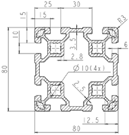 | A = 18.2 cm2 Ix = 132.1 cm4 Iy = 132.1 cm4 Wx = 33.0 cm3 Wy = 33.0 cm3 m = 4.9 kg | ISO: AlMgSi 0.5 F25 U.S. equivalent: AW-6063-T66 |
| Bosch profile 80 × 40 L mm |  | A = 9.9 cm2 Ix = 63.4 cm4 Iy = 17.3 cm4 Wx = 15.9 cm3 Wy = 8.7 cm3 m = 4.9 kg | ISO: AlMgSi 0.5 F25 U.S. equivalent: AW-6063-T66 |
| Connecting plate 25 × 100 mm |  | A = 25 cm2 Ix = 63.4 cm4 Iy = 17.3 cm4 | EN: S235JR (STN: 11 375) |
| Material Type | Young’s Modulus in Tension E [GPa] | Poisson’s Ratio μ [-] | Yield Strength Re [MPa] | Ultimate Strength Rm [MPa] |
|---|---|---|---|---|
| AlMgSi 0.5 F25 | 70 | 0.34 | 200 | 250 |
| Used Profiles | Cross-Section of the Profile with Dimensions | Material |
|---|---|---|
| I profile (HEB100) |  | EN: S235JR (STN: 11 375) |
| Jäkl profile (80 × 80 × 4) | 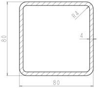 | EN: S235JR (STN: 11 375) |
| Top plate (25 × 100) | 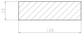 | EN: S235JR (STN: 11 375) |
| Material Type | Young’s Modulus in Tension E [GPa] | Poisson’s Ratio μ [–] | Yield Strength Re [MPa] | Ultimate Strength Rm [MPa] |
|---|---|---|---|---|
| S235JR | 200 | 0.3 | 240 | 360–510 |
| Fastening material, strength class 8.8 | 200 | 0.3 | 640 | 800 |
| Variable | Description | Variable Value |
|---|---|---|
| γ | Thread pitch angle | |
| Thread pitch value for the M12 screw | = 1.75 mm | |
| Φ′ | Friction angle considering the thread profile | |
| Coefficient of friction between the nut (or screw head) and the material | ||
| Mean thread diameter for the M12 screw | ||
| Friction radius | ||
| δ | Hole diameter for the screw for M12 | |
| Hexagonal dimension of the nut or screw head for the M12 screw |
| Construction Variant | Maximum Value of Equivalent Stress at the Given Location [MPa] | Yield Strength [MPa] | Safety Factor [-] |
|---|---|---|---|
| Welded | 13.5 | 240 | 17.8 |
| Assembled | 24.5 | 200 | 8.2 |
Disclaimer/Publisher’s Note: The statements, opinions and data contained in all publications are solely those of the individual author(s) and contributor(s) and not of MDPI and/or the editor(s). MDPI and/or the editor(s) disclaim responsibility for any injury to people or property resulting from any ideas, methods, instructions or products referred to in the content. |
© 2025 by the authors. Licensee MDPI, Basel, Switzerland. This article is an open access article distributed under the terms and conditions of the Creative Commons Attribution (CC BY) license (https://creativecommons.org/licenses/by/4.0/).
Share and Cite
Jakubovičová, L.; Vaško, M.; Synák, F. Evaluation of Load-Bearing Performance and Cost Efficiency in Steel-Welded and Modular Aluminum Rack Structures. Machines 2025, 13, 506. https://doi.org/10.3390/machines13060506
Jakubovičová L, Vaško M, Synák F. Evaluation of Load-Bearing Performance and Cost Efficiency in Steel-Welded and Modular Aluminum Rack Structures. Machines. 2025; 13(6):506. https://doi.org/10.3390/machines13060506
Chicago/Turabian StyleJakubovičová, Lenka, Milan Vaško, and František Synák. 2025. "Evaluation of Load-Bearing Performance and Cost Efficiency in Steel-Welded and Modular Aluminum Rack Structures" Machines 13, no. 6: 506. https://doi.org/10.3390/machines13060506
APA StyleJakubovičová, L., Vaško, M., & Synák, F. (2025). Evaluation of Load-Bearing Performance and Cost Efficiency in Steel-Welded and Modular Aluminum Rack Structures. Machines, 13(6), 506. https://doi.org/10.3390/machines13060506