
Study of the Influence of the Two-Drive-Axle Bogie Parameters on the Three-Axle Vehicle Handling

 , , , ,
  ,
,  and
and
Abstract
1. Introduction
- Develop a mathematical model of the movement of the bogie wheel along a curvilinear trajectory;
- Determine the kinematics of the steered wheels taking into account the bogie and vehicle wheelbases, kinematic and elastic parameters of the steering trapezoid, tire characteristics, and direction of turning;
- Conduct research and obtain an analytical dependence for calculating the minimum turning radius of a three-axle vehicle;
- Experimentally determine the reliability of the obtained analytical dependencies that characterize the movement of the bogie wheels along a curvilinear trajectory and determine the minimum turning radius.
2. Materials and Methods
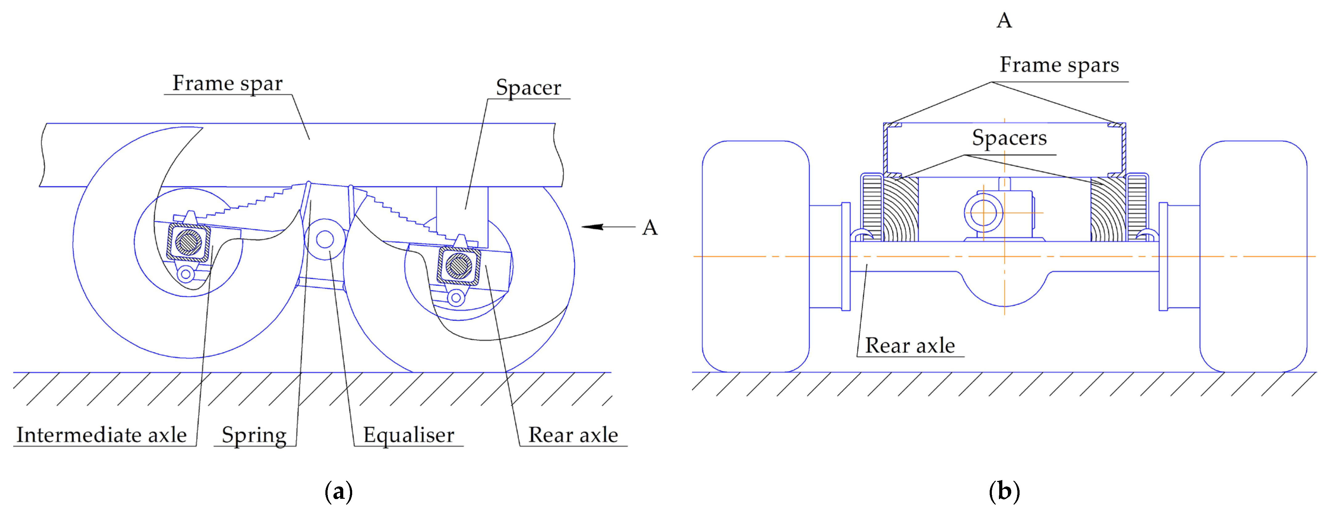
2.1. Mathematical Model of a Bogie Wheel
- The elastic bogie wheel is considered as a complex mechanism that includes a hard disk, an elastic tire body, and a tire contact patch [22];
- The support surface is a horizontal road with an asphalt concrete surface;
- The tire contact patch is reduced to an equal-sized rectangle [10];
- The movement of the bogie is considered at a low constant speed without taking into account inertial forces;
- The power cylinder of the hydraulic power-assisted steering system provides a stable maximum steering angle of the inside steered wheel while moving along a trajectory of minimum radius.
2.2. Study of Steering Wheel Angles
2.3. Minimum Turning Radius
- During the movement of a three-axle vehicle along a curved trajectory, a force perpendicular to the vehicle frame acts from the bogie on the steering axle, which we will decompose into lateral and longitudinal.
- The lateral force causes the steered wheels to move with a slip, increases the load on the outside steered wheel, and decreases it on the inside one.
- The longitudinal force on each steered wheel generates a twisting moment relative to the kingpin axis, the effect of which on the kinematics of the steered wheels depends on their direction of turning, stiffness, and kinematics of the steering trapezoid as a spatial four-link mechanism.
- When turning left, the moment Mtw applied to the outside (right) wheel relative to the kingpin axis will cause, due to the deformation of the steering trapezoid and the elasticity of the tire, a decrease in the steering angle of the outside wheel. At the same time, the steering angle of the inside steered wheel is limited by the stop, and the twisting moment deforms the tire in the direction of increasing its steering angle.
- When turning right, the inside (right) steered wheel is subjected to a force through the steering trapezoid from the outside (left) steered wheel, which provides its maximum steering angle, limited by the stop. At the same time, the twisting moment due to the elasticity of the tire increases the steering angle. The outside (left) steered wheel is subjected to a twisting moment, which due to the elasticity of the tire reduces the steering angle. However, to ensure that the inside wheel turns to a stop, the steering angle of the outside wheel will be increased by the power cylinder of the power assist.
3. Results
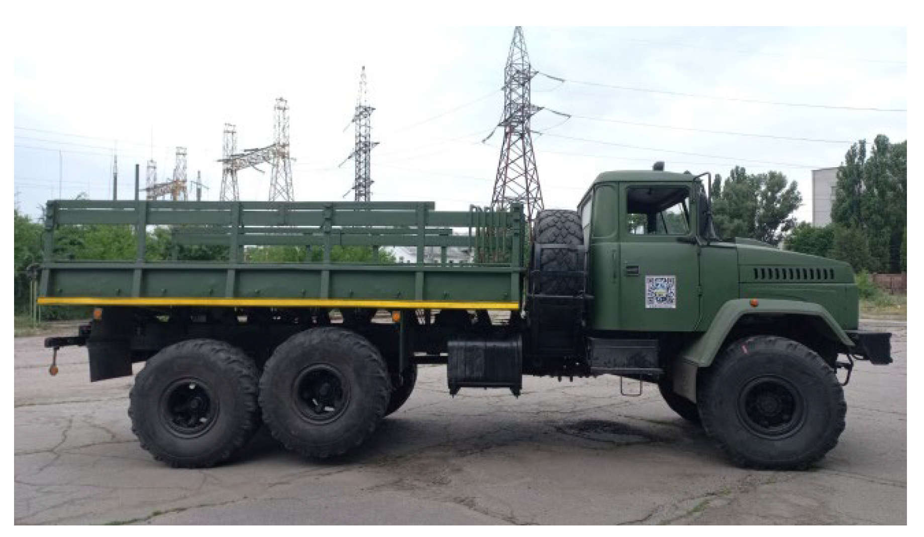
3.1. Initial Data of Research Objects
3.2. Analysis of Experimental Research Results
- The elastic bogie wheel while moving along a curvilinear trajectory simultaneously participates in two motions: curvilinear motion with the radius of the trajectory of the center of the bogie side and movement with a slip angle δ = 57.3lb/(2R) (deg);
- Increasing the load and the cornering stiffness of the steered wheel tires and reducing the load and the cornering stiffness of the bogie tires reduce the value of the minimum turning radius of the vehicle;
- The minimum turning radius of a three-axle vehicle reaches its maximum value when turning left when the vehicle is fully loaded. This must be taken into account when operating it;
- The coincidence of calculated and experimental data confirms the reliability of the mathematical model of the movement of the elastic bogie wheel along a curvilinear trajectory and the dependence for calculating the minimum turning radius, which allows determining the influence of the tire characteristics, the wheelbases of the bogie and the vehicle, the kinematic and elastic parameters of the steering trapezoid, the distribution of the load on the wheels, and the direction of turning.
4. Discussion
5. Conclusions
Author Contributions
Funding
Data Availability Statement
Conflicts of Interest
References
- Kostenko, A.V. The influence of the axles quantity of a multi-axle vehicle on tenability. Bull. SevNTU Ser. Mach.-Tool Eng. Transp. Collect. Sci. Work. 2013, 143, 49–52. (In Ukrainian) [Google Scholar]
- Trigell, A.S.; Rothhämel, M.; Pauwelussen, J.; Kural, K. Advanced vehicle dynamics of heavy trucks with the perspective of road safety. Veh. Syst. Dyn. 2017, 55, 1572–1617. [Google Scholar] [CrossRef]
- Qu, Q.; Zu, J.W. On Steering Control of Commercial Three-Axle Vehicle. J. Dyn. Sys. Meas. Control. 2008, 130, 021010. [Google Scholar] [CrossRef]
- Wang, S.; Zhang, J.; Li, H. Steering performance simulation of three-axle vehicle with multi-axle dynamic steering. In Proceedings of the 2008 IEEE Vehicle Power and Propulsion Conference, Harbin, China, 3–5 September 2008; IEEE: Piscataway, NJ, USA, 2008; pp. 1–5. [Google Scholar] [CrossRef]
- Kang, Y.-H.; Pang, D.-C.; Zeng, Y.-C. Optimal Dimensional Synthesis of Ackermann Steering Mechanisms for Three-Axle, Six-Wheeled Vehicles. Appl. Sci. 2025, 15, 800. [Google Scholar] [CrossRef]
- Song, Y.; Zhang, Z.; Zhou, K.; Zhou, J.; Gong, D.; Zhang, Y.; Li, X. Analytical study and optimisation of wheel–rail wear on curved track under traction/braking conditions. Veh. Syst. Dyn. 2025, 1–19. [Google Scholar] [CrossRef]
- Zeng, Y.; Chen, B.; Chi, Q.; Zhang, X. Wheel Wear Modeling and Re-Profiling Strategy Optimization Based on the Maintenance Data of a Three-Axle Bogie Locomotive. Transp. Res. Rec. 2024. [Google Scholar] [CrossRef]
- Pauwelussen, J. The Essentials of Vehicle Dynamics; Butterworth-Heinemann: Oxford, UK, 2014; 309p. [Google Scholar]
- Hu, X.; Huang, Y.; Ma, Y.; Zhao, J.; Li, W.; Mi, C.; Yang, C. Dynamic analysis of cross brace anti-warp stiffness performance for heavy haul freight wagon. Veh. Syst. Dyn. 2025, 1–23. [Google Scholar] [CrossRef]
- Soltus, A.P. Teorija Ekspluatacijnyh Vlastyvostej Avtomobilja (Theory of Operational Properties of the Vehicle); Aristej: Kyiv, Ukraine, 2010; 155p. (In Ukrainian) [Google Scholar]
- Ellis, J.R. Vehicle Handling Dynamics; Mechanical Engineering Publications: London, UK, 1994; 199p. [Google Scholar]
- Winkler, C.B.; Gillespie, T.D. On the Directional Response Characteristics of Heavy Trucks. Veh. Syst. Dyn. 1977, 6, 120–123. [Google Scholar] [CrossRef]
- Zhu, S.; Ni, Z.; Rahimi, A.; He, Y. On dynamic stability evaluation methods for long combination vehicles. Veh. Syst. Dyn. 2021, 60, 3999–4034. [Google Scholar] [CrossRef]
- Fancher, P.S.; Winkler, C.B. Directional performance issues in evaluation and design of articulated heavy vehicles. Veh. Syst. Dyn. Int. J. Veh. Mech. Mobil. 2007, 45, 607–647. [Google Scholar] [CrossRef]
- Williams, D.E. On the equivalent wheelbase of a three-axle vehicle. Veh. Syst. Dyn. 2011, 49, 1521–1532. [Google Scholar] [CrossRef]
- Williams, D.E. Generalized multi-axle vehicle handling. Veh. Syst. Dyn. 2012, 50, 149–166. [Google Scholar] [CrossRef]
- Williams, D.E. Handling Benefits of Steering a Third Axle. Proc. Inst. Mech. Eng. Part D J. Automob. Eng. 2010, 224, 1501–1511. [Google Scholar] [CrossRef]
- Zhang, Y.; Huang, Y.; Wang, H.; Khajepour, A. A comparative study of equivalent modeling for multi-axle vehicles. Veh. Syst. Dyn. 2017, 56, 443–460. [Google Scholar] [CrossRef]
- Oh, K.; Seo, J.; Kim, J.G.; Yi, K. MPC-based approach to optimized steering for minimum turning radius and efficient steering of multi-axle crane. Int. J. Control Autom. Syst. 2017, 15, 1799–1813. [Google Scholar] [CrossRef]
- Wong, J.Y. Theory of Ground Vehicles, 3rd ed.; JohnWiley & Sons, Inc.: New York, NY, USA, 2001; 528p. [Google Scholar]
- Pacejka, H. Tire and Vehicle Dynamics; Elsevier: Amsterdam, The Netherlands, 2005. [Google Scholar]
- Mateichyk, V.; Soltus, A.; Klimov, E.; Kostian, N.; Smieszek, M.; Kovbasenko, S. Regularities of Changes in the Motion Resistance of Wheeled Vehicles along a Curvilinear Trajectory. Machines 2023, 11, 570. [Google Scholar] [CrossRef]
- Gillespie, T. (Ed.) Fundamentals of Vehicle Dynamics; SAE International: Warrendale, PA, USA, 1992; 526p. [Google Scholar]
- Mateichyk, V.; Soltus, A.; Smieszek, M.; Klimov, E.; Kostian, N.; Tarandushka, L.; Marchuk, R. The Influence of Steering Axle Design Parameters and Operational Factors on Tire Steering Resistance Torque. Appl. Sci. 2024, 14, 10925. [Google Scholar] [CrossRef]

| Vehicle | Wheel Formula | Distance Between the Steering Axle and the Intermediate Axle, mm | Wheel-Base Ratio lb/L | Bogie Characteristics | |
|---|---|---|---|---|---|
| Wheel-Base lb, mm | Single/Dual Tires | ||||
| KrAZ–6322–02 (JSC “AutoKrAZ”, Kremenchuk, Ukraine) | 6 × 6 | 4600 | 0.2642 | 1400 | single |
| KrAZ–65055–040 (JSC “AutoKrAZ”, Kremenchuk, Ukraine) | 6 × 4 | 4080 | 0.2929 | 1400 | dual |
| MAZMAN–752559 (MAN Truck & Bus SE, Munich, Germany) | 6 × 4 | 3300 | 0.35 | 1400 | dual |
| MAZ–6501 (OJSC “MAZ”, Minsk, Belarus) | 6 × 4 | 3875 | 0.306 | 1400 | dual |
| JAC N350 (JAC Motors, Hefei, China) | 6 × 4 | 4100 | 0.2827 | 1350 | dual |
| RENAULT KERAX chassis (Renault Trucks, Bourg-en-Bresse, France) | 6 × 4 | 3845 | 0.3024 | 1370 | dual |
| Foton Auman GTL BJ 3259 (Foton Motor, Beijing, China) | 6 × 4 | 3950 | 0.2919 | 1350 | dual |
| MAN–TGS 26.400 6X2 4 BL Rechtslenker (MAN Truck & Bus SE, Munich, Germany) | 6 × 4 | 4200 | 0.2857 | 1400 | dual |
| KAMAZ–5350 (PJSC “KAMAZ”, Naberezhnye Chelny, Russia) | 6 × 6 | 3690 | 0.3034 | 1320 | single |
| KAMAZ 6520 (PJSC “KAMAZ”, Naberezhnye Chelny, Russia) | 6 × 4 | 3600 | 0.3333 | 1440 | dual |
| KAMAZ 65115 (PJSC “KAMAZ”, Naberezhnye Chelny, Russia) | 6 × 4 | 3190 | 0.3428 | 1320 | dual |
| Ford Trucks 2533 DC chassis (Ford Otosan, Inonu, Turkey) | 6 × 4 | 4250 | 0.2688 | 1320 | dual |
| Ford Trucks 3333 DC chassis (Ford Otosan, Inonu, Turkey) | 6 × 4 | 4500 | 0.2609 | 1350 | dual |
| Chassis Iveco T-WAY AD380T43H (Iveco S.p.A., Piacenza, Italy) | 6 × 4 | 4209 | 0.2817 | 1380 | single |
| Chassis Iveco T-WAY AD380T48H (Iveco S.p.A., Piacenza, Italy) | 6 × 4 | 4479 | 0.267 | 1380 | dual |
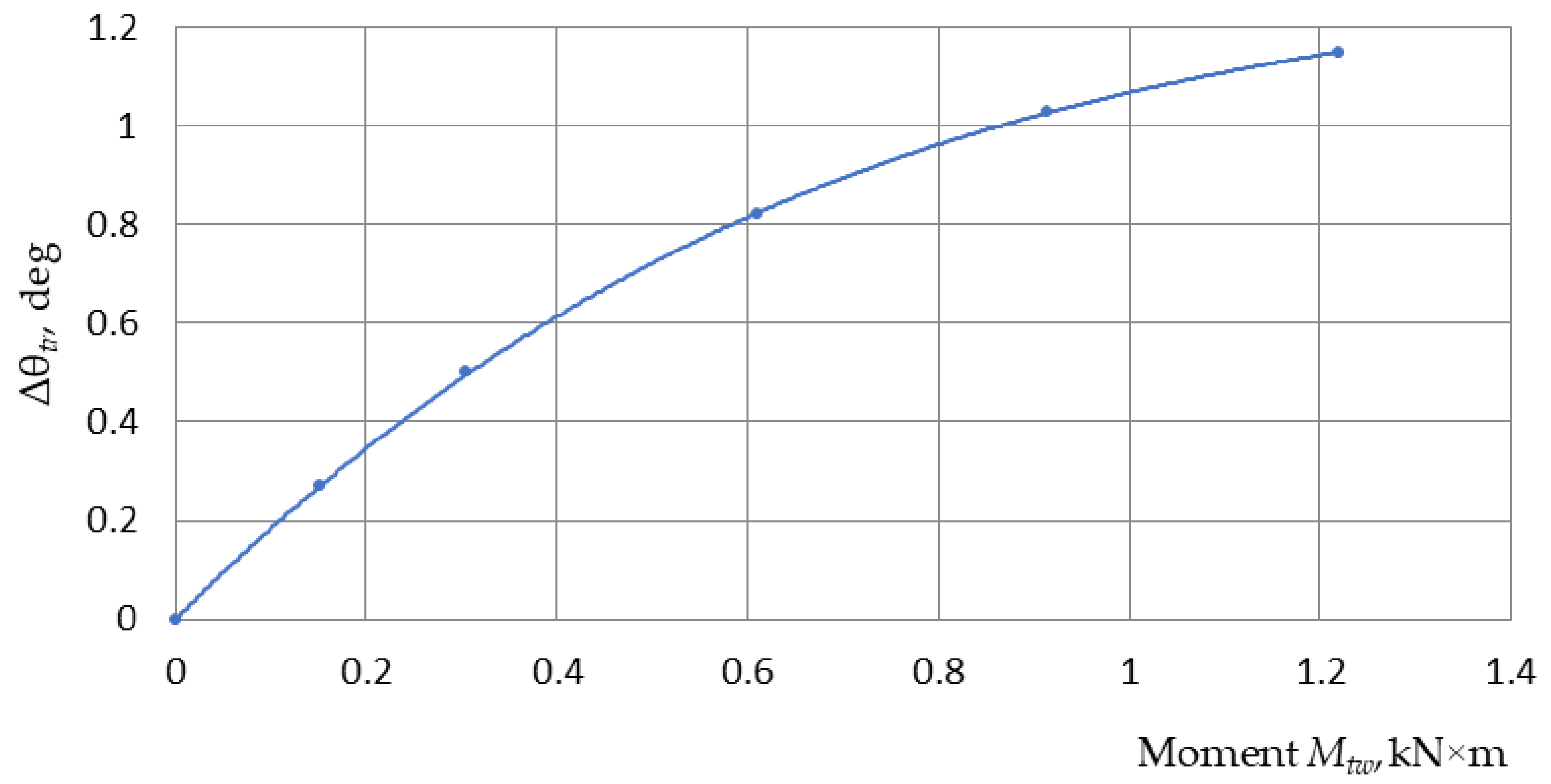
| Mtw, N×m | Δθtr, deg | Mtw, N×m | Δθtr, deg |
|---|---|---|---|
| 0 | 0 | 610 | 0.82 |
| 152.5 | 0.27 | 915 | 1.03 |
| 305 | 0.5 | 1220 | 1.15 |
| Truck Characteristics | Truck State | ||
|---|---|---|---|
| Two-Axle Without Load | Three-Axle Without Load | Three-Axle With Load | |
| Truck weight, kg | 12,220 | 12,220 | 23,870 |
| Load on the steering axle, N | 62,800 | 62,800 | 68,500 |
| Load on the bogie (rear axle), N | 59,400 | 59,400 | 170,200 |
| Truck wheelbase, m | 6.0 | 5.3 | 5.3 |
| Bogie wheelbase, m | – | 1.4 | 1.4 |
| Wheel track: | |||
| bogie (rear axle), m | 2.16 | 2.16 | 2.16 |
| steering axle, m | 2.16 | 2.16 | 2.16 |
| Maximum steering angles: | |||
| outside wheel θomax, deg | 26.6 | 26.6 | 26.6 |
| inside wheel θimax, deg | 32.2 | 32.2 | 32.2 |
| Tires: | |||
| model | Dneproshina 21.5/75R21 model ID-370 (Dneproshina Ltd., Dnipro, Ukraine) | ||
| inflation pressure, MPa | 0.545 | ||
| bogie wheel tire | single | ||
| Dimensions of tire contact patches, m: | |||
| steered wheel | a = 0.217; b = 0.393 | a = 0.217; b = 0.393 | a = 0.232; b = 0.405 |
| non-steered wheel | a = 0.212; b = 0.397 | a = 0.18; b = 0.335 | a = 0.25; b = 0.414 |
| Angular stiffness of tires Cθ, N·m/deg (14): | |||
| steered wheel | 345.4 | 345.4 | 376.8 |
| non-steered wheel | 326.7 | 163.4 | 468.0 |
| Cornering stiffness ks, N/deg (13): | |||
| steered wheel, | 3183 | 3183 | 3248.3 |
| non-steered wheel | 3082 | 1816 | 3744 |
| The distance from the support surface to the center of the frame h, m | 0.86 | 0.86 | 0.86 |
| Truck Characteristics | Truck State | ||
|---|---|---|---|
| Two-Axle Without a Load | Three-Axle Without a Load | Three-Axle With Load | |
| Truck weight, kg | 13,780 | 13,780 | 25,800 |
| Load on the steering axle, N | 59,400 | 59,400 | 59,600 |
| Load on the bogie (rear axle), N | 78,400 | 78,400 | 198,400 |
| Truck wheelbase, m | 6.4 | 5.7 | 5.7 |
| Bogie wheelbase, m | – | 1.4 | 1.4 |
| Wheel track: | |||
| bogie (rear axle), m | 1838 | 1838 | 1838 |
| steering axle, m | 2070 | 2070 | 2070 |
| Maximum steering angles: | |||
| outside wheel θomax, deg | 26.6 | 26.6 | 26.6 |
| inside wheel θimax, deg | 32.2 | 32.2 | 32.2 |
| Tires: | |||
| model | KAMA-201 12.00R20 (KAMA TYRES Ltd., Nizhnekamsk, Russia) | ||
| inflation pressure, MPa | 0.58 MPa | ||
| bogie wheel wheel | dual | ||
| Dimensions of tire contact patches, m: | |||
| steered wheel, | a = 0.264; b = 0.232 | a = 0.264; b = 0.232 | a = 0.265, b = 0.233 |
| non-steered dual wheel | a = 0.219; b = 0.541 | a = 0.153; b = 0.536 | a = 0.246; b = 0.546 |
| Angular stiffness of tires Cθ, N·m/deg (14): | |||
| steered wheel | 297 | 297 | 298 |
| non-steered dual wheel | 392 | 196 | 496 |
| Cornering stiffness ks, N/deg (13): | |||
| steered wheel; | 2249 | 2249 | 2250 |
| non-steered dual wheel. | 3580 | 2562 | 4032.5 |
| Distance from the support surface to the center of the frame h, m | 0.85 | 0.85 | 0.85 |
| Experimental and Calculated Data | Truck State | |||
|---|---|---|---|---|
| Two-Axle Without Load | Three-Axle Without Load L = 5.3 m | Three-Axle With Load L = 5.3 m | ||
| L = 6.0 m | L = 5.3 m | |||
| Minimum turning radius (experiment) Rmin, m | 13.4 | 11.84 | 12.5 | 13.15 |
| Turning radii of the bogie sides, m: | ||||
| inner side R | 9.82 | 8.427 | 9.16 | 9.96 |
| outer side R + Kb | 11.98 | 10.587 | 11.32 | 12.03 |
| Bogie turning resistance moment M, N·m (20): | – | – | 20,136 | 38,579 |
| Force on the steering axle Pb, N (21) | 3799.2 | 7279 | ||
| Calculated values of steering angles θ = f(Rmin), deg: | ||||
| outside wheel θo | 26.6 | 26.58 | 25.09 | 23.76 |
| inside wheel θi | 31.4 | 32.16 | 30.05 | 28.21 |
| average value θ | 29.0 | 29.37 | 27.57 | 25.98 |
| Lateral force on steered wheels Ps, N (26) | – | – | 3368 | 6440 |
| Slip angle of steered wheels δs, deg (30) | – | – | 0.529 | 1.007 |
| Load on the steered wheel, N: | ||||
| outside (28) | 31,400 | 31,400 | 32,907 | 36,846 |
| inside (29) | 31,400 | 31,400 | 29,895 | 31,654 |
| Longitudinal force on steered wheels Pl, N (27) | – | – | 1759 | 3188.6 |
| Twisting moment on the steered wheel Mtw, N·m (31) | – | – | 195.4 | 351.5 |
| Tire twisting angle Δθt, deg (32) | – | – | 0.56 | 0.933 |
| Reduction in the steering angle of the outside wheel due to the deformation of the steering trapezoid Δθtr, deg | – | – | 0.3 | 0.53 |
| The total decrease in the steering angle of the outside wheel Σθ = δs+ Δθt + Δθtr, deg | – | – | 1.389 | 2.47 |
| Steering angle of the outside wheel θo= θomax − Σθ, deg | 26.6 | 26.58 | 25.183 | 24.1 |
| Slip angle of the bogie wheels δb, deg (36) | – | – | 0.52 | 0.48 |
| Minimum turning radius Rmin, m (41) | 13.4 | 11.84 | 12.67 | 13.02 |
| Relative error, % | 0 | 0 | 1.36 | 0.98 |
| Truck State | Truck Weight, kg | Direction of Turning | Minimum Turning Radius Rmin, m |
|---|---|---|---|
| Three-axle without load | 12,220 | Left | 12.5 |
| Right | 11.95 | ||
| Three-axle with load | 23,870 | Left | 13.15 |
| Right | 12.35 |
| Experimental and Calculated Data | Truck State | |||
|---|---|---|---|---|
| Two-Axle Without Load | Three-Axle Without Load L = 5.7 m | Three-Axle With Load L = 5.7 m | ||
| L = 6.4 m | L = 5.7 m | |||
| Minimum turning radius (experiment) Rmin, m | 14.3 | 12.74 | 13.7 | 14.35 |
| Turning radii of the bogie sides, m: | ||||
| inner side R | 10.834 | 9.556 | 10.16 | 11.22 |
| outer side R + Kb | 12.672 | 11.39 | 12.0 | 13.05 |
| Bogie turning resistance moment M, N·m (20) | – | – | 26,145 | 36,990 |
| Force on the steering axle Rb, N (21) | – | – | 4586 | 6489 |
| Calculated values of steering angles θ = f(Rmin), deg: | ||||
| outside θo | 26.6 | 26.58 | 25.5 | 23.4 |
| inside θi | 30.9 | 30.5 | 28.6 | 26.7 |
| average value θ | 28.7 | 28.54 | 26.7 | 25.05 |
| Lateral force on steered wheels Ps, N (26) | – | – | 4097 | 5878 |
| Slip angle of steered wheels δs, deg (30) | – | – | 0.91 | 1.306 |
| Load on the steered wheel, N: | ||||
| outside (28) | 29,700 | 29,700 | 31,402 | 32,142 |
| inside (29) | 29,700 | 29,700 | 27,998 | 27,260 |
| Longitudinal force on steered wheels Pl, N (27) | – | – | 2060 | 2747 |
| Twisting moment on the steered wheel Mtw, N·m (31) | – | – | 227 | 302.85 |
| Tire twisting angle Δθt, deg (32) | – | – | 0.764 | 1.02 |
| Reduction in the steering angle of the outside wheel due to the deformation of the steering trapezoid Δθtr, deg | 0.27 | 0.5 | ||
| The total decrease in the steering angle of the outside wheel Σθ = δs+ Δθt + Δθtr, deg | – | – | 1.94 | 2.826 |
| Steering angle of the outside wheel θo= θomax − Σθ, deg | 26.6 | 26.58 | 24.63 | 23.754 |
| Slip angle of the bogie wheels δb, deg (36) | – | – | 0.4475 | 0.4023 |
| Minimum turning radius Rmin, m (41) | 14.3 | 12.74 | 13.89 | 14.36 |
| Relative error, % | 0 | 0 | 1.37 | 0.07 |
| Truck State | Truck Weight, kg | Direction of Turning | Minimum Turning Radius Rmin, m |
|---|---|---|---|
| Three-axle without load | 13,780 | Left | 13.7 |
| Right | 12.65 | ||
| Three-axle with load | 25,780 | Left | 14.35 |
| Right | 12.95 |
Disclaimer/Publisher’s Note: The statements, opinions and data contained in all publications are solely those of the individual author(s) and contributor(s) and not of MDPI and/or the editor(s). MDPI and/or the editor(s) disclaim responsibility for any injury to people or property resulting from any ideas, methods, instructions or products referred to in the content. |
© 2025 by the authors. Licensee MDPI, Basel, Switzerland. This article is an open access article distributed under the terms and conditions of the Creative Commons Attribution (CC BY) license (https://creativecommons.org/licenses/by/4.0/).
Share and Cite
Mateichyk, V.; Soltus, A.; Klimov, E.; Smieszek, M.; Kostian, N.; Tarandushka, L.; Marchuk, N. Study of the Influence of the Two-Drive-Axle Bogie Parameters on the Three-Axle Vehicle Handling. Machines 2025, 13, 394. https://doi.org/10.3390/machines13050394
Mateichyk V, Soltus A, Klimov E, Smieszek M, Kostian N, Tarandushka L, Marchuk N. Study of the Influence of the Two-Drive-Axle Bogie Parameters on the Three-Axle Vehicle Handling. Machines. 2025; 13(5):394. https://doi.org/10.3390/machines13050394
Chicago/Turabian StyleMateichyk, Vasyl, Anatolii Soltus, Eduard Klimov, Miroslaw Smieszek, Nataliia Kostian, Liudmyla Tarandushka, and Nazar Marchuk. 2025. "Study of the Influence of the Two-Drive-Axle Bogie Parameters on the Three-Axle Vehicle Handling" Machines 13, no. 5: 394. https://doi.org/10.3390/machines13050394
APA StyleMateichyk, V., Soltus, A., Klimov, E., Smieszek, M., Kostian, N., Tarandushka, L., & Marchuk, N. (2025). Study of the Influence of the Two-Drive-Axle Bogie Parameters on the Three-Axle Vehicle Handling. Machines, 13(5), 394. https://doi.org/10.3390/machines13050394