Article

Finite Element Analysis of Post-Buckling Failure in Stiffened Panels: A Comparative Approach

by
Jakiya Sultana
and
Gyula Varga
*
Faculty of Mechanical Engineering and Informatics, University of Miskolc, H-3515 Miskolc, Hungary
*
Author to whom correspondence should be addressed.
Machines 2025, 13(5), 373; https://doi.org/10.3390/machines13050373
Submission received: 19 March 2025 / Revised: 17 April 2025 / Accepted: 28 April 2025 / Published: 29 April 2025

Abstract

:
Stiffened panels are extensively used in aerospace applications, particularly in wing and fuselage sections, due to their favorable strength-to-weight ratio under in-plane loading conditions. This research employs the commercial finite element software Ansys-19 to analysis the critical buckling and ultimate collapse load of an aluminum stiffened panel having a dimension of 1244 mm (Length) × 957 mm (width) × 3.5 mm (thickness), with three stiffener blades located 280 mm away from each other. Both the critical buckling load and post-buckling ultimate failure load of the panel are validated against the experimental data found in the available literature, where the edges towards the length are clamped and simply supported, and the other two edges are free. For nonlinear buckling analysis, a plasticity power law is adopted with a small geometric imperfection of 0.4% at the middle of the panel. After the numerical validation, the investigation is further carried out considering four different lateral pressures, specifically 0.013 MPa, 0.065 MPa, 0.085 MPa, and 0.13 MPa, along with the compressive loading boundary conditions. It was found that even though the pressure application of 0.013 MPa did not significantly impact the critical buckling load of the panel, the ultimate collapse load was reduced by 18.5%. In general, the ultimate collapse load of the panel was severely affected by the presence of lateral pressure while edge compressing. Three opening shapes—namely, square, circular, and rectangular/hemispherical—were also investigated to understand the behavior of the panel with openings. It was found that the openings significantly affected the critical buckling load and ultimate collapse load of the stiffened panel, with the lateral pressure also contributing to this effect. Finally, in critical areas with higher lateral pressure load, a titanium panel can be a good alternative to the aluminum panel since it can provide almost twice to thrice better buckling stability and ultimate collapse load to the panels with a weight nearly 1.6 times higher than aluminum. These findings highlight the significance of precision manufacturing, particularly in improving and optimizing the structural efficiency of stiffened panels in aerospace industries.

1. Introduction

Stiffened panels are extensively used in aerospace structures because of their excellent strength capability and lightweight design [1]. The structural performance of these panels is mostly linked to the precision of their manufacturing processes, along with other considerations such as material properties and design [2]. Manufacturing-induced imperfections and residual stresses may lead to deviations from theoretical predictions, which result in unpredictable failures like sudden collapse, buckling, and so on [3,4]. Precision manufacturing processes may help to improve the accuracy of structures, reduce residual stresses, and minimize fabrication-induced imperfections, resulting in improve overall reliability, stability, and performance [5,6,7]. In addition, these geometric imperfections, material properties, and boundary conditions can all be significantly influenced by the precision of the manufacturing process [8,9].
These stiffened panels are mostly subjected to in-plane shear loading, which can lead to instability issues in the overall structure. Such in-plane loads may also cause structural failure—in particular, buckling, which often occurs when the material reaches its yield strength [10]. Therefore, the critical buckling results of the panels are the first priority to be taken into consideration before declaring a structure is safe. Due to their importance, stability problems of plates and panels are vastly investigated, and in most occurrences, these panels can be affected by in-plane loading conditions. However, on some occasions, the stiffened panel may be subject to lateral pressure loading conditions in combination with uniaxial compressive loading.
Numerous studies have been conducted to investigate the failure of various structures (such as plates and panels) and material failures, including critical buckling, post-buckling behavior, and ultimate collapse loads from both material and structural perspectives. However, most of them have discussed stability problems considering in-plane forces, for instance, under axial compression [11], shear loading [12], or a combination of both [13]. Both the governing differential equation and energy methods were solved to achieve the closed-form equations of the critical buckling load and deflection of a simply supported rectangular plate considering uniaxial compressive loading and lateral pressure. The expression was simplified, ignoring the higher-order strain terms, and it was suggested that the lateral pressure load would not significantly impact the buckling load when deformation was small [14]. However, in cases of increased pressure load, when the deformation is large, the prescribed equation for the rectangular plate would not be valid [15]. Later on, Yosiki et al. solved the governing equations adopting Galerkin’s theory and found that the load and deflection curve of the buckled waveform is highly influenced when it is experienced to a simply supported rectangular plate due to edge compression and also lateral hydraulic pressure [16]. Brown et al. found a similar conclusion, solving the plates’ stability problem under combined loading conditions [17].
A simplified approach to estimate the buckling load of isotropic plates with cutout area ratio and plate slenderness is proposed by Shanmugam et al. [18]. The results were found to be within an acceptable range, with an error percentage of 10%. Two different modeling approaches based on the finite strip method are constructed to calculate the critical buckling load and the free vibration of isotropic and layered composite plates with cutouts [19]. However, the formulation is only limited to predicting the stability of rectangular-shaped cutouts. It is generally found that the buckling load of a plate is reduced with increased opening area [20]. A comprehensive study adopting numerical methods on different opening shapes revealed that the central elliptical cutout, which is placed vertically, performs better among the investigated opening shapes [21]. In recent times, researchers adopted finite element methods for investigating plates with openings under edge compression, which have mainly been validated through experimentation [22,23,24,25].
In many cases, cutouts are inevitable and require stiffening around them. Some proposals on cutout stiffening with various stiffener shapes can be found in the literature [26,27]. For example, the critical buckling load of a composite C-section flange can be increased by 20.9% with a reinforcing L-shape stiffener [28]. Another study recommends that longitudinal and planer-type stiffeners can increase the buckling load capacity of panels by 2.8 and 1.9 times, in contrast to the panel without the stiffener [29]. A recent study showed that planar reinforcement enhances the buckling stability of simply supported plates with central circular holes considering various loading conditions [30]. Similarly, a previous study also improved the structural performance of stiffeners through numerical analysis and experimental testing [31].
In summary, an experimental testing system may be sufficient enough to analysis the buckling behavior of plates under combined loading conditions; however, for a stiffened panel, it is extremely troublesome to test since stringers may interrupt the uniform load distribution system. Moreover, stiffened panels under lateral loading conditions and edge compression have not been fully investigated. In addition, it is evident that an analytical solution is not readily available, with cutouts rarely achievable for plates, which, in extension to stiffened panels, are yet to be developed. Therefore, finite element methods are helpful in investigating such problems that correlate with experimentation. The current research work analyzes the buckling and post-buckling behavior of stiffened panels, adopting the well-known finite element method Ansys, which is further extended with different openings to fully understand their behavior under combined loading cases.

2. Finite Element Modeling

2.1. Geometry of the Stiffened Panel

For this numerical investigation, a stiffened panel is designed with a length of 1244 mm and a width of 957 mm. The plate thickness is kept constant at 3.5 mm, while the stiffener thickness is selected as 5.5 mm, and the gap between the stiffeners is set at 280 mm. The panel contains four stiffeners, each with a height of 40 mm. A complete three-dimensional geometry of the stiffened panel is shown in Figure 1a. The geometric model of the stiffened panel is created using Ansys Design Modeler. Details of the cutout and dimensions are presented in Figure 1b–d.

2.2. Material Modeling and Mesh Generation

To investigate the ultimate collapse load correctly, it is important to model the material beyond its elastic limit. Therefore, a plasticity model of the material is utilized with yield stress and ultimate stress values for both tension and compression. For the current research, a popular plasticity model named the nonlinear isotropic hardening power law is adopted for both the aluminum 2024 alloy and titanium alloy Ti-6Al-4V (Table 1). The material properties were obtained from the ANSYS material library.
The quadratic shell elements are adopted to mesh the stiffened panels, which are ideal for the numerical solutions of thin-walled structures. For the panel without a cutout, the element size is generated as 10 mm, which is the convergence point for the current solution. The total number of elements for square, circular, and hemispherical cylindrical openings are 13,720, 16,621, and 18,115, respectively. Some meshed stiffener examples are presented in Figure 1c.

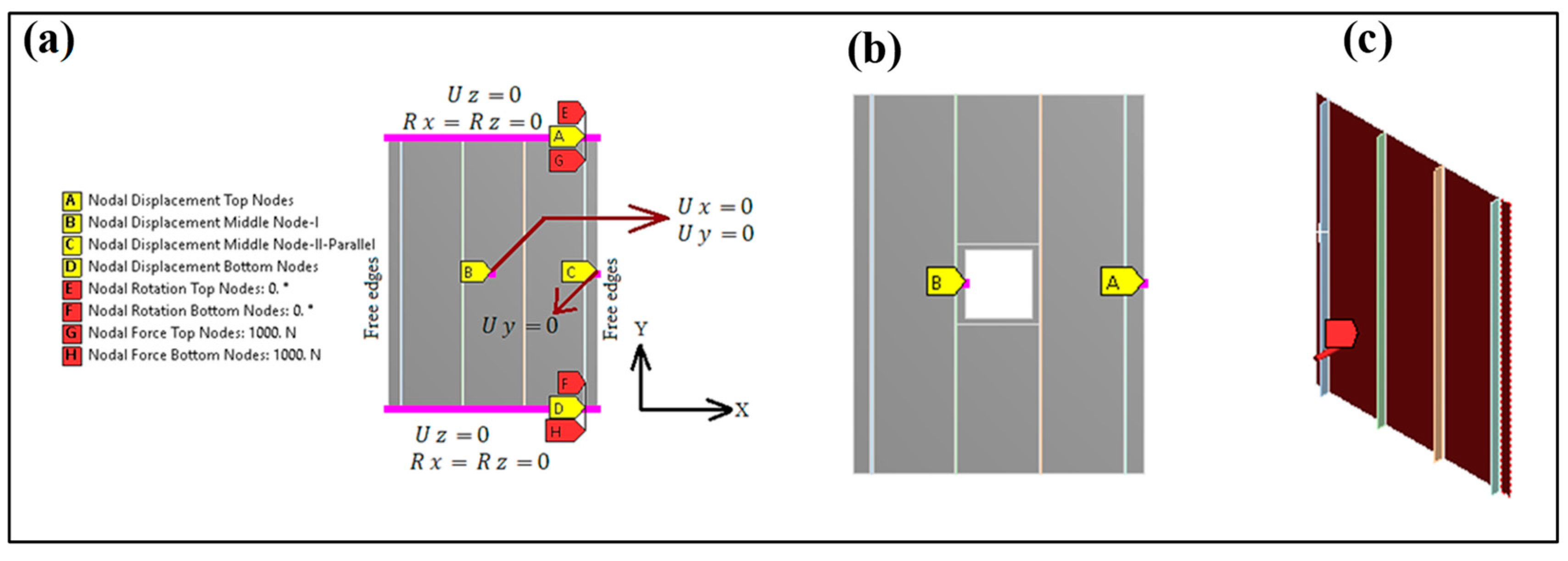
2.3. Applied Boundary and Loading Condition

The applied boundary and loading condition is similar to the experiments found in the literature [31]. To analysis the impact of the uniform lateral pressure on the buckling behavior of the stiffened panel, the following pressure loads are adopted according to the literature [32], where P0 = 0 MPa, P1 = 0.013 MPa, P2 = 0.065 MPa and P4 = 0.13 MPa, as shown in Figure 2a. The boundary conditions are also depicted in Figure 2a, including the applied load directions, edges, and rotational fixations. A similar study also applied lateral pressure ranging from 0 MPa to 0.25 MPa on stiffened panels [33]. At first, the lateral pressure load is subjected to the plate for a certain period, and, after that, unit loading is applied to the edges to attain the critical buckling load. Pressure and displacement are applied gradually to the panel for the nonlinear solution. Then, the ultimate collapse load is found by analyzing the load vs. end shortening graph.

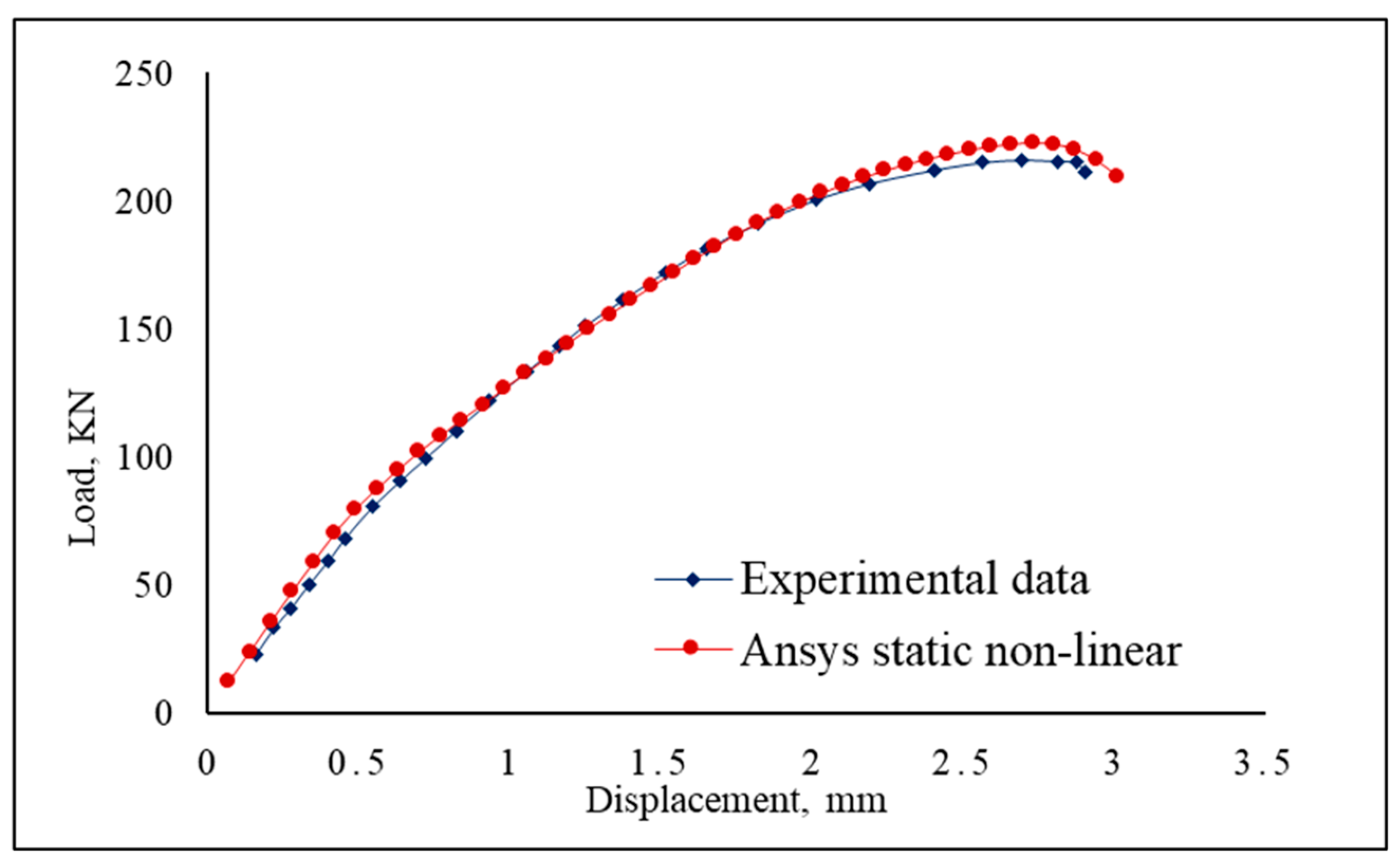
3. Numerical Validations with Experiments

In computer-aided engineering, validating numerical outcomes using experimental data is crucial. Confirming the correlation between experimental and numerical outcomes can ensure the confidence and consistency of subsequent numerical analysis. In this current study, the numerical data obtained from Ansys were compared to the experimental outcomes to validate this study, which were conducted considering particularly uniaxial loading conditions for a stiffener panel [31]. The numerical model was designed to replicate the geometry, boundary conditions, and loading scenarios of the stiffened panel, consistent with those presented in the literature [31].
The eigenmode and critical buckling load of the stiffener panel are compared with these studies [31]. From Figure 3, it can be observed that the author’s obtained eigenmode and the eigenmode from the literature both perfectly align with the previous study. However, the discrepancy between the critical buckling load of the stiffener panel with the author and that of the literature is 5.9%, which is acceptable, as shown in Table 2. A similar observation comparing the experimental and numerical results has been found in the literature, where the differences are 5–10% [34].
Furthermore, the estimated ultimate collapse load from the experimental load vs. displacement curve shows excellent agreement with the Ansys static nonlinear curve, as depicted in Figure 4. The computed ultimate collapse load deviates by only 2.7% from the experimental data, as shown in Table 3.
In these numerical investigations, the computational model considers the materials and geometry as nonlinear. In addition, similar properties are also considered in the current analysis. From the above comparison in between numerical and experimental outcomes, it can be postulated that Ansys could be a robust numerical tool sufficient to investigate this type of failure in the critical structure.

4. Results and Discussions

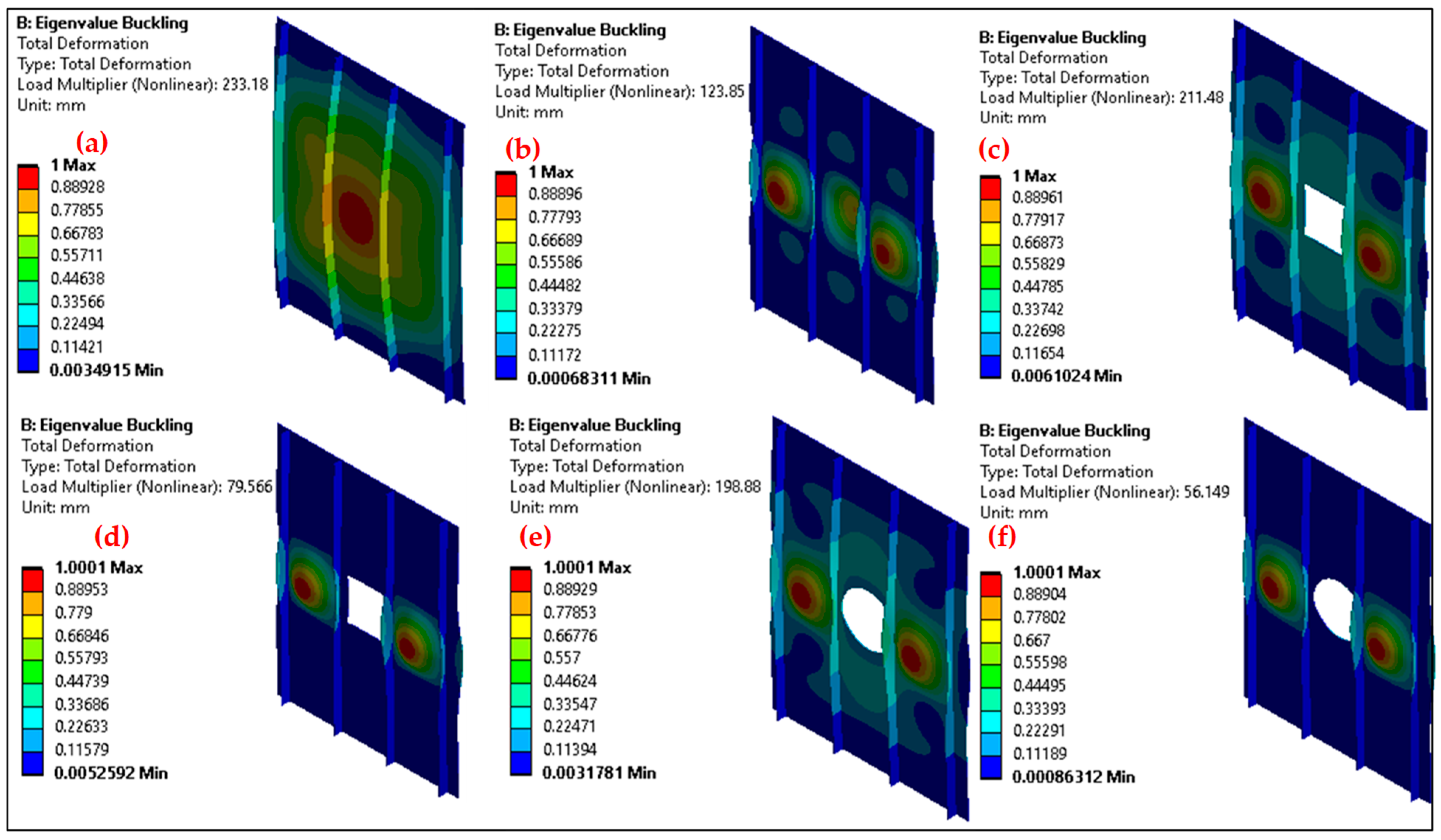
4.1. Al-Alloy 2024 Stiffened Panel

4.1.1. Stiffened Panel Without Opening

At first, results are discussed for the stiffened panel without any openings. It is worth noting that the critical buckling load decreases significantly for lateral pressure load application of 0.065 MPa and 0.13 MPa, as shown in Figure 5a,b.
The buckling load of the panel is decreased by 13.4% while applying the pressure of 0.065 MPa and 62% during the presence of 0.13 MPa pressure. Next, the ultimate collapse load is investigated for different pressure loading conditions. From the load vs. end shortening curve, Figure 5b, it is apparent that the application of pressure load would result in significantly lower ultimate collapse load values.
It is interesting to see that even though the pressure application of 0.013 MPa does not impact the critical buckling load of the stiffener panel, the collapse load is influenced severely, reduced by 22.24%, as shown in Figure 5b. The reduction in ultimate collapse load is 62.4% and 99.5% for pressure applications of 0.065 MPa and 0.13 MPa, respectively.

4.1.2. Stiffened Panel with Square Opening

Next, results are discussed for the stiffened panel with square openings. A similar trend is observed for the critical buckling load of the panel, while the buckling load does not have an effect when the pressure loading is 0.013 MPa, as shown in Figure 6a. Similarly, the presence of lateral pressure values of 0.065 MPa and 0.13 MPa would reduce the critical buckling load by 22.7% and 90.4%, respectively. Next, the ultimate collapse load is calculated for different pressure loading conditions. From the load vs. end shortening curve, in Figure 6b, it is evident that the presence of pressure load would result in significantly lower ultimate collapse load values, similar to the previous case study of stiffened panels without any opening. The reductions in ultimate collapse load are 18.5%, 61.7%, and 104.6% for pressure applications of 0.013 MPa, 0.065 MPa, and 0.13 MPa, respectively, as shown in Figure 6b.

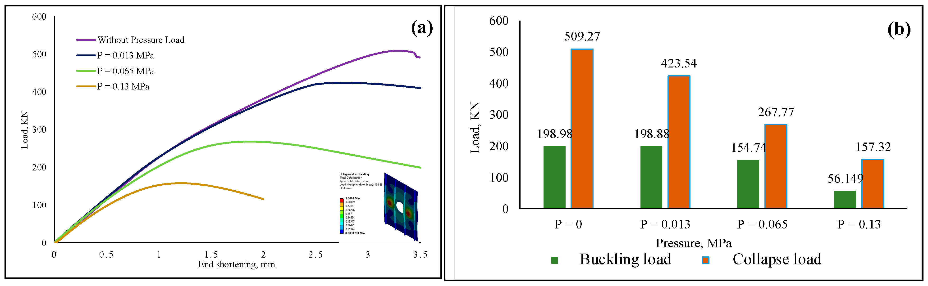
4.1.3. Stiffened Panel with Circular Opening

The critical buckling load is reduced while applying lateral pressure at 0.065 MPa and 0.13 MPa by 24.96% and 111.93%, respectively, as shown in Figure 7a,b. As the pressure load increases, a significant reduction in ultimate collapse load is inevitable, which is found to be evident for stiffened panels with circular openings, as well, from the load vs. the end-shortening curve, as shown in Figure 7a. The exact amount of reduction in ultimate collapse load is 18.31%, 62.16%, and 105.6% for the lateral pressure values of 0.013 MPa, 0.065 MPa, and 0.13 MPa, respectively, as shown in Figure 7b.

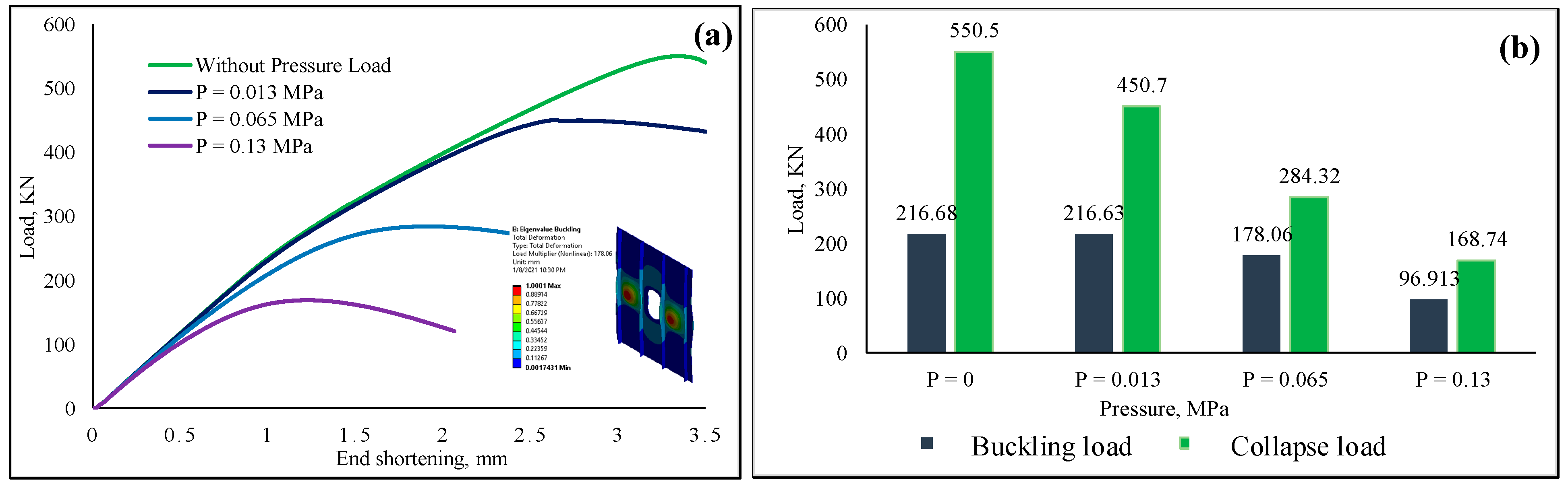
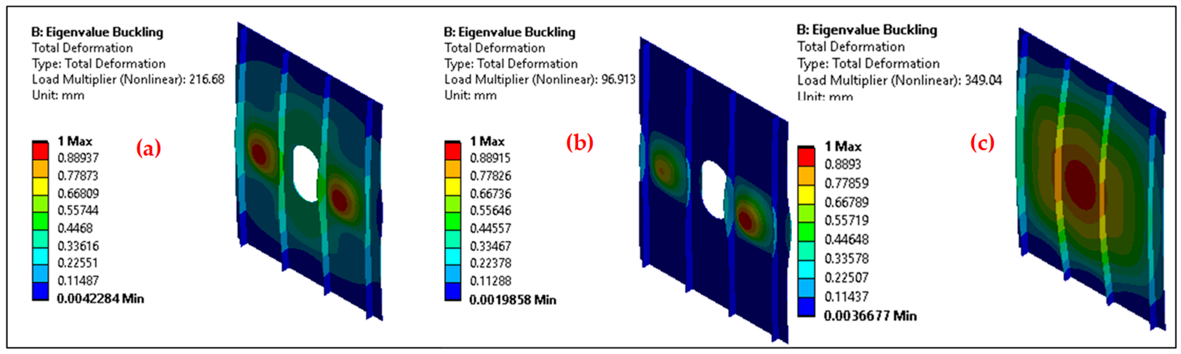
4.1.4. Stiffened Panel with Square/Hemispherical Opening

A slight exception is found for the pressure application of 0.13 MPa. For the case of 0.065 MPa and 0.13 MPa, the critical buckling load of the stiffened panel is reduced by 19.56% and 76.38%, respectively, as shown in Figure 8a,b. The ultimate collapse load is affected severely by lateral pressure load, which was observed previously by all other stiffened panels. A load vs. end shortening graph is plotted in Figure 8b to estimate the ultimate collapse load for corresponding lateral pressure application. The ultimate collapse load is reduced by 19.93%, 63.75%, and 106.15% for lateral pressure loads of 0.013 MPa, 0.065 MPa, and 0.13 MPa, respectively, as shown in Figure 8a,b.

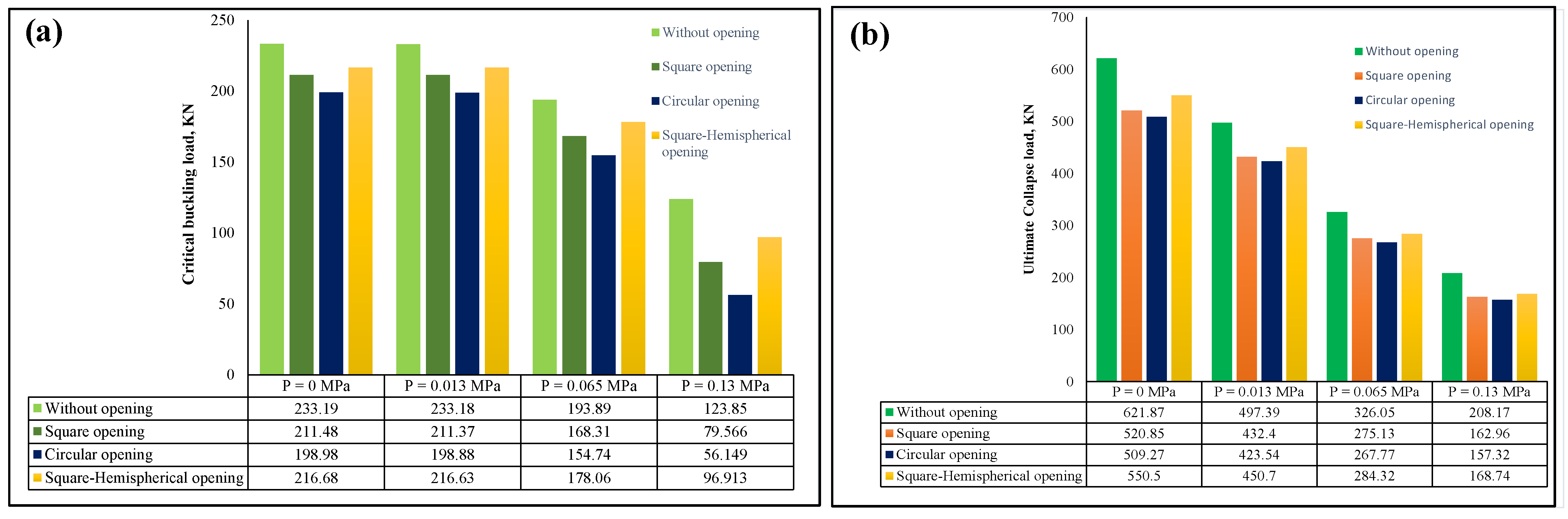
4.2. Comparison of Stiffened Panels Among Different Shapes

This section extensively studies a comparison of critical buckling load and ultimate collapse load due to the presence of different opening shapes in the stiffened panel. First, the buckling load of the designed panel is illustrated in Figure 9a.
When no lateral pressure is applied, the critical buckling load is reduced by 9.7% for the square opening shape; for the other two shapes investigated in this research, namely, circular and square/hemispherical shapes, approximately 15.8% and 7.33% of critical buckling load is lost, respectively. Since the presence of a lateral pressure load of 0.013 MPa does not affect the critical buckling load of the panels, the loss percentage is the same as in the previous study.
However, in terms of 0.065 MPa, approximately 14.1%, 22.45%, and 8.5% buckling load reduction is observed for the square, circular, and square/hemispherical shapes, respectively. A similar trend is observed for the lateral pressure of 0.13 MPa, where the critical load is decreased more severely than in the previous case, approximately 43.5%, 75.22%, and 24.4% for square, circular, and square/hemispherical shapes, respectively. A square/hemispherical opening provides a better critical buckling load to the stiffened panel among the three opening shapes. Even though the square shape offers almost identical critical buckling load to the square/hemispherical shape, the difference becomes evident when applying 0.13 MPa pressure, nearly 19.6%.
For the case of ultimate collapse load, the presence of opening shapes affects the ultimate collapse load significantly, as shown in Figure 9b. When no lateral pressure load is applied, the ultimate collapse load for the square shape is reduced by 17.7%, which is 19.9% and 12.17% for the circular and square/hemispherical shapes, respectively. After applying 0.013 MPa, the reduction percentage is 13.97%, 16%, and 9.84% for the square, circular, and square/hemispherical shapes, respectively. An almost similar trend is observed for the case of 0.065 MPa, when the reduction rate is 16.94%, 19.62%, and 13.67% for the square, circular, and square/hemispherical shapes, respectively. An identical trend is observed for the stiffened panels when applying the lateral pressure load of 0.13 MPa. Among the three opening shapes, similar to the critical buckling investigations, the square/hemispherical shape performed best among the investigated openings, while the circular-shaped panel exhibited the lowest collapse load.

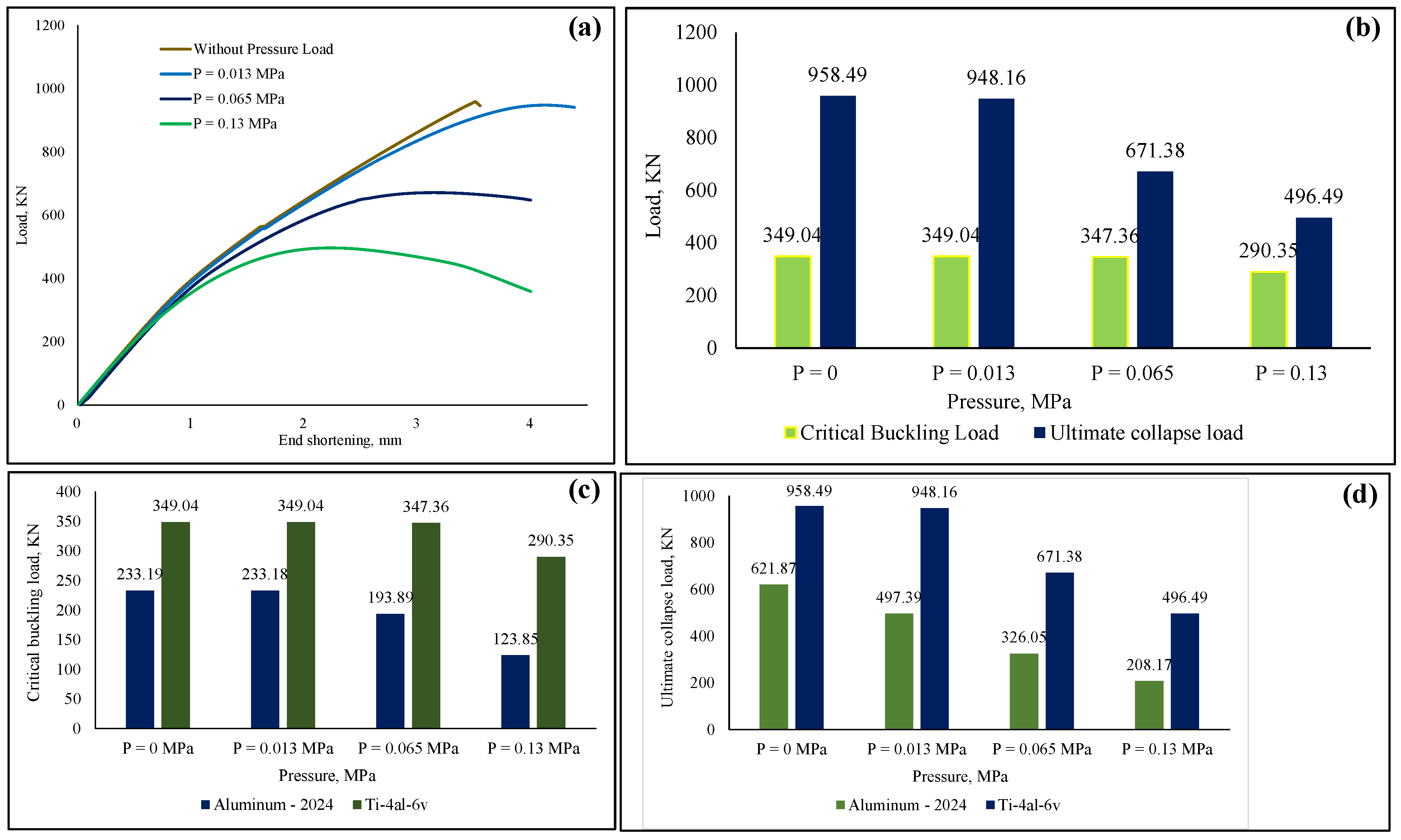
4.3. Titanium Alloy Ti-6Al-4V Stiffened Panel Comparisons

To further investigate the effect of lateral pressure load, a stiffened panel made of titanium alloy is studied and compared with a panel made of aluminum alloy. In terms of critical buckling load, some interesting observations are revealed. Despite the application of the lateral pressure load, the critical buckling load of the stiffened panel has not been affected significantly.
However, for applying the pressure load, 0.13 MPa, the buckling load is reduced by 17.9%, as shown in Figure 10a. Even though the critical buckling load is less affected by the pressure acting on the panel, the ultimate collapse load of the panel is severely affected by the presence of the lateral pressure load of 0.065 MPa and 0.13 MPa. The reduction in the ultimate collapse load is 35.231% and 62.5% for the application of 0.065 MPa and 0.13 MPa, respectively, as shown in Figure 10b.
Next, a comparative study between titanium and aluminum alloys is performed, as shown in Figure 10c,d. For analysis purposes, it is assumed that the panels made of titanium alloy are almost 1.5 times heavier than aluminum alloy. In cost of weight measuring 1.5 times, both the critical buckling load and ultimate collapse load are much higher for the titanium panels under any given pressure load. In the case of no pressure loading, the critical buckling and ultimate collapse load are almost 1.5 times higher than aluminum panels. However, as the value of the pressure load increases, both the differences in critical buckling load and ultimate collapse load increase significantly between the titanium alloy and aluminum alloy. For the pressure application of 0.13 MPa, the titanium panel’s critical buckling load and ultimate collapse load are 2.4 times higher than that of the aluminum panel.

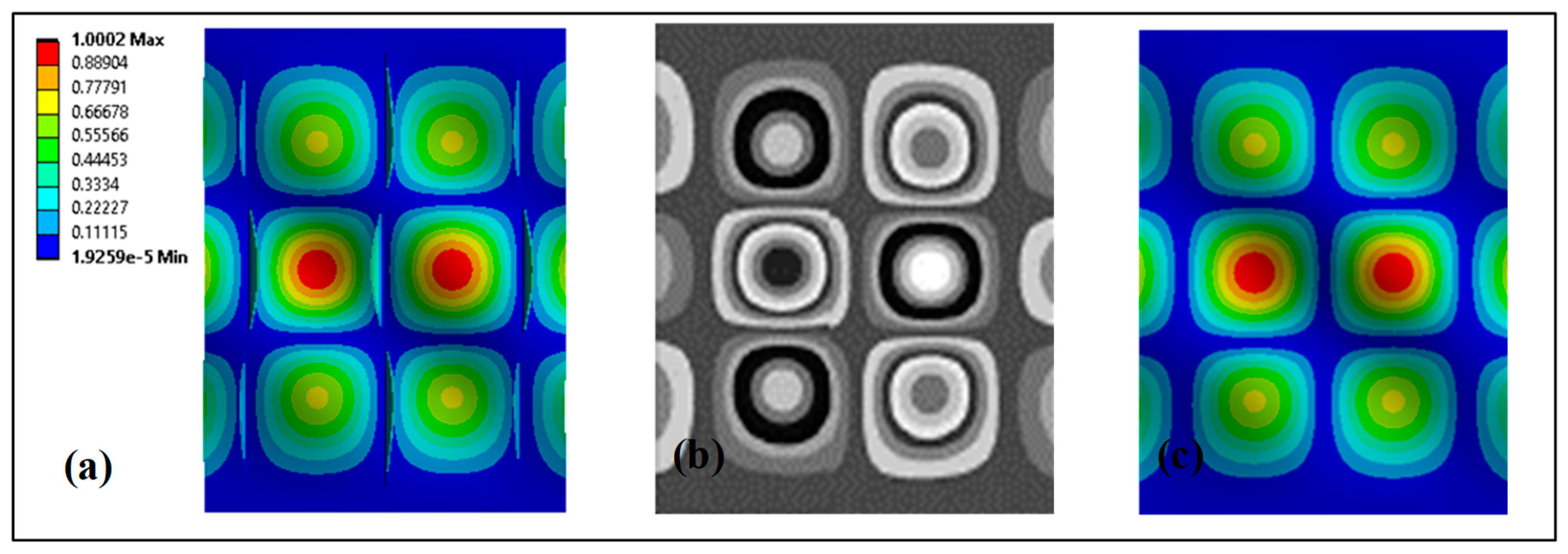
5. Eigenmode Shape Comparison

In this study, the eigenmode shapes of the stiffened panel are also compared for all considered cases. The eigenmodes are specifically presented for the highest and lowest critical buckling loads obtained under each condition—namely, without openings, square, circular, and square/hemispherical cutouts—in Figure 11 and Figure 12. As shown in Figure 11a,b, the eigenmode shape for the stiffened panel without openings differs significantly between the cases with 0 MPa and 0.13 MPa lateral pressure. This variation is likely due to the differences in lateral pressure, which also result in the highest and lowest critical buckling loads, with a difference of approximately 46.89%.
However, for the stiffened panel with a square cutout, the eigenmode shapes appear to be slightly similar in Figure 11c,d, despite the significant difference in the obtained critical buckling loads—211.37 kN at a lateral pressure of 0.013 MPa and 79.56 kN at a lateral pressure of 0.13 MPa.
In the stiffened panel with a circular cutout, the eigenmode shapes differ significantly from each other. This is likely due to the influence of the cutout shape and the applied lateral pressure. In Figure 11e,f, the eigenmode shapes are shown for the circular cutout under lateral pressures of 0 MPa and 0.13 MPa, respectively.
In the case of square/hemispherical openings, the eigenmode shapes vary due to the differences in applied lateral pressure. Figure 12a shows the eigenmode shape under a lateral pressure of 0.013 MPa, while Figure 12b corresponds to 0.13 MPa. Figure 12c presents the eigenmode shape specifically for the titanium alloy material. For the titanium alloy, the eigenmode shapes generally follow a similar pattern.

6. Future Research Scopes

Although this study thoroughly investigated various aspects of stiffened panels, such as lateral pressure, material considerations (with two different materials), different cutouts, and their dimensions, the authors acknowledge several areas for future research. These areas could focus on improving the geometry of stiffened panels and enhancing their performance from a precision manufacturing perspective. The potential research directions are outlined below.
  • This study did not consider mesh dependency, variations in boundary conditions, or geometric imperfections; a future parametric study can investigate these factors’ effects on the behavior of stiffened panels to improve geometric precision.
  • The investigation found that titanium alloy performs more efficiently than aluminum alloy. Although cost and weight reduction are primary concerns in the aerospace industry, future research could focus on comparing the weight of different cutout configurations in stiffened panels, along with conducting a life cycle cost analysis.
  • Geometric imperfections, such as residual stresses and geometric deviations, are crucial considerations for any type of structure. In this study, these factors were not investigated. However, future research could be conducted on stiffened panels, considering these unintentional faults, to improve the precision of manufacturing stiffened panels.
  • This research focused solely on lateral pressure ranging from 0 to 0.13 MPa. Other types of loads, such as dynamic loads, vibrations, and sudden shocks—commonly observed in the aerospace industry—were not considered in this study. Future investigations could be conducted to further understand the impact of these loads on real engineering applications from both material and structural perspectives.
  • Although the finite element method is sufficiently reliable for investigating stiffener failures, future studies could involve the application of lateral pressure through solid experimentations.

7. Conclusions

The main aim of this numerical investigation was to understand the effect of lateral pressure load on the critical buckling behavior and ultimate collapse load of the stiffened panels subjected to uniaxial compressive loading. The well-accepted commercial FE method Ansys was adopted to achieve numerical outcomes. Based on the simulation outcomes, the following findings can be highlighted.
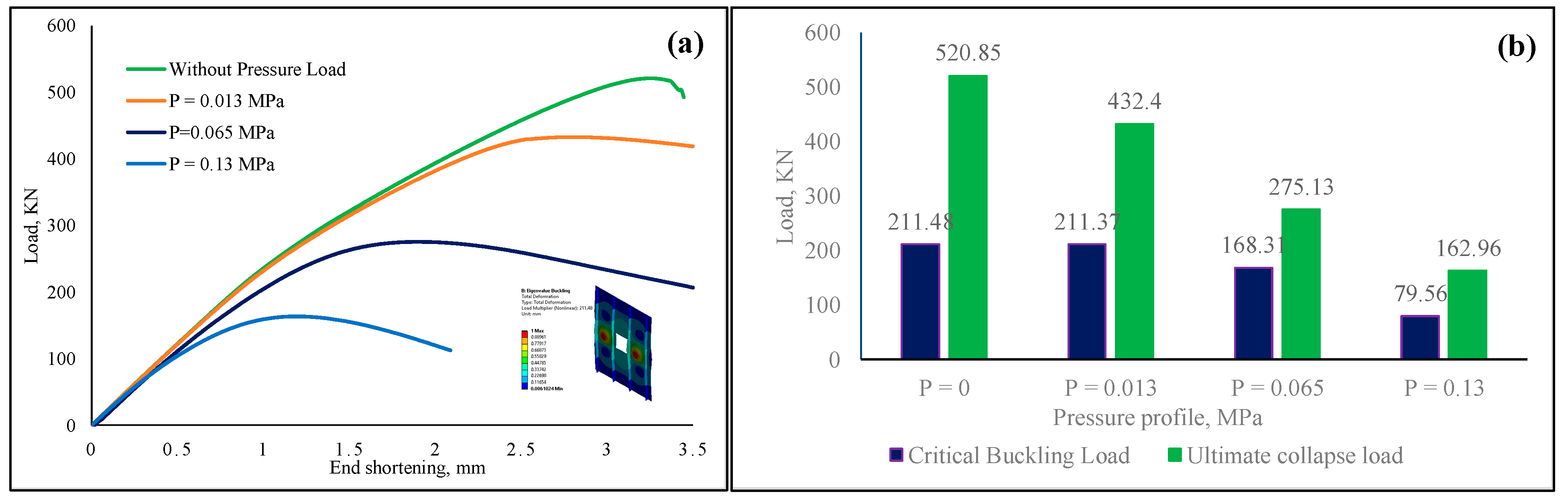
  • Among the investigated cases, a small amount of uniformly distributed lateral pressure load, to be precise, 0.013 MPa, did not remarkably impact the critical buckling load of the aluminum-based stiffened panels with or without opening shapes. However, the ultimate collapse load of the panel was affected by the lateral pressure load. In the case of titanium alloy, both the critical buckling and collapse load were not influenced by the prescribed pressure value.
  • For the pressure load of 0.065 MPa, both the critical buckling load and ultimate collapse load were significantly affected for aluminum stiffened panels with or without opening shapes. For titanium stiffened panels, even though the critical buckling load was not affected by the pressure, the ultimate collapse load was found to be reduced by 35%.
  • A significant percentage of buckling load and ultimate collapse load was found to be reduced by the application of 0.13 MPa pressure load for both aluminum and titanium panels. For the aluminum-based panels, the reduction in critical buckling load was not less than 60%, which was more severe for the ultimate collapse load, from 100% to 115%. For the case of the titanium panel, even though the critical buckling load was reduced by around 18.5%, the ultimate collapse load was almost reduced by 63%.
  • The presence of opening shapes always reduced the critical buckling load and ultimate collapse load of the stiffened panel subjected to uniaxial compressive loading. The loss was more evident when the panel was subjected to both uniaxial compressive loading and lateral pressure load.
  • Among the opening shapes investigated in this research, the square/hemispherical shape provided better buckling stability and ultimate collapse load to the stiffened panel. Although the square shape provided almost similar outcomes, for the pressure load of 0.13 MPa, the square/hemispherical shape exhibited better stability for the panel, around 20% higher than the square-shaped opening.
  • From the investigated results, it is apparent that the lateral pressure load significantly affected the panel’s critical buckling and collapse load. The presence of the pressure load cannot be ignored and should be considered a crucial factor during the calculation of a stiffened panel subjected to uniform pressure loading conditions.
  • From the mechanical properties of the titanium and aluminum alloys, it is evident that under any loading condition, titanium alloy would provide better strength than aluminum alloy with the cost of weight. Despite being lightweight, achieving the safety of a structure made from aluminum alloy is not always possible. In such conditions, titanium alloy can be utilized since it provides almost twice to thrice better buckling stability and ultimate collapse load to the panels.

Author Contributions

Conceptualization, J.S. and G.V.; methodology, J.S. and G.V.; software, J.S. and G.V.; validation, J.S.; formal analysis, J.S.; investigation, J.S. and G.V.; resources, J.S. and G.V.; data curation, J.S. and G.V.; writing—original draft preparation, J.S.; writing—review and editing, J.S. and G.V.; supervision, G.V.; project administration, J.S. and G.V.; funding acquisition. All authors have read and agreed to the published version of the manuscript.

Funding

This research received no external funding.

Data Availability Statement

All data have been shown in the paper.

Conflicts of Interest

The authors declare no conflicts of interest.

References

  1. Ren, R.; Ma, X.; Yue, H.; Yang, F.; Lu, Y. Stiffness Enhancement Methods for Thin-Walled Aircraft Structures: A Review. Thin-Walled Struct. 2024, 201, 111995. [Google Scholar] [CrossRef]
  2. Zhu, J.H.; Zhang, W.H.; Xia, L. Topology Optimization in Aircraft and Aerospace Structures Design. Arch. Comput. Methods Eng. 2016, 23, 595–622. [Google Scholar] [CrossRef]
  3. Pietropaoli, E.; Riccio, A. Finite Element Analysis of the Stability (Buckling and Post-Buckling) of Composite Laminated Structures: Well Established Procedures and Challenges. Appl. Compos. Mater. 2012, 19, 79–96. [Google Scholar] [CrossRef]
  4. Cruz, M.L.S.; Carrillo, J.; De Almeida, S.F.M. Effect of Thermal Residual Stresses on Buckling and Post-Buckling Properties of Laminated Composites Perimetrally Reinforced. Lat. Am. J. Solids Struct. 2016, 13, 435–455. [Google Scholar] [CrossRef]
  5. Godoy, L.A. Stresses and Pressures in Thin-Walled Structures with Damage and Imperfections. Thin-Walled Struct. 1998, 32, 181–206. [Google Scholar] [CrossRef]
  6. Yip, W.S.; To, S.; Zhou, H. Current Status, Challenges and Opportunities of Sustainable Ultra-Precision Manufacturing. J. Intell. Manuf. 2022, 33, 2193–2205. [Google Scholar] [CrossRef]
  7. Ellinas, B.C.P. Buckling design of Ring-Stiffened Cylinders 3. JWPCO 1985, 110, 413–431. [Google Scholar] [CrossRef]
  8. Dallago, M.; Winiarski, B.; Zanini, F.; Carmignato, S.; Benedetti, M. On the Effect of Geometrical Imperfections and Defects on the Fatigue Strength of Cellular Lattice Structures Additively Manufactured via Selective Laser Melting. Int. J. Fatigue 2019, 124, 348–360. [Google Scholar] [CrossRef]
  9. Cervi, C.; Virgin, L.N. An Experimental Parametric Study Assessing the Effect of a Certain Initial Geometric Imperfection on Cylinder Buckling. Aerosp. Sci. Technol. 2024, 152, 109355. [Google Scholar] [CrossRef]
  10. Kordas, P.D.; Lampeas, G.N.; Fotopoulos, K.T. Numerical Investigation of an Experimental Setup for Thermoplastic Fuselage Panel Testing in Combined Loading. Aerospace 2024, 11, 175. [Google Scholar] [CrossRef]
  11. Ghadami, A.; Jawdhari, A.; PourMoosavi, G. Buckling and Post-Buckling Behavior of Top Flange Coped I-Beams with Slender Web Panels. Thin-Walled Struct. 2024, 198, 111640. [Google Scholar] [CrossRef]
  12. Carrera, E.; Azzara, R.; Daneshkhah, E.; Pagani, A.; Wu, B. Buckling and Post-Buckling of Anisotropic Flat Panels Subjected to Axial and Shear in-Plane Loadings Accounting for Classical and Refined Structural and Nonlinear Theories. Int. J. Non. Linear. Mech. 2021, 133, 103716. [Google Scholar] [CrossRef]
  13. Ueda, Y.; Rashed, S.M.H.; Paik, J.K. Buckling and Ultimate Strength Interaction in Plates and Stiffened Panels under Combined Inplane Biaxial and Shearing Forces. Mar. Struct. 1995, 8, 1–36. [Google Scholar] [CrossRef]
  14. Lal, M.G. Stability Analysis and Design of Structures; Springer Science & Business Media: New York, NY, USA, 2013. [Google Scholar]
  15. Barkanov, E.; Ozoliņš, O.; Eglitis, E.; Almeida, F.; Bowering, M.C.; Watson, G. Optimal Design of Composite Lateral Wing Upper Covers. Part I: Linear Buckling Analysis. Aerosp. Sci. Technol. 2014, 38, 1–8. [Google Scholar] [CrossRef]
  16. Yosiki, M.; Yamamoto, Y.; Kondo, H. Buckling of Plates Subjected to Edge Thrusts and Lateral Pressure. J. Zosen Kiokai 1965, 118, 249–258. [Google Scholar] [CrossRef]
  17. Brown, J.C.; Harvey, J.M. Large Deflections of Rectangular Plates Subjected To Uniform Lateral Pressure and Compressive Edge Loading. J. Mech. Eng. Sci. 1969, 11, 305–317. [Google Scholar] [CrossRef]
  18. Shanmugam, N.E.; Thevendran, V.; Tan, Y.H. Design Formula for Axially Compressed Perforated Plates. Thin-Walled Struct. 1999, 34, 1–20. [Google Scholar] [CrossRef]
  19. Ovesy, H.R.; Fazilati, J. Buckling and Free Vibration Finite Strip Analysis of Composite Plates with Cutout Based on Two Different Modeling Approaches. Compos. Struct. 2012, 94, 1250–1258. [Google Scholar] [CrossRef]
  20. Singh, S.B.; Kumar, D. Cutout Shape and Size Effects on Response of Quasi-Isotropic Composite Laminate under Uni-Axial Compression. Struct. Eng. Mech. 2010, 35, 335–348. [Google Scholar] [CrossRef]
  21. Rayhan, S.B. A Comprehensive Study on the Buckling Behaviour of Woven Composite Plates with Major Aerospace Cutouts under Uniaxial Loading. J. Mech. Eng. Sci. 2019, 13, 4756–4776. [Google Scholar] [CrossRef]
  22. Baba, B.O. Buckling Behavior of Laminated Composite Plates. J. Reinf. Plast. Compos. 2007, 26, 1637–1655. [Google Scholar] [CrossRef]
  23. Erkliǧ, A.; Yeter, E. The Effects of Cutouts on Buckling Behavior of Composite Plates. Sci. Eng. Compos. Mater. 2012, 19, 323–330. [Google Scholar] [CrossRef]
  24. Narayana, A.L.; Rao, K.; Kumar, R.V. Buckling Analysis of Rectangular Composite Plates with Rectangular Cutout Subjected to Linearly Varying In-Plane Loading Using Fem. Sadhana—Acad. Proc. Eng. Sci. 2014, 39, 583–596. [Google Scholar] [CrossRef]
  25. Baba, B.O.; Baltaci, A. Buckling Characteristics of Symmetrically and Antisymmetrically Laminated Composite Plates with Central Cutout. Appl. Compos. Mater. 2007, 14, 265–276. [Google Scholar] [CrossRef]
  26. Kim, J.H.; Jeon, J.H.; Park, J.S.; Seo, H.D.; Ahn, H.J.; Lee, J.M. Effect of Reinforcement on Buckling and Ultimate Strength of Perforated Plates. Int. J. Mech. Sci. 2015, 92, 194–205. [Google Scholar] [CrossRef]
  27. Guo, S.J. Stress Concentration and Buckling Behaviour of Shear Loaded Composite Panels with Reinforced Cutouts. Compos. Struct. 2007, 80, 1–9. [Google Scholar] [CrossRef]
  28. Guo, S.; Li, D.; Zhang, X.; Xiang, J. Buckling and Post-Buckling of a Composite C-Section with Cutout and Flange Reinforcement. Compos. Part B Eng. 2014, 60, 119–124. [Google Scholar] [CrossRef]
  29. Shojaee, T.; Mohammadi, B.; Madoliat, R. Experimental and Numerical Investigation of Stiffener Effects on Buckling Strength of Composite Laminates with Circular Cutout. J. Compos. Mater. 2020, 54, 1141–1160. [Google Scholar] [CrossRef]
  30. Rayhan, S.B. Elastic Buckling Response of a Composite Panel Stiffened around Cutouts. Int. J. Eng. 2019, 34, 243–252. [Google Scholar] [CrossRef]
  31. Quinn, D.; Murphy, A.; McEwan, W.; Lemaitre, F. Stiffened Panel Stability Behaviour and Performance Gains with Plate Prismatic Sub-Stiffening. Thin-Walled Struct. 2009, 47, 1457–1468. [Google Scholar] [CrossRef]
  32. Quinlan, J.R.; Gern, F.H. Conceptual Design and Structural Optimization of Nasa Environmentally Responsible Aviation (ERA) Hybrid Wing Body Aircraft. In Proceedings of the 57th AIAA/ASCE/AHS/ASC Structures, Structural Dynamics, and Materials Conference, San Diego, CA, USA, 4–8 January 2015; pp. 1–16. [Google Scholar] [CrossRef]
  33. Li, D.; Chen, Z. Progressive Collapse Analysis and Ultimate Strength Estimation of Continuous Stiffened Panel under Longitudinal Extreme Cyclic Load and Lateral Pressure. Ocean Eng. 2023, 285, 115340. [Google Scholar] [CrossRef]
  34. Rayhan, S.B.; Rahman, M.M.; Sultana, J.; Szávai, S.; Varga, G. Finite Element and Machine Learning-Based Prediction of Buckling Strength in Additively Manufactured Lattice Stiffened Panels. Metals 2025, 15, 81. [Google Scholar] [CrossRef]
Figure 1. (a) Stiffener panel with overall dimensions; (bd) stiffener panels with different cutouts and their dimensions.
Machines 13 00373 g001
Figure 2. (a) Restrained edges and nodes for buckling analysis, (b) central node selection for panel with openings, and (c) application of pressure to the stiffener.
Machines 13 00373 g002
Figure 3. (a) First eigenmode comparison in Ansys software, (b) experimental observation [31], (c) and numerical eigenmode.
Machines 13 00373 g003
Figure 4. Load–displacement curve correlation between experiment and nonlinear analysis.
Machines 13 00373 g004
Figure 5. (a) Load vs. end shortening curve, stiffened panel having no opening, with a buckling mode example; (b) critical buckling and ultimate collapse load under different lateral pressure.
Machines 13 00373 g005
Figure 6. (a) Load vs. end shortening curve, stiffened panel having square opening, with a buckling mode example; (b) critical buckling and ultimate collapse load under different lateral pressure.
Machines 13 00373 g006
Figure 7. (a) Load vs. end shortening curve, stiffened panel with circular opening; (b) critical buckling and ultimate collapse load under different lateral pressure and stiffened panel with circular opening.
Machines 13 00373 g007
Figure 8. (a) Load vs. end shortening curve, stiffened panel with square-hemispherical opening; (b) critical buckling and ultimate collapse load under different lateral pressure, stiffened panel with square/hemispherical opening.
Machines 13 00373 g008
Figure 9. (a) Comparison of critical buckling load of the stiffened panels; (b) comparison of ultimate collapse load of the stiffened panels.
Machines 13 00373 g009
Figure 10. (a) Load vs. end shortening curve, titanium-alloy-based stiffened panel; (b) critical buckling and ultimate collapse load under different lateral pressure, titanium-alloy-based stiffened panel; (c) comparison of critical buckling load between aluminum and titanium alloys; and (d) comparison of ultimate collapse load between aluminum and titanium alloys.
Machines 13 00373 g010
Figure 11. (a) Eigenmode shape for no opening at P = 0 MPa, (b) eigenmode shape for no opening at P = 0.13 MPa, (c) eigenmode shape for square opening at P = 0.013 MPa, (d) eigenmode shape for square opening at P = 0.13 MPa, (e) eigenmode shape for circular opening at P = 0 MPa, and (f) eigenmode shape for circular opening at P = 0.13 MPa.
Machines 13 00373 g011
Figure 12. (a) Eigenmode shape for square/hemispherical opening at P = 0 MPa, (b) eigenmode shape for square/hemispherical opening at P = 0.13 MPa, and (c) eigenmode shape for no opening at P = 0.013 MPa.
Machines 13 00373 g012
Table 1. Aluminum and titanium alloy material properties.
MaterialAluminum-2024Ti-6Al-4V
Density, ρ, kgm−327804430
Modulus of elasticity, E, MPa73,700110,000
Poisson’s ratio, υ0.330.34
Initial yield stress, A, MPa299862
Hardening exponent, n0.4060.34
Tensile yield stress, MPa324880
Compressive yield stress, MPa324880
Tensile ultimate stress, MPa471950
Compressive ultimate stress, MPa471950
Table 2. Comparison of buckling loads between experimental results from the literature and Ansys results.
TypeLiterature Outcomes, KNAnsys Numerical Estimations, KNDifferences, %
Critical Buckling load74.570.215.9%
Table 3. Comparison of ultimate collapse loads between experimental results from the literature and Ansys results.
TypeLiterature Outcomes, KNAnsys Numerical Estimations, KNDifferences, %
Ultimate collapse load216.6222.62.7%
Disclaimer/Publisher’s Note: The statements, opinions and data contained in all publications are solely those of the individual author(s) and contributor(s) and not of MDPI and/or the editor(s). MDPI and/or the editor(s) disclaim responsibility for any injury to people or property resulting from any ideas, methods, instructions or products referred to in the content.

