Abstract
Motor current analysis is useful for ensuring the safety and reliability of electromechanical systems. However, for gearboxes, the commonly used methods of detecting faulty frequency sidebands are easily disturbed by installation errors, inherent harmonics, and fundamental frequency with high amplitude. Aiming at this problem, this study presents instantaneous frequency polarview (IFpolarview), which diagnoses faults based on motor angle and motor current frequency modulation (FM) features. Firstly, to address the problem of the limited analysis order of higher-order synchrosqueezing transform (HSST), the higher-order multisynchrosqueezing transform (HMSST) is introduced to improve the instantaneous frequency (IF) estimation accuracy and reveal the transient fault features from the motor current without further increasing the order and algorithm difficulty. Then, based on the motor angle and accurate motor current IF extracted from HMSST, the IFpolarview is proposed to visualize gear faults through detecting the FM of motor current synchronized with the faulty gear mesh. In the simulation, the IF estimation error of HMSST is 2.51%, which is smaller than other methods. The experimental results show that the HMSST has the smallest Rényi entropy value of 9.13, implying that the most aggregated time–frequency representation (TFR) of the energy is obtained. HMSST can enhance the resolution of fault characteristics, and IFpolarview concentrates the abnormal IF fluctuations with periodicity into a small angular interval, which highlights the fault features and demonstrates greater intuitiveness and reliability in comparison to the frequency sideband detection method.
1. Introduction
The implementation of condition monitoring and fault diagnosis is essential for ensuring the safety and efficiency of electromechanical systems [1,2]. The vibration analysis is the most common method used in the past decades. However, in electrical and mechanical closely coupled equipment, such as industrial robots and computerized numerical control (CNC) machine tools, external vibration sensors no longer meet the requirements, due to the inevitable extra space occupation and cost. Fortunately, the internal electrical parameters of the servo control system, motor current, motor encoder, and other information, provide an alternative option for monitoring the condition of the mechanical parts [3,4].
Gear transmission has been applied in electromechanical equipment widely because of its high transmission efficiency, but the challenging operating situations, including the time-varying speed and load, can easily lead to gearbox failures [5]. In the closely coupled electromechanical equipment, external vibration sensors are difficult to install, resulting in the limited application of commonly used vibration monitoring systems. The frequency components of vibration signals are complex and susceptible to external interference and transmission paths. Moreover, vibration sensors are expensive, which will inevitably increase the cost. In contrast to vibration monitoring, motor current monitoring systems are non-intrusive. The motor current signals have less complex frequency components and are not affected by the sensor installation location and signal transmission path [6]. The motor current monitoring system can be embedded in the controller and take advantage of the internal information of the servo system directly. The methodology is low cost and convenient to achieve large-scale equipment monitoring [7].
Benbouzid introduced the basic principle of motor current diagnosis, which is that transmission system failures cause the variation in the motor torque, which leads to the frequency modulation (FM) of the motor current [8]. Blodt et al. investigated the variation in the motor currents due to the load torque oscillations and indicated that mechanical faults lead to sinusoidal FM in the motor currents [9]. However, the changes in the meshing stiffness of the faulty gear are transient rather than sinusoidal. Kia proposed a phase modulation current model and diagnosed gear faults based on the stator current spectrum and the phase demodulation spectrum [10,11]. Gao analyzed the machine–magnet–electric interaction law in a permanent magnet synchronous generator and established the current amplitude and FM model. The gear fault frequencies were extracted from the demodulation spectrums [12]. The above methods detected gear faults by the fault-related sidebands present in the spectrum, but the energy of current fundamental frequency is very high, and the low-amplitude sidebands of early faults may be drowned out by the noise. Fault-related sidebands are complex combinations of the rotational frequencies of various gears, and installation errors and inherent harmonics can produce similar sidebands, leading to diagnostic errors. In addition, the fault presentation method through the frequency spectrum, especially sidebands and harmonics, is not intuitive and requires professional knowledge to understand. Therefore, it is of great value to develop reliable current fault feature extraction and intuitive fault visualization methods.
Time–frequency analysis (TFA) is feasible for demonstrating the time-varying features of signals [13,14]. The time–frequency energy of short-time Fourier transform (STFT) is very evanescent and does not allow localization of fault features. The high-resolution TFA can highlight the transient frequency variations, which facilitates the extraction of the FM at the moment of faulty gear meshing [15]. Daubechies proposed the synchrosqueezing transform (SST) to enhance the time–frequency resolution through compressing the wavelet coefficients towards the estimated instantaneous frequency (IF) [16]. However, frequency ambiguity will occur when the SST processes signals with rapidly changing frequencies, resulting in the weak fault features being ignored. Yu developed the synchroextracting transform (SET) by preserving only the energies of the estimated IF [17]. SET significantly enhances the time–frequency resolution, but it is not applicable for signal reconstruction. To achieve both signal reconstruction and high time–frequency resolution, multisynchrosqueezing transform (MSST) was developed to reduce the IF estimation error by squeezing the time–frequency coefficients of SST multiple times [18]. However, the SST is primarily applicable for analyzing signals with linearly varying frequencies, which limits the application of MSST. Pham proposed the high-order synchrosqueezing transform (HSST); the basic idea of HSST is to estimate high-precision IF by performing Taylor expansion on the analyzed signal [19]. Theoretically, HSST can restore the real IF of the signal. However, high-order expansion will increase the difficulty and calculation time of the algorithm. In addition, there is no algorithm above order four to further improve the analysis accuracy. Bao et al. proposed the high-order multisynchrosqueezing transform (HMSST) based on HSST and MSST, where the ideal time–frequency representation (TFR) is achieved via performing the MSST operation on the HSST of a specific order. HMSST is able to enhance the energy concentration and estimation accuracy of the IF without increasing the expansion order of the HSST [20]. HMSST can improve the accuracy of the SST and HSST and accurately extract the weak gear fault characteristics when analyzing fast time-varying signals.
This study develops a novel method for monitoring gearbox faults that takes full advantage of the abundance of information and easy access to electrical parameters in servo control systems. Specifically, the method systematically utilizes motor current and motor angle information to diagnose gearbox faults. The main contributions of this study include the following:
- The HSST is limited by the computational complexity and can only be extended up to the fourth order, which cannot further improve the accuracy. The HMSST introduced in this paper overcomes the order limitation of the traditional HSST by multi squeezes, which avoids the algorithmic complexity of high-order expansion and substantially improves the analysis accuracy. This advancement facilitates the accurate extraction of FM features caused by gear faults.
- The instantaneous frequency polarview (IFpolarview) is proposed. By integrating motor angles with IF, IFpolarview can visualize transient fault features as local abnormal points in polar view, eliminating the need for manual sideband analysis. This approach allows for the detection of IF fluctuations synchronized with the meshing of the faulty gear, reducing the diagnostic ambiguity caused by installation errors compared to spectral sideband detection.
- The proposed method was validated through simulations and experiments on a servo joint test bench, demonstrating its practical applicability in real-world electromechanical systems. Comparative analyses against existing techniques (e.g., SST, HSST, and MSST) confirm its superior performance in fault diagnosis under variable speed and load conditions.
These contributions enhance the accuracy of IF estimation, improve the visualization of fault features, and provide a robust and accurate method for monitoring weak gearbox faults under variable speed and load conditions.
2. Theory of HMSST
In theory, high-order synchrosqueezing transform (HSST) is capable of obtaining accurate IF estimation through the higher order expansion of the signal phase. However, high-order analysis will increase the difficulty of the algorithm, and there is no HSST algorithm with more than a fourth order at present. In order to overcome this limitation, high-order multisynchrosqueezing transform (HMSST) is employed by combining high-order synchrosqueezing transform (HSST) and multisynchrosqueezing transform (MSST) to acquire high-resolution TFR.
2.1. High-Order Synchrosqueezing Transform
The short-time Fourier transform (STFT) of a signal is
where Gs(t,ω) is the TFR, and g(τ) is window function.
The Gaussian window function, commonly denoted as g(t), is defined as
where σ is the window parameter.
For any (t,ω) with Gs(t,ω) ≠ 0, the estimated IF can be expressed as
where ∂tGs(t,ω) is the partial derivative of Gs(t,ω) with respect to time t.
The synchrosqueezing transform (SST) squeezes Gs(t,ω) toward the real part of the estimated IF [16]. The SST can be expressed as
where δ is the Dirac delta function, Ts(t,η) is the TFR of the SST.
However, the SST still produces ambiguous TFRs when processing strong FM signals. To overcome this limitation, the HSST performs higher-order Taylor expansion on the signal to estimate a more accurate IF.
For a signal , the expansion of A(τ) and are
where [log(A)](n)(t) and are the Nth-order derivatives of the amplitude and phase with respect to time t, respectively.
Based on Equations (1) and (3), the high order complex IF is
where is the FM operator, and it can be expressed as
It is evident from Equation (6) that is the precise IF, but does not hold, due to the presence of ; thus, the desired Nth-order IF estimation is
Based on the estimated IF, the HSST is defined as
where Ts[N] (t,η) is the TFR of the HSST.
2.2. High-Order Multisynchrosqueezing Transform
The HSST considers the high-order expansion terms of the signal phase ignored by the SST; so, it is more appropriate for analyzing strong FM signals. However, the algorithm becomes more complicated as the order increases. The existing HSST is only deduced to the fourth order, and it is difficult to obtain higher resolution TFR. It has been demonstrated that the TFR with a higher accuracy of IF estimation can be obtained by multiple SST operations on the STFT [18]. The idea of the HMSST is to further improve the time–frequency resolution by multiple squeezes of HSST without considering more complicated phase expansion [20].
For the Nth-order HSST, the second squeeze of its time–frequency coefficients can be represented as
After two squeezes of HSST, a new estimated IF will be obtained from Equation (10). For convenience, only the second-order (N = 2) Taylor expansion of the phase of was carried out to verify the performance of .
Then, the STFT of the s(u) is calculated by specifying the window as .
The expected IF estimation can be obtained according to Equation (3):
The error of the IF estimate is
A new IF estimate can be further obtained according to Equation (13):
The error of the new IF estimate is
It is evident that reduces the approximation error of , and the distribution of the time–frequency coefficients at the new IF will further reduce the energy divergence [18].
According to Equations (8) and (15), the estimated IF based on the Nth-order and Mth-squeeze is
As the number of squeezes M and order N increases, the estimated IF is nearer to the real IF, and therefore an accurate FM of the gear fault can be obtained. Compared with increasing the number of squeezes M, increasing the order N will complicate the IF estimation expression. Therefore, compared with the HSST, the HMSST decreases the complexity of the algorithm. The equation of HMSST is
where Ts[N,M] (t,η) is the TFR of the HMSST.
In this study, the results of the HMSST are represented by [N, M]-HMSST. Existing studies have shown that the fourth order is effective in capturing the phase dynamics, and no higher order formulations are available [19]. Empirical tests show that the improvement decreases after more than three squeezes, and the IF error term becomes negligible compared to the computational overhead. Therefore, [4,3]-HMSST was chosen to analyze the signal in this study.
3. Instantaneous Frequency Polarview
Traditionally, gear faults are identified by detecting fault-related sidebands in the current spectrum. This method has several major drawbacks: (1) the energy of the fundamental frequency is high, resulting in weak sideband frequencies difficult to detect; (2) the fault frequency sidebands are complex combinations of the rotational frequencies of various components, which are poorly interpretable; (3) the combination of the sidebands is subject to the interference of installation errors and intrinsic harmonics, and the associated sidebands can also appear in the normal gear spectrum.
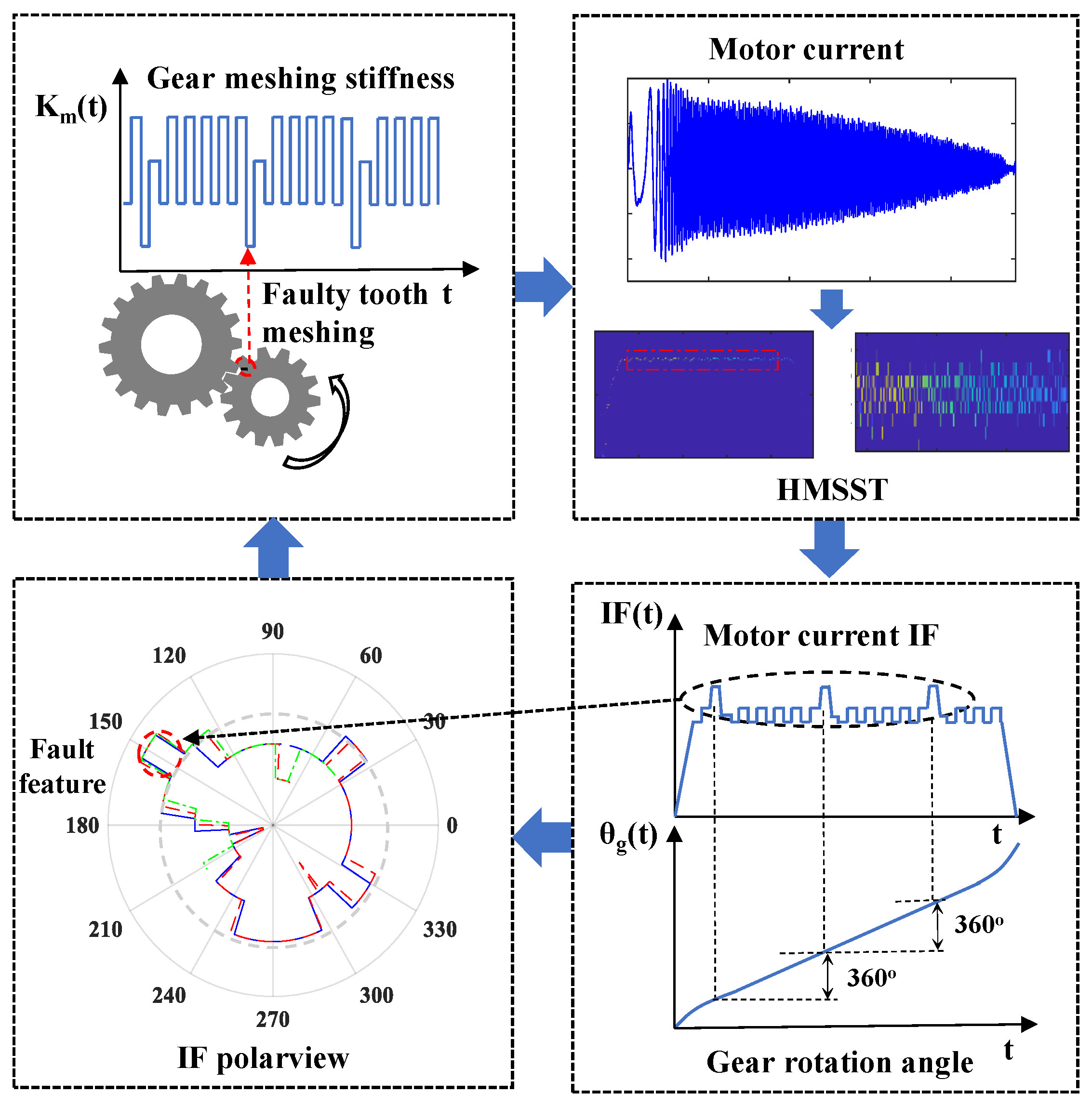
For gearbox faults, the instantaneous stiffness of faulty gear meshing affects the IF of the motor current, and high-resolution TFA highlights the FM features. The occurrence cycles of the fault features are generally the rotation period of a faulty gear and its multiples. Thus, if the motor current IF is expressed in polar coordinates, the faulty FM features will appear repeatedly at certain angle positions in the polarview. In order to improve the visualization of the fault features and weaken the interference of the normal gears, the instantaneous frequency polarview (IFpolarview) is proposed by combining the shaft angle from the servo system and the extracted current IF. This method gathers the fault features with periodicity in a small area of the IFpolarview and does not require searching for anomalous fluctuations based on time intervals on the IF curve, which enhances the visualization of fault features and avoids interference from other factors. The schematic view of the IFpolarview is presented in Figure 1.

Figure 1.
Schematic view of IFpolarview.
In the IFpolarview, the IF of the motor current is represented in polar coordinates, where the radial axis corresponds to the IF magnitude, and the angular axis corresponds to the motor angle. The peaks observed in specific angular intervals of the IFpolarview physically represent the fluctuations in the motor current IF caused by faulty gear meshing. Specifically, when a gear tooth with a fault (e.g., wear, crack, or chip) engages with its mating tooth, contact losses are incurred during gear meshing, resulting in reduced mesh stiffness and transient torque fluctuations. This disturbance will affect the motor current, leading to localized fluctuations in the IF. These fluctuations manifest as peaks in the IFpolarview at angular positions corresponding to the faulty tooth’s engagement. The amplitude and shape of these peaks are directly related to the severity and nature of the gear fault. By analyzing the angular positions and characteristics of these peaks, we can identify the specific gear tooth causing the fault and assess its condition. For example, if a gear has a localized fault on one tooth, a distinct peak will appear in the IFpolarview at the angular position corresponding to that tooth’s engagement. Repeated peaks at the same angular interval (synchronized with the gear’s rotation) further confirm the presence of a fault. This visualization method effectively isolates the fault-related features from other sources of interference, such as misalignment or manufacturing errors, which do not exhibit such synchronized patterns.
The motor angle signal is resampled at the sampling rate of the motor current signal to align the two sequences. The discrete representation of the IF can be expressed as IF(z), z = 1,2,3… Z, where Z denotes the data length. Then, the gear rotation angle can be expressed as θg(z), and the polar radius for plotting the IFpolarview can be expressed as rIF(θg(z)) = IF(θg(z)). If motor current signals of multiple motion periods are acquired, the extracted IFs can be averaged on each whole circle as Equation (19); then, random disturbances can be removed to improve the signal-to-noise ratio (SNR) of the IFpolarview.
where N is the number of all periods, and T is the motion period of the aiming gear.
IFpolarview presents the gearbox faults by displaying the FM synchronized with the faulty gear mesh. This approach mitigates the impact of misalignment and manufacturing errors on spectrum detection and has the uniqueness of gear fault features. The employment of electrical parameters makes IFpolarview suitable for implementation in servo control systems. The detailed processes of IFpolarview are as follows:
- The motor current signals and the motor angles of the servo control system are collected synchronously, the motor angle signal is resampled at the sampling rate of the motor current signal to align the two sequences, and the signals are intercepted according to the motion period of the target component;
- The HMSST is employed for motor current signals to obtain the TFRs with concentrated energy and accurate IF;
- The IF of the motor current is extracted from the TFRs by the maximum modulus method [21,22];
- The motor angle is converted to the rotation angle of the gear to be monitored, which is taken as the angular coordinate, and the IF of the motor current is taken as the radius, so that the polar plot is drawn to obtain the IFpolarview.
An important prerequisite for drawing the IFpolarview is the accurate gear rotation angle, which can be captured conveniently in the servo control system. In planetary gear transmission, the sun gear rotation angle is the motor angle, and the planetary gear rotation angle is obtained by multiplying the sun gear rotation angle by the tooth ratio and subtracting the revolution angle. More importantly, the synchronization of the current signal and the motor angle is a critical issue for an accurate IFpolarview. The motor current and angle should be acquired synchronously, and the two sequences should be aligned by resampling; otherwise, the IFpolarview cannot be made.
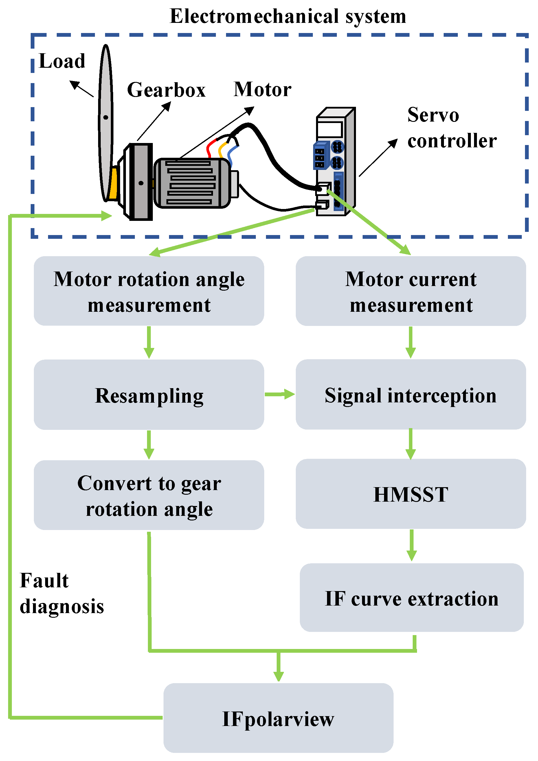
The flowchart of the proposed method in this study is shown in Figure 2.
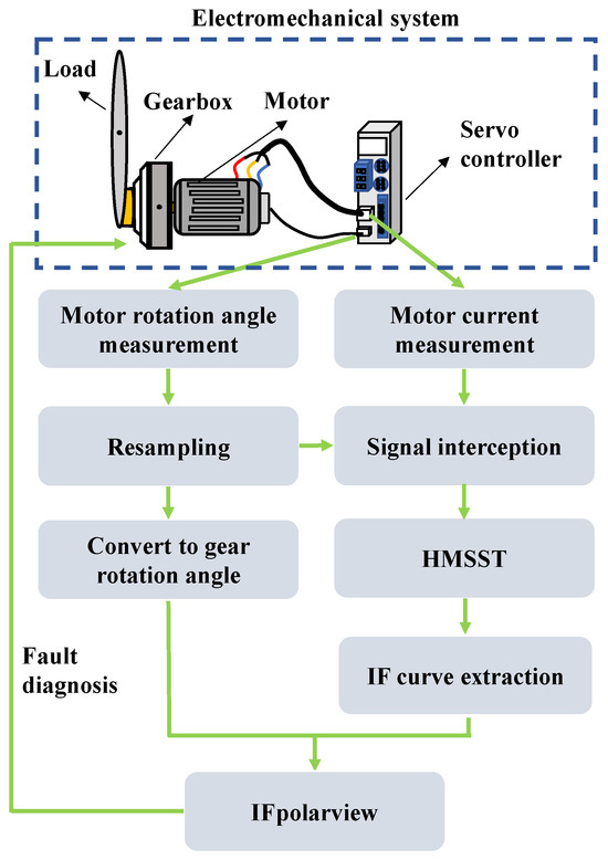
Figure 2.
Flowchart of the proposed method.
4. Simulation
In order to examine the impact of gear fault on motor current, a simulation model with time-varying meshing stiffness of the robot servo joint was established according to the test bench structure in Section 5. For the specific modeling process, please refer to our previous work [23]. The simulation was implemented in MATLAB/Simulink, with a sampling rate of 2560 Hz. The hardware environment for the simulation was Intel Core i7-13650HX + 16GB DDR5 + high speed NVMe SSD. In order to simulate the contact loss due to faulty gear meshing, a periodic decrease in meshing stiffness was set according to the meshing stiffness model in the reference [23] based on the meshing period of the faulty gear meshing. The simulated parameters can be found in Table 1.

Table 1.
Parameters of the simulated robot joint model.
The model replicated a servo joint of the robot, in which the fault was configured as a sun gear single tooth defect. The motor reached an acceleration of 940 r/min within a time frame of 0.3 s, sustaining this velocity from 0.3 s to 2.2 s, before decelerating to a complete stop at 2.5 s. Concurrently, the robotic arm executed a rotation of 90 degrees. The fundamental frequency fs associated with the peak speed was calculated to be 78.33 Hz. According to the frequency calculation method of a planetary gearbox [24], the meshing frequency of the faulty sun gear tooth fg was 15.56 Hz. The swinging of the joint arm created unbalanced loads, resulting in time-varying loads, which was consistent with the experimental conditions. However, no additional noise (e.g., sensor noise, ambient noise, etc.) was artificially added to the simulation in order to evaluate the performance of the proposed method more clearly in a controlled environment. This is the main difference from the experimental conditions.
The simulated motor current is shown in Figure 3a; the modulation phenomenon caused by the gear fault is not evident in the motor currents because of the time-varying load and speed. Figure 3b displays the motor current spectrum of the uniform speed stage. There are fundamental frequency fs and fault sideband frequencies (fs − fg, fs − 2fg and fs + fg) in the spectrum, but the low amplitudes of the sidebands make it difficult to detect gear faults.

Figure 3.
Simulation current signals: (a) motor current and (b) spectrum of motor current signal.
The motor current was analyzed using HMSST and contrasted with other TFA methods. The simulated motor current signal was analyzed by STFT, SST, second-order SST (2-SST) and fourth-order HSST (4-HSST) with the window parameter set to σ = 0.04; the obtained TFRs are depicted in Figure 4a–h. Figure 4a,b show the STFT results, where it is obvious that the SST and HSST show better resolution than the STFT, and FM can be observed in the partial enlargement view, as shown in Figure 4d,f,h. However, the TFR of the SST still shows severe energy divergence. As the order increases, the accuracy of the IF becomes higher, and the time–frequency energy becomes concentrated, but the frequency blurring still exists in Figure 4f,h. To further validate the advantages of the STFT-based SST and its higher-order methods, the results were also compared with that of continuous wavelet transform (CWT), as shown in Figure 4i,j. It can be seen that the results of the CWT are close to the STFT and much worse than those of the SST, 2-SST, and 4-HSST.
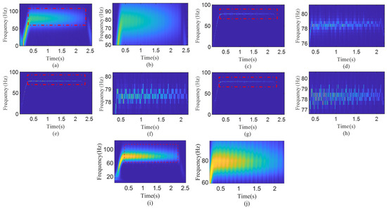
Figure 4.
TFRs of the simulated motor current: (a) STFT, (b) partial enlargement of (a), (c) SST, (d) partial enlargement of (c), (e) 2-SST, (f) partial enlargement of (e), (g) 4-HSST result, (h) partial enlargement of (g), (i) CWT result, (j) partial enlargement of (i).
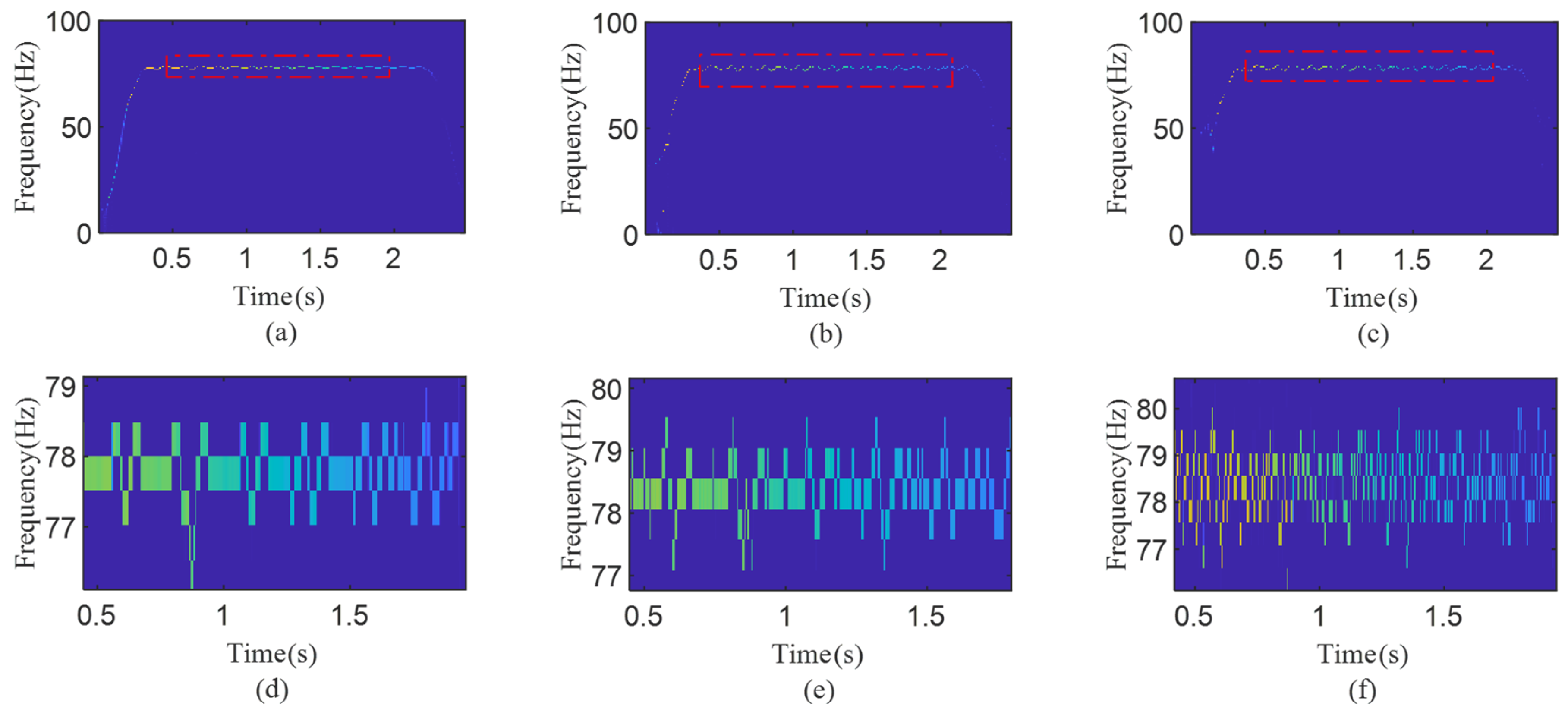
To provide better TFR simply and effectively, [4,3]-HMSST was obtained by squeezing the 4-HSST three times, and the result was compared with the three-times-squeezed SST (3-MSST) and the second-order 3-MSST, as shown in Figure 5a–f. The comparison between Figure 5f and Figure 4h demonstrates that the [4,3]-HMSST provides a more energy-concentrated TFA result than the 4-HSST. It can be observed that the [4,3]-HMSST has the highest time–frequency resolution and modulation amplitude by comparing the partial enlargement of the 3-MSST, second-order 3-MSST, and [4,3]-HMSST, as shown in Figure 5d–f.
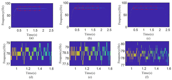
Figure 5.
TFRs of the simulated motor current: (a) 3-MSST, (b) second-order 3-MSST, (c) [4,3]-HMSST, (d) partial enlargement of (a), (e) partial enlargement of (b), (f) partial enlargement of (c).
In order to quantify the difference between the estimated IF and the desired IF, an error index was introduced to demonstrate the advantages of HMSST. The error index can indicate the accuracy of the TFR results and is calculated as
where Id is the desired IF, and Ie is the estimated IF.
The results of the estimation error and computation time are shown in Table 2. The computation times of the STFT and SST are shorter, but the errors are more than 4%, which are larger than those of the other methods. The 4-HSST, 3-MSST, and second-order 3-MSST have errors between 3% and 4%, which indicate that the higher-order or multi-squeeze operation can restore the true frequency of the signal. However, the complicated calculation also increases the computational burden. Although the HMSST increases the calculation burden due to higher-order analyses and multiple iterations, the optimal TFR and smallest error can be obtained. Therefore, the HMSST has great application value for complex working conditions that require high-precision analysis, such as an off-line or timing monitoring system of industrial robots.
Table 2.
Error index and computation time of different TFA methods.
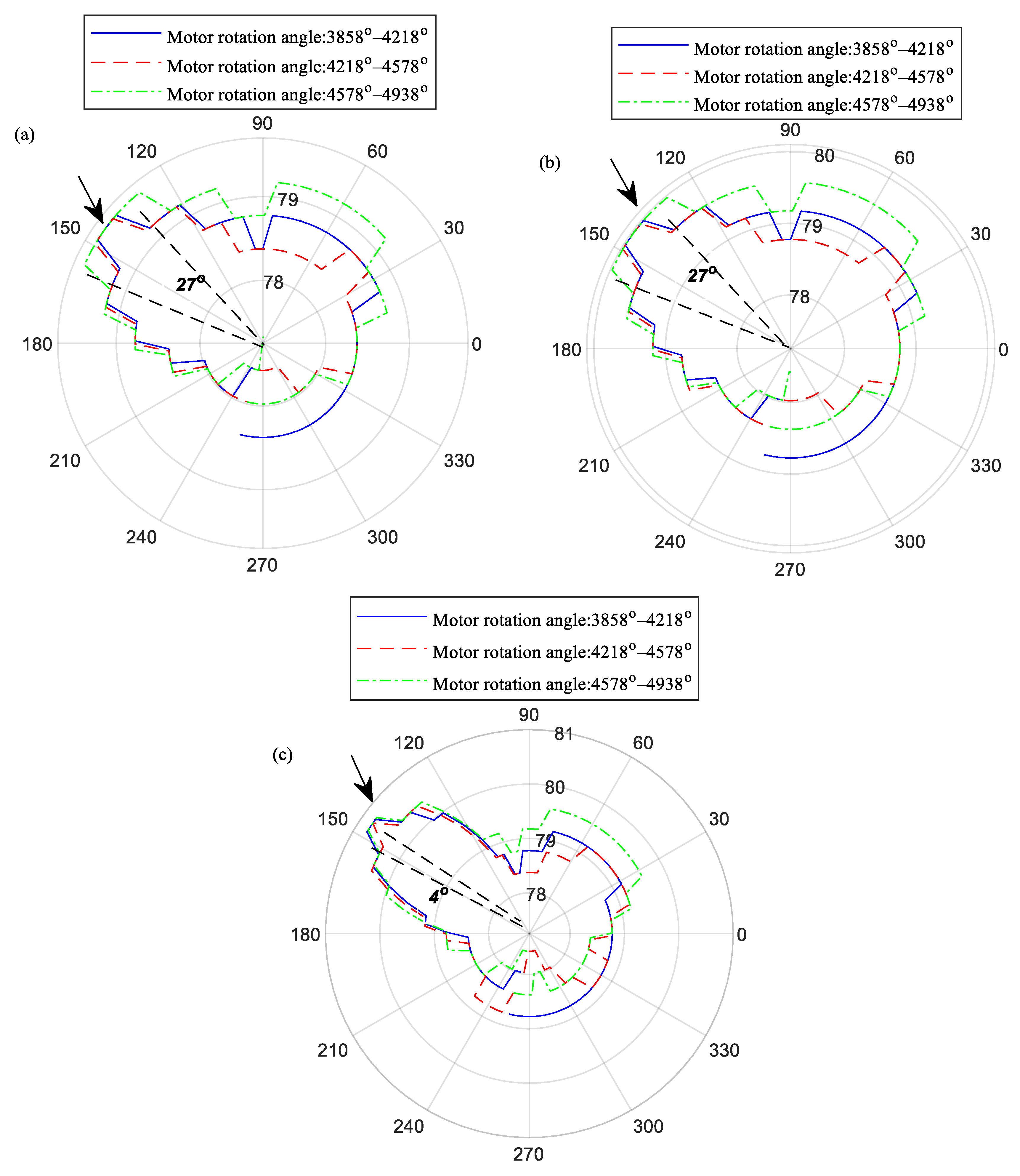
To demonstrate the IF fluctuations induced by the changes of meshing stiffness of the faulty gear, the current IF of three cycles of the motor shaft (3858°–4938°) are intercepted and represented in IFpolarview. Three IFpolarviews based on 3-MSST, 2-order 3-MSST and [4,3]-HMSST are shown in Figure 6a–c. One motor rotation period produces one prominent IF fluctuation, and the fluctuations of three rotation periods coincide at 143° in IFpolarview, which are aligns with the simulated meshing period of the defective gear. As illustrated in in Figure 6a,b, the three fault fluctuations amplitude of the time-frequency ridges of 3-MSST and 2-order 3-MSST are below 80 Hz, and the angle distribution range of fluctuations reaches 27°. While the time-frequency ridge of [4,3]-HMSST in Figure 6c exceeds 80 Hz with an angular distribution range of 4°. It is obvious that the [4,3]-HMSST shows fault features that are more consistent with the transient characteristics of the faulty gear mesh, which illustrates the advantages of IFpolarview based on HMSST in extracting gear fault features.
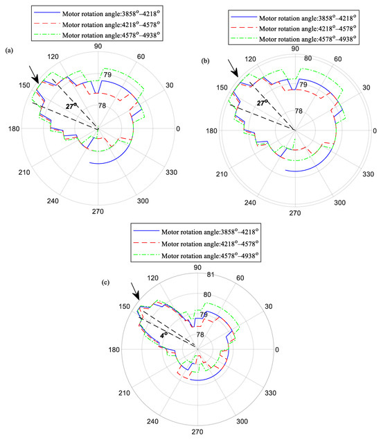
Figure 6.
IFpolarviews: (a) IF of 3-MSST, (b) IF of second-order 3-MSST, (c) IF of [4,3]-HMSST.
5. Experimental Verification
5.1. Experiment Setup
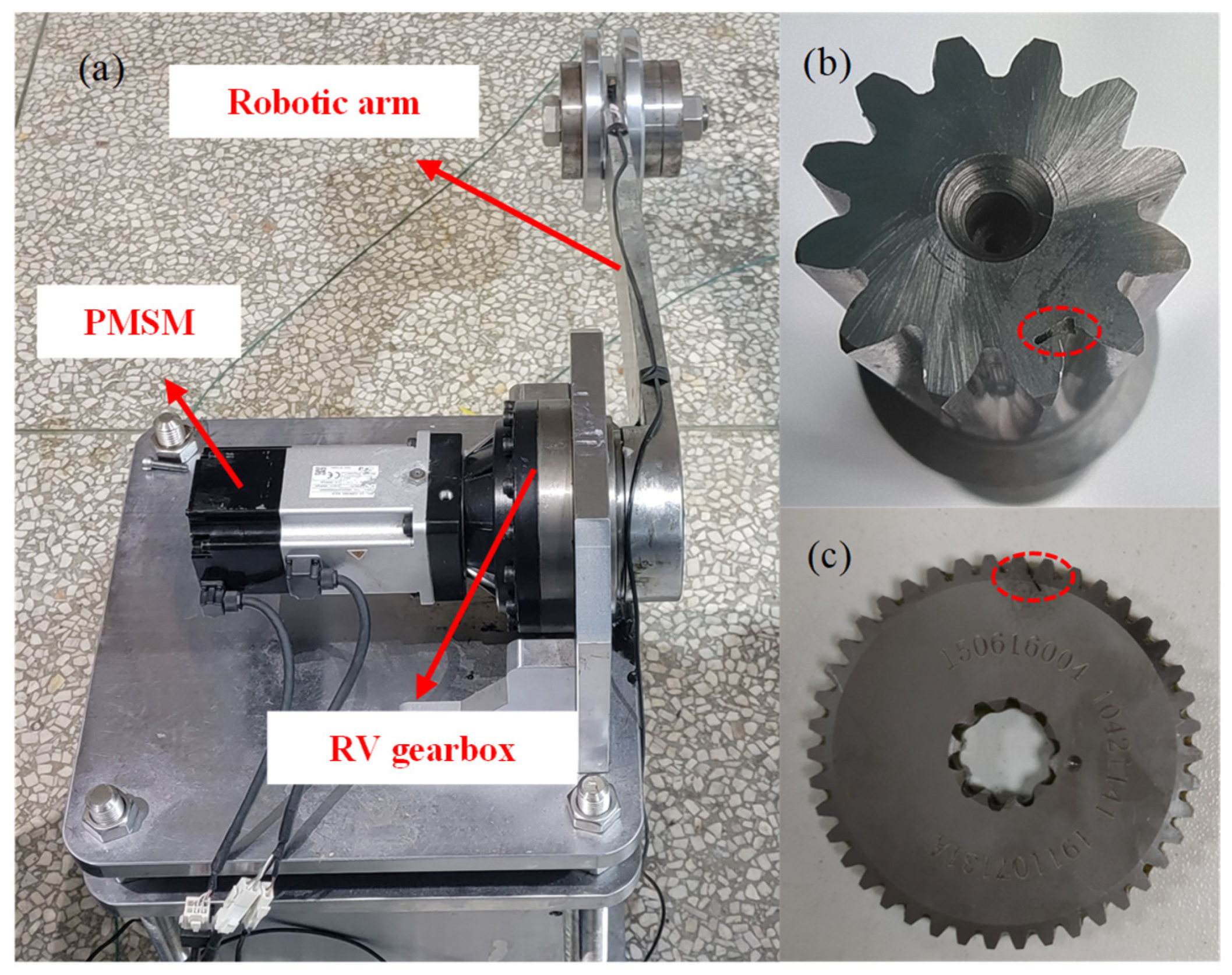
This study constructed a servo joint test bench containing a servo motor, RV gearbox, and robotic arm. The entire setup and the gear faults of an RV gearbox are shown in Figure 7, and the number of planetary gears was two. The motor currents were captured by NI9234 at a 2560 Hz sampling rate. The motor angle was acquired at the sampling rate of 500 Hz by communicating with the controller.
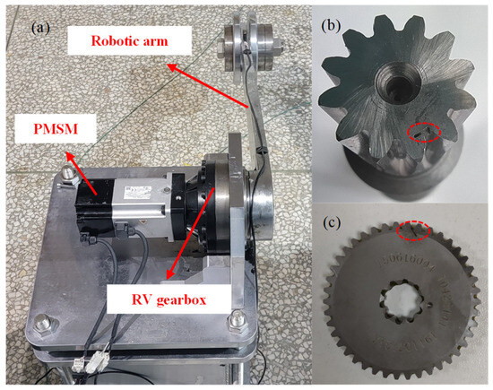
Figure 7.
Experimental setup: (a) servo joint test bench (b) sun gear single tooth root crack, (c) planetary gear single tooth root crack.
Two sets of experiments were conducted: one focusing on local gear fault assessments involving single tooth root cracks in both the sun gear and planetary gear and the other focused on diagnosing the fault of a fatigued RV gearbox.
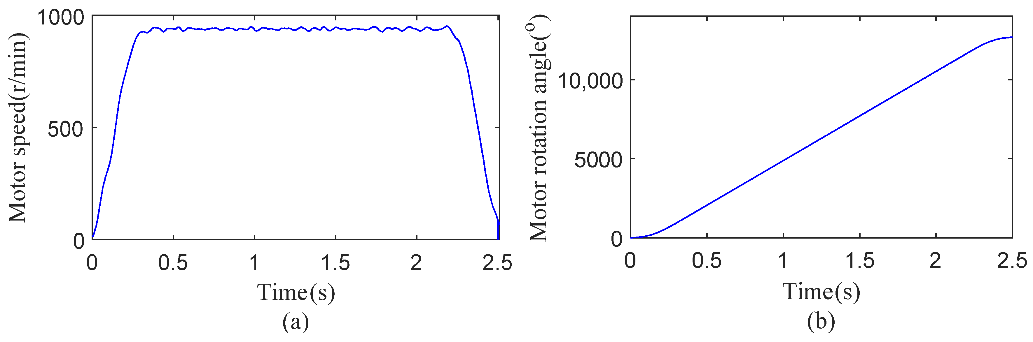
The motor drove the robotic arm to reciprocate 90° as a motion period. The speed and the motor rotation angle are shown in Figure 8. In the constant speed phase, fs = 78.33 Hz. The meshing frequencies for the defective sun gear and planetary gear teeth were fsun = 15.56 Hz and fplan = 4.48 Hz, respectively.
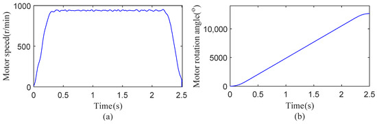
Figure 8.
Motor rotation speed and angle profile for one cycle: (a) motor speed (b) motor rotation angle.
5.2. Motor Current Analysis of Localized Gear Faults
Figure 9a,b show the motor current signals of one arm period in the two gear local fault experiments. The motor current’s amplitude changed over time due to variations in acceleration and deceleration, as well as gravity loads that were dependent on the angle.
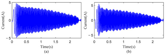
Figure 9.
Motor current signals: (a) sun gear single tooth root crack, (b) planetary gear single tooth root crack.
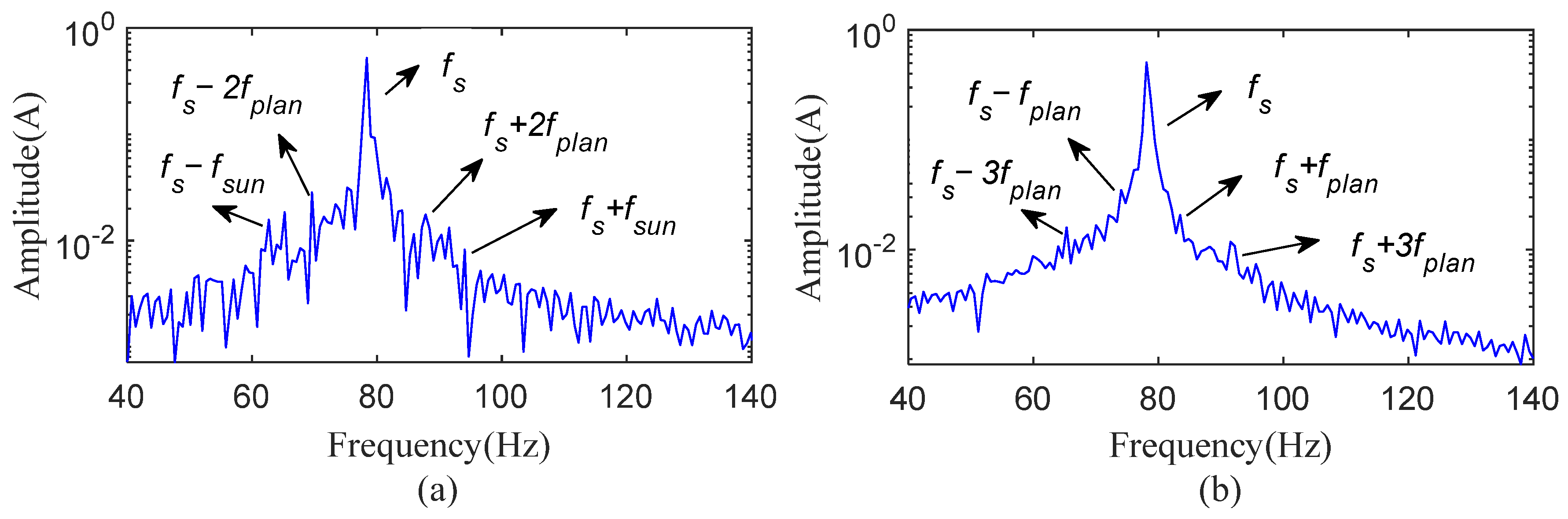
Figure 10 displays the motor current spectrums in steady state from 0.3 s to 2.2 s. In Figure 10a, the spectrum for a sun gear with a single tooth root crack reveals sidebands (fs − fsun and fs + fsun) related to the meshing frequency of the defective sun gear. However, it also includes sidebands (fs − 2fplan and fs + 2fplan) linked to the meshing frequency and harmonics of a faulty planetary gear, complicating the identification of the sun gear fault alone. In Figure 10b, the spectrum for a planetary gear with a single tooth root crack shows sidebands (fs − fplan, fs − 3fplan, fs + fplan, and fs + 3fplan) associated with the meshing frequency of the defective planetary gear tooth. However, the low amplitudes of these frequencies make it difficult to diagnose the planetary gear defect.
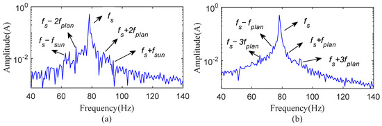
Figure 10.
Spectrum of motor currents: (a) sun gear single tooth root crack, (b) planetary gear single tooth root crack.
To obtain the faulty FM of motor currents, the HMSST of the two current signals were carried out and compared with the other TFA methods. The window parameter was set to σ = 0.04. For the planetary gear single tooth root crack experiment, the motor current signal was analyzed by the 3-MSST, second-order 3-MSST, and [4,3]-HMSST, respectively. The results are displayed in Figure 11a–f. From the partial enlarged views, the time–frequency energies of 3-MSST were concentrated, but the frequency resolution was poor. In comparison, the second-order 3-MSST improved the frequency estimation accuracy, but there was ambiguity in the time–frequency results. The [4,3]-HMSST combined the advantages of both and showed the highest time–frequency resolution and modulation amplitude due to its precise IF estimation, as presented in Figure 11f.

Figure 11.
TFRs of the motor current of planetary gear single tooth root crack: (a) 3-MSST, (b) second-order 3-MSST, (c) [4,3]-HMSST, (d) partial enlargement of (a), (e) partial enlargement of (b), (f) partial enlargement of (c).
In order to quantify the performance of the three TFA methods, their Rényi entropy values were calculated, as shown in Table 3. The Rényi entropy diverges from the Shannon entropy by introducing a tunable order to adjust the sensitivity to signal variations. This parametric flexibility enables it to capture localized energy aggregation patterns in non-stationary signals while mitigating noise interference more effectively than Shannon entropy. The formula for Rényi entropy is
where α represents the order of Rényi entropy. α can be adjusted according to the characteristics of the actual signal, thus reflecting more accurately the energy distribution of the signal in the time–frequency plane. In this study, the value of α was set to 3.
Table 3.
Rényi entropy of TFA methods.
A smaller value of Rényi entropy represents a more concentrated energy of the TFR [20]. It can be seen that the value of [4,3]-HMSST was the smallest, implying that it obtained the optimal TFR.
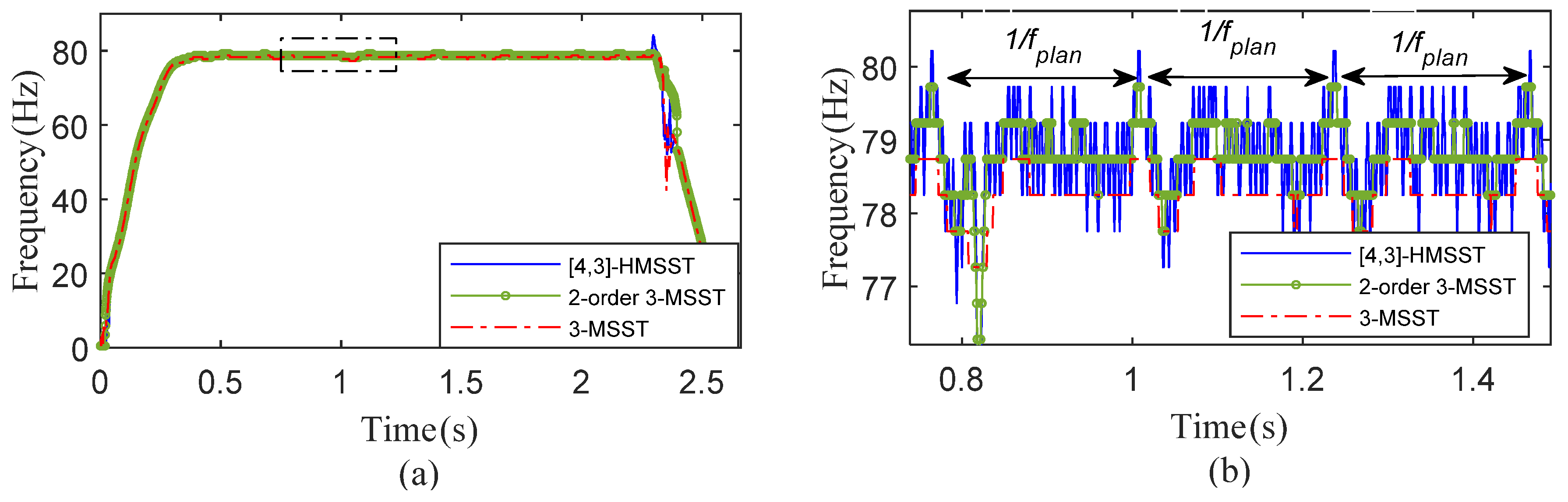
The IFs of the three methods were extracted and compared, as shown in Figure 12. The IFs showed large fluctuations at 2.2 s; the reason is that the weak time–frequency energy at this stage leads to the error of the ridge extraction using the maximum modulus. It can be noticed from Figure 12b that all three IFs showed transient fluctuations with the planetary gear fault period, but the IF of [4,3]-HMSST demonstrated the best frequency resolution and the highest fluctuation amplitude.
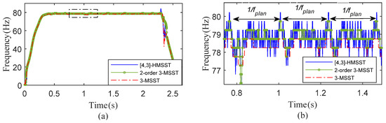
Figure 12.
IFs of the motor current of planetary gear single tooth root crack: (a) results of [4,3]-HMSST, second-order 3-MSST, and 3-MSST, (b) partial enlargement of (a).
Based on the high resolution of the [4,3]-HMSST, the IFpolarview was utilized to display the planetary gear fault. The planetary gear rotation angle was adopted as the reference, and the IF of the planetary gear rotation for three cycles (1354°–2434°) was intercepted; the result is presented in Figure 13. In the RV gearbox, the planetary gear meshed only with the sun gear; so, the faulty tooth meshed once per cycle, resulting in one transient fluctuation. Notably, when calculating the planetary gear angle based on the motor angle, the position of the faulty tooth mesh was different each rotation period because the planetary gear revolved around the sun gear. Therefore, the revolution angle should be subtracted from the angle reference, so that each fault fluctuation is displayed at the same position. Three fault transient fluctuations were shown at 342° in the IFpolarview, which indicated the location of the fault. When the planetary gear was rotated to this angular position, the faulty tooth engaged, resulting in a transient decrease in the meshing stiffness, which caused a fluctuation in the current IF. In contrast to searching for weak fault sidebands in the motor current spectrum, the IFpolarview has the advantage of intuition and accuracy. The unique periodicity and repeatability of fault features in the current IF avoids the interference of random errors.
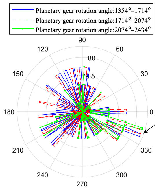
Figure 13.
IFpolarview of planetary gear single tooth root crack.
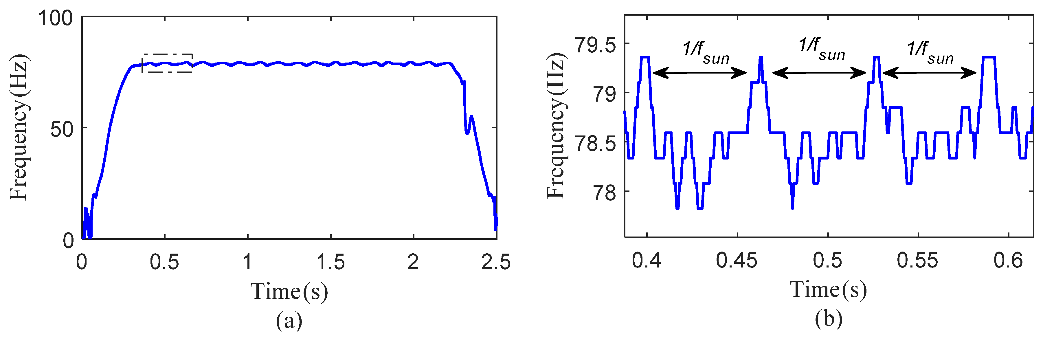
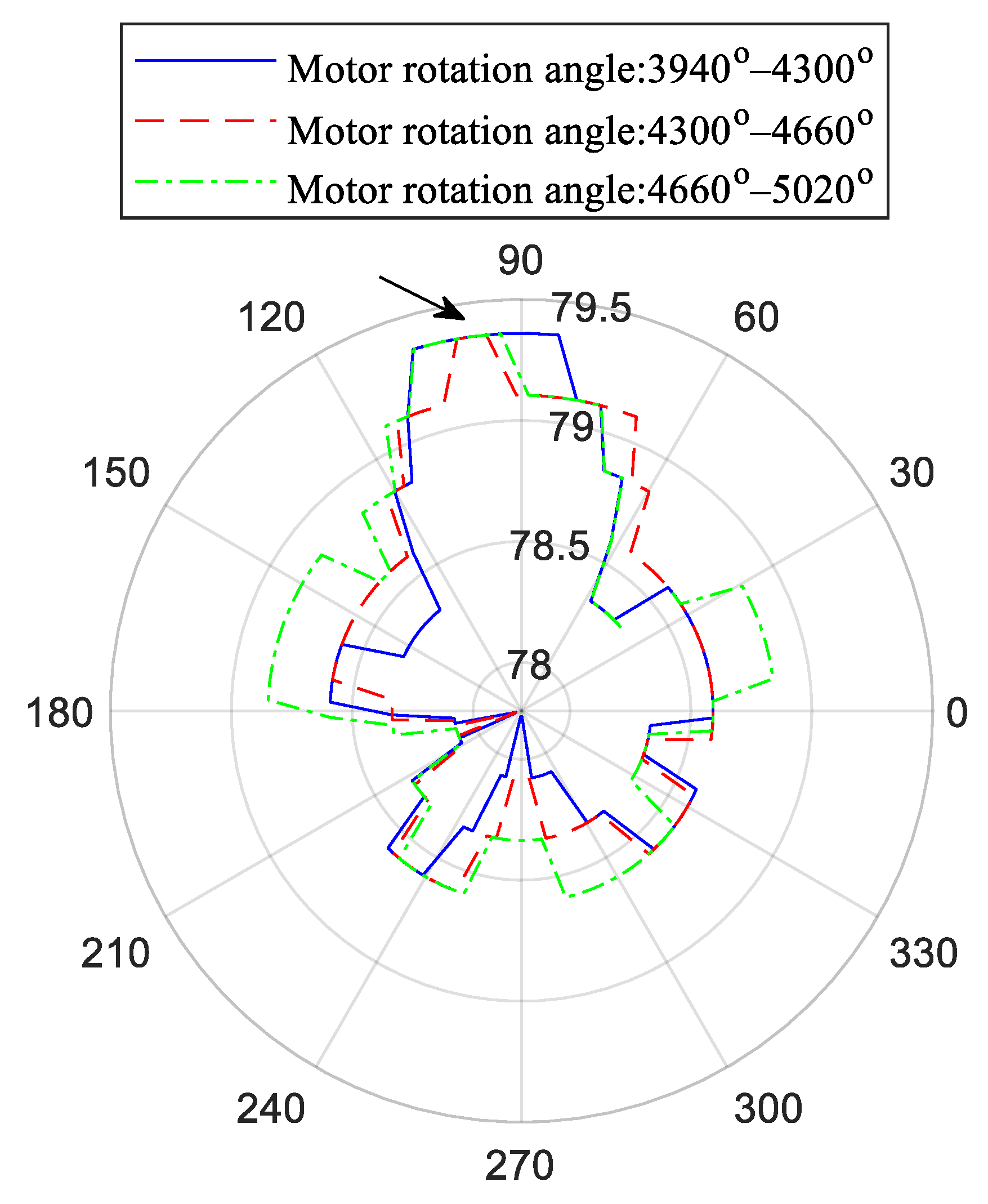
For the local fault experiment of the sun gear, Figure 14a,b show the IF extracted based on the [4,3]-HMSST. The transient fluctuations on the IF aligned with the meshing period of a defective gear tooth. The rotation angle of the motor was used as the angle reference for the IFpolarview, and the IF of three cycles (3940°–5020°) of the sun gear was intercepted; the obtained graph is Figure 15. In every rotation period, the sun gear fault produced a high-amplitude frequency fluctuation at 98° of the IFpolarview. This is because the sun gear fault tooth meshed with the planetary gear at this angular position, which led to the decrease in the meshing stiffness and the transient fluctuation. The ideal IFpolarview should show the transient IF fluctuations in two positions, because the faulty sun gear engaged each of two planetary gears in one cycle. However, due to the installation and manufacturing errors, the two planetary gears are subjected to different loads. As a result, a prominent FM is produced when the sun gear was meshed only with one of the planetary gears.
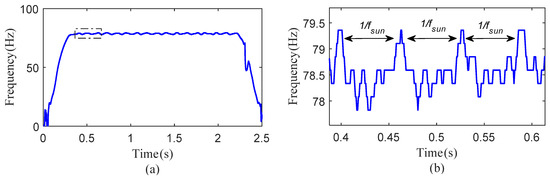
Figure 14.
IF of the motor current of sun gear single tooth root crack: (a) results of [4,3]-HMSST, (b) partial enlargement of (a).

Figure 15.
IFpolarview of sun gear single tooth root crack.
5.3. Motor Current Analysis of Fatigue RV Gearbox
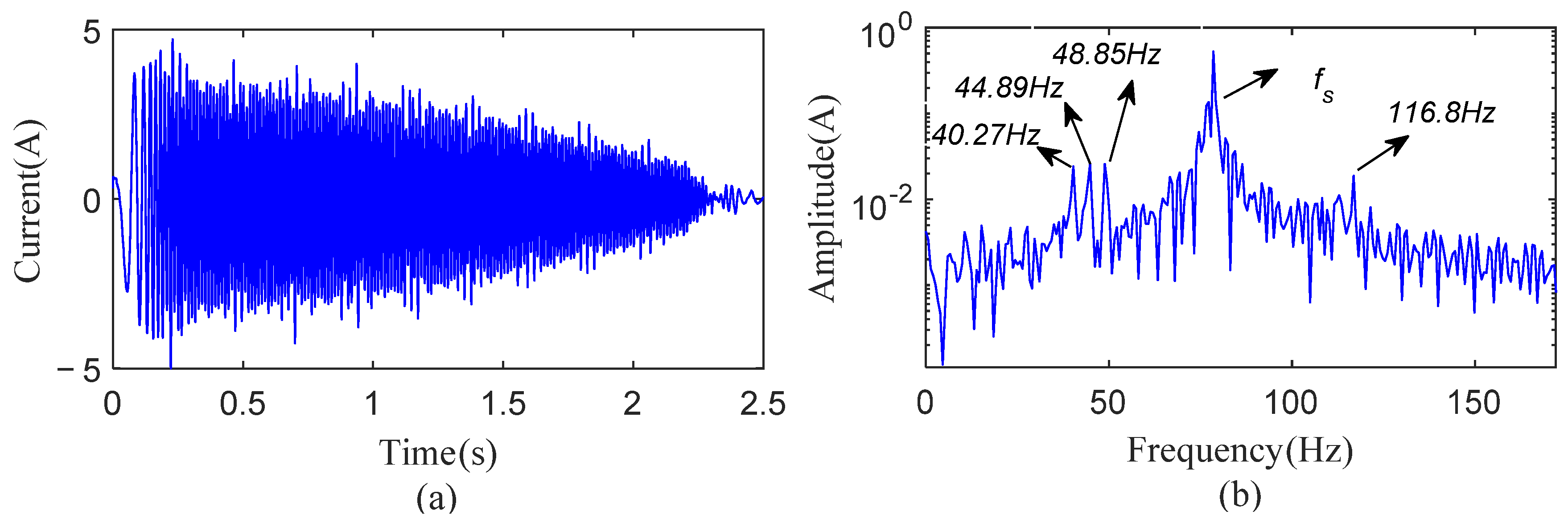
In order to simulate the long-term operation of an RV gearbox under variable speed and load conditions, fatigue experiments were carried out on the servo joint test bench for one year. Figure 16 shows the motor current and its spectrum of one period. The current spectrum showed several distinct sidebands around the power supply frequency fs, 116.8 Hz, 48.85 Hz, 44.89 Hz, and 40.27 Hz, respectively. These sidebands were separated from fs by 38.24 Hz, 29.71 Hz, 33.67 Hz, and 38.29 Hz, which are not equal to the meshing frequencies of a faulty sun gear or a planetary gear tooth.

Figure 16.
Current signal of fatigue RV gearbox: (a) current signal, (b) spectrum of current signal.
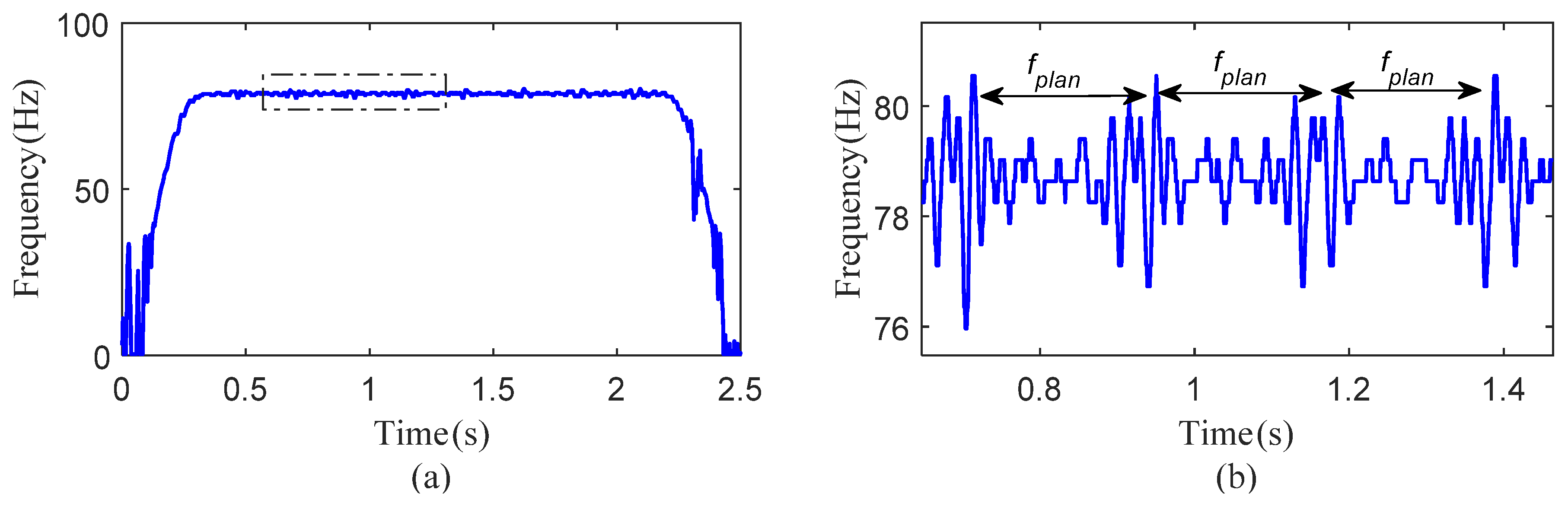
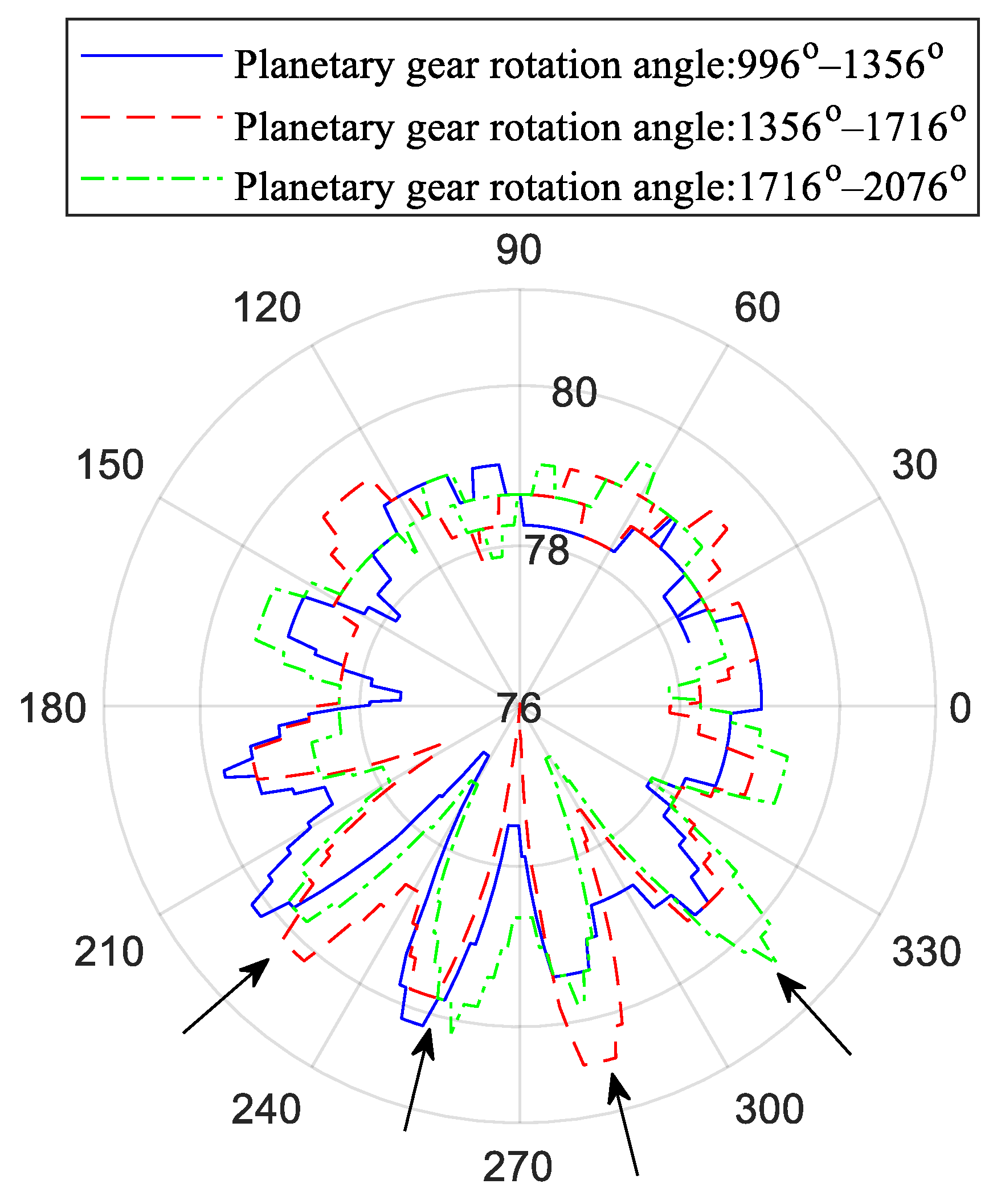
The current IF extracted based on [4,3]-HMSST is shown in Figure 17, where the local enlargement shows the modulation by the meshing frequency of a defective planetary gear tooth. The rotation angle of the planetary gear was adopted as the angle reference, and three cycles (996°–2076°) were intercepted to draw the IFpolarview, as shown in Figure 18. Each rotation period of the planetary gear had transient fluctuations at four positions of 221°, 256°, 282°, and 315° on the IFpolarview, which indicated multi-tooth faults of the planetary gear.
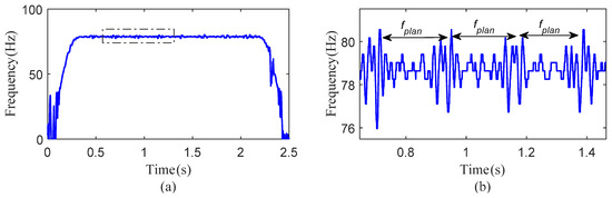
Figure 17.
IF of the motor current of fatigue RV gearbox: (a) results of [4,3]-HMSST, (b) partial enlargement of (a).
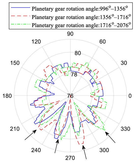
Figure 18.
IFpolarview of fatigue RV gearbox.
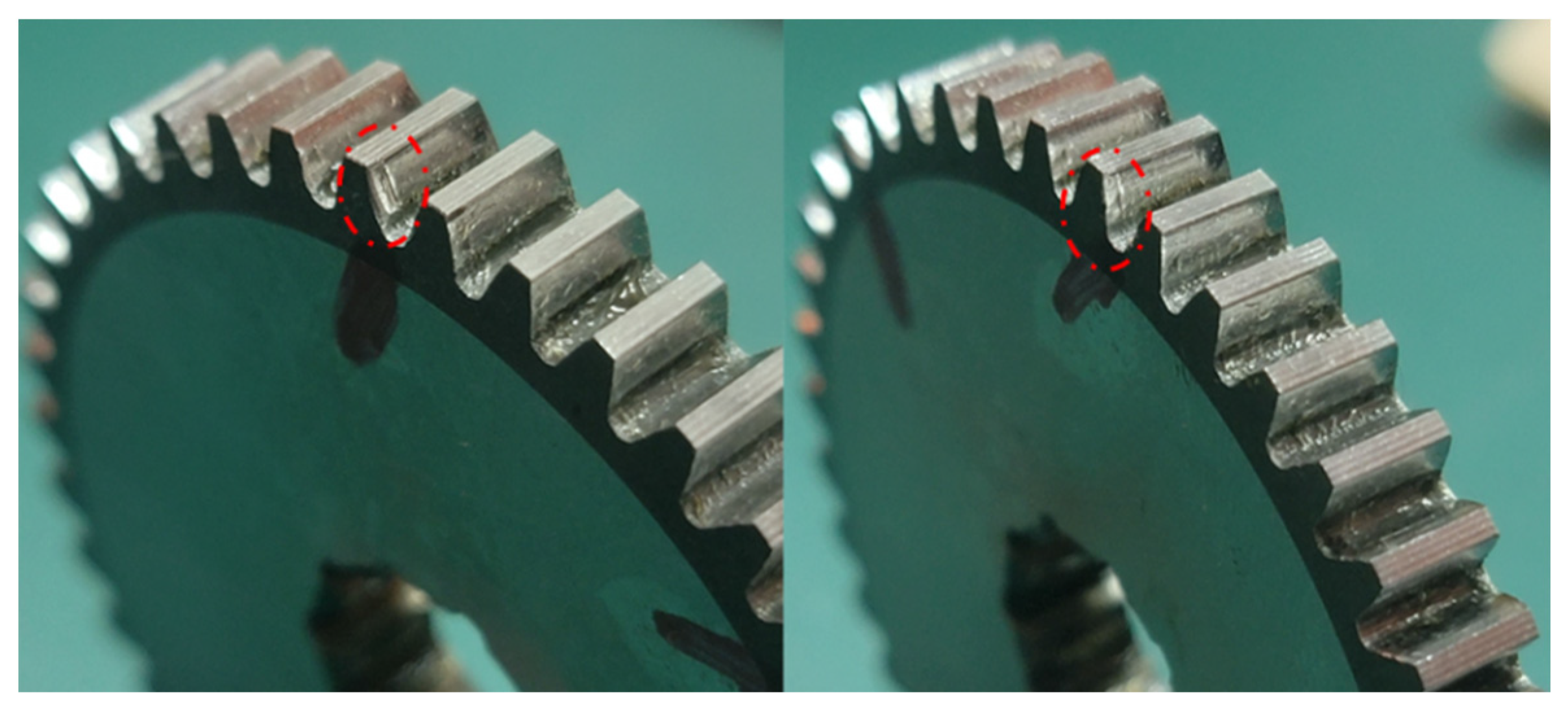
Based on the results of the IFpolarview, the fatigued RV gearbox was disassembled. Different degrees of teeth wear were found on the planetary gear tooth surfaces, as seen in Figure 19, which agrees with the analysis results and proves the effectiveness of IFpolarview in practical applications.
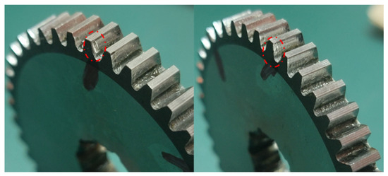
Figure 19.
Multi-tooth wear faults of planetary gear in fatigue RV reducer.
The experimental analysis presented above shows that the approach suggested in this research yields outstanding detection outcomes. The HMSST-based IF contains abundant and significant fault characteristics, and IFpolarview shows the unique gear fault characteristics in an intuitive way. Both local gear faults and multi-tooth faults can be diagnosed by the IFpolarview.
6. Discussion
The simulation and experimental results highlight three key advancements of the proposed method:
Superior Time–Frequency Resolution: HMSST achieves a 35% reduction in the IF estimation error compared to the SST (2.51% vs. 4.53%) and a 9% improvement in Rényi entropy over the 3-MSST (9.13 vs. 9.96), demonstrating its ability to resolve transient fault features obscured by noise and load variations.
Enhanced Fault Visualization: The IFpolarview diagnoses gear faults by detecting anomalous fluctuations that occur repeatedly at an angle (e.g., 342° for planetary gear cracks and 98° for sun gear defects), reducing the diagnostic ambiguity caused by spectral sideband interference. This contrasts with traditional methods, where sidebands like fs ± fg are often indistinguishable from harmonics.
Practical Applicability: The method leverages readily available servo system parameters (motor current and angle) without requiring external sensors. Experimental validation on a fatigued RV gearbox successfully identified multi-tooth wear faults (Figure 19), aligning with disassembly findings, proving its reliability in real-world scenarios.
It is worth noting that the proposed method can be extended to the diagnosis of various faults of rotating machinery, such as backlash, bearing faults, and other cases with periodic stiffness variations. As an example, in the case of gear backlash faults, the contact loss occurs at the instant of engagement of the faulty tooth, which generates torque fluctuation and thus affects the motor current. In addition, the meshing of the faulty teeth is periodic, resulting in periodic changes in the current IF. Thus, it is only necessary to convert the angle coordinate of the polarview to the rotation angle of the mechanical part to be monitored, and the health of the mechanical part can be monitored.
7. Conclusions
In the research of electromechanical system fault diagnosis, it is promising to use the motor currents of servo control system to diagnose the transmission components faults. Firstly, the motor current signals were analyzed using the HMSST method, which obtained a better TFR and more accurate IF estimation than the HSST and MSST without increasing the order and difficulty of the algorithm. The HMSST highlighted the FM of the IF at each faulty gear meshing. Comparison of the Rényi entropy values of several methods showed that the HMSST obtained the most energy-focused TFR. Then, the IFpolarview combining IF and the gear angle in polar coordinates diagnosed the gear fault by the transient fluctuations at the angle of the faulty tooth. Finally, experimental verification was conducted on the servo joint test bench, and IFpolarview showed the fault characteristics of the sun gear and planetary gear root cracks accurately. Both local gear faults and multi-tooth faults can be diagnosed by the IFpolarview. The IF extraction method and IFpolarview proposed in this study utilize the motor current and motor angle information, both of which are easily available in the servo control system. More intuitive and reliable diagnosis results are obtained than the sideband detection of the current spectrum.
In practical engineering applications, the HMSST can obtain more accurate transient frequency estimation than traditional time–frequency analysis methods, which can identify potential faults more efficiently and accurately. IFpolarview can provide an intuitive means of fault location, and it does not need engineers to have professional fault diagnosis knowledge, which is of good application value. The method’s diagnostic accuracy may degrade under extreme noise levels or simultaneous multi-fault scenarios, where IF fluctuations overlap. Additionally, planetary gear fault localization requires precise revolution angle compensation, which assumes known gear ratios. Future studies will address these limitations through adaptive noise suppression and unsupervised fault separation techniques.
Author Contributions
Conceptualization, K.X. and S.C.; methodology, K.X.; software, S.C.; validation, S.C.; formal analysis, K.X.; writing—original draft preparation, S.C.; writing—review and editing, K.X. All authors have read and agreed to the published version of the manuscript.
Funding
This work was partially supported by the Scientific Research Fund Project of Yunnan Education Department (Grant NO. 2024J1771) and the Science and Technology Major Project of Yunnan Province (Grant NO. 202002AC080001).
Data Availability Statement
The raw data supporting the conclusions of this article will be made available by the authors on request.
Conflicts of Interest
The authors declare no conflicts of interest.
Nomenclature
| s(t) | single component signal |
| Gs(t,ω) | TFR of STFT |
| ∂tGs(t,ω) | the partial derivative of Gs(t,ω) |
| g(t) | window function |
| σ | window parameter |
| estimated IF | |
| the real part of the estimated IF | |
| δ | the Dirac delta function |
| η, ω | frequency |
| t | time |
| Ts(t,η) | TFR of SST |
| A(t) | signal amplitude |
| ϕ(t) | signal phase |
| FM operator | |
| precise IF | |
| real part | |
| i | imaginary number |
| Nth-order IF estimation | |
| Ts[N] (t,η) | TFR of HSST |
| Ts[N,M] (t,η) | TFR of HMSST |
| RIF | radius in polar coordinates |
| θg | rotation angle |
| Z | signal length |
| N | number of all periods |
| T | motion period of the aiming gear |
| Er | error index |
| RE | Rényi entropy |
| α | order of Rényi entropy |
References
- Cao, Q.; Giustozzi, F.; Zanni-Merk, C.; de Bertrand, F.; Reich, C. Smart condition monitoring for industry 4.0 manufacturing processes: An ontology-based approach. Cybernet. Syst. 2019, 50, 82–96. [Google Scholar] [CrossRef]
- Zou, Y.Y.; Zhang, Y.D.; Mao, H.C. Fault diagnosis on the bearing of traction motor in high-speed trains based on deep learning. Alex. Eng. J. 2021, 60, 1209–1219. [Google Scholar] [CrossRef]
- Sami, H.; Luca, D.; Alin, A.S. Robot Collisions: A survey on detection, isolation, and identification. IEEE Trans. Robot. 2017, 33, 1292–1312. [Google Scholar] [CrossRef]
- Xu, K.; Wu, X.; Wang, D.; Liu, X. Electromechanical coupling modeling and motor current signature analysis of bolt loosening of industrial robot joint. Mech. Syst. Sig. Process. 2023, 184, 109681. [Google Scholar] [CrossRef]
- Lu, Z.; Li, L.; Zhang, C.; Zhao, S.; Gong, L. Fault Feature Extraction Based on Variational Modal Decomposition and Lifting Wavelet Transform: Application in Gear of Mine Scraper Conveyor Gearbox. Machines 2024, 12, 871. [Google Scholar] [CrossRef]
- Lei, Y.; Liu, Z.; Lin, J.; Lu, F. Phenomenological models of vibration signals for condition monitoring and fault diagnosis of epicyclic gearboxes. Sound. Vib. 2016, 369, 266–281. [Google Scholar] [CrossRef]
- Nurafnida, A.; Roberto, F. Leakage error compensation in motor current signature analysis for shaft misalignment detection in submersible pumps. IEEE Trans. Instrum. Meas. 2020, 69, 8821–8830. [Google Scholar] [CrossRef]
- Benbouzid, M.E.H. A review of induction motors signature analysis as a medium for faults detection. IEEE Trans. Ind. Electron. 2000, 47, 984–993. [Google Scholar] [CrossRef]
- Blodt, M.; Chabert, M.; Regnier, J.; Faucher, J. Mechanical load fault detection in induction motors by stator current time-frequency analysis. IEEE Trans. Ind. Appl. 2006, 42, 1454–1463. [Google Scholar] [CrossRef]
- Kia, S.H.; Henao, H.; Capolino, G.A. Analytical and experimental study of gearbox mechanical effect on the induction machine stator current signature. IEEE Trans. Ind. Appl. 2009, 45, 1405–1415. [Google Scholar] [CrossRef]
- Kia, S.H.; Henao, H.; Capolino, G.A. Gear tooth surface damage fault detection using induction machine stator current space vector analysis. IEEE Trans. Ind. Electron. 2015, 62, 1866–1878. [Google Scholar] [CrossRef]
- Gao, A.; Feng, Z.; Liang, M. Permanent magnet synchronous generator stator current AM-FM model and joint signature analysis for planetary gearbox fault diagnosis. Mech. Syst. Sig. Process. 2021, 149, 107331. [Google Scholar] [CrossRef]
- Huang, W.; Gao, G.; Li, N.; Zhu, Z. Time-frequency squeezing and generalized demodulation combined for variable speed bearing fault diagnosis. IEEE Trans. Instrum. Meas. 2019, 689, 2819–2829. [Google Scholar] [CrossRef]
- Huang, Y.; Zhang, Q.; Zhong, J.; Chen, Z.; Zhong, S. Parameterized Instantaneous Frequency Estimation Method for Vibration Signal with Nonlinear Frequency Modulation. Machines 2022, 10, 777. [Google Scholar] [CrossRef]
- Cao, H.; Wang, X.; He, D.; Chen, X. An improvement of time-reassigned synchrosqueezing transform algorithm and its application in mechanical fault diagnosis. Measurement 2020, 155, 107538. [Google Scholar] [CrossRef]
- Ingrid, D.; Lu, J.; Wu, H.T. Synchrosqueezed wavelet transforms: An empirical mode decomposition-like tool. Appl. Comput. Harmon. 2011, 30, 243–261. [Google Scholar] [CrossRef]
- Yu, G.; Yu, M.; Xu, C. Synchroextracting transform. IEEE Trans. Ind. Electron. 2017, 64, 8042–8054. [Google Scholar] [CrossRef]
- Yu, G.; Wang, Z.; Zhao, P. Multisynchrosqueezing transform. IEEE Trans. Ind. Electron. 2019, 66, 5441–5455. [Google Scholar] [CrossRef]
- Pham, D.H.; Meignen, S. High-order synchrosqueezing transform for multicomponent signals analysis—With an application to gravitational-wave signal. IEEE Trans. Signal Process. 2017, 12, 3168–3178. [Google Scholar] [CrossRef]
- Bao, W.; Liu, Z.; Liu, S.; Li, F. Application of High-Order Multisynchrosqueezing Transform in Fault Diagnosis. IEEE Trans. Instrum. Meas. 2024, 73, 1–10. [Google Scholar] [CrossRef]
- Carmona, R.A.; Hwang, W.L.; Torresani, B. Characterization of signals by the ridges of their wavelet transforms. IEEE Trans. Signal Process. 1997, 45, 2586–2590. [Google Scholar] [CrossRef]
- Carmona, R.A.; Hwang, W.L. Multi-ridge detection and time-frequency reconstruction. IEEE Trans. Signal Process. 1999, 47, 480–492. [Google Scholar] [CrossRef]
- Xu, K.; Wu, X.; Wang, D.; Liu, X. Error analysis of instantaneous frequency estimation of second-order sst and its application on analyzing gear meshing stiffness from motor current. IEEE Trans. Instrum. Meas. 2024, 73, 1–12. [Google Scholar] [CrossRef]
- Wang, Z.; Guo, Y.; Wu, X.; Na, J. Localized fault detection of sun gears based on windowed synchronous averaging in the angular domain. Adv. Mech. Eng. 2017, 9, 1–10. [Google Scholar] [CrossRef]


Disclaimer/Publisher’s Note: The statements, opinions and data contained in all publications are solely those of the individual author(s) and contributor(s) and not of MDPI and/or the editor(s). MDPI and/or the editor(s) disclaim responsibility for any injury to people or property resulting from any ideas, methods, instructions or products referred to in the content. |
© 2025 by the authors. Licensee MDPI, Basel, Switzerland. This article is an open access article distributed under the terms and conditions of the Creative Commons Attribution (CC BY) license (https://creativecommons.org/licenses/by/4.0/).