Abstract
Considering the elasticity of gear solid bodies, the load applied to gear teeth will force theoretically separated gear teeth to get into engaging state in advance. This phenomenon is named as the extended tooth contact (ETC). Effects of the ETC directly influence the time-varying mesh stiffness of gear pairs and subsequently alter nonlinear dynamic characteristics of gear transmission systems. Time-vary mesh stiffness, considering effects of the ETC, is thus introduced into the dynamic model of the gear transmission system. Periodic motions of a gear transmission system are discussed in detail in this work. The analytical model of time-varying mesh stiffness with effects of the ETC is proposed, and the effectiveness of the analytical model is demonstrated in comparison with finite element (FE) results. The gear transmission system is simplified as a single degree-of-freedom (DOF) model system by employing the lumped mass method. The correctness of the dynamic model is verified in comparison with experimental results. An incremental harmonic balance (IHB) method is modified to obtain periodic responses of the gear transmission system. The improved Floquet theory is employed to determine the stability and bifurcation of the periodic responses of the gear transmission system. Some interesting phenomena exist in the periodic responses consisting of “softening-spring” behaviors, jump phenomena, primary resonances (PRs), and super-harmonic resonances (SP-HRs), and saddle-node bifurcations are observed. Especially, effects of loads on unstable regions, amplitudes, and positions of bifurcation points of frequency response curves are revealed. Analytical results obtained by the IHB method match very well with those from numerical integration.
1. Introduction
As a typical power transmission device, gear transmission systems are extensively employed in industries such as aviation, vehicle engineering, and wind power generation. Due to effects of some factors consisting of material defects, overloads, tooth failures, and installation errors, gear transmission systems are often subjected to complex excitations during operation. Time-varying mesh stiffness, as the main source of internal excitations in gear transmission systems, is usually regarded as a key input of gear vibration and dynamic modeling [1,2,3]. Thus, developing an effective analytical model of time-varying mesh stiffness is the basis of the dynamic modeling and dynamic analysis of gear transmission systems.
Up to now, some methods for calculating time-varying mesh stiffness are being proposed by many researchers, including experimental methods, FE methods, analytical methods, and mixed methods. For the calculation of time-varying mesh stiffness of gear transmission systems, experimental methods are direct and effective strategies. Raghuwanshi et al. [4] proposed the photoelasticity technique to calculate time-varying mesh stiffness of a gear pair, and a comparison between time-varying mesh stiffness obtained by the photoelasticity technique and that from the analytical model demonstrated the effectiveness of the photoelasticity technique. Pandya et al. [5] also employed the photoelasticity technique to obtain time-varying mesh stiffness of a gear pair. Different from experimental methods that require precise and expensive experimental equipments, FE methods can accurately calculate time-varying mesh stiffness of gear transmission systems by using only FE software. Wang et al. [6] obtained the time-varying mesh stiffness of the gear transmission system with high contact ratio by using an FE method. Zhan et al. [7] proposed a new FE method based on the NX 8.5 software, the ANSYS Workbench 14.5 software, and a quasi-static algorithm to determine the time-varying mesh stiffness. Effects of the tip radius and misalignment of the gear pair on the time-varying mesh stiffness are discussed by using the new FE method. Liang et al. [8] proposed three evaluation models of time-varying mesh stiffness by employing a FE method. Compared with experimental methods and FE methods, analytical methods can more flexibly reveal the relationship between gear parameters and time-varying mesh stiffness. In analytical methods, deformations of elastic gears are regarded as a superposition of the elastic component generated by gear teeth and the fillet foundation of gears. Yang et al. [9] developed a potential energy method to calculate time-varying mesh stiffness caused by deformations of teeth; the potential energy method considered tooth deformations under Hertzian contact, bending, and axial compression. Liang et al. [10] developed an improved analytical model of time-varying mesh stiffness by taking the deformation of the fillet foundation and geometric characteristics of the tooth profile into account. Meng et al. [11] proposed an analytical model of time-varying mesh stiffness; time-varying mesh stiffness of gear teeth with different crack lengths can be obtained using the proposed analytical model. Additionally, effects of spalling with different widths, lengths, and locations on time-varying mesh stiffness are discussed. Liu [12] developed an analytical model to predict time-varying mesh stiffness of a single-stage planetary gear train with different degrees of surface wear. Considering the effects of tooth profile modification on time-varying mesh stiffness, Liu et al. [13] established an analytical model of time-varying mesh stiffness. Meng et al. [14] proposed an anisotropic 3D fractal rough tooth surface model using the fractal geometry theory, and developed a revised analytical model of time-varying mesh stiffness based on the anisotropic 3D fractal rough tooth surface model. Tian et al. [15] established a time-varying mesh stiffness model considering elastohydrodynamic lubrication to calculate mesh stiffness of a planetary gear set. Zhou et al. [16] developed an improved analytical model of time-varying mesh stiffness of a gear pair considering root crack. Zhang et al. [17] proposed an improved time-varying mesh stiffness model of a double-helical planetary gear transmission system considering coupling effects of temperature, fluid, and structure. Considering the centrifugal force in a high-speed working condition, Zheng et al. [18] developed an analytical-FEM framework to integrate the centrifugal field into mesh stiffness of high-speed spur gears, and time-varying mesh stiffness of high-speed spur gears can be accurately predicted using the developed model. The extended tooth contact (ETC) effect stemming from the elasticity of a solid body is not considered in an analytical model of time-varying mesh stiffness in the above-mentioned literature. The ETC effect forces theoretically separated teeth get into engagement in advance and increases the actual contact ratio, which will influence time-varying mesh stiffness and further change dynamic characteristics of gear transmission systems. Ma et al. [19] proposed an analytical model to determine time-varying mesh stiffness of a gear pair with tip relief, where the ETC effect, nonlinear contact stiffness, and revised fillet-foundation stiffness were considered. Ma et al. [20] developed an improved analytical model for the calculation of time-varying mesh stiffness of a cracked spur gear; effects of the reduction of fillet-foundation stiffness and the ETC effect were considered.
Dynamic responses of gear transmission systems can be mainly determined by using numerical methods, analytical methods, and semi-numerical and semi-analytical methods based on a dynamic model of the systems. For the calculation of dynamic responses of gear transmission systems, numerical methods are the most simple. Generally, numerical methods for obtaining dynamic responses of gear transmission systems consist of the fourth-order Runge–Kutta (RK) method, the Newmark- method, and the Gill numerical integration. Jiang et al. [21] obtained dynamic responses of a gear transmission system considering multi-frequency excitation by employing the numerical integration, and discussed the primary resonance of the system. Wan et al. [22] determined dynamic responses of a gear transmission system considering translational and torsional vibrations by using the Newmark- method, and analyzed effects of geometric transmission error, bearing stiffness, and mesh stiffness on dynamic responses, and concluded that dynamic responses of the gear transmission system are periodic signals because of the periodic variation of time-varying mesh stiffness. Liu et al. [23] investigated the nonlinear vibration of a multi-meshing gear system considering tooth profile modification by using the numerical integration, and studied effects of tooth profile modification on the nonlinear vibration of the system. Pan et al. [24] calculated dynamic responses of a gear-shaft-bearing transmission system considering some nonlinear factors consisting of time-varying mesh stiffness, fractional backlash, and static transmission error by applying the RK method, and discussed effects of contact temperature, fractional backlash, and random load on dynamic characteristics of the system. However, the above-mentioned investigations on dynamic responses of gear transmission systems using numerical methods only discussed local dynamic characteristics of the systems.
In order to investigate dynamic characteristics of gear transmission systems in detail, global dynamic responses of the systems need to be obtained. Analytical methods, including the multiple-scale (MS) method, are usually employed to calculate global dynamic responses of gear transmission systems. Moradi et al. [25] obtained forced vibration responses of a gear transmission system with backlash nonlinearity by using the MS method, and analyzed primary resonance, super-harmonic resonance, and sub-harmonic resonance based on the responses of the system. Mo et al. [26] investigated primary resonance characteristic and stability of a gear-rolling-bearing system considering time-varying mesh stiffness, transmission error, and backlash by employing the MS method, and discussed effects of damping, time-varying mesh stiffness, and load on the primary resonance of the system. In the case of determining dynamic responses, the harmonic balance (HB) method and the IHB method belong to the semi-numerical and semi-analytical method, and the HB method and the IHB method are applicable to both strong nonlinear systems and weak nonlinear systems. Bruzzone and Rosso [27] proposed two models to analyze gear dynamics: dynamic overloads caused by meshing can be estimated by the first model with a one-dimensional approach, and the second model includes flexibilities of shafts, bearings, and the gearbox housing. Bruzzone et al. [28] analyzed the dynamic response of a spur gear pair using a refined finite element model. Nonlinear phenomena such as hysteretic jumps, sub-harmonic resonance, and super-harmonic resonance are predicted by the proposed model. Bruzzone et al. [29] estimated deflections, load sharing attributes, and contact conditions of meshing teeth in a spur gear transmission system based on a three-dimensional model. Oliveri et al. [30] predicted the dynamic effect of a parametric model of gear engagement using the HB method, and investigated contributions of the actual static transmission error and the contact ratio on gear dynamics. Alshyyab et al. [31] studied the sub-harmonic resonance of a multi-meshing gear transmission system by using the HB method, and predicted period-doubling motions that cause the system get into chaotic motions. Hou et al. [32] calculated nonlinear dynamic responses of a spur gear pair with fractional-order backlash under the combined action of internal and external excitations by applying the IHB method, and investigated effects of parameters on vibration characteristics including amplitudes of resonance and frequencies of resonance.
In this work, the analytical model of time-varying mesh stiffness is formulated to bridge the gap between the extended tooth contact (ETC) and nonlinear dynamics of the gear transmission system, and verification of its effectiveness is performed. The dynamic model of the gear transmission system considering time-varying mesh stiffness is demonstrated in comparison with experimental results. Global dynamic responses of the gear transmission system are accurately determined by using the IHB method. The stability and bifurcation of nonlinear dynamic responses are analyzed by the improved Floquet theory. In particular, effects of loads on amplitudes, unstable regions, and positions of bifurcation points of frequency response curves are revealed in detail.
Primary goals of this work are to investigate the nonlinear vibration of the gear transmission system considering effects of the ETC and analyzed effects of loads on amplitudes, unstable regions, and positions of bifurcation points of frequency response curves. The rest of this paper is organized as follows: The analytical model of time-varying mesh stiffness is proposed, and ordinary differential equations governing the motion of the gear transmission system are formulated using Newton’s second law in Section 2. The IHB method is modified to determine dynamic responses of the gear transmission system in Section 3. The stability and bifurcation of dynamic responses are examined by employing the improved Floquet theory in Section 4. Jump phenomena, “softening-spring” characteristics, bifurcation behaviors, and resonances of the gear transmission system are discussed in Section 5, and effects of loads on amplitudes, unstable regions, and positions of bifurcation points of frequency response curves are revealed. Primary conclusions of this work are presented in Section 6.
2. Modeling of the Gear Transmission System and Time-Varying Mesh Stiffness
Time-varying mesh stiffness is one of primary parametric excitations of gear transmission systems; the analytical model of time-varying mesh stiffness is proposed. Dynamic models of gear transmission systems are the basis of analyzing nonlinear dynamic behaviors of the systems. The single-DOF dynamic model of the gear transmission system with time-varying mesh stiffness is developed by using the lumped mass method.
2.1. Analytical Model of Time-Varying Mesh Stiffness
As the main source of high-frequency internal excitations of gear transmission systems, the derivation of an accurate model of time-varying mesh stiffness is an important procedure in the process of modeling. In a number of published studies, the time-varying mesh stiffness between two engaging gears is considered to have no relation to effects of the ETC. Yang et al. [33] and Liu et al. [34] proposed an analytical model of time-varying mesh stiffness that is not related to effects of the ETC.
In the process of engaging gear pairs, deformations of tooth pairs will cause tooth pairs get into engaging state in advance and result in tooth pairs getting out engaging state in delay, which extend the contact duration of gear pairs. This phenomenon is named as the extended tooth contact (ETC) [19] and will influence time-varying mesh stiffness. Deformations of tooth pairs are dominated by loads acting on engaging gear pairs. Effects of the ETC on time-varying mesh stiffness are thus considered. Our previous work [35] proposed the analytical model of time-varying mesh stiffness considering effects of the ETC. In order to clarify, the analytical model of time-varying mesh stiffness with effects of the ETC is briefly introduced on the basis of the literature [35]. It should be noted that the proposed analytical model of time-varying mesh stiffness can be implemented with a fast numerical method, which removed restrictions of classical fillet-foundation formulas and covered both thick-walled and thin-walled gears.
The flexibility of a gear pair primarily consists of beam actions of teeth, the elasticity of the fillet foundation, and contact compliances of tooth pairs. The time-varying mesh stiffness of tooth pairs is thus decomposed as the tooth stiffness, the fillet foundation stiffness, and the tooth pair contact stiffness.
A tooth is usually considered an non-uniform cantilever beam. Along the line of action, the reaction of tooth pairs to the local mesh force is denoted as , which is regarded as the superposition of beam actions considering axial compression, bending, and shearing. On the basis of the potential energy method [9], the tooth stiffness is expressed as
where , , and indicate the axial compressive stiffness, the bending stiffness, and the shearing stiffness, respectively, and , , and can be denoted as
respectively. , , E, , and L are the action angle of the local mesh force , the half tooth angle at the base circle, Young’s modulus, Poisson’s ratio, and the tooth width, respectively.
In the process of engaging, the contact compliance of tooth pairs is generated. In order to consider the effects of the load dependency and nonlinearity of tooth contact, the following semi-empirical formula is formulated:
where and denote the Hertzian contact stiffness of a tooth pair and the corresponding contact compliance, respectively.
Considering effects of the deformation response of a tooth and the flexibility of the fillet foundation on tooth deflection, fillet foundation stiffness components are obtained as follows:
where denotes the stiffness corresponding to the local mesh force ; indicates the stiffness corresponding to the local mesh force ; indicates the stiffness corresponding to the local mesh force ; , , and are mesh forces of tooth pairs under different mesh situations; and , , and are external moment arms corresponding to local mesh forces , , and , respectively. Additionally, is the junction arc length between the fillet foundation and the tooth, and , , and are load independency infinite series that are calculated in detail in [35].
For an engaging gear pair, the driving gear is called pinion (marked as “p”), and the driven gear is named gear (marked as “g”). In the process of meshing, deflections of tooth pairs vary with the variation of engaging positions. Recalling Equations (1), (3), and (4), the load–deflection constitutive relation can be obtained as follows:
where is the total elastic deformation of a certain tooth pair, and subscripts and indicate quantities corresponding to tooth pair 1 and tooth pair 2, respectively, which are defined in [35]. Similarly, subscripts and denote quantities corresponding to the pinion and the gear, respectively, and and are local fillet foundation stiffnesses corresponding to tooth pair 1 and tooth pair 2, respectively.
On the basis of the small deformation assumption, the starting angle and the ending angle of the extended tooth contact within one mesh cycle are explicitly expressed as
where and indicate the starting angle and the ending angle of double teeth contact over one mesh cycle, respectively; T is the torque acting on gear pairs; is the base circle radius of the pinion; and is the non-loaded transmission error. Additionally, the Fourier form of time-varying mesh stiffness considering effects of the ETC by using the fast Fourier transformation (FFT) can be obtained as follows:
where , , , , and denote the average mesh stiffness, the Fourier coefficient of the i-th-order harmonic term, the mesh frequency, the contact ratio, and the phase angle of the i-th-order harmonic term, respectively.
2.2. Dynamic Model of the Gear Transmission System
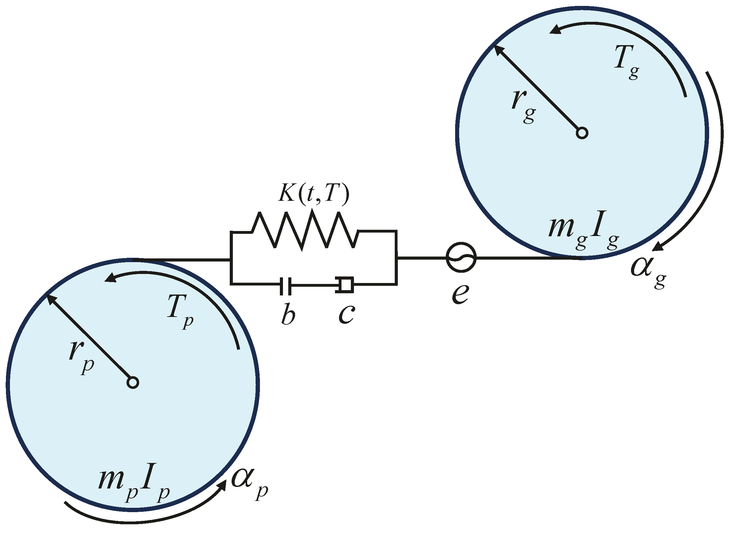
The single-DOF dynamic model of the gear transmission system considering time-varying mesh stiffness is proposed by the lumped mass method, as shown in Figure 1. The driving gear with the inertia , the mass , and the base circle radius and the driven gear with the inertia , the mass , and the base circle radius are modeled as two disks represented by the pinion and the gear, respectively. The mesh between the pinion and the gear is described by the nonlinear displacement function , the viscous damping c, and the time-varying mesh stiffness with effects of the ETC . and are torsional displacements of the pinion and the gear, respectively. and denote torques acting on the pinion and the gear, respectively. Additionally, is the gear backlash. The translational vibration along the line of action and the friction force between engaging teeth are assumed to be negligible [33].
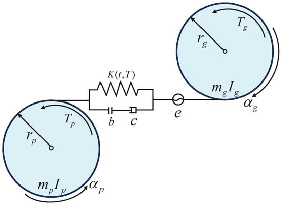
Figure 1.
The single-DOF dynamic model of the gear transmission system considering time-varying mesh stiffness.
By employing Newton’s second law, ordinary differential equations governing motions of the gear transmission system considering time-varying mesh stiffness are formulated as
where is the dynamic mesh force, which can be described as
By defining the dynamic transmission error (DTE) , Equations (8)–(10) can be rewritten as
where the nonlinear displacement function can be expressed as
and
A dimensionless form of Equation (11) can be derived by introducing , , , , and , where is the characteristic length [36].
3. IHB Method for Periodic Responses of the Gear Transmission System
Steady-state periodic responses of the gear transmission system considering time-varying mesh stiffness and a nonlinear displacement function are predicted by utilizing the IHB method. The IHB method is an efficient method for determining periodic or period-doubling responses of smooth systems with general nonlinearities or non-smooth systems with piecewise linearities [37,38], and has been extended to obtain periodic responses of multi-DOF nonlinear systems, such as a two-DOF vehicle system [39] and a three-DOF unit-cell system [40].
By defining a new time variable,
Equation (15) becomes
where is an unknown fundamental frequency, and a prime denotes differentiation with respect to .
The procedure of the IHB method for obtaining periodic responses mainly consists of the incremental process that is the Newton–Raphson iterative procedure to linearize the differential Equation (17) and the process of harmonic balance that is also called the Galerkin procedure [41,42]. In the process of increment, and denote the initial state of vibration; the neighboring state can be obtained by adding increments and to and , respectively.
Substituting Equation (18) into Equation (17), and neglecting high-order terms of increments, the linearized incremental equation can be formulated as
where
is a correction term to prevent the incrementation process from drifting away from actual solutions [43].
The second step of the IHB method is the process of harmonic balance. Under parametric excitation and forced excitation, periodic responses of the gear transmission system can be predicted by expanding in truncated multiple Fourier series and employing the Galerkin procedure [44]. Hence, and its increment can be expressed as
where
in which , , , and are Fourier coefficients; and are numbers of cosine and sine harmonic terms retained, respectively; and p is a positive integer that is introduced to predict possible period-doubling responses [45].
Differentiating Equations (21) and (22) yields
Substituting Equations (21), (22) and (26) into Equation (19) and employing the process of harmonic balance yields
Then a set of linearized equations expressed in terms of and is obtained as follows:
where
in which
Since the time-varying mesh stiffness with effects of the ETC is expressed as
the matrix and the vector can be divided into following three parts, respectively:
where
Calculations of the matrix and the vector are different with the mass matrix or the damping matrix due to the nonlinear displacement function contained in and . The detailed formulation process of and is provided in Appendix A.
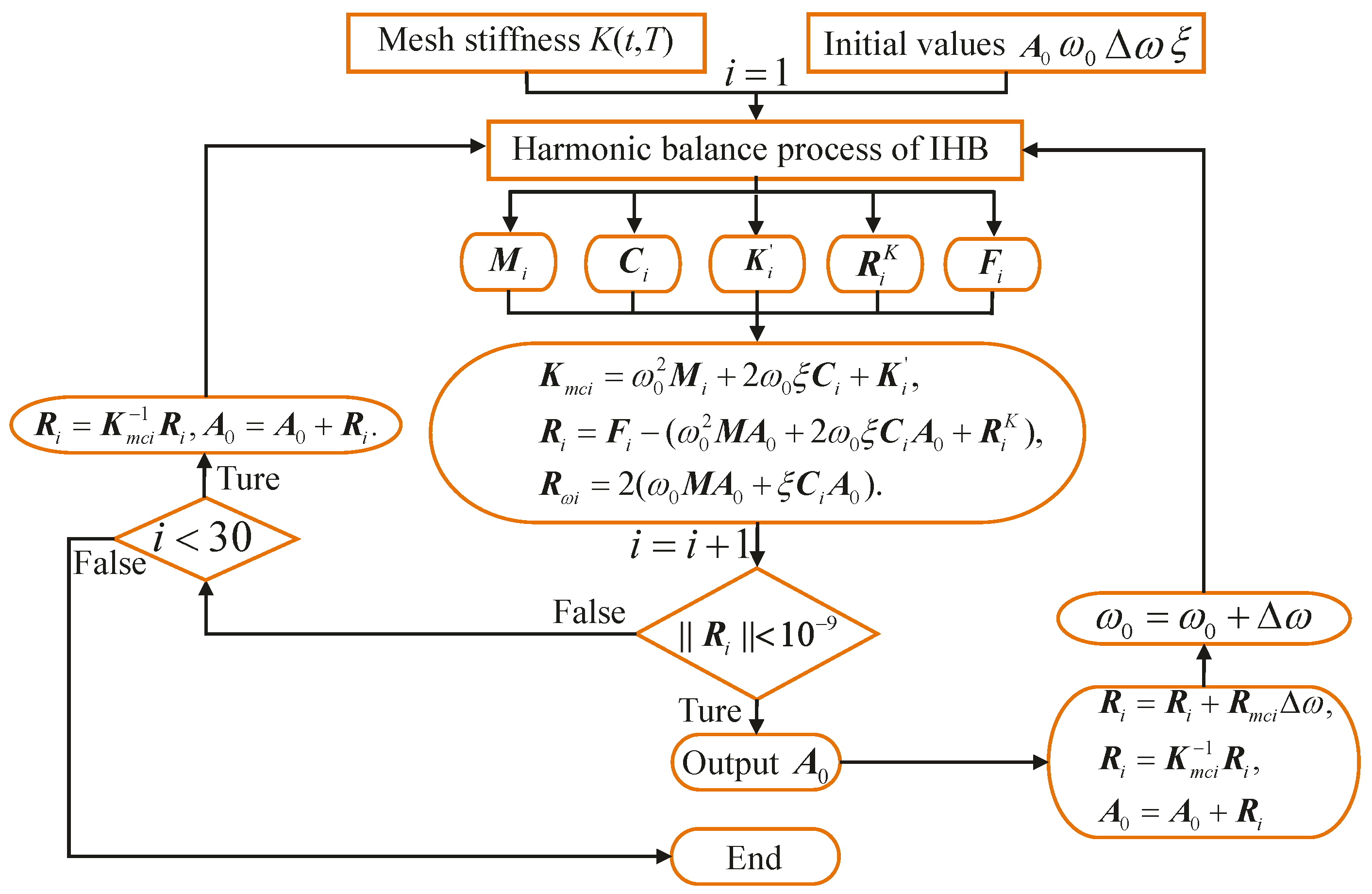
The solution process of Equation (28) begins with a guessed initial solution that need not be accurate. Frequency response curves can be traced point by point as long as the iterative procedure is repeated until the norm of is less than . In the increment process, three incremental methods containing the frequency increment, the amplitude increment, and the arc-length increment are employed to trace frequency response curves. In general, three incremental methods need to be used alternately. The computer program of the IHB method is written using Matlab 9.13, which can be downloaded using the site at https://ww2.mathworks.cn/ (accessed on 13 February 2025). A logic diagram of the IHB method is presented in Figure 2.
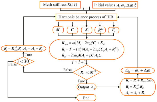
Figure 2.
A logic diagram the IHB method.
4. Analyzing of Stability and Bifurcation Analysis of Periodic Responses
The stability and bifurcation types of periodic responses of the gear transmission system considering time-varying mesh stiffness and a nonlinear displacement function are determined by employing the improved Floquet theory. After steady-state solutions of a nonlinear system are obtained by using the IHB method, the stability and bifurcation types of periodic solutions can be examined by adding a small perturbation on , as follows:
Substituting Equation (37) into Equation (17) and noting that satisfies Equation (17), the linearized equation, by taking as unknown, is obtained by neglecting high-order terms as follows:
Equation (38) is called the perturbed equation that perturbed from the equilibrium state [46]. The stability of steady-state periodic solutions depends on the stability of solutions of Equation (38), which is a linearized ordinary differential equation with a four-order Fourier series . The stability of the solutions of Equation (38) can be determined by applying the Floquet theory in the period . Let
Equation (38) can be described in state space form as
where
in which
Since is a periodic function of with the period = , is a periodic function with the same period as well.
For Equation (40), there exists a fundamental set of solutions as follows:
where , and is number of DOFs of the gear transmission system. This fundamental set can be described in matrix form as follows:
Equation (44) satisfies the matrix equation
where is a periodic function with the period ; i.e., , is a fundamental matrix solution. Hence, can be described by
where is an non-singular constant matrix that is called the transition matrix.
The Floquet theory states that the stability criteria of nonlinear systems depends on eigenvalues of the transition matrix . If all moduli of the eigenvalues of the transition matrix are less than 1, motions of nonlinear systems are bounded and the periodic solutions of the systems are stable; otherwise, the motions of nonlinear systems are unbounded and the periodic solutions of the systems are unstable. Key to determining the stability of nonlinear systems is to obtain the eigenvalues of the transition matrix by using an efficient and accurate method. Friedmann et al. [47] stated that the method for approximating the transition matrix developed by Hsu et al. [48] is the most efficient one. The proposed method divided the period into a number of equal parts, and the integration of the transition matrix over each equal part was performed. In this work, the period is divided into I equal parts denoted by , where . The magnitude of the i-th equal part is
where .
Define the step function S as
where denote values of the sign function in equal parts , respectively.
In the i-th equal part, the periodic coefficient matrix is replaced by the constant matrix as follows:
where
Finally, the transition matrix can be expressed as
where L is the number of retained terms in the Taylor expansion.
5. Numerical Results and Discussion
5.1. Verification of Analytical Model of Time-Varying Mesh Stiffness
The correctness of an analytical model of time-varying mesh stiffness is verified by performing comparisons between analytical results and FE results of time-varying mesh stiffness, and effects of loads on time-varying mesh stiffness are discussed.
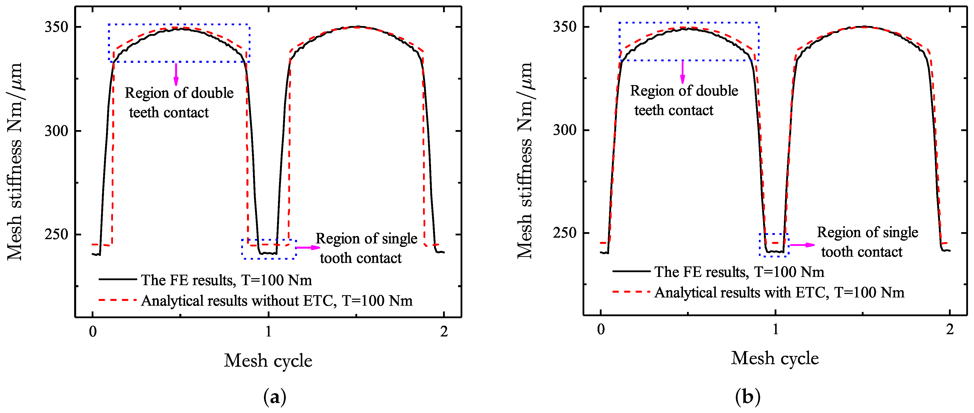
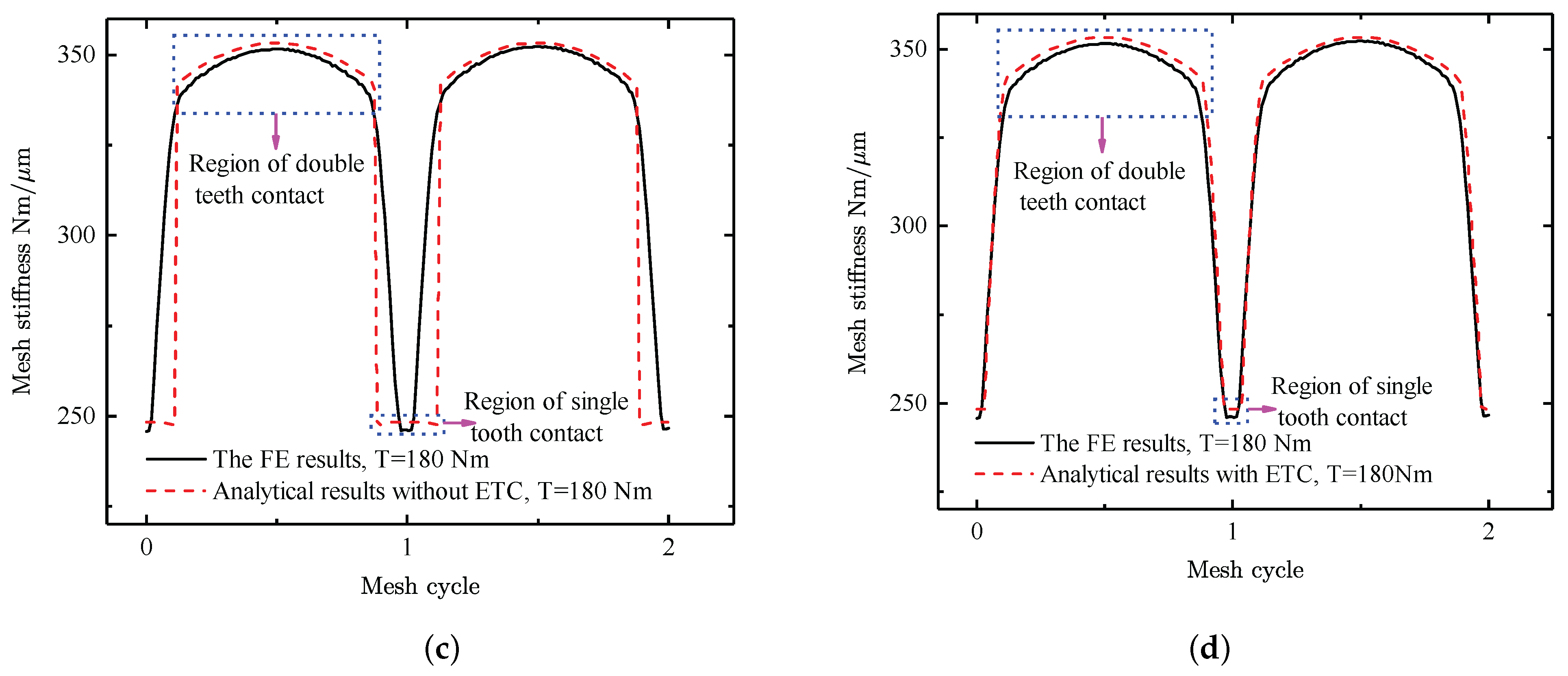
Comparisons between analytical results and FE results of time-varying mesh stiffness for loads of 100 Nm and 180 Nm are displayed in Figure 3, where dash lines represent analytical results and solid lines represent FE results. It can be seen that time-varying mesh stiffness from the analytical model developed in our previous work is a little larger than that obtained by the FE model.
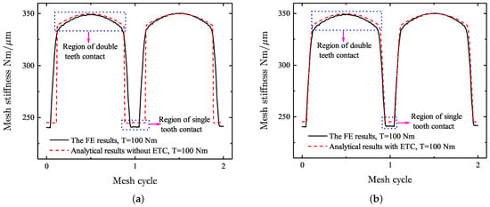
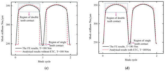
Figure 3.
Comparisons between analytical results and FE results of the time-varying mesh stiffness of the gear transmission system for loads of 100 Nm and 180 Nm: (a) the gear transmission system neglecting effects of the ETC for a load of 100 Nm, (b) the gear transmission system considering effects of the ETC for a load of 100 Nm, (c) the gear transmission system neglecting effects of the ETC for a load of 180 Nm, and (d) the gear transmission system considering effects of the ETC for a load of 180 Nm.
Figure 3a,c present comparisons between analytical results and FE results of time-varying mesh stiffness of the gear transmission system neglecting effects of the ETC for loads of 100 Nm and 180 Nm, respectively. It can be observed that curves of time-varying mesh stiffness from the analytical model coincide with those obtained by the FE model over a mesh period, regions of double teeth contact of time-varying mesh stiffness from the analytical model are smaller than those from the FE model, and regions of single tooth contact of time-varying mesh stiffness from the analytical model are larger than those from the FE model.
Figure 3b,d show comparisons between analytical results and FE results of time-varying mesh stiffness of the gear transmission system considering effects of the ETC for loads of 100 Nm and 180 Nm, respectively. It can be observed that curves of time-varying mesh stiffness from the analytical model agree very well with those obtained by the FE model over a mesh period. Thus, it can be concluded that the analytical model of time-varying mesh stiffness with effects of the ETC is effective, which can accurately express variations of time-varying mesh stiffness. Time-varying mesh stiffness of the gear transmission system can thus be accurately obtained using the proposed analytical model for any loads unless failures of teeth are generated.
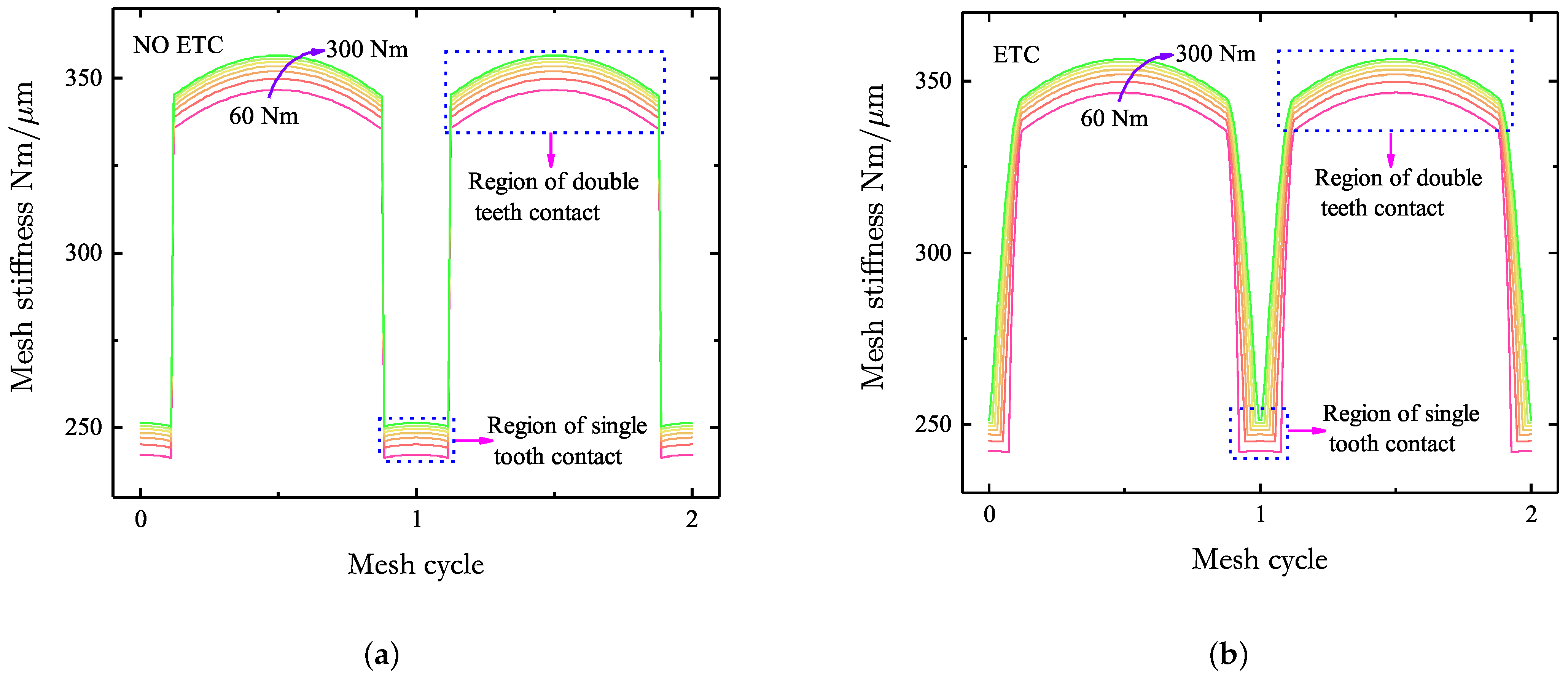
Curves of time-varying mesh stiffness under different loads are displayed in Figure 4. The increment amplitude between two loads is 40 Nm. It can be seen that time-varying mesh stiffness increases with the increase in loads, and when loads Nm, the incremental amplitude of time-varying mesh stiffness decreases with the increase in loads. Curves of time-varying mesh stiffness of the gear transmission system neglecting effects of the ETC under different loads are displayed in Figure 4a. It can be observed that regions of double teeth contact and regions of single tooth contact are invariant with the increase in loads. Curves of time-varying mesh stiffness of the gear transmission system considering effects of the ETC under different loads are shown in Figure 4b. It can be seen that region of double teeth contact increases with the increase in loads, and regions of single tooth contact decreases with the increase in loads. It can be concluded that the ETC has important influences on regions of double teeth contact and regions of single tooth contact of time-varying mesh stiffness, which can subsequently affect dynamic behaviors of the gear transmission system considering effects of the ETC.
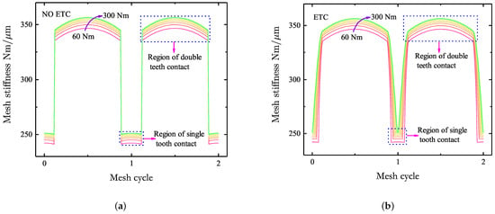
Figure 4.
Effects of loads on the time-varying mesh stiffness of the gear transmission system: (a) the gear transmission system neglecting effects of the ETC and (b) the gear transmission system considering effects of the ETC.
5.2. Verification of Dynamic Model and Analyzing of Nonlinear Phenomena of the Gear Transmission System
In this subsection, PR, SP-HR, nonlinear “softening-spring” characteristics, and bifurcations of the gear transmission system in consideration of time-varying mesh stiffness are discussed. The number of cosine terms is , and the number of sine terms is . Equation (21) can be written as
where
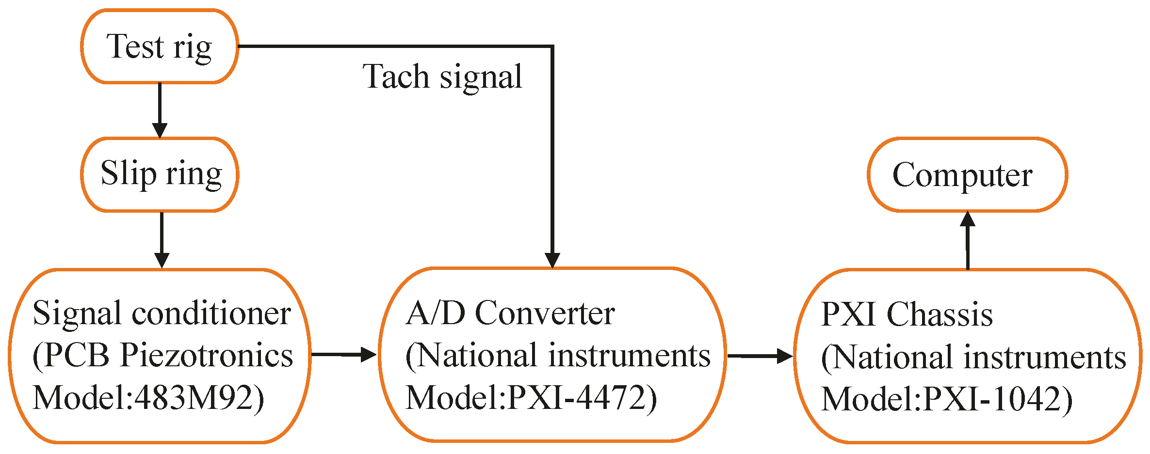
Results from the IHB method are verified in comparison with experimental results measured by Kahraman and Blankenship [49] based on a gear test rig. Experimental settings used in the process of collecting experimental data are presented as below: (a) a pair of spur test gears, (b) spherical roller bearings, (c) rigid split-line bearing pedestals, (d) test gear shafts, (e) reaction gear box, (f) compliant elastomer couplings, (g) flywheels, (h) a reaction gear set, (i) split hub couplings, (j) locking pins, (k) a 12 kW motor, (l) four miniature piezoelectric accelerometers, (m) slip rings, (n) optical encoders, (o) belt drive, and (p) polymer granite base. The sample size was set as a gear rotational speed range of 600 rpm to 4000 rpm with an increment of 50 rpm. A flowchart of collecting and analyzing experimental data is shown in Figure 5.
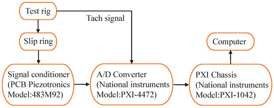
Figure 5.
Flowchart of collecting and analyzing experimental data.
In the published literature [49], the DTE was measured by attaching four miniature piezoelectric accelerometers tangentially to the pinion and the gear. An analog signal representing the DTE was processed by employing a programmable spectrum analyzer in real time. Frequency spectra of the DTE were obtained by performing the FFT, and the r-th mesh harmonic amplitude of the DTE were generated from the resulting frequency spectra. At last, an equivalent root-mean-square (rms) amplitude of an alternating component of the DTE is proposed to represent nonlinear responses of the gear transmission system, and can be expressed as
In order to obtain the equivalent root-mean-square (rms) amplitude of results from the IHB method to describe nonlinear responses of the gear transmission system, of results from the IHB method is obtained as follows:
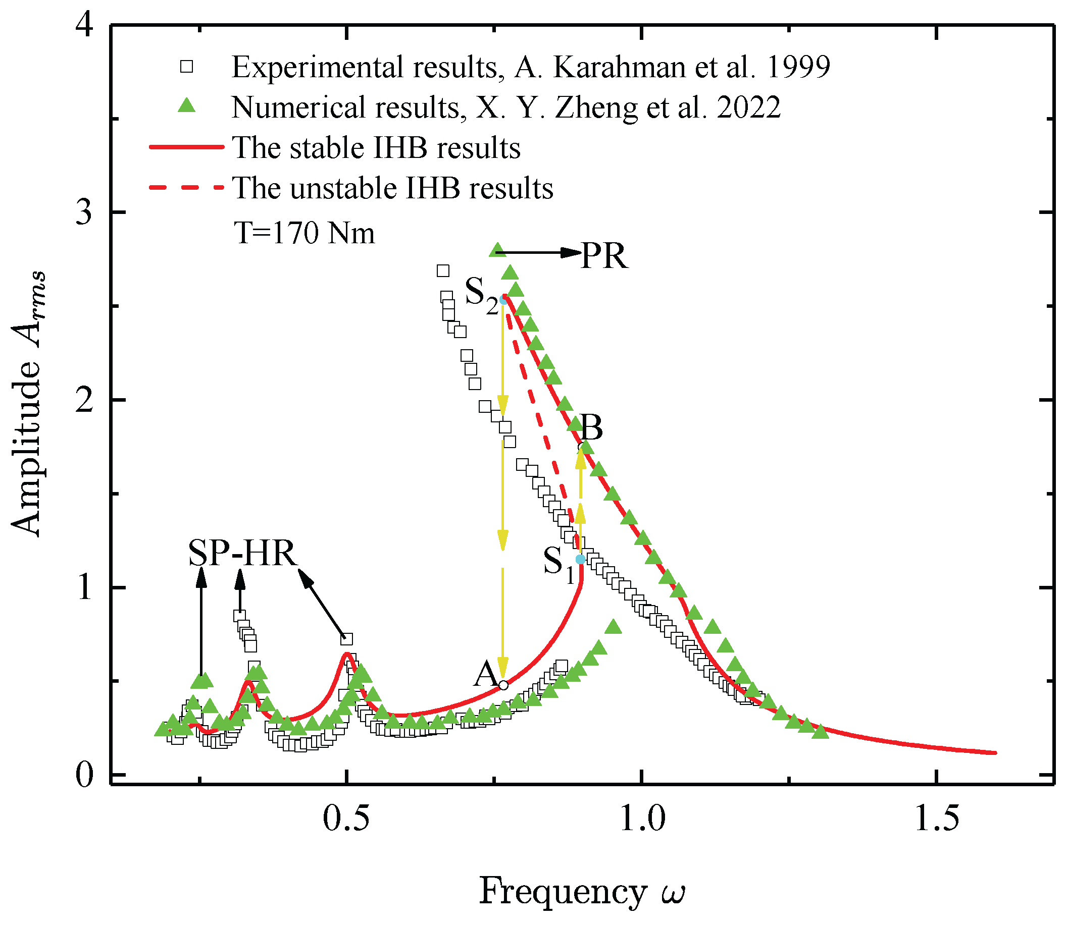
The amplitude of dynamic responses from experimental results [49] (represented by squares), numerical results [35] (represented by triangles), and the IHB method results (represented by line) are compared in Figure 6. In the process of calculating the IHB method results, time-varying mesh stiffness of the gear transmission system considering effects of the ETC for a load of 170 Nm is considered. It can be observed that the frequency response curve represented by the IHB method results exhibits similar trends as compared with those from experimental results and numerical results, and these frequency response curves display three SP-HR, one PR, and nonlinear “softening-spring” behaviors represented by frequency response curves bent to the left in PR regions, caused by separations of engaging teeth. Compared with frequency response curves from experimental results and numerical results, an unstable region between the point “” and the point “” is observed in the frequency response curve from the IHB method results. Bifurcations and the jump phenomenon of the frequency response curve represented by the IHB method results are displayed in Figure 6. It can be seen that there are two saddle-node bifurcation points (marked as “” and “”) in Figure 6. At saddle-node bifurcation points, periodic solutions become unstable and cause a jump phenomenon from a stable solution to another one, as evidenced by a real Floquet multiplier leaving the unit circle through the +1 direction along the real axis (Table 1). When sweeping the frequency from the left to the right, the stable periodic solution loses its stability at the saddle-node bifurcation point and jumps upward to the point B. When sweeping the frequency from the right to the left, the stable periodic solution becomes unstable at the saddle-node bifurcation point and jumps downward to the point A.
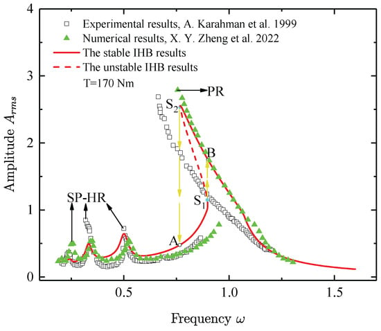
Figure 6.
Equivalent root-mean-square (rms) amplitude from experimental results [49], numerical results [35], and the IHB method results.

Table 1.
Floquet multipliers for different frequencies near bifurcation points “” and “” in the frequency response curve in Figure 6.
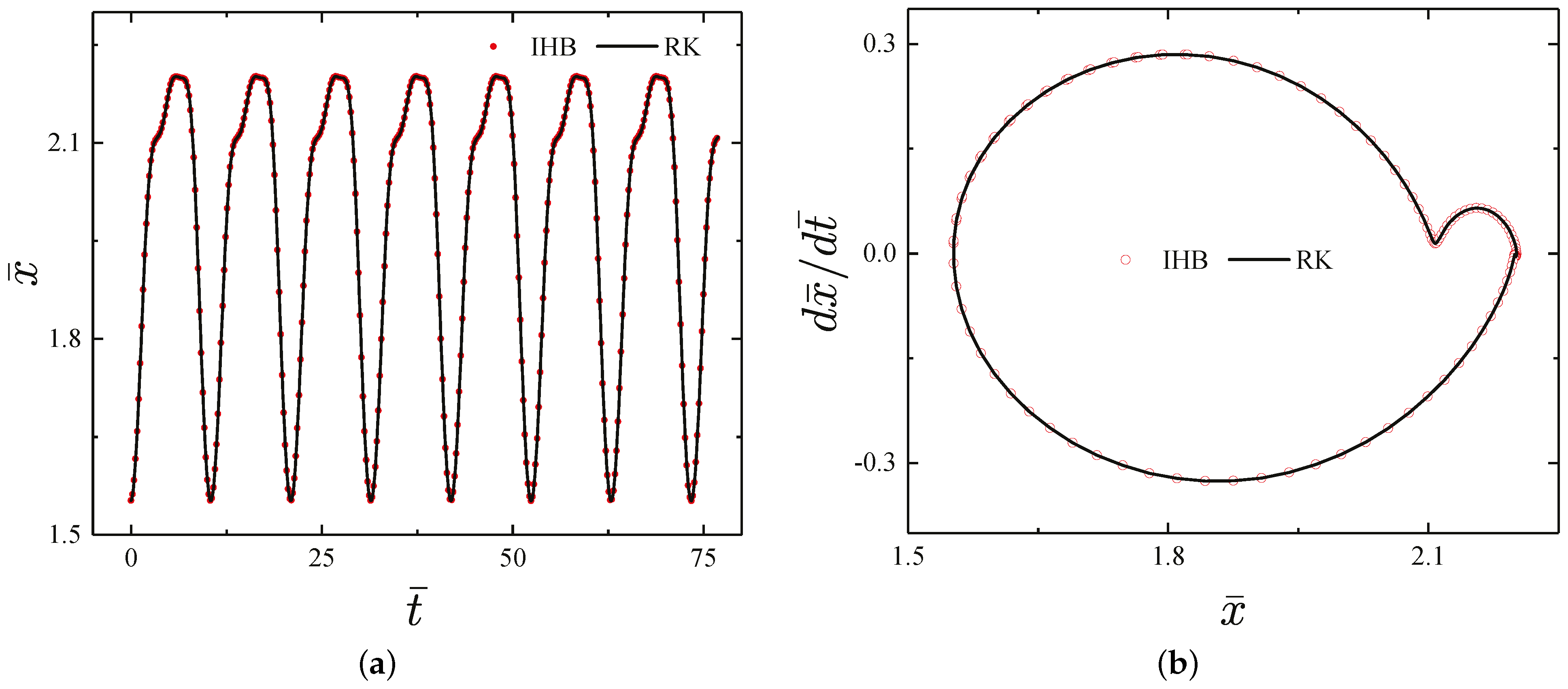
Figure 7 exhibits a time history map and a phase plane diagram of the periodic response from the IHB method results presented in Figure 6 when . The results obtained by the IHB method (represented by dots) match very well with that calculated by the fourth-order RK method (represented by a solid line) in Figure 7a, which indicate that the IHB method has sufficient accuracy to determine periodic responses of the gear transmission system in consideration of time-varying mesh stiffness and piecewise linearity. It can be seen that a phase plane diagram from the IHB method and the fourth-order RK method is one circle in Figure 7b, which indicate that the periodic response is period-1.
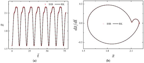
Figure 7.
Time history map and phase plane diagram of the periodic response when : (a) time history map and (b) phase plane diagram.
5.3. Effects of Loads on Nonlinear Dynamic Responses of the Gear Transmission System
In this work, time-varying mesh stiffness with effects of the ETC is considered. Effects of loads on nonlinear dynamic responses of the gear transmission system considering effects of the ETC and neglecting effects of the ETC are discussed in this subsection.
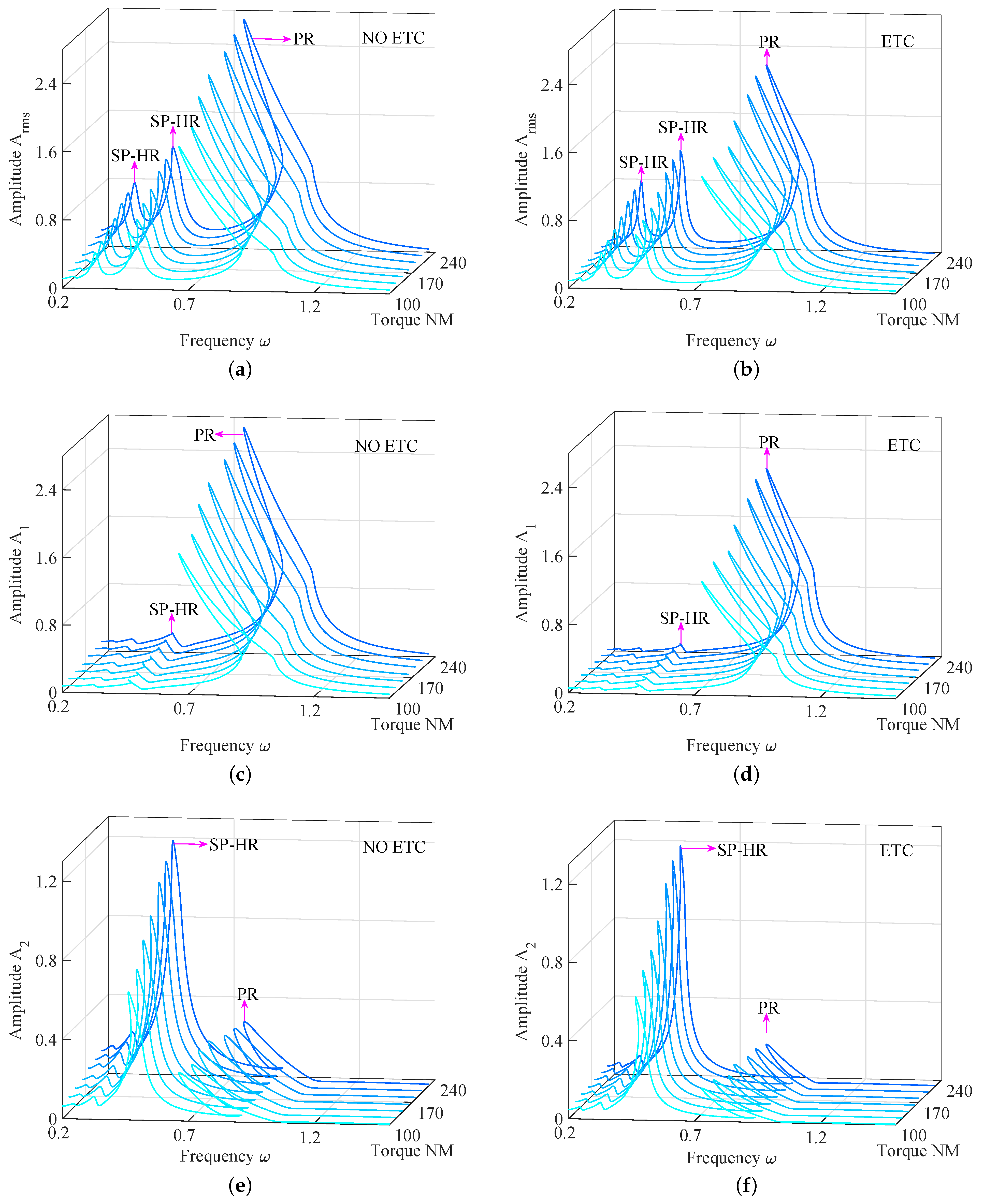
Figure 8 exhibits frequency response curves of the gear transmission system considering effects of the ETC and neglecting effects of the ETC under different loads, and it can be seen that amplitudes of frequency response curves of the gear transmission system increase with the increase in loads, and frequency response curves display nonlinear “softening-spring” behaviors, which caused by the separation between two engaging teeth. Additionally, it can be observed that nonlinear “softening-spring” behaviors represented by frequency response curves bent to the left gradually weaken with the increase in loads in Figure 8, which induced by the degree of separation between two engaging teeth decreases with the increase in loads. Under same loads, nonlinear “softening-spring” behaviors of frequency response curves of the gear transmission system considering effects of the ETC are more obvious than that of the system neglecting effects of the ETC, which caused by time-varying mesh stiffness of the system considering effects of the ETC, which is larger than that of the system neglecting effects of the ETC. Effects of loads on amplitudes of frequency response curves of the gear transmission system neglecting effects of the ETC are more obvious than that of loads on amplitudes of frequency response curves of the system considering effects of the ETC. Amplitudes of frequency response curves of the gear transmission system neglecting effects of the ETC are larger than that of frequency response curves of the system considering effects of the ETC.
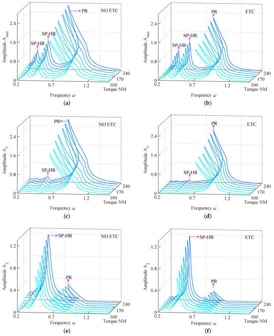
Figure 8.
Nonlinear dynamic responses of the gear transmission system under different loads: (a) the equivalent root-mean-square amplitude of the gear transmission system neglecting effects of the ETC and (b) the equivalent root-mean-square amplitude of the gear transmission system considering effects of the ETC; (c) the first-order harmonic amplitude of the gear transmission system neglecting effects of the ETC and (d) the first-order harmonic amplitude of the gear transmission system considering effects of the ETC; and (e) the second-order harmonic amplitude of the gear transmission system neglecting effects of the ETC and (f) the second-order harmonic amplitude of the gear transmission system considering effects of the ETC.
The frequency response curves of exist in two SP-HRs around and and one PR near in Figure 8a,b, and it can be seen that the frequency response curves display nonlinear “softening-spring” behaviors characterized by frequency response curves bent to the left at PR and SP-HR around , which caused by the separation of engaging teeth. Additionally, amplitudes at PR are larger than that at SP-HR of the frequency response curves.
In Figure 8c,d, the frequency response curves of exhibit obvious PR phenomena. SP-HR phenomena in the frequency response curves of are not obvious, and amplitudes at PR are larger than that at SP-HR of the frequency response curves. The reason is that PR phenomena are mainly dominated by the first-order harmonic amplitude. Additionally, the frequency response curves show obvious nonlinear “softening-spring” behaviors at PR.
In Figure 8e,f, the frequency response curves of display SP-HR phenomena around and PR phenomena near . Amplitudes at SP-HR around are very small. Amplitudes at SP-HR around are obviously larger than that at PR near in the frequency response curves. The reason is that SP-HR phenomena around in the frequency response curves are primarily dominated by the second-order harmonic amplitude. Additionally, the frequency response curves show nonlinear “softening-spring” behaviors at SP-HR around and PR near .
5.4. Effects of Loads on Bifurcation Characteristics of Frequency Response Curves
Besides effects of loads on amplitudes, resonance phenomena, and nonlinear “softening-spring” behaviors of frequency response curves, loads can also influence bifurcation characteristics of frequency response curves. Effects of loads on bifurcation characteristics of frequency response curves are investigated in detail in this subsection.
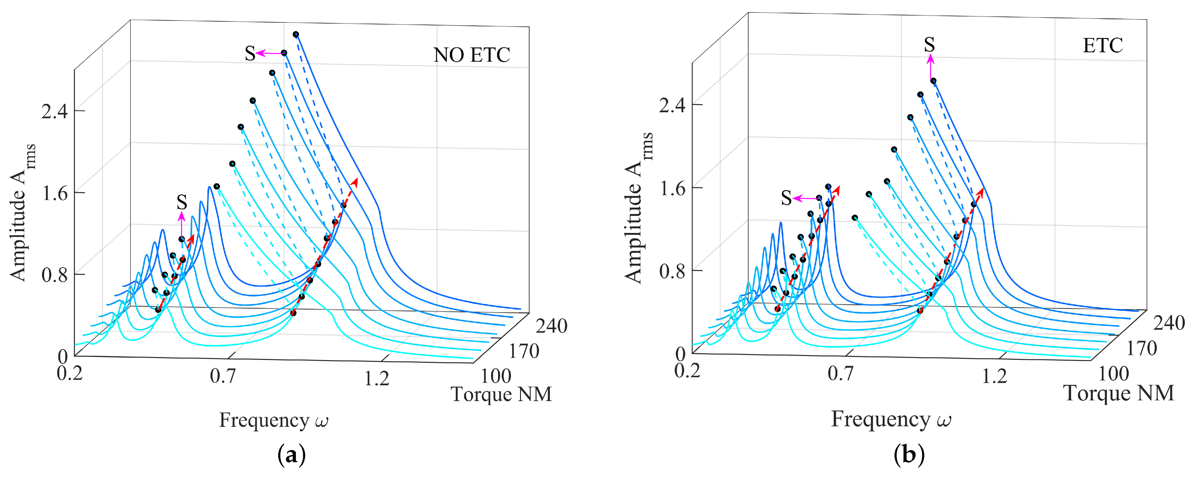
The unstable phenomena and bifurcation behaviors of period responses of the gear transmission system considering time-varying mesh stiffness are exhibited in Figure 9. Solid lines and dash lines denote stable period responses and unstable period responses, respectively, in Figure 9, and saddle-node bifurcation points in frequency response curves are denoted by black points that are marked as “S”. One can see that there exist some saddle-node bifurcation points at regions of PR and regions of SP-HR in Figure 9, and frequency response curves generate jump phenomena from one stable period solution to another one at saddle-node bifurcation points, and saddle-node bifurcation points move upward in the vertical direction with increasing loads, which lead to unstable regions in frequency response curves decreasing with increasing loads (marked by red arrows).
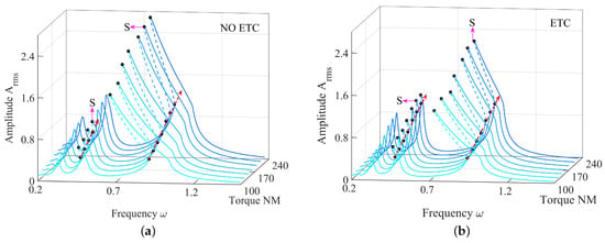
Figure 9.
Effects of loads on the bifurcation characteristics of the gear transmission system: (a) bifurcation characteristics of the gear transmission system neglecting the effects of the ETC and (b) bifurcation characteristics of the gear transmission system considering the effects of the ETC.
Frequency response curves of the gear transmission system neglecting effects of the ETC under different loads are shown in Figure 9a. It can be observed that unstable regions of frequency response curves at SP-HR and PR gradually decrease with the increase in loads, and saddle-node bifurcation points of frequency response curves at SP-HR gradually disappear with the increase in loads. Frequency response curves of the gear transmission system considering effects of the ETC under different loads are exhibited in Figure 9b. It can be seen that the decrease in unstable regions at SP-HR and PR of frequency response curves with the increase in loads is not discovered, and the disappearance of saddle-node bifurcation points at SP-HR and PR of frequency response curves with the increase in loads is not observed.
6. Conclusions
Nonlinear dynamic responses of a single-DOF model of the gear transmission system considering time-varying mesh stiffness are investigated in detail in this work. An analytical model of time-varying mesh stiffness with effects of the ETC is developed, and the correctness of the analytical model is demonstrated in comparison with results from the FE method. Governing equations of the single-DOF model of the gear transmission system are proposed by using the Newton’s second law, and the effectiveness of the single-DOF model is verified as compared with experimental results. The IHB method is improved to determine periodic responses of the single-DOF model of the gear transmission system. The Floquet theory combined with piecewise linearity is extended to analyze the stability and bifurcation characteristics of periodic responses. Results from the IHB method are in agreement with those obtained by numerical integration, which is verified by a time history diagram and a phase plane map.
Effects of loads on time-varying mesh stiffness are discussed, and it can be concluded that time-varying mesh stiffness increases with the increase in loads. Periodic responses of the single-DOF model of the gear transmission system considering time-varying mesh stiffness are analyzed in detail. In the periodic responses of the single-DOF model of the gear transmission system, nonlinear “softening-spring” behaviors characterized by frequency response curves bent to the left, jump phenomena from one stable periodic solution to another one, saddle-node bifurcation, PR, and SP-HR are observed. Effects of loads on the periodic responses of the single-DOF model of the gear transmission system are discussed, amplitudes of frequency response curves increase with the increase in loads, and nonlinear “softening-spring” behaviors of frequency response curves gradually weaken with the increase in loads. Unstable regions of frequency response curves of the gear transmission system neglecting effects of the ETC gradually decrease with the increase in loads, and saddle-node bifurcation points of frequency response curves of the gear transmission system considering effects of the ETC gradually disappear with the increase in loads. Additionally, this work provides a theoretical foundation to analyze nonlinear behaviors of gear transmission systems.
Author Contributions
Conceptualization, J.H. and W.Z.; Methodology, J.H.; Software, F.L.; Formal analysis, F.L. and X.Z.; Data curation, F.L.; Writing—original draft, F.L.; Writing—review & editing, J.H. and W.Z.; Supervision, J.H.; Project administration, J.H.; Funding acquisition, J.H. and W.Z. All authors have read and agreed to the published version of the manuscript.
Funding
Financial support from the National Natural Science Foundation of China (Grant No. 12372028), the National Science Foundation (Grant No. 2329791), and the Guangdong Basic and Applied Basic Research Foundation (Grant No. 2022A1515011809) is gratefully acknowledged.
Data Availability Statement
The authors attest that all data for this study are included in the paper.
Conflicts of Interest
There are no conflicts of interest.
Appendix A. The Detailed Formulation Process of the Matrix K j′ and the Vector R jK
The detailed formulation process of the matrix and the vector is presented as follows:
where
and
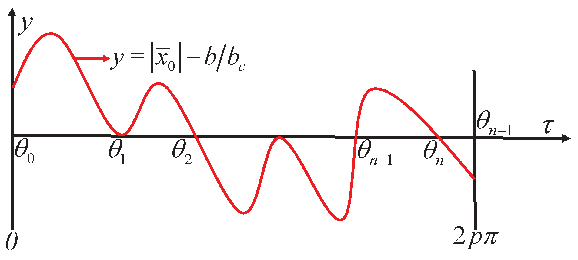
in which n denotes the number of zeros of the equation within the interval ; represent zeros of the equation , as presented in Figure A1; , ; and and are step functions that depend on the sign functions and , respectively, and can be described as
respectively. Here, , and and denote the values of sign functions and in the subintervals , respectively. It should be noted that in the process of calculating Equations (A3)–(A5), the values of and should be 1 and 0 [50], respectively.
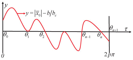
Figure A1.
Zeros of the equation .
Figure A1.
Zeros of the equation .
References
- Lin, T.J.; Ou, H.G.; Li, R.F. A finite element method for 3D static and dynamic contact/impact analysis of gear drives. Comput. Methods Appl. Mech. Eng. 2007, 196, 1716–1728. [Google Scholar] [CrossRef]
- Eritenel, T.; Parker, R.G. An investigation of tooth mesh nonlinearity and partial contact loss in gear pairs using a lumped-parameter model. Mech. Mach. Theory 2012, 56, 28–51. [Google Scholar] [CrossRef]
- Fang, Y.N.; Liang, X.H.; Zuo, M.J. Effects of friction and stochastic load on transient characteristics of a spur gear pair. Nonlinear Dyn. 2018, 93, 599–609. [Google Scholar] [CrossRef]
- Raghuwanshi, N.K.; Parey, A. Mesh stiffness measurement of cracked spur gear by photoelasticity technique. Measurement 2015, 73, 439–452. [Google Scholar] [CrossRef]
- Yogesh, P.; Parey, A. Crack behavior in a high contact ratio spur gear tooth and its effect on mesh stiffness. Eng. Fail. Anal. 2013, 34, 69–78. [Google Scholar]
- Wang, J.D.; Howard, I. Finite element analysis of high contact ratio spur gears in mesh. J. Tribol. 2005, 127, 469–483. [Google Scholar] [CrossRef]
- Zhan, J.X.; Fard, M.; Jazar, R. A CAD-FEM-QSA integration technique for determining the time-varying meshing stiffness of gear pairs. Measurement 2017, 100, 139–149. [Google Scholar] [CrossRef]
- Liang, X.H.; Zhang, H.S.; Zuo, M.J.; Qin, Y. Three new models for evaluation of standard involute spur gear mesh stiffness. Mech. Syst. Signal Process. 2018, 101, 424–434. [Google Scholar] [CrossRef]
- Yang, D.C.H.; Lin, J.Y. Hertzian damping, tooth friction and bending elasticity in gear impact dynamics. J. Mech. Transm. Autom. Des. 1987, 109, 189–196. [Google Scholar] [CrossRef]
- Liang, X.H.; Zuo, M.J.; Pandey, M. Analytically evaluating the influence of crack on the mesh stiffness of a planetary gear set. Mech. Mach. Theory 2014, 76, 20–38. [Google Scholar] [CrossRef]
- Meng, Z.; Shi, G.X.; Wang, F.L. Vibration response and fault characteristics analysis of gear based on time-varying mesh stiffness. Mech. Mach. Theory 2020, 148, 103786. [Google Scholar] [CrossRef]
- Liu, X.Z. Vibration modelling and fault evolution symptom analysis of a planetary gear train for sun gear wear status assessment. Mech. Syst. Signal Process. 2022, 166, 108403. [Google Scholar] [CrossRef]
- Liu, H.; Zhang, C.; Xiang, C.L.; Wang, C. Tooth profile modification based on lateral-torsional-rocking coupled nonlinear dynamic model of gear system. Mech. Mach. Theory 2016, 105, 606–619. [Google Scholar] [CrossRef]
- Meng, F.S.; Xia, H.; Zhang, X.; Wang, J.; Jin, Y. Study on nonlinear dynamic characteristics of gear system with 3D anisotropic rough tooth surface based on fractal theory. Int. J. Non-Linear Mech. 2023, 150, 104366. [Google Scholar] [CrossRef]
- Tian, H.X.; Zhao, X.J.; Huang, W.K.; Ma, H. A stiffness model for EHL contact on smooth/rough surfaces and its application in mesh stiffness calculation of the planetary gear set. Tribol. Int. 2024, 196, 109720. [Google Scholar] [CrossRef]
- Zhou, W.G.; Zhu, R.P.; Li, Z.W.; Liu, W.; Wang, J. An improved dynamic model of spur gears considering delayed meshing out of the contact point due to root crack. Mech. Syst. Signal Process. 2024, 212, 111325. [Google Scholar] [CrossRef]
- Zhang, T.; Lin, T.J.; Fu, L.Y. Analytical and experimental study on acoustic-vibration characteristics of double-helical planetary gear transmission systems with multi-field coupling effect. Mech. Syst. Signal Process. 2025, 224, 112143. [Google Scholar] [CrossRef]
- Zheng, X.Y.; Luo, W.J.; Hu, Y.M.; He, Z.; Wang, S. Study on the mesh stiffness and nonlinear dynamics accounting for centrifugal effect of high-speed spur gears. Mech. Mach. Theory 2022, 170, 104686. [Google Scholar] [CrossRef]
- Ma, H.; Zeng, J.; Feng, R.J.; Pang, X.; Wen, B. An improved analytical method for mesh stiffness calculation of spur gears with tip relief. Mech. Mach. Theory 2016, 98, 64–80. [Google Scholar] [CrossRef]
- Ma, H.; Pang, X.; Feng, R.J.; Zeng, J.; Wen, B. Improved time-varying mesh stiffness model of cracked spur gears. Eng. Fail. Anal. 2015, 55, 271–287. [Google Scholar] [CrossRef]
- Jiang, Y.; Zhu, H.; Li, Z.; Peng, Z. The nonlinear dynamics response of cracked gear system in a coal cutter taking environmental multi-frequency excitation forces into consideration. Nonlinear Dyn. 2016, 84, 203–222. [Google Scholar] [CrossRef]
- Wan, Z.G.; Cao, H.R.; Zi, Y.Y.; He, W.; He, Z. An improved time-varying mesh stiffness algorithm and dynamic modeling of gear-rotor system with tooth root crack. Eng. Fail. Anal. 2014, 42, 157–177. [Google Scholar] [CrossRef]
- Liu, G.; Parker, R.G. Dynamic modeling and analysis of tooth profile modification for multimesh gear vibration. J. Mech. Des. 2008, 130, 1121402. [Google Scholar] [CrossRef]
- Pan, W.J.; Li, X.P.; Wang, L.L. Nonlinear response analysis of gear-shaft-bearing system considering tooth contact temperature and random excitations. Appl. Math. Model. 2019, 68, 113–136. [Google Scholar] [CrossRef]
- Moradi, H.; Salarieh, H. Analysis of nonlinear oscillations in spur gear pairs with approximated modelling of backlash nonlinearity. Mech. Mach. Theory 2012, 51, 14–316. [Google Scholar] [CrossRef]
- Mo, S.; Zhang, Y.X.; Song, Y.L. Nonlinear vibration and primary resonance analysis of non-orthogonal face gear-rotor-bearing system. Nonlinear Dyn. 2022, 108, 3367–3389. [Google Scholar]
- Bruzzone, F.; Rosso, C. Comparison of two possible dynamic models for gear dynamic analysis. In Topics in Modal Analysis & Parameter Identification, Proceedings of the 41st IMAC, A Conference and Exposition on Structural Dynamics; Conference Proceedings of the Society for Experimental Mechanics Series; Springer: Cham, Switzerland, 2023; Volume 9, pp. 183–192. [Google Scholar]
- Bruzzone, F.; Rosso, C.; Theodossiades, S. Dynamic reduction technique for nonlinear analysis of spur gear pairs. Nonlinear Dyn. 2024, 112, 15797–15811. [Google Scholar] [CrossRef]
- Bruzzone, F.; Maggi, T.; Marcellini, C.; Rosso, C. Gear teeth deflection model for spur gears: Proposal of a 3D nonlinear and non-hertzian approach. Machines 2021, 9, 223. [Google Scholar] [CrossRef]
- Oliveri, L.; Rosso, C.; Zucca, S. Influence of actual static transmission error and contact ratio on gear engagement dynamics. In Nonlinear Dynamics, Proceedings of the 35th IMAC, A Conference and Exposition on Structural Dynamics; Conference Proceedings of the Society for Experimental Mechanics Series; Springer: Cham, Switzerland, 2017; Volume 1, pp. 143–154. [Google Scholar]
- Al-Shyyab, A.; Kahraman, A. Non-linear dynamic analysis of a multi-mesh gear train using multi-term harmonic balance method: Sub-harmonic motions. J. Sound Vib. 2005, 279, 417–451. [Google Scholar] [CrossRef]
- Hou, J.Y.; Yang, S.P.; Li, Q.; Liu, Y. Analysis of dynamic characteristics of a fractional-order spur gear pair with internal and external excitations. J. Comput. Nonlinear Dyn. 2022, 17, 021004. [Google Scholar] [CrossRef]
- Yang, Y.; Xia, W.; Han, J.; Song, Y.; Wang, J.; Dai, Y. Vibration analysis for tooth crack detection in a spur gear system with clearance nonlinearity. Int. J. Mech. Sci. 2019, 157, 648–661. [Google Scholar] [CrossRef]
- Liu, G.H.; Hong, J.; Parker, R.G. Influence of simultaneous time-varying bearing and tooth mesh stiffness fluctuations on spur gear pair vibration. Nonlinear Dyn. 2019, 97, 1403–1424. [Google Scholar] [CrossRef]
- Zheng, X.Y.; Hu, Y.M.; He, Z.; Xiao, Y.; Zhang, X. On the extended tooth contact and nonlinear dynamics for spur gears—An analytical model. Mech. Mach. Theory 2022, 175, 104958. [Google Scholar] [CrossRef]
- Kahraman, A.; Singh, R. Non-linear dynamics of a geared rotor-bearing system with multiple clearances. J. Sound Vib. 1991, 144, 469–506. [Google Scholar] [CrossRef]
- Lau, S.L.; Zhang, W.S. Nonlinear vibrations of piecewise-linear systems by incremental harmonic balance method. J. Appl. Mech. 1992, 59, 153–160. [Google Scholar] [CrossRef]
- Choi, Y.S.; Noah, S.T. Forced periodic vibration of unsymmetric piecewise-linear systems. J. Sound Vib. 1988, 121, 117–126. [Google Scholar] [CrossRef]
- Zhou, S.H.; Song, G.Q.; Li, Y.M.; Huang, Z.; Ren, Z. Dynamic and steady analysis of a 2-DOF vehicle system by modified incremental harmonic balance method. Nonlinear Dyn. 2019, 98, 75–94. [Google Scholar] [CrossRef]
- Vorotnikov, K.; Starosvetsky, Y. Bifurcation structure of the special class of nonstationary regimes emerging in the 2D inertially coupled, unit-cell model: Analytical study. J. Sound Vib. 2016, 377, 226–242. [Google Scholar] [CrossRef]
- Huang, J.L.; Zhang, B.X.; Zhu, W.D. Quasi-periodic solutions of a damped nonlinear quasi-periodic mathieu equation by the incremental harmonic balance method with two time scales. J. Appl. Mech. 2022, 89, 091009. [Google Scholar] [CrossRef]
- Liao, F.L.; Huang, J.L.; Zhu, W.D. Nonlinear Vibration of a Multi-Degree-of-Freedom Gear Transmission System With Multipiecewise Linear Functions. J. Comput. Nonlinear Dyn. 2023, 18, 041003. [Google Scholar] [CrossRef]
- Huang, J.L.; Wang, T.; Zhu, W.D. An incremental harmonic balance method with two time-scales for quasi-periodic responses of a Van der Pol–Mathieu equation. Int. J. Non-Linear Mech. 2021, 135, 103767. [Google Scholar] [CrossRef]
- Ju, R.; Fan, W.; Zhu, W.D. Comparison between the incremental harmonic balance method and alternating frequency/time-domain method. J. Vib. Acoust. 2021, 143, 024501. [Google Scholar] [CrossRef]
- Huang, J.L.; Su, K.L.R.; Lee, Y.Y.R.; Chen, S. Various bifurcation phenomena in a nonlinear curved beam subjected to base harmonic excitation. Int. J. Bifurc. Chaos 2018, 28, 1830023. [Google Scholar] [CrossRef]
- Huang, J.L.; Su, K.L.R.; Chen, S.H. Precise Hsu’s method for analyzing the stability of periodic solutions of multi-degrees-of-freedom systems with cubic nonlinearity. Comput. Struct. 2009, 87, 1624–1630. [Google Scholar] [CrossRef]
- Friedmann, P.; Hammond, C.E.; Woo, T.H. Efficient numerical treatment of periodic systems with application to stability problems. Int. J. Numer. Methods Eng. 1977, 11, 1117–1136. [Google Scholar] [CrossRef]
- Hsu, C.S.; Cheng, W.H. Applications of the theory of impulsive parametric excitation and new treatments of general parametric excitation problems. J. Appl. Mech. 1973, 40, 78–86. [Google Scholar] [CrossRef]
- Kahraman, A.; Blankenship, G.W. Effect of involute contact ratio on spur gear dynamics. J. Mech. Des. 1999, 121, 112–118. [Google Scholar] [CrossRef]
- Shen, Y.J.; Yang, S.P.; Liu, X.D. Nonlinear dynamics of a spur gear pair with time-varying stiffness and backlash based on incremental harmonic balance method. Int. J. Mech. Sci. 2006, 48, 1256–1263. [Google Scholar] [CrossRef]
Disclaimer/Publisher’s Note: The statements, opinions and data contained in all publications are solely those of the individual author(s) and contributor(s) and not of MDPI and/or the editor(s). MDPI and/or the editor(s) disclaim responsibility for any injury to people or property resulting from any ideas, methods, instructions or products referred to in the content. |
© 2025 by the authors. Licensee MDPI, Basel, Switzerland. This article is an open access article distributed under the terms and conditions of the Creative Commons Attribution (CC BY) license (https://creativecommons.org/licenses/by/4.0/).

