Article

The Space Phasors Theory and the Conditions for the Correct Decoupling of Multiphase Machines

by
Luis Serrano-Iribarnegaray
1,* and
Jorge Bonet-Jara
2
1
Departamento de Ingeniería Eléctrica, Universitat Politècnica de València, C/Camino de Vera s/n, 46022 València, Spain
2
Instituto de Tecnología Eléctrica, Universitat Politècnica de València, C/Camino de Vera s/n, 46022 València, Spain
*
Author to whom correspondence should be addressed.
Machines 2025, 13(2), 107; https://doi.org/10.3390/machines13020107
Submission received: 21 November 2024 / Revised: 15 January 2025 / Accepted: 24 January 2025 / Published: 29 January 2025
(This article belongs to the Section Electrical Machines and Drives)

Abstract

:
This paper first analyzes the general statements accepted in the technical literature concerning the complete dynamic decoupling of constant air-gap multiphase machines with space harmonics (usually resorting to the instantaneous symmetrical components, ISCs) and shows that they are not correct, since they only hold (and only with good approximation) for the particular case of converter-controlled machines. It then deduces in a rigorous theoretical way the correct conditions in all cases for both a precise and an approximate decoupling of multiphase machines and thereupon verifies them through numerous simulations. To do that, the Space Phasors Theory (SPhTh) is applied, whose true core, often unknown or misunderstood, is clearly explained. Preceding this point, the concept of the dynamic phasor of g sequence, which is a fundamental tool in the SPhTh, is introduced, and a necessary historical and critical review of the ISCs is undertaken.

1. Introduction

The physical meaning and history of the instantaneous symmetrical components (ISCs) in their application to the analysis of electrical machine transients have been detailed in [1], which together with [2], is the base of this work. As indicated there, the theory of symmetrical components (SCs) originated with Fortescue, who published it in a paper [3] which, including the discussion, is 113 pages long, with more than 300 formulae. Although Fortescue pointed out that his formulae could be applied to electrical quantities of arbitrary time variation, he only applied them in [3] to the analysis of many practical industrial cases of rotating machines in the asymmetrical steady state.
In 1954, Lyon published his book [4] on analyzing transients in three-phase machines, using as an essential tool the SCs formulae in [3], but this was applied to the instantaneous values of the electrical quantities (an application field of the SCs unexplored until then, but mathematically correct, as Fortescue had already pointed out). Thus, the instantaneous symmetrical components (ISCs) for three-phase machines were “rediscovered” for the electrical engineering world in their most powerful version and presented as excellent, but they were mere analytic tools for the study of transients. Their use within this context led Lyon to no longer call them a decomposition but rather a transformation. (For the sake of completeness, it is interesting to add that mathematicians already knew of the ISCs in the 18th and 19th centuries under the name of ‘trigonometric interpolation polynomials’. A detailed exposition is in the valuable, although highly mathematical, paper [5], where its author wrote (page 356) that electrical engineers seem to be unaware that the ISCs method is an old method, known in mathematics as trigonometric interpolation’) Three years later, Hochrainer, in his book [6], introduced for the German-speaking area the ISCs and also presented them as a mathematical transformation without any underlying physical meaning ([6], p. 279). Later on, White and Woodson extended the transform to multiphase machines considering no saturation and only the case of the sinusoidal distribution of the air-gap induction ([7], pp. 546 and 569).
The ISCs of currents (analogously for voltages and flux linkages) of an m-phase symmetrical winding are as follows ([7]):
i 0 ¯ i 1 ¯ i 2 ¯ i m 1 ¯ = 1 m 1 1 1 1 1 1 a 1 a 2 a m 1 1 a 2 a 2 2 a 2     ( m 1 ) 1 1 a ( m 1 ) a ( m 1 ) 2 a ( m 1 ) ( m 1 ) i 1 ( t ) i 2 ( t ) i 3 ( t ) i m ( t )
where i1(t), i2(t)…im(t) are each of the currents that circulate in each of the phases of the multiphase machine and a = e j γ   with   γ = 2 π / m . From (1), the expression for the general ISCs, i k ¯ , (with k = 0, 1, 2…m − 1) is as follows:
i k ¯ = 1 m       x   =   1 m i x ( t )   e j   ( x 1 )     k   γ
It is apparent that the ISCs i 1 ¯ ,   i 2 ¯   etc .   and   i m 1 ¯ ,   i m 2 ¯ etc. in (1) are conjugate complex quantities. In spite of that, when analyzing in [4] the three-phase machines, a pair of conjugate complex equations systematically appears, although one of these equations is simply superfluous. This fact was rightly criticized in the long paper [8], whose title, which takes the form of a question, clearly anticipated the debate contained therein and underlined the remarkable advantages of the method proposed one year earlier in [9].
In their book [9], Kovacs and Racz (who also assume the hypothesis of no space harmonics), instead of starting from abstract mathematical transformations, analyzed first in all detail ([9], pp. 61–67), from a physical perspective, the dynamic m.m.f. space wave produced by a three-phase winding and deduced its expression, which has a direct correlation with the time phase currents. In addition to its formula and its physical meaning, they characterized this space wave by a graphical tool they called “current space vector”, I (in German: Stromraumvektor). Later on, as they could not find space quantities related to the phase flux linkage and voltage time quantities, they introduced very briefly and only mathematically, by a mere formal analogy to I, the so-called voltage (U) and flux linkage (Ψ) “space vectors” ([9], p. 75). Yet, although there was no physical meaning for them in terms of space waves, the authors in [9] profusely used them together with I in a graphical manner to explain the three-phase machine equations. This new graphical viewpoint of approaching and illustrating the transients, in contrast to the abstract matrix transformation perspective, provided a much better insight into the phenomena, in addition to the reduction in the number of equations. As to this last point, notice that, mathematically, the “space vectors” I, U, and Ψ in [9] are the first ISCs of the machine currents, voltages, and flux linkages, which are sufficient (no need for the second ISCs, as discussed in [8]), to characterize the three-phase machine dynamic equations, provided there are no homopolar components.
On the other hand, many years earlier, following a quite different approach, Park had introduced [10] his complex quantities for the sole purpose of simplifying the dynamic three-phase machine equations. And as it turned out that the expression of the “space vectors” in [9] coincided with their homologous complex quantities in [10], Park’s complex quantities were then renamed in quite a few cases as “Park vectors”, although it was not uncommon to ignore the process and the physical reality behind this change in name.
In any case, it should be noted that in the discussion to [10], Kron already indicated in passing that Park’s current complex quantity could be considered as a “current linear density wave” ([10], p. 354]). However, in his later highly abstract publications, Kron does not seem to have been interested in defining or searching for similar correlations between other (if at all existing) machine space waves and Park’s voltage and flux linkage complex quantities.
So far, with the exception of [7], all of the above references [4,6,7,8,9,10] refer to ISCs or to “space vectors” (a conceptually incorrect name, since they are not vectors as understood in physics but complex quantities that symbolize space waves) in three-phase machines. In [11], Stepina stated that any of the current ISCs in a multiphase machine with space harmonics were associated with a specific group of m.m.f. (or of current linear density) space waves. He gave their mathematical relationship and, as a practical and useful example, he detailed the groups of current sheet space waves corresponding to each one of the current ISCs in m-phase windings ranging from m = 2 to 7 ([11], Table 1, p. 392).
Stepina’s contribution was a very valuable contribution in that it linked space waves (“space vectors”) and the ISCs of the currents in the very general case of multiphase machines, including their current sheet harmonic waves. Nevertheless, as to the ISCs of Ψ and U, it continued to be impossible to make any physical sense of them, even in the simplest case introduced in [9] of three-phase machines without space harmonics. Yet, just these two “space vectors” are by far the two most important ones, and understanding and deducing their relationships to both, their machine space waves and the time values of the corresponding phase quantities in the general case (multiphase machines with spaces harmonics), are essential for understanding how the machine actually works and how to “untangle” its intricate structure. This “untangling” is precisely the base for the decoupling of the multiphase machine, as shown in this paper.
This paper is organized as follows: Section 2 analyzes the general statements accepted in the literature as to the complete dynamic decoupling of constant air-gap multiphase machines with space harmonics, shows their starting inconsistency, and rejects them. The decoupling problem and its correct answer are addressed in Section 6 and Section 7 by means of the SPhTh. Before this, it is necessary to become familiar with the suitable analytical tools and the true core of the SPhTh, often unknown or clearly misunderstood. This previous task is carried out in Section 3, Section 4 and Section 5. Section 3 introduces the concepts of the dynamical m-phase system (DmPhS) of the g sequence and its dynamic time phasor. Through that, Kapp’s time phasor concept is extended from steady to transient states, whereby the new notion of a “g” sequence of a phasor must be introduced. The next section determines the formulae of all of the dynamic time phasors necessary to characterize the corresponding electrical quantity of a symmetrical multiphase system in the most general case (this, moreover, gives a first physical interpretation of the ISCs). Section 5 shows in a precise way the true core of the Space Phasor Theory (SPhTh). It defines first the Ψ and U space phasors as symbolical representations of the two most important machine internal (space waves) quantities and calculates thereafter their correlation with their homologous time phase quantities. Relying directly on the results of Section 3, Section 4 and Section 5, Section 6 shows how to “untangle” the intricate structure of the multiphase machine and decompose it into several simpler and independent machines. This section also gives a second and deeper physical interpretation of the ISCs. Finally, Section 7, which is by far the longest one, discusses theoretically and establishes thereafter the conditions in all cases for both a precise and an approximate machine decoupling, which is then confirmed by numerous simulations.
This paper also includes an appendix, entitled “On the Space Phasors Theory and its relationship to the Park, Clarke and Instantaneous Symmetrical Component Transformations” (Appendix A). It is specially intended for users of the mentioned transformations who wish to connect and compare them with the SPhTh.

2. On the Incorrect Statements as to the Method to Obtain Complete Dynamic Decoupling of Multiphase Machines with Space Harmonics in the General Case

The authors totally agree with the statement ([12], p. 492) that “Probably, the most comprehensive treatment of the modelling procedure (for multiphase machines) at a general level is available in [7]”.
In chapter 10 (“General Analysis of the n–m Winding Machine”) of the above book [7], resorting to the ISCs and assuming that phase windings are “cosinusoidally distributed in space on a smooth magnetic structure and that the mutual flux density between rotor and stator produced by them is a sinusoidal function of space” (p. 569), its authors, after a rigorous mathematical process, conclude that “Therefore, the only quantities which must be considered to determine electromechanical energy conversion properties are the positive- and negative-sequence currents of an equivalent two-phase machine…Since all the other (n + m − 4) symmetrical component volt-ampere equations except the + − components for stator and rotor are linear and non-torque producing, it follows that the symmetrical component transformation reduces the n − m machine to an equivalent two-phase energy converter plus a set of independent networks (n + m − 4) in number” (pages 588 and 590).
The above conclusions, formulated in a very descriptive, clear, and precise way, are usually expressed in today’s literature in an equivalent but more abstract and mathematical language. To put it simply, leaving aside the homopolar components, in the m-phase machine there are (m − 1)/2 so-called mutually orthogonal bidimensional subspaces (m odd), of which only one is involved in the torque generation. Alternatively, there are (m − 1)/2 pairs of current and voltage components. Only one of them (α-β components) produces torque, with each one of the remaining non-torque producing pairs (x-y components) completely decoupled from all the others.
Relying on these conclusions, deduced and only valid under the assumptions very clearly and precisely indicated in [7], a very audacious and qualitative leap was made; namely, it was stated that one can use the additional x-y components of the machine to increase the torque density by utilizing its harmonic fields, with the dynamic torque produced by each xy component independent from all the others ([12], p. 495; [13], p. 637; [14], p. 1896). The stator and rotor phase number may be different, which is usual in most squirrel-cage motors.
It would be unfair and a sign of ignorance not to recognize the important contribution of this idea in developing multiphase machines for useful and practical applications.
Yet, this idea or statement, which is about twenty years old, has been accepted worldwide in the technical literature, but, surprisingly, it has never been mathematically proven. This, on the other hand, could hardly have been achieved, simply because it lacks a correct theoretical base.
Indeed, the statement above requires that there are air-gap harmonic fields. Yet, at the same time, the results and formulae in [7], on which it fully relies, apply and have been deduced only for machines without harmonic fields (sinusoidal air-gap induction). This clear contradiction alone openly questions the general validity of the claim.
This problem of the machine decoupling in the general case and its correct answer are addressed in Section 6 and Section 7 by means of the SPhTh. Before performing it, it is imperative and unavoidable to first be familiar with the contents in Section 3, Section 4 and Section 5.

3. Definition of a Dynamic m-Phase System of g Sequence—Extending the Concept of Kapp’s Time Phasor to Dynamic States of m-Phase Systems

In the steady state of single-phase alternating current circuits, sinusoidal quantities are very often involved. As is well known (Figure 1), their instantaneous values may be determined by the projection on a Cartesian axis of a “rotating vector” (Kapp’s time phasor) with constant amplitude and speed [15]. Let us first extend Kapp’s phasor concept to transient states and symmetrical m-phase systems.
By definition, the m quantities (m currents, m voltages, etc.) of an m-phase symmetrical winding are said to constitute a dynamic m-phase system (DmPhS) of “g” sequence if they meet the following equations (γ = 2π/m):
x 1 ( t ) = x ( t )   cos   [   ε ( t ) g 0 γ ] x 2 ( t ) = x ( t )   cos     ε ( t ) g 1 γ ...................................................................... x m ( t ) = x ( t )   cos     ε ( t ) g ( m 1 ) γ
where x(t) and ε(t) can be arbitrary time functions. Their physical and geometrical interpretation is given two paragraphs below. For g = mq + 1, mq + 2, mq + 3, etc., where q is any positive natural number, the values in (3) are the same as for g = 1, 2, 3, etc., respectively. For g = mq or zero, the system is called the homopolar DmPhS.
A DmPhS of “g” sequence only has two independent variables, x(t) and ε(t). Thus, it can be fully characterized by a new mathematical tool (a complex time quantity) called in [2] the “dynamic time phasor of a DmPhS of “g” sequence”:
X g , [ m ] = x ( t )     e j   ε ( t )   g , [ m ]  
Variables x(t) and ε(t) determine the amplitude and position in the complex plane of the dynamic time phasor. Let us first consider a DmPhS with g = 1. It is apparent from (3) and (4) that in this case, the quantity of any phase is obtained by simply projecting the phasor onto the phase axis.
Now let us fictitiously exchange the phase positions in a cyclic manner according to the g-value, that is, to go from phase y to the next phase y + 1, one has to traverse the angle gγ, instead of γ (see Figure 2). Keeping this in mind, it is clear that in a DmPhS of g sequence, the quantity of any phase with its axis placed at its actual position, y, is obtained by simply projecting the phasor onto the axis that would belong to this phase after having performed with g sequence the cyclic exchange of phases. Mathematically ( e stands for “real part of”):
x y ( t ) = e   X     e j   g   ( y 1 ) γ
The sum of currents, voltages, etc., of several DmPhSs, S1, S2, etc., of the same sequence, g, produces a DmPhS which also has the g sequence. The dynamic time phasor of the resultant DmPhS equals the vectorial sum of the dynamic time phasors associated with S1, S2, etc. Notice that although functions x(t) and ε(t) in (3) may be arbitrary and very different for the different systems S1, S2, etc., the statement above on the vectorial sum of dynamic time phasors always holds.
The g and (m − g) sequences are called complementary sequences. Any DmPhS of g sequence can be converted ([1], p. 336) into a DmPhS of (m − g) sequence according to the formula (* stands for conjugate complex):
X   g , [ m ] = X *     m   g , [ m ]
These formulae show that DmPhSs with equal or complementary sequences can be added up, and the result can be characterized by just one dynamic time phasor.
The dynamic time phasors can be regarded as a powerful extension of Kapp’s steady state time phasors. They can be dealt with mathematically (complex time-varying quantities) and graphically (vectorial addition), just as with Kapp’s classical phasors.
With regard to this point, notice that any DmPhS of g sequence is the result of projecting with g sequence into the system phases a phasor whose amplitude and speed may vary in an arbitrary manner. In contrast, Kapp’s phasor turns with constant amplitude and speed (see Figure 1). The DmPhS is fully characterized by the phasor. This fact provides, when operating with transients, a powerful tool, both for their mathematical as well as their graphical and visual analysis.
Notice finally that the classical sinusoidal three-phase system is as follows:
x 1 ( t ) = X cos ω t + η x 2 ( t ) = X cos ω t + η 2 π 3 x 3 ( t ) = X cos ω t + η 2 2 π 3
where this belongs to the most simple family of DmPhSs, characterized by g = 1 and a phasor that turns at constant speed with constant amplitude. In accordance with (4), such a three-phase system is defined by the following expression:
X 1 , 3 = X e j ε ( t ) 1 , 3 = X e j ( ω t + η ) 1 , 3

4. Dynamic Time Phasors of Symmetrical Multiphase Systems with Arbitrary Currents

Since the essential features of dynamic time and space phasors can be best illustrated with m-phase systems with an odd number of phases, in this paper, m will always be assumed odd. The phase 1 axis always coincides with the real axis.
Let it be a three-phase symmetrical winding with three arbitrary currents (or voltages, flux linkages, etc.) without homopolar components, i1(t), i2(t), and i3(t). It must be possible to obtain these currents through the projection of a dynamic time phasor onto the phase axes, that is (γ = 2π/m):
i 1 ( t ) = e   I A ;           i 2 ( t ) = e   I A   e j   γ ;       i 3 ( t ) = e   I A   e j   2   γ
Indeed, since the sum of the phase currents is zero, there are only two independent variables and equations in (9), which just determine magnitude and angle of IA. After a simple calculation, there is the following:
I A = i A ( t )   e j   ε ( t ) = 2 3 i 1 ( t ) + i 2 ( t )   e j   γ + i 3 ( t )   e j   2   γ
Let it be now a five-phase winding with arbitrary currents, but again without homopolar components. Since there are four independent currents, it seems at first sight that the two following independent phasors:
I A = i A ( t )   e j   ε A ( t )   ;                 I B = i B ( t )   e j   ε B ( t )
suffice to determine the current of any phase (sum of the two phasor projections onto the phase). Yet, this way, all the currents would actually be derived from the projections of one only effective phasor (sum of IA and IB). Therefore, and for the purpose of specifying the phase currents, it is necessary to impose the additional condition that IA and IB also differ from one another as to the way in which their projections on the winding phases take place. This could be achieved in many ways. The most direct one is to imagine that the phase positions are exchanged in a cyclic manner, depending on the phasor considered, e.g., for phasor IA, the phases are placed in their actual sequence, 1, 2, 3, 4, 5 (that is, g = 1), whereas for IB, they are assumed to be in the sequence 1, 4, 2, 5, 3 (that is, g = 2). Again, after a rather simple calculation, there is the following (more details in [1], p. 337, and [2]):
I A = i A ( t )   e j   ε A ( t ) = 2 5       x   =   1 5 i x ( t )   e   j     ( x 1 )     γ             I B = i B ( t )   e j   ε B   ( t ) = 2 5       x =   1 5 i x ( t )   e   j     ( x 1 )     2     γ
Notice that, according to the developments in the previous section, IA and IB are, simply, the dynamic current phasors of sequence 1 and 2 of the five-phase winding. In other words, through the phasors of sequence 1 and 2, the original five arbitrary currents system without homopolar components has been decomposed into two independent systems, with each of them characterized by one only dynamic time phasor. Obviously, only dynamic phasors of the same sequence can be vectorially combined and added up.
This process can be easily generalized to symmetrical windings with an arbitrary number of phases, m, and without homopolar components. In that case, (m − 1)/2 phasors of sequence g = 1, 2…(m − 1)/2 are needed. The formula for the general dynamic time phasor of g sequence is given by the following (details in [1,2]):
I g , [ m ] = 2 m       x   =   1 m i x ( t )   e j   ( x 1 )     g   γ
As seen in a previous section, the dynamic currents (or voltages, flux linkages, etc.) in all of the phases of a symmetrical m-phase winding can be characterized by just one dynamic time phasor if, and only if, these phase currents constitute a DmPhS of g sequence. Yet, even in the most general case of arbitrary currents, the set of the phase currents can always be characterized by (m − 1)/2 dynamic time phasors of sequences g = 1, 2 … (m − 1)/2 plus, if necessary, a homopolar dynamic time phasor. In other words, the overall system can always be decoupled, in the most general case, into a homopolar system and (m − 1)/2 completely independent DmPhSs, each of which is defined by its dynamic time phasor, whose formula is given in (13).
Except for factor 2, Formula (13) coincides with (2) of the ISCs. Thus, the ISCs have a first important physical meaning: they are the set of dynamic time phasors that decouple and fully describe, mathematically and graphically, the time evolution, in the most general case, of the phase quantities in an m-phase symmetrical winding.

5. The Hard Core of the Space Phasors Theory and the Essential Ψ and U Space Phasors

The approach overwhelmingly used today for machines transient analysis is the magnetic coupling circuit approach (MCCA), which regards the machine as a network made up of resistances and inductances, many of which vary with the rotor position. This network is dealt with by means of abstract and complex matrix transformations.
By contrast to the MCCA, the SPhTh introduced in [2] states that a machine can also be regarded as an electromechanical device that produces electromagnetic (field) waves with a restricted propagation capacity, namely they are forced to turn inside its air-gap. These space waves should have the following properties:
  • Be the most important and dominant ones.
  • Be characterized by dynamic space phasors.
  • Be easily correlated with their corresponding machine time phase quantities.
These requirements are fully met by the space waves of the magnetic vector potential, A, and of the scalar electric potential difference, φ.
Thus, the SPhTh in [2] completely rejects space phasors to be mere mathematical entities without physical meaning (an idea always found for phasors Ψ and U in papers on three-phase machines, let alone in the case of multiphase machines). Its starting point is just the opposite: space phasors are always to be introduced representing fundamental and clearly defined machine internal (space) quantities.
As to these quantities, the extraordinary importance of A and φ was already strongly stressed by the Nobel laureate Feynman, who wrote “the vector potential A (together with the scalar electric potential, φ that goes with it) appears to give the most direct description of the physics.” ([16], page 15–14). The key role played by A and φ in electromagnetics can also be seen very clearly in this, in our opinion, excellent and extraordinary book [17].
To put into practice in our case Feynman’s fundamental idea, let it be a long (negligible end effects) salient pole machine with axial conductors at the cylindrical stator surface. From Maxwell’s equation,
B = r o t ( A )
it follows that the total flux linkages of an arbitrary stator single turn, “ab” (Figure 3), of any stator phase is given by the following:
Ψ ab ( t ) = S B · d S =   S r o t ( A ) · d S =   A · d l = ( A z a A z b )   ·   l =   l y   =   a , b ±   A z , y
That is, Ψab is the sum of the vector potential values, Az, at the positions of the two turn conductors, multiplied by the machine length, l (notice that A and B are constant in the axial direction, z, since, as usual, the magnetic field distribution in the machine is assumed to be bidimensional). Thus, the flux linkages of the whole phase are simply the algebraic sum of the A values at their conductor positions.
Notice that (15) always holds, no matter the rotor shape or whether the magnetic circuit be saturated or not. Thus, if the magnetic vector potential space wave at the stator surface is known, the phase flux linkages are obtained immediately from this space wave in the most general case.
Analogously, if the space wave of the stator electric potential difference in axial direction, φz, is known (potential difference between the two ends of an axial straight conductor), the total voltage of any stator phase K is obtained by simply adding up the electric potential difference values at all of the conductor positions:
u K ( t ) = y = a , b , c , d ±   φ z , y
Dynamic space phasors are excellent tools to operate with the space waves in (15) and (16). By definition, a space phasor is an oriented segment in the complex plane that symbolically represents the spatial sinusoidal distribution of an internal machine quantity. The phasor always points to the positive maximum of the wave (case of bipolar waves), and its modulus is equal to the wave amplitude. Both the wave amplitude and speed may vary arbitrarily.
Usually, the internal quantity is not sinusoidal. Then, a harmonic space phasor is assigned to each space harmonic of its Fourier expansion. To this end, a domain transformation is defined in such a manner that any angle, α, in the machine domain becomes an angle να (ν = absolute harmonic order) in its corresponding phasorial domain. Notice that through this transformation (which boils down to transforming the mechanical angles into electrical ones), any multipolar wave is characterized by one only space phasor (the same coordinate in the phasorial domain corresponds to all its positive crests in the machine (see Figure 4)).
Let it be a sinusoidal wave with ν = hp pole pairs distributed over the stator cylindrical surface of a salient pole machine (an induction wave, a wave of electric potential difference, etc.). If xhp(t) is the instantaneous amplitude of the space wave and ε(t) defines any of its instantaneous positive crests in the machine, the wave expression becomes
x h p ( α , t ) = x h p ( t ) cos h p ε ( t ) α )
On the other hand, this space wave of hp pole pairs, as just stated, is fully characterized in its phasorial domain by its space phasor, whose expression in the most general case is as follows:
X h p   = x h p ( t )   e j h p   ε ( t )  
From (17) and (18), it follows immediately that
x h p ( α , t ) = e   X h p         e j h p α
That is, the stator quantity (e.g., induction, electric potential difference, etc.) at an axial straight line of the stator surface specified in the machine domain by the angular coordinate α is given by the projection of its space phasor on the straight line defined by hpα in the phasorial domain (see Figure 5).
Thus, according to (19), the voltage of one conductor produced by the electric potential difference wave (the “voltage wave”) with hp pole pairs is equal to the projection in the phasorial domain of its voltage space phasor onto the conductor. Therefore, the voltage of any stator phase of an m-phase symmetrical winding due exclusively to this voltage wave is given by the sum of each one of the projections of its voltage space phasor, Uhp, onto the phase conductors. This sum turns out to be equal to the projection of the phasor Uhp onto the phase axis multiplied by h, where Z is the number of phase conductors connected in series and ξh is the winding factor for the harmonic of relative order h. Finally, the total voltage in (16) of any of the m-winding phases is easily obtained through the sum of the projections of all of the voltage phasors onto the phase axis, multiplying each projection by its corresponding h.
The analogous process of sums of projections holds for the Ψ phasors and their associated phase flux linkages.

6. Untangling the Intricate Structure of the Multiphase Machine

All of the sums in the previous section (a rather simple calculation) have been carried out in [2]. The main results are as follows (see, among other formulae, the mathematical deduction, implications, and interpretation of Equation (23) in [2]): let it be, e.g., a seven-phase symmetrical winding with p pole pairs placed at the stator of a salient pole machine. Each of the voltage waves (that is, electric potential difference space waves in axial direction) with p, 8p, 15p, etc., pole pairs (in other words, each of the harmonic waves of relative order h = 7q + 1 with q = 0, 1, 2, 3, etc.) only produce in the phases of the 7-phase winding a voltage DmPhS of g = 1. Likewise, each of the waves of order h = 7q + 2; h = 7q + 3, etc., produce in the phases a voltage DmPhS of g = 2, 3, etc., respectively.
Therefore, for a seven-phase winding, all of the electric potential difference waves can be classified into seven independent families. The instantaneous amplitudes and positions of the different waves belonging to the same family are, in the general case, quite different from one another. However, all of them originate DmPhSs of the same sequence, and therefore, as explained in Section 3 and Section 4, can be added up to give a resultant DmPhS of this same sequence. Thus, the combined action of all of the waves of a family on the voltages of the winding phases can be characterized by just one effective voltage space phasor of the family. Or alternatively, the resultant voltage DmPhS in the polyphase winding produced by a whole family of waves can be imagined to be produced by one only effective voltage space wave, the phasor of which is just the effective space phasor of the family of waves.
Moreover, the two voltage DmPhSs produced by the families with h = 7q ± 1 are DmPhSs of complementary sequence. Hence, they can be added up so that just one space phasor suffices to characterize the combined action of this group of two families. The same statement applies to the families with h = 7q ± 2 and h = 7q ± 3. Thus, the combined effect of all of the electric potential difference waves on the voltages of the seven phases in any dynamic state is fully characterized by just three effective voltage space phasors (plus one homopolar phasor, if necessary). These conclusions apply too to the magnetic vector potential space waves (space phasors Ψ) and can be extended to a symmetrical winding with an arbitrary number of phases [2]. It should be underlined that these groups of U and Ψ space waves, mathematically established in [2] for the first time, coincide with the groups determined by Stepina for the I space waves following a quite different path, which can only be applied to the currents [11].
In summary, the phase voltages of an m-phase symmetrical winding placed on a cylindrical stator or rotor are completely defined by the projections, in their phasorial domains, of the (m − 1)/2 stator or rotor effective voltage space phasors (plus a homopolar phasor, if necessary) on the axes of these phases. This also applies to the flux linkages and currents, no matter how arbitrary their time variations may be. Yet, this is exactly the same as with the (m − 1)/2 dynamic time phasors calculated in Section 4. Thus, mathematically, the expressions of the effective space phasors must coincide with that of the dynamic time phasors in Section 4, which, in turn, coincide with the formulae of the ISCs multiplied by two. This, in addition, gives a deeper physical meaning of the ISCs: they symbolize the current linear density, the electric potential difference, and the magnetic vector potential space waves in the m-phase machine (more details in [1]).
If we apply a current to a phase placed on a cylindrical stator or rotor and we know the spatial distribution of its conductors, we can determine any space harmonic (and its space phasor) of the current sheet wave produced by the phase. This is not the case with the voltage space wave. Indeed, if we know the phase current, we know the current in each one of its conductors (which makes it much simpler to cope with I than with U waves), whereas in the case of an applied voltage, we do not know the individual conductor voltages, only their sum. This is the reason why only the effective voltage space phasors of an m-phase winding can be determined from layout and voltages of its phases. On the contrary, under similar circumstances, we can calculate not only the effective current space phasors but also the individual space phasors of all of the space harmonics of the current sheet produced by the m-phase winding. Moreover, once these formulae ([2], p. 87) are calculated, it is easy to prove ([2], p. 92) that if the currents applied to an m-phase winding constitute a DmPhS of g sequence, then all the current sheet space waves produced by them are, exclusively, of relative order h = qm ± g.
It is now convenient to summarize (more details in [2]) the main results that apply to constant air-gap multiphase machines (either permanent magnet synchronous machines PMSM, induction IM, or doubly fed asynchronous machines DFAM) with m-phases in the stator and rotor and without homopolar components (always to be avoided):
(a)
For a three-phase machine, there is only one space phasor U in the stator (all of the corresponding harmonic space waves belong to the same group, h = 3q ± 1 with h odd) and one in the rotor. The same applies to the Ψ and I effective space phasors. These two (U,Ψ, I) triads fully describe the machine behavior.
(b)
Each of the (m − 1)/2 U space phasors in the stator (or rotor) characterize an effective voltage space wave in the stator (or rotor). More precisely, they synthesize through an equivalent wave the contribution to the voltages of the stator (or rotor) phases due to a specific group of electric potential difference space waves existing in the stator (or in rotor). Analogous considerations apply to the Ψ and I space phasors.
(c)
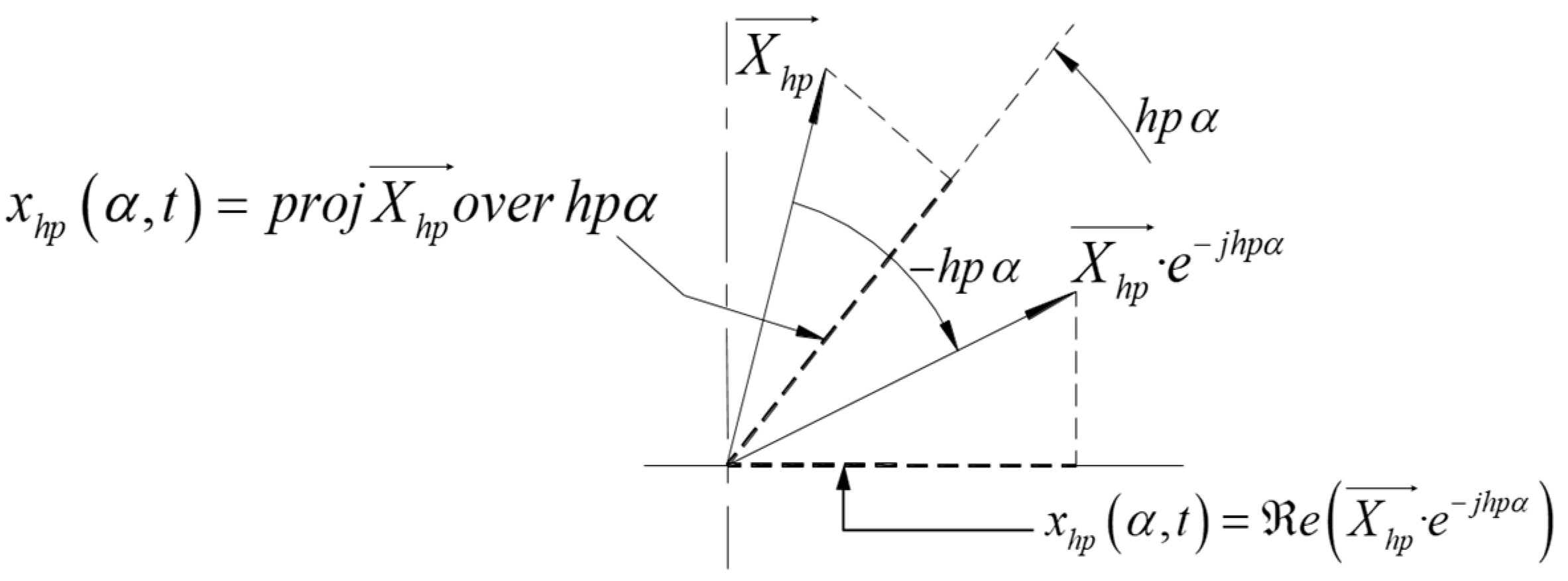
The mentioned total contribution to a phase of any of the wave groups is obtained through a very simple procedure: by projecting its effective space phasor onto the phase axis.
(d)
Each one of the independent groups of space waves in stator, together with its homologous group in rotor, can be associated with a fictitious machine which, therefore, has one only set of phasors (U,Ψ,I) in the stator and one in the rotor, just as in three-phase machines.
In summary, each one of the different triads (U,Ψ, I) of effective dynamic space phasors in the multiphase machine is related to one specific and independent group of space harmonics. This physical reality, analyzed in detail in [2], constitutes the base that enables to “untangle” the intricate structure of a constant air-gap symmetrical multiphase machine and to split it into a equivalent set of (m − 1)/2 fictitious machines, mechanically coupled but electrically independent.
A possibility that is usually the first that comes to mind to describe any one of these fictitious machines is that of a machine whose winding factors are all zero, except for those corresponding to the harmonics belonging to the wave group associated with the machine (e.g., ξ h = 0 h m q ± g ). There is also a second and more interesting possibility: indeed, in the most general case, an m-phase induction machine (IM) without homopolar components can be fed by a voltage system, for the definition of which (m − 1)/2 DmPhSs (or (m − 1)/2 dynamic time phasors) are required. Within this context, each of the fictitious and mechanically coupled machines can be considered to be equal to the actual machine but imposing the condition that it is fed by only one of these DmPhSs of voltages. Obviously, both pictures or approaches lead to the same set of air-gap space harmonics, which are equivalent and can be easily implemented in a program.
It should be pointed out that the authors in [18] dealt with the simpler case (neither phases number nor windings in the rotor) of PMSM. Following a completely different approach, they arrived for the mentioned particular case of PMSM at analogous results compared to the ones in this paper. Indeed, with the additional simplifying assumption (unnecessary in the SPhTh) that the stator currents do not modify the wave of the EMF induced in the stator coils by the rotor magnets, they proved in a mathematically elegant manner that a PMSM can be decomposed into a set of simpler independent fictitious machines.
As is well known, only the interaction of stator and rotor space waves with the same pole number (that is, with the same relative order, h) produces torque. Assume a seven-phase DFAM. If one applies, exclusively, e.g., a current DmPhS of g = 2 (or g = 5) to the stator and another one to the rotor, the space waves (and their associated torques) of the stator and rotor space wave groups with h = 7q ± 2 can be controlled in any dynamic state without modifying the waves of the remaining groups, since each group is independent of all the others. This is the physical base underlying the decoupled control of the multiphase machine. See Figure 6 (machine with mstr = mrot = 5), where each vertical line is a symbolic representation of the interaction between a stator harmonic field and a rotor harmonic field with the same number of poles that produces a harmonic torque (for the sake of simplicity, the number of vertical lines is chosen arbitrarily and set to 6).

7. Establishing and Verifying the Decoupling Conditions for Constant Air-Gap Multiphase Machines with Space Harmonics

7.1. Precise Decoupling

Let it be a constant air-gap machine with a multiphase winding in the stator and another in the rotor. The theoretical assumptions are the same as in chapter 10 of [7] but eliminate the hard restriction of sinusoidal air-gap induction, that is, the windings do not have, as postulated in [7], an unreal and ideally sinusoidal distribution in space; on the contrary, all the air-gap induction harmonics produced by them are taken into account. (note in passing that, consistent with this fact, the analysis field of the SPhTh goes far beyond the one in [7]). The phases of each winding are, as in [7], equal and symmetrically and evenly spaced (the angle between any two consecutive is 2π/m).
In a symmetrical machine without homopolar components and mstr = mrot = 3, there is in the stator winding (the same applies to rotor) only one DmPhS of flux linkages and another one of voltages, with the sequence g = 1 (or its equivalent complementary sequence g = 2). Therefore, all the individual magnetic vector potential and electric potential difference space waves in stator, no matter their changes in amplitude and speed (arbitrary transients), must produce DmPhSs of this only sequence. In a m-phase winding, however, there are several DmPhSs of Ψ and U, mathematically and graphically fully characterized by their corresponding dynamic phasors. Since these DmPhSs are independent of each other, as emphasized at the end of Section 4 (see conclusions after Formula (13)), there must be groups of space waves, which are also independent of each other, and which produce the existing DmPhSs. This is one of the main physical ideas underlying paper [2] to untangle the intricate structure of the multiphase machine and address the problem of its possible decoupling.
Applying the key concept of a DmPhS of g sequence, or, better expressed, in keeping with the DmPhSs of flux linkages and voltages existing in the stator of a multiphase IM and produced by its stator harmonic fields (the same applies to rotor), these harmonic fields must necessarily be distributed among several independent wave groups. And this, indeed, has been mathematically proven in the SPhTh ([2], p. 85). The relative order, h, of the harmonics belonging to the same group meet the equation h = qm ± g. According to this fact, it is evident that, if mstr ≠ mrot, the decoupling of the multiphase machine by pairs of homologous groups of stator and rotor space waves is mathematically impossible. The reason is, simply, that in contrast to what happens in Figure 6, the harmonic fields belonging to one only stator wave group have their rotor counterparts distributed among several rotor groups (see Figure 7 and text immediately below Figure 8).
The condition mstr = mrot, required for a precise machine decoupling, theoretically deduced in the preceding paragraphs, has also been checked with the help of a very complete program. This program starts from the groundwork of the one used in [2], based on the SPhTh, but it is more powerful and much more versatile and faster. It can simulate transients of multiphase IMs not only in healthy conditions, as was the case in [2], but also with any kind of rotor failures. In fact, the program has been applied in [19] to end-ring failures in induction motors, and its simulations have been tested and confirmed by failure measurements in real industrial installations. In this work, the simpler program variant of the healthy motor is the one applied and consists of a dynamic model of an IM with a constant air-gap, ideal magnetic circuit, and an arbitrary number of air-gap harmonics produced by the windings. The program has been implemented using MATLAB 2021 in a PC with an Intel Core i7-8700 processor and solved using a fourth-order Runge–Kutta method with a simulation step size of 10−4.
The verification procedure is based on the second approach described near the end of the previous section. Thus, first, the model is input with a voltage system sum of (mstr 1)/2 DmPhSs of different g sequences, giving as the output the total motor torque. Next, the same model is fed with each of these DmPhSs separately, giving as the output the motor torque for each case. Finally, these torques are summed and compared to the total torque. If both results overlap, it means that both systems are equivalent, or in other words, that the m-phase machine can be decoupled into a set of (m − 1)/2 electrically independent but mechanically coupled machines. Notice too that each of these machines can be treated as a three-phase machine in terms of the SPhTh, since only one effective space phasor is sufficient to characterize the action of all the waves of a given space quantity (e.g., Ψ for magnetic vector potential waves, U for scalar electric potential difference waves, and I for current linear density waves).
Figure 8 shows the application of this procedure to the direct start-up under constant load torque of a wound induction motor (data in Appendix B) with p = 2 and mstr = mrot = 5, making the voltage DmPhSs
U A 1 , [ 5 ] = 230 2   e j   2 π 50 t   1 , [ 5 ]   U B 3 , [ 5 ] = 150 2     e j   2 π 150 t   3 , [ 5 ]  
As can be seen, the electromagnetic torque is exactly equal in both cases (red graph overlapping the blue one). However, if the number of rotor phases is changed to seven, then Figure 9 shows that both torques clearly differ, meaning that the machine cannot be decoupled by pairs of homologous groups of stator and rotor space waves. As mentioned before, the reason is that the harmonic fields belonging to a given stator group have their rotor counterparts distributed among several rotor groups. For example, in this case, the harmonic field of relative order h = 9 belongs to the group of g = ±1 in the stator (group of the main wave) while in the rotor, it appears in the group of g = ±2. Similar discrepancies occur with many other harmonics as well.
The previous conclusions also apply, of course, to squirrel-cage motors. In this type of machine, assuming the almost universal case of the B/p integer, the rotor can be regarded as a system of B/p phases, where B is the number of rotor bars and p is the number of pole pairs. Figure 10 shows the application of the mentioned procedure to a squirrel-cage motor with 14 bars, p = 2, mstr = 7, and mrot = 14/2 = 7 (remaining data in Appendix B), making the DmPhSs
U A 1 , [ 7 ] = 230 2     e j   2 π 50 t   1 , [ 7 ]   U B 3 , [ 7 ] = 150 2     e j   2 π 150 t   3 , [ 7 ]   U C 5 , [ 7 ] = 100 2     e j   2 π 250 t   5 , [ 7 ]  
As in the case of the wound induction motor, when the condition of mstr = mrot holds, there is also a perfect match between the torque resulting of feeding the machine with all the DmPhSs simultaneously, and that obtained as the sum of torques when the machine is fed with each of the DmPhSs separately. Likewise, when the condition is not satisfied, for example, if the number of rotor bars is increased to 22, the decoupling of the machine is mathematically impossible, as shown in Figure 11.
Thanks to the fast computation time of the program (typically around 25 s for a 0.5 s simulation), tens of simulations have been conducted with very different machines. Moreover, the input phase voltages had not only a sinusoidal shape but also very different time evolutions expressed as sums of functions that meet (3). In all cases, the simulations confirmed the aforementioned conclusions.
In summary, as first deduced theoretically and then confirmed by tens of simulations (and shown for the first time in this paper, as far as the authors know), the condition for a machine decoupling both precise and valid for the whole working region (arbitrary slips) is that the equality mstr = mrot is fulfilled.
Since in almost all squirrel-cage motors, mstr ≠ mrot, their decoupling, if at all possible, can only be approximate and, most probably, only within a restricted working region. This issue is addressed in the next section.

7.2. Approximate Decoupling Within a Narrow Working Region—Equations of the Multiphase Machine

Let us start, in the first step, from a machine with m-phases in stator and rotor. For each one of its fictitious machines, related to each group “g” of harmonic space waves, the voltage of any of its stator or rotor phases, K, must be equal to its resistive voltage drop plus the time derivative of its flux linkages, that is (x = stator or rotor)
u g , K , x ( t ) = R x i g , K , x ( t ) + d Ψ g , K , x ( t ) d t
Expressing these three time quantities by means of the projections of their corresponding space phasors onto the phase axis (see Section 6, especially the third bullet point (c) of that section), (22) turns into the following:
e U g , x e j   h g   ( K 1 ) γ = R x e     I g , x     e j   h g ( K 1 ) γ + + e     d Ψ g , x / d t   e j   h g   ( K 1 ) γ
Since (23) is valid for any instant of time, any phase, and for any number of phases, it follows for each one of the fictitious machines that
U g , x = R I g , x + d Ψ g , x / d t
Equations (23) and (24) highlight two key advantages of the SPhTh:
(a)
Space phasors provide a deep physical insight into the machine’s behavior. This enables us to “untangle” its complex structure, and it is just this previous knowledge that allows us to directly write the equations of the machine with space harmonics as the ones of a set of electrically independent machines. Without this knowledge, the machine has to be analyzed as a single global system with a very intricate structure.
(b)
The very powerful step from (22) to Equations (23) and (24) is extremely simple and straightforward.
In [20], very precise measurements of transient harmonic torques in three-phase IMs connected to the mains were carried out. In addition to the measurements, it was also theoretically justified and confirmed by numerous simulations that the harmonic fields effect on the machine torque may be very important in several industrial transients, like start-up, unplugging, drop out, injection braking, etc. Yet, it was also proven that this effect is always negligible at low slips of the machine. This conclusion is also deduced in ([21], p. 208), using a quite different reasoning, and can be extended, with even more reason, to each wave group of the multiphase machine. This implies that in converter-controlled multiphase machines (always small slips, even in transients), it is acceptable to assume that only the space harmonics which are head members of their groups, that is, the harmonics with the lowest pole number, need to be considered (e.g., for a five-phase machine—which only has two groups—harmonics 1 and 3. For a seven-phase machine, harmonics 1, 3, and 5, etc.).
To reinforce and check the above conclusion from a different perspective, it is very useful to have a look at the, in the author’s opinion, valuable paper in [22]. In it, the authors present a theoretical framework of analysis using matrix transformations. Relying on it, and in order to show through a practical example that in any induction (or more precisely, in any constant air-gap) multiphase machine decoupling is always possible, they choose a machine with seven phases in the stator. They start then from the assumption that in this case, “the flux produced by the rotor in the stator winding has a fundamental, a third and a fifth harmonic component” ([22], p. 336), but without giving any mathematical proof or physical explanation that justify it. So, one has the right to ask: why choose just and only these three harmonics? What is the reason for not choosing, e.g., the first seven machine harmonics or other combinations? (In these other cases, one can verify that there is no longer any decoupling.) Likewise, when applying their procedure to a five-phase machine, only the first and third harmonics may be present in order to achieve decoupling. And so on.
The useful and correctly proven decoupling of induction machines in the valuable paper in [22] is actually based on the unstated assumption that only the space harmonics, which are precisely the head members of the groups established in the SPhTh, produce torque. Yet, this assumption is only acceptable for the narrow region of small slips ([20], p. 74, [21], p. 208). Thus, it is only this assumption that allows for the approximate, but very practical, decoupling of converter-controlled multiphase induction machines (always small slips, even in transients) by means of (m − 1)/2 pairs of independent space harmonics. Moreover, in contrast to Section 7.1, in the particular case now under consideration, decoupling does also apply to the structure mstr ≠ mrot. Indeed, even when mstr ≠ mrot, any pair of homologous stator and rotor head members is independent of all other analogous pairs, and it is only these pairs that produce torque in this case (see Figure 12). Notice that the validity of an approximate decoupling at low slips is also clearly confirmed by Figure 9 and Figure 11: when the motor is close to steady state, the blue and red graphs practically overlap each other. Yet, out of this small region, if mstr ≠ mrot, as is the case with virtually all the squirrel-cage motors, there is an important cross-coupling between the stator and rotor space waves that belong to different groups, as proven in the SPhTh [2] and as seen by comparing Figure 8 and Figure 9 or Figure 10 and Figure 11.
Now, instead of using, as carried out in previous paragraphs, the straightforward and very “visual language” of groups of space waves, let us resort to the abstract language of “mathematical subspaces”. Precisely formulated in this language, the second and most important contribution or thesis of this paper is the following: the claim or the statements that the machine structure is always equivalent to a set of mutually orthogonal bidimensional subspaces with only one harmonic per subspace must be rejected. These statements, although accepted without objection in the literature for more than 20 years, have never been mathematically proven. This could hardly have been achieved since, as shown in previous paragraphs, they only hold, and only approximately (although with very good approximation), in the narrow region of very small slips (see Figure 12).
In spite of that, and as already written in Section 2, it would be unfair not to recognize the positive impact of the above statements on valuable applications of multiphase machines. Yet, one should be aware that it has been a lucky coincidence that, so far, the decoupling procedure based on them has been applied and verified only in the field of converter-controlled machines. Certainly, this is, at least nowadays, their overwhelmingly used and most important industrial field. Yet, a technological circumstance is no reason in science to present theoretical principles as having general validity when they only apply to a particular case.
Moreover, such an approach also makes it impossible to physically understand and explain what are the true reasons why, despite the fact that those general statements are incorrect, there is nevertheless a particular field in which they do hold up. Likewise, it prevents a deep physical insight into the intricate machine structure and how to correctly untangle it.
Equation (24) fully describes the electric behavior of any one of the fictitious machines with all its winding space harmonics. As the input data in (24) are usually the phase voltages, the space phasor U of each fictitious machine is known, since U is, simply, one of the ISCs of the phase voltages of the real machine. Thus, solving (24) requires determining the relationship between the space phasors I and Ψ (between currents and flux linkages, if we refer to their homologous time quantities). This is a very complicated task if the whole group of space harmonics of each fictitious machine has to be taken into account. Yet, in converter-controlled machines, since only the head harmonic of each group is considered, the mentioned relationship can be easily established for each fictitious machine through its inductances.
Indeed, in this case, the mathematical content and structure of the stator (or rotor) electrical Equation (24) of any of the fictitious m-phase machines, expressed in space phasors, are the same as that of the electrical stator (or rotor) equation of a three-phase machine under analogous conditions (in both cases it is, simply, the very-well-known IM in which there is stator–rotor magnetic coupling only through its main space waves. The influence of the remaining fields is included in the leakage inductances). But for three-phase machines, that have been, by far, the most usual and important industrial ones, Equation (24) and the relationship between the “space vectors” I andΨ, under the above simplified assumptions, have been known in the literature for a very long time. Therefore, there is no point in repeating here for each fictitious machine the well-known mathematical process leading to correlate phasors Ψ and I, a process that, for three-phase machines, can be seen in detail in ([9], pp. 80–82), a pioneering and classic work on “space vectors”. In line with [9], in a multiphase machine, the ΨI phasorial formulae for each one of its fictitious machines become the following:
Ψ g , s t r = L g , s t r   I g , s t r     + m r o t 2 L g , M , I g , r o t       e j   h g p λ
Ψ g , r o t = L g , r o t   I g , r o t     + m s t r 2 L g , M , I g , s t r       e j   h g p λ
with:
L g , s t r = m s t r 2 L g , μ s t r + L g , σ s t r   ;             L g , r o t = m r o t 2 L g , μ r o t + L g , σ r o t
where Lg,μ-x and Lg,σ-x are (x = stator or rotor) the magnetizing and leakage inductance of one phase, Lg,M the maximum mutual inductance between stator and rotor phases, hg is the relative order of the head harmonic of the g group of space waves, and λ is the rotor mechanical angle.
Replacing (25) and (26) in (24), the final stator and rotor electrical equations, expressed in space phasors, for any of these fictitious machines (formulae completely analogous to the ones of their equivalent three-phase machines) are as follows:
U g , s t r = R s t r I g , s t r +   L g , s t r d I g , s t r d t + m r o t 2 L g , M d I g , r o t e j h g p λ d t 0 = R r o t I g , r o t +   L g , r o t d I g , r o t d t + m s t r 2 L g , M d I g , s t r e j h g p λ d t
The terms U and I in each fictitious machine are, simply, one of the space phasors or, what is mathematically the same, one of the ISCs of the voltages and currents of the real machine. The space waves, that is, the space phasors in (28), are given in their own system. Rotor (or stator) phasors are translated into the stator (or rotor) system by simply multiplying them with (i.e., applying to them) the rotation e + j   h g p λ   (or e j   h g p λ ). In this connection, and with regard to the interpretation of (28), it is probably not superfluous to call our attention to the fact that, from a rigorous physical viewpoint (and thus for a deep insight into the machine phenomena too), only space quantities can be subjected to changes in their space coordinates.
The torque of each fictitious machine is given by
T g = m s t r m r o t 4 h g p L g , M I g , r o t e j h g p λ × I g , s t r
where symbol x stands here for a vectorial product.
The mechanical equation of the real machine can then be expressed as follows:
g T g T l o a d = J d 2 λ d t 2
Equation (29) is very enlightening and intuitive; it states that the torque in a machine is, simply, the tendency to alignment of two magnets (more precisely, of their equivalent stator and rotor current sheet waves expressed in a common reference frame).
Equations (28) and (29) also show another essential advantage of the SPhTh. Indeed, notice that no matter how high the stator and rotor phase number of each fictitious machine may be, its equation system has only three unknowns, two of which (the space phasors Ig,str and Ig,rot) belong to the bidimensional complex domain and the third one, λ, is a real variable. Thus, there is no need for abstract and long m-dimensional matrix transformations that, moreover, are usually introduced without any physical explanation or interpretation.
Obviously, through mere mathematical manipulations, one can express Equations (28) and (29) using as variables Istr and Ψstr instead of Istr and Irot. In particular, for the torque, after referring the rotor quantities to the stator, we obtain the following well-known expression of general use:
T = m s t r 2 p Ψ s t r × I s t r
Certainly, (31) is not as visual and didactic as (29). Yet, on the other hand, it has two key advantages:
(a)
In line with Feynman’s ideas, the space phasors Ψ that appear in (31) are, by far, the most important ones, especially for control studies. In fact, virtually all schemes for very-high-precision torque control are based on them, as commented on in [2].
(b)
Ψstr can be easily obtained online by measuring the stator voltages and currents. Indeed, from the general Equation (24), it follows that
Ψ s t r = U s t r R s t r I s t r d t
Once the phasorial equations of the fictitious machines have been solved, the current in any stator (or rotor) phase of the real multiphase machine is obtained by adding the projections of the stator (or rotor) I phasors of all fictitious machines onto their corresponding axes. Since these I phasors (as well as the torques of the fictitious or of their equivalent three-phase machines) are decoupled, each of them can be controlled in an independent manner. This enables developing schemes for the control of the multiphase machines as a mere extension of those already known for three-phase machines, like field-oriented or direct torque control, which are particular cases of a much more general principle, as explained in [2].
As to this point, practical implementations of multiphase machines with symmetrical windings that use the harmonic fields in addition to the fundamental wave for improving the torque production capability have been known for a very long time, with m odd always being the case ([14], p. 494). The structure of machine control is usually deduced and explained by means of rather complex and abstract matrix transformations. This is, of course, a fully legitimate method. Yet, the authors believe that perhaps today’s exacerbated mathematical formalism may sometimes become a process in which the deep physical insight into the phenomena is often almost completely lost. Thus, as an alternative procedure, in ([2], pp. 90–91), a typical field-oriented control structure of the multiphase IM is deduced and explained without resorting to any phase transformation or reduction matrices. It is shown that the usual mathematical blocks of the control structure (whose presence is generally justified and interpreted as abstract matrix transformations) are actually operations with amplitudes, positions, space coordinate changes, and projections (to obtain time quantities) of suitable space phasors.

8. Conclusions

This paper reviews the general statements accepted in the technical literature concerning the complete dynamic decoupling of constant air-gap multiphase machines with space harmonics, showing that they are not correct, since they only hold (and only with good approximation) for converter-controlled machines. Thereafter, it establishes and verifies the correct conditions in all cases for both a precise and approximate decoupling.
To do that, instead of the overwhelmingly used “magnetic coupling circuits approach” (MCCA: machine as a network made up of resistances and inductances, many of which vary with the rotor position), this paper presents and makes use of the SPhTh, that states that a machine can also be regarded as a device that produces electromagnetic waves that are confined and forced to turn inside its air-gap. These space waves are characterized by space phasors that have the following properties:
(a)
Always have a clear physical meaning and are not just mere mathematical tools, as usually introduced in the literature.
(b)
Easily correlate the machine space waves and their homologous time quantities.
(c)
Provide a deep physical insight into the intricate machine structure and how to untangle it.
The SPhTh proves that the different harmonic space waves with relative order, h, in the m-phase cylindrical stator (or rotor) of a multiphase machine can be classified into independent groups, the waves of which meet h = qm ± g. All of the waves in the stator (or rotor) that belong to the same group originate in the winding DmPhSs of the same g sequence. Conversely, if a current DmPhS of g sequence is applied to a stator (or rotor) m-phase winding, all the current sheet space waves produced by it are of order h = qm ± g.
Therefore, operating with current DmPhSs of different g (or with their dynamic time phasors), a precise decoupling of the constant air-gap multiphase machine that includes all its harmonic fields produced by the windings is possible (real machine equivalent to a set of simpler machines, mechanically coupled, but electrically independent). However, this requires that mstr = mrot, as theoretically proven and confirmed by simulation (see Figure 8, Figure 9, Figure 10 and Figure 11). The stator (or rotor) electric equation of each independent fictitious machine with all its harmonic fields and valid for any dynamic state is given in this case by the general Equation (24) in which determining the relationship between phasors I andΨ is quite a difficult task.
Yet, in the particular case of restricting the machine behavior to the region of very small slips (as in converter-controlled machines), it is acceptable to assume that only the head harmonics of the different fictitious machines (i.e., of each group of space waves) are involved in the torque production. This way it is possible to achieve an approximate but simple and very effective decoupling, even if mstr ≠ mrot. Notice that under this assumption, (24) turns into the much simpler and well-known Equation (28). In it, the terms U and I of each fictitious machine are, simply, one of the space phasors or, what is mathematically the same, one of the ISCs of the voltages and currents of the real multiphase machine.
To put it another way, let us consider a multiphase IM fed with arbitrary voltages in which the necessary conditions for its decoupling are met, either a precise and complete decoupling (Section 7.1) or an approximate decoupling, valid only for a narrow working region (Section 7.2). In both cases, the machine is equivalent to a set of simpler fictitious machines, mechanically coupled, but electrically independent. Also, in both cases, each of these fictitious machines is equal to the real machine but fed only with one of its voltage ISCs, i.e., equal to the real machine but with only one of its voltage space phasors. The difference between the two cases lies in the way the space phasors IΨ are correlated (in the more practical second case—converter-controlled machines—this correlation in each fictitious machine is given by Equations (25) and (26)).
Regarding the use of space phasors to formulate dynamic equations, notice that they are simpler and much more intuitive than abstract matrix transformations and, in addition, as already said, easily correlate space waves with time quantities. Thus, they also allow us to deduce the machine control schemes in a simpler way and understand them from a much more physical perspective.
Finally, there are two further important points that are worth underlying, which have already been dealt with in previous works ([1,2]) of the authors. Nevertheless, since they are essential to understanding the theoretical frame and development of this paper, they have been included in it so that the reader has in a single publication a complete and integrated perspective of the problem analyzed. These two points are as follows:
(a)
Introducing and explaining the key concept of a DmPhS of g sequence and its dynamic time phasor, which represents a powerful extension, mathematically and graphically, of the Kapp’s time phasor, which is valid only for sinusoidal steady states and does not include the concept of g sequence.
(b)
Presenting an extensive historical and critical review of the ISCs, which makes clear their close relationship to the SPhTh and their two deep physical meanings: (1) They symbolize the linear current density, the electric potential difference, and the magnetic vector potential space waves in the m-phase machine (electric machines viewpoint). (2) They are the set of dynamic time phasors that decouple and fully describe, mathematically and graphically, the time evolution, in the most general case, of the phase quantities in an m-phase symmetrical winding (electric circuits viewpoint).

Author Contributions

Conceptualization, L.S.-I.; methodology, L.S.-I.; software, J.B.-J.; validation, L.S.-I. and J.B.-J.; formal analysis, L.S.-I. and J.B.-J.; investigation, L.S.-I. and J.B.-J.; resources, L.S.-I.; data curation, L.S.-I. and J.B.-J.; writing—original draft preparation, L.S.-I. and J.B.-J.; writing—review and editing, L.S.-I. and J.B.-J.; visualization, L.S.-I. and J.B.-J.; supervision, L.S.-I.; project administration, L.S.-I.; funding acquisition, L.S-I. All authors have read and agreed to the published version of the manuscript.

Funding

This research received no external funding.

Data Availability Statement

Data are contained within the article.

Conflicts of Interest

The authors declare no conflicts of interest.

Appendix A. On the Space Phasors Theory and Its Relationship to the Park, Clarke, and Instantaneous Symmetrical Components Transformations

The equation system that describes the transient states of a three-phase or m-phase induction machine in the so-called real phase-variable domain is very complex. Although nowadays it is possible to solve it rather easily with a personal computer, this was not so in the past century. For this reason, and with the sole purpose of simplifying the system solution, one resorted to a very usual procedure in mathematics: the change in variables.
Over time, different changes in variables were used that led to the well-known Park, Clarke, and Symmetrical Components Transformations. Common to all these transformations is the starting assertion that the real variables of the m-phase machine can be considered as elements belonging to an m-dimensional vectorial space and that “trans-formations are functions that operate on vectors” ([23], p. 2073).
Obviously, since the three mentioned transformations are but mere mathematical manipulations of the same original variables, they are clearly interrelated and can be easily passed from one to the other. This exclusively mathematical relationship between transformations or, more precisely, the transition from one to another can also be interpreted from an enriching geometrical perspective, as recently performed in [23]. Of course, it is beyond the scope of this paper to compare these three transformations and their particular advantages and application fields. This is a very-well-known subject in the technical literature and has been dealt with in numerous publications.
Let us now have a look at the machine from a clearly different perspective (the SPhTh) and address the problem to solve its equations from this different perspective.
Consider a very long (negligible end effect) ideal induction machine. From the Maxwell field theory, it follows that the electromagnetic field within the machine is bidimensional and, therefore, the corresponding space waves are the same in any machine cross-section. This applies, in particular, to the space waves of the magnetic vector potential and the electric potential difference, the two most important quantities in electromagnetics, according to R. Feynmann [16] and K. Simonyi [17]. Therefore, regardless of the machine phase number, we can physically describe in a plane and mathematically analyze in a bidimensional space all these space waves. Both the plane and bidimensional space represent the same reality: the machine cross-section. This provides an immediate and direct connection between the mathematical result and the modeled physical phenomenon.
After applying, if necessary, the Fourier expansion, any of the sinusoidal space waves in the machine, no matter its changes in amplitude and speed, can be fully characterized by a space phasor. That is just what the authors in [9] achieved when they analyzed the current sheet in an ideal machine without space harmonics and named the result “current space vector” I (Raumvektor I, in German). As it was already indicated ([2], p. 80), it is to Stepina’s credit to have pointed out that the name “space vector” was erroneous and misleading ([24], p. 584), since I in [9] is not a physical vector, like a force, an electric field, etc., but a phasor (a space phasor, Raumzeiger in German) that symbolically represents a sinusoidal space wave. Nevertheless, the term space vector was already widely spread, and many people (especially after [9] became known in English literature) continued to use it. To add still more confusion to this subject, the term space vector or space phasor (voltage space vector, flux linkages space vector, etc.) is also very often used nowadays to designate the result of applying mathematically in a vectorial domain any of the abovementioned transformations to the homologous machine phase quantities (voltages, flux linkages, etc.).
In this last case, the term space phasor is used in a purely formal manner and it is, therefore, not uncommon for the original and actual meaning associated with the space phasor concept and the physical reality underlying it to be completely unknown or even misunderstood. In other words, under the same name, different researchers are referring to two clearly different things (a mathematical result obtained in a vectorial space; a phasorial representation of a well-defined space wave). On the other hand , introducing and handling as vectors (and, moreover, vectors of m-dimensional spaces) quantities that are scalar, like currents, flux linkages, etc., although not objectionable from a mathematical viewpoint, can hardly be considered suitable or even correct from a physical perspective. It is very dubious that such a procedure facilitates a deep insight into the intricate structure of the m-phase machine and the suitable physical interpretation of its dynamic behavior. Finally, just with regard to this point of the physical interpretation, it is not superfluous to remember that, from a rigorous physical perspective, only space quantities, like space waves, can be subjected to changes in their space coordinates, as underlined in the paragraphs following Equation (28).
After having pointed out the above important differences, which is a necessary previous step for comparisons without misunderstandings, let us now very briefly return to the SPhTh approach.
The DmPhS of g sequence is a fundamental concept in the SPhTh. After it has been precisely defined, the SPhTh, as set out in detail in this paper, starts from the following fact easy to prove: the stator (or rotor) I, U, and Ψ space waves that meet the equation h = qm ± g (and only these waves) generate DmPhSs of g sequence on the stator (or rotor) polyphase winding. In keeping with that, the SPhTh classifies the waves into stator and rotor groups that are therefore independent. It then determines for each group a single equivalent or effective space wave that gives the same DmPhS as the sum of all the DmPhSs produced by all the waves in the group, assigns to that wave its corresponding equivalent or effective space phasor, and calculates its mathematical expression. The voltage, current, or flux linkages of a stator or rotor phase due to all the waves of a group are obtained by simply projecting the effective space phasor of the group onto the phase axis.
Since the groups are independent, the machine, with all its harmonic fields, can immediately be decomposed into a set of simpler fictitious machines that are electrically independent, provided that mstr = mrot (this condition is required to avoid cross-coupling between stator and rotor harmonic groups that do not contain the same set of waves (see Figure 7)).
The electrical equation in the real phase variable domain of a phase of any of these fictitious machines is given by (22). This equation can be translated immediately into its corresponding “phasorial domain”, resulting in Equation (24), which is much easier to solve. Of course, to do that, it is necessary to know the relationships between the I, U, and Ψ effective space phasors and the real phase quantities (physical perspective: the relationships between the I, U, and Ψ effective space waves of a group and the machine real phase quantities). This task has been carried out in one of the intermediate stages of the process (Section 5 and Section 6 of this paper), and the result is unexpectedly striking and surprisingly simple: the mathematical expressions of the space phasors coincide with the instantaneous symmetrical component ISCs, multiplied by two.
In sharp contrast to the above, the ISCs (and also the Park and Clarke) transformation matrices, as far as the authors know, are introduced and presented to the reader as the almost mandatory and unavoidable starting points for transients studies, but without giving any physical explanation or underlying meaning of these matrices. Or, more precisely, the only justification given is purely mathematical, i.e., that they simplify the solution of the equation system. Thus, in many cases, the reader ends up accepting or stating, implicitly or explicitly, that the matrices were probably just ‘a happy idea’, but without which it would be impossible to effectively address the analytical study of transients. The SPhTh proves that such a viewpoint or statement is not correct. It should be underlined here again that the procedure followed in the SPhTh, summarized in the above paragraphs and explained in detail in the text, takes into account all of the harmonic fields. In this regard notice that in contrast to the three-phase machines, in which all the harmonic fields are detrimental, in the m-phase machines, they may play a positive role, since some of them can produce a useful torque and increase the machine torque density. This is especially of interest in big and very big machines.
There is a second and more important point. It is perhaps too often forgotten or even ignored that the great mathematical simplification introduced by the transformations is only true in machines without space harmonics or, more precisely, it is true in machines in which the stator–rotor magnetic coupling only takes place through their main space waves. In this case, as is well known, the transformation removes the stator–rotor angle dependence of the mutual inductances associated with these main waves, but it does not remove the angle dependence of the mutual inductances associated with all other harmonic fields. No wonder at all, since the mathematical function of this angle dependence is, in general, very different, in keeping with the harmonics considered).
This also follows very clearly from chapter 10 of [7], one of the most complete books on m-phase machines. In it, as already commented in Section 2 of this paper, the main hypothesis for modeling the machine as a set of independent circuits is that the windings are sinusoidally distributed in space. Likewise, one may also refer to the so-called vector space decomposition method, published in [25], considered by tens of papers to be the basis for modeling the machine as a set of “two-dimensional mutually orthogonal subspaces”. In the above publication the assumptions are, concretely ([25], p. 1102), the following ones: windings sinusoidally distributed, linear flux path, and negligible mutual leakage inductance. These are the same as the ones in chapter 10 of [7], so that the so-called “two-dimensional mutually orthogonal subspaces” can easily be correlated with what [7] simply calls independent circuits (see Section 2 of this paper). This is only logical since when two approaches with the same simplifying hypotheses analyze the same process, they lead to results that must be either equal or formally equivalent)
Obviously, if the windings are sinusoidally distributed, they only produce fundamental waves, no matter the number of phases and the input currents. And it would make little sense to address the problem of the decoupling of harmonic fields on the basis of an approach that starts from the non-existence of these fields (see also end of Section 2 of this paper).
In summary, the precise analysis of the machine by means of the Clarke, Park, or ISCs transformations, claiming that, although these transformations are very abstract, they provide nevertheless a great mathematical simplification of the system, can hardly be accepted in the case of machines with harmonic fields, as the ones dealt with in this paper. Other approaches are required to this task. The SPhTh is one of them. Notice that the SPhTh is not a theory based on abstract matrix transformations. Its hardcore is very different from that (see Section 5 of the paper). With regard to a precise and detailed analysis of the m-phase machine, the presence of harmonic fields makes useless the mathematical methods relying on a change in variables (matrix transformations). However, the presence of harmonic fields does not invalidate the procedure of the SPhTh that also, in this case, can be used with good theoretical results with an insightful look into the structure and behavior of the machine
Despite these facts, it is still not so uncommon to find electrical engineers raising a last objection: since the mathematical expressions of the ISCs and the space phasors coincide, they would ultimately have to characterize two equivalent approaches (matrix transformations and SPhTh) that would therefore have the same potential for modeling the m-phase machine. The mistake here lies essentially, as already mentioned, in not being aware that in the technical literature the same name (space phasor) is being used for two clearly different concepts (a mathematical result obtained in a m-dimensional vectorial space; a phasorial representation of a well-defined space wave).
As explained in the paper, the SPhTh starts from the individual magnetic vector potential and electric potential difference space waves in the machine and characterizes them by space phasors. In machines with harmonic fields, the SPhTh determines for each in-dependent group of stator (or rotor) space waves the equivalent space wawe of the whole group. The mathematical expression of this equivalent space wave coincides with the one of the corresponding ISC multiplied by 2. Yet, to claim that this mere mathematical coincidence must imply the equivalence of both approaches is clearly wrong. Indeed, for instance, the SPhTh establishes, among others, the three following theoretical principles in m-phase machines with harmonic fields:
(a)
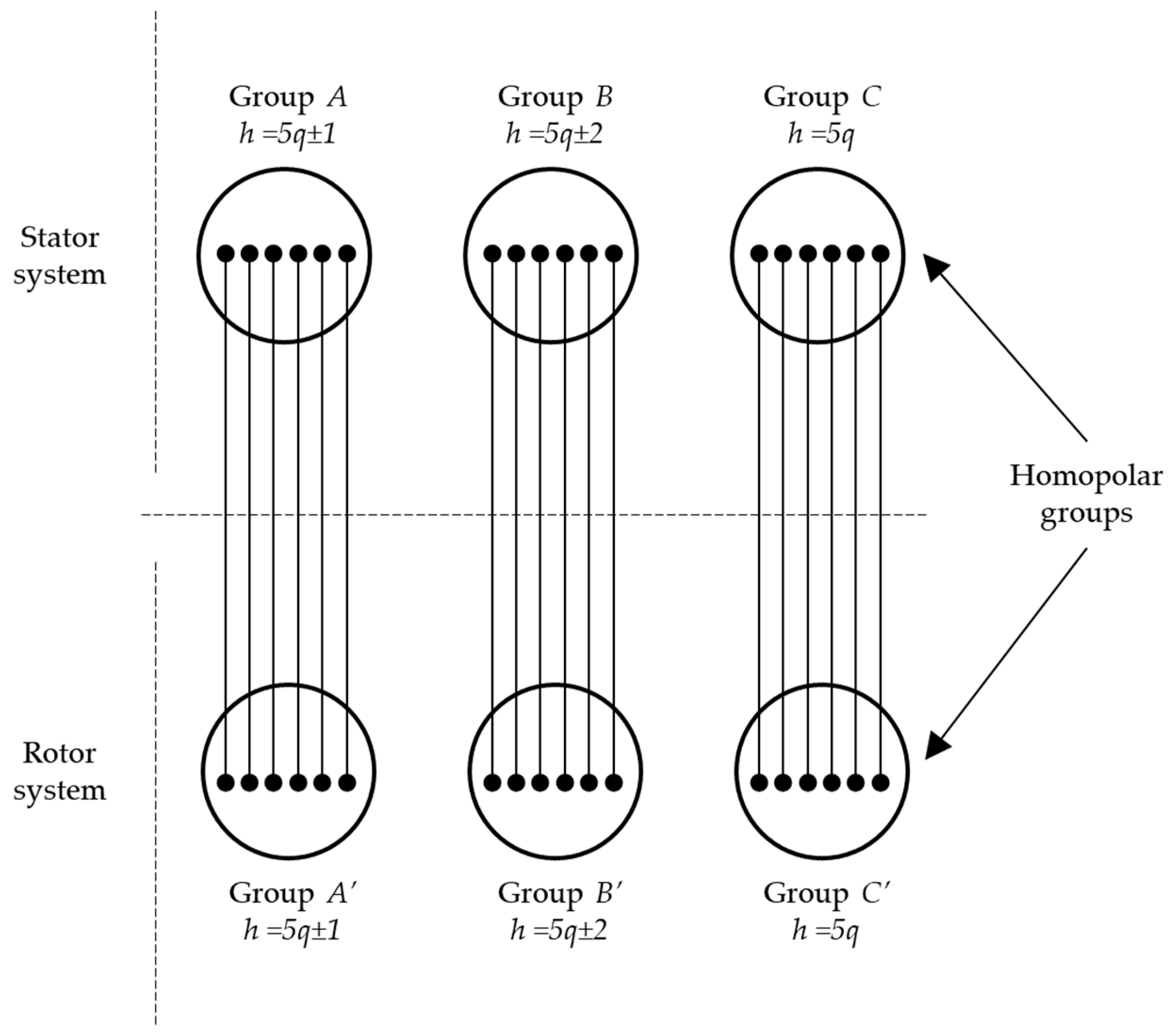
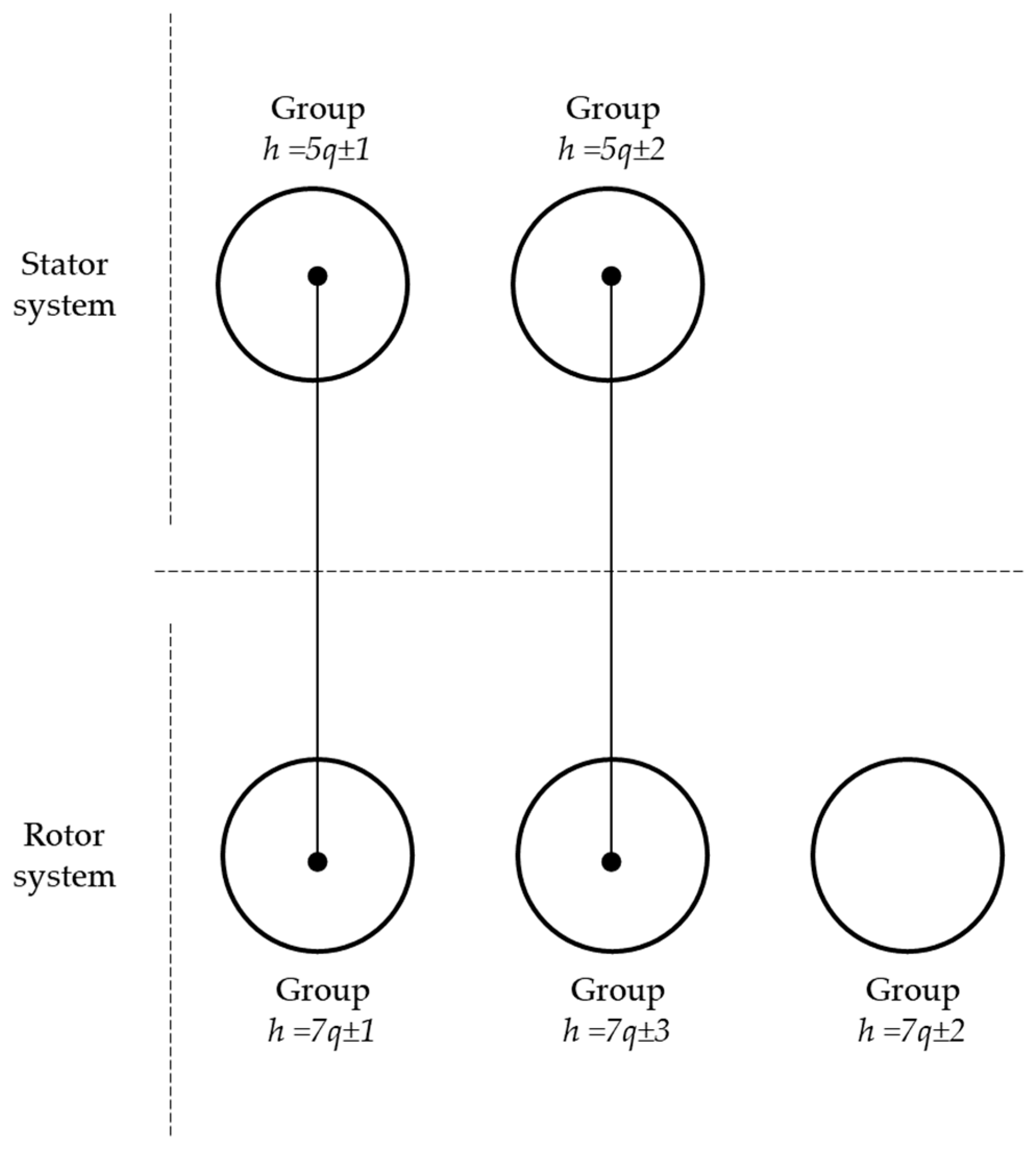
If mstr = mrot, the machine can be decoupled by means of independent groups of space waves (Figure 6)
(b)
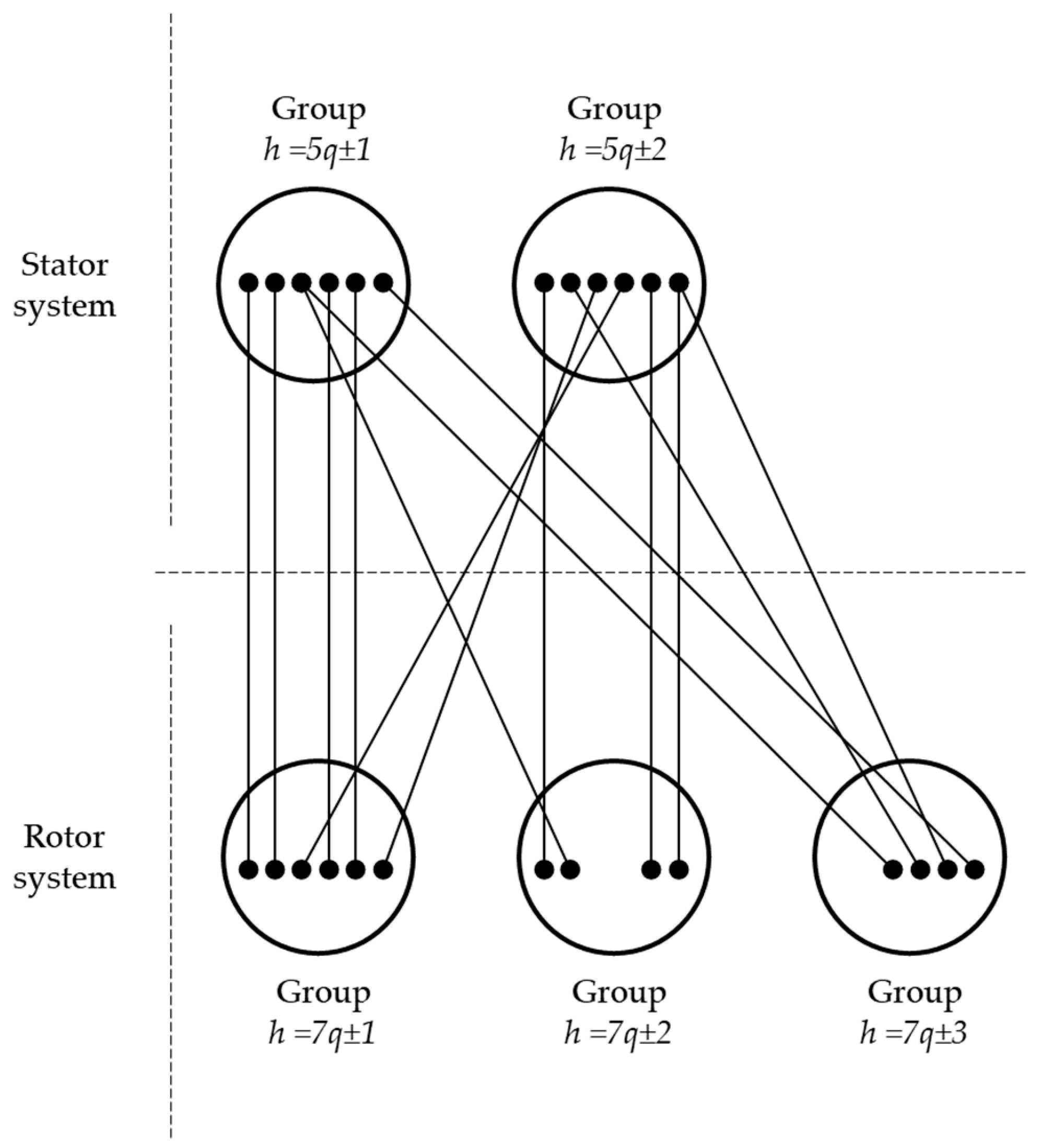
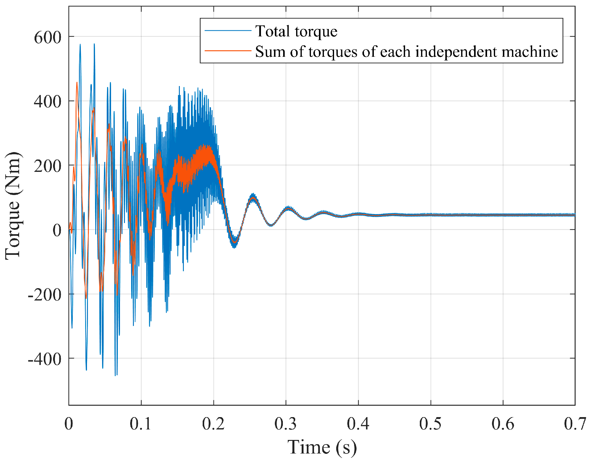
If mstr ≠ mrot, the machine decoupling is not possible because of the cross-coupling between harrmonic groups (Figure 7).
(c)
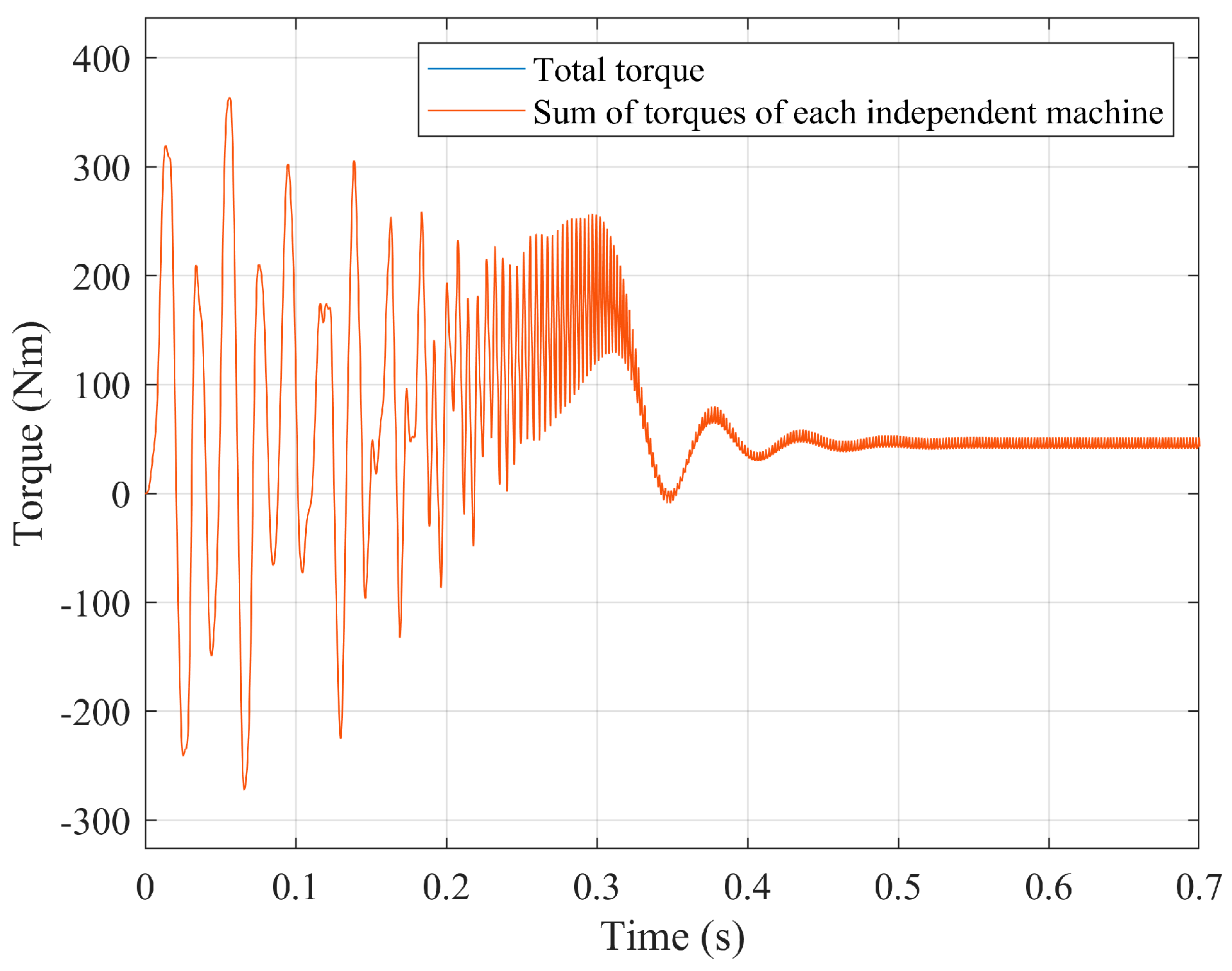
If the machine working region is restricted to the narrow region of very small slips (e.g., converter-controlled machines), it is possible a practical and approxi-mate machine decoupling even if mstr ≠ mrot (Figure 12).
Obviously, it is impossible to deduce these principles from approaches that rely on the absence of harmonic fields (sinusoidally distributed windings).

Appendix B

Table A1. Wound rotor induction motor data.
Stator R = 0.41   Ω L σ = 3.85   mH L μ = 144.44   mH
Rotor R = 0.36   Ω L σ = 2.93   mH L μ = 93.62   mH
Table A2. Squirrel cage induction motor data.
Stator R = 1.25   Ω L σ = 3.57   mH L μ = 191.4   mH
Rotor R b a r = 70   μ Ω L σ , b a r = 0.28   μ H L μ , b a r = 5.63   μ H
R e n d r i n g = 50   μ Ω L σ , e n d r i n g = 0.05   μ H

References

  1. Serrano-Iribarnegaray, L.; Bonet-Jara, J. Physical Meaning of the Multiphase Instantaneous Symmetrical Components and Their Relation to the Space Phasor Theory. In Proceedings of the 2022 International Conference on Electrical Machines (ICEM), Valencia, Spain, 5–8 September 2022; pp. 334–340. [Google Scholar]
  2. Serrano-Iribarnegaray, L. Space phasor theory and control of multiphase machines through their decoupling into equivalent 3-phase machines. Electr. Eng. (Former Arch. Für Elektrotechnik) 2014, 96, 79–94. [Google Scholar] [CrossRef]
  3. Fortescue, C.L. Method of symmetrical co-ordinates applied to the solution of polyphase networks. Trans. Am. Inst. Electr. Eng. 1918, 37, 1027–1140. [Google Scholar] [CrossRef]
  4. Lyon, W.V. Transient Analysis of Alternating-Current Machinery; Technology Press: Cambridge, UK; John Wiley: New York, NY, USA, 1954. [Google Scholar]
  5. Klima, V. Symmetrische Komponenten, ihr Zusammenang mit trigonometrischer Interpolation, Fourierschen Reihen und Vektorkomponenten. Elektrotech. Maschinenbau 1967, 84, 354–365. [Google Scholar]
  6. Hochrainer, A. Symmetrische Komponenten in Drehstromsystemen; Springer: Berlin/Heidelberg, Germany, 1957. [Google Scholar]
  7. White, D.C.; Woodson, H.H. Electromechanical Energy Conversion; John Wiley & Sons: New York, NY, USA, 1959. [Google Scholar]
  8. Kovács, K.P. Symmetrische Komponenten der Momentanwerte, oder Vektoren der elektrische Grössen? Arch. Für Elek. 1960, 45, 99–117. [Google Scholar] [CrossRef]
  9. Kovacs, K.P.; Racz, I. Transiente Vorgänge in Wechselstrom-Maschinen; Akademiai Kiado: Budapest, Hungary, 1959. [Google Scholar]
  10. Park, R.H. Two-Reaction theory of synchronous machines-2. Trans. Am. Inst. Electr. Eng. 1933, 52, 352–355. [Google Scholar] [CrossRef]
  11. Stepina, J. Die Einzelwellen der Felderregerkurve bei unsymme-trischen Asynchronmaschinen. Arch. Für Elek. 1958, 43, 384–402. [Google Scholar] [CrossRef]
  12. Levi, E.; Bojoi, R.; Profumo, F.; Toliyat, H.A.; Williamson, S. Multiphase induction motor drives—A technology status review. IET Electric. Power Appl. 2007, 1, 489–516. [Google Scholar] [CrossRef]
  13. Jones, M.; Levi, E.; Vukosavic, S.N.; Toliyat, H.A. A novel nine-phase four-motor drive system with completely decoupled dynamic control. In Proceedings of the IECON’03. 29th Annual Conference of the IEEE Industrial Electronics Society, Roanoke, VA, USA, 2–6 November 2003; Volume 1, pp. 637–642. [Google Scholar]
  14. Levi, E. Multiphase Electric Machines for Variable-Speed Applications. IEEE Trans. Ind. Electron. 2008, 55, 1893–1909. [Google Scholar] [CrossRef]
  15. Kapp, G. Induction Coils Graphically Treated. Electrician 1887, 18, 502–504, 524–525, 568–571. [Google Scholar]
  16. Feynman, R.; Leighton, R.; Sands, M. The Feynman lectures on physics. In VOL II. Reading; Addison-Wesley: Boston, MA, USA, 1964. [Google Scholar]
  17. Simonyi. Theoretische Elektrotechnik; VEB: Berlin, Germany, 1977. [Google Scholar]
  18. Semail, E.; Bouscayrol, A.; Hautier, J.P. Vectorial formalism for analysis and design of polyphase synchronous machines. Eur. Phys. J. Appl. Phys. 2023, 22, 207–220. [Google Scholar] [CrossRef]
  19. Bonet-Jara, J.; Morinigo-Sotelo, D.; Duque-Perez, O.; Serrano-Iribarnegaray, L.; Pons-Llinares, J. End-Ring Wear in Deep-Well Submersible Motor Pumps. IEEE Trans. Ind. Appl. 2022, 58, 4522–4531. [Google Scholar] [CrossRef]
  20. Echeverría-Villar, J.A.; Martínez-Román, J.; Serrano-Iribarnegaray, L. Transient harmonic torques in induction machines: Measurement and impact on motor performance. Electr. Eng. 2012, 94, 67–80. [Google Scholar] [CrossRef]
  21. Kleinrath, H. Stromrichter Gespeiste Drehfeldmaschinen; Springer: Wien, Austria, 1980. [Google Scholar]
  22. Figueroa, J.; Cros, J.; Viarouge, P. Generalized transformations for polyphase phase-Modulation motors. IEEE Trans. Energy Convers. 2006, 21, 332–341. [Google Scholar] [CrossRef]
  23. O’Rourke, C.J.; Qasim, M.M.; Overlin, M.R.; Kirtley, J.L. A Geometric Interpretation of Reference Frames and Transformations: dq0, Clarke, and Park. IEEE Trans. Energy Convers. 2019, 34, 2070–2083. [Google Scholar] [CrossRef]
  24. Stepina, J. Raumzeiger als Grundlage der Theorie del elektrischen Maschinen. ETZ-A 1967, 88, 584–588. [Google Scholar]
  25. Zhao, Y.; Lipo, T.A. Space vector PWM control of dual three-phase induction machine using vector space decomposition. IEEE Trans. Ind. Appl. 1995, 31, 1100–1109. [Google Scholar] [CrossRef]
Figure 1. Relationship between a time phasor and a sinusoidal wave.
Machines 13 00107 g001
Figure 2. Phase positions of a 7-phase winding: (a) actual positions; (b) fictitious positions for the projections of a dynamic time phasor with sequence g = 3.
Machines 13 00107 g002
Figure 3. Flux linking an arbitrary stator coil of a salient pole machine.
Machines 13 00107 g003
Figure 4. Space wave of five pole pairs in the machine domain (left) and its space phasor in the corresponding phasorial domain (right).
Machines 13 00107 g004
Figure 5. Geometric interpretation of Equation (19).
Machines 13 00107 g005
Figure 6. Schematic diagram of the harmonic fields’ interactions with regard to the total torque production in a 5-phase machine with mstr = mrot. All stator or rotor harmonic waves of relative order h = 5q ± 1 belong to the same group, A or A’, respectively. An analogous statement applies to the space waves with h = 5q ± 2 (groups B and B’) and with h = 5q (homopolar waves, groups C and C’).
Machines 13 00107 g006
Figure 7. Cross-coupling between harmonic fields of stator and rotor in a multiphase machine with mstr = 5 ≠ mrot = 7 and without homopolar fields.
Machines 13 00107 g007
Figure 8. Direct start-up of a wound induction motor with mstr = mrot = 5.
Machines 13 00107 g008
Figure 9. Direct start-up of a wound induction motor with mstr = 5 ≠mrot = 7.
Machines 13 00107 g009
Figure 10. Direct start-up of a squirrel-cage motor mstr = mrot = 7.
Machines 13 00107 g010
Figure 11. Direct start-up of a squirrel-cage motor mstr = 7 ≠mrot= 11.
Machines 13 00107 g011
Figure 12. Machine with mstr = 5, mrot = 7 and without homopolar fields. Schematic diagram as to the total torque production under the simplified assumption that the stator–rotor magnetic coupling takes place only through the head members of each wave group. This assumption is only acceptable in the narrow region of very small slips.
Machines 13 00107 g012
Disclaimer/Publisher’s Note: The statements, opinions and data contained in all publications are solely those of the individual author(s) and contributor(s) and not of MDPI and/or the editor(s). MDPI and/or the editor(s) disclaim responsibility for any injury to people or property resulting from any ideas, methods, instructions or products referred to in the content.

