Abstract
This study proposes an active stability control method for the multi-link mechanism of spraying equipment to enhance its spraying performance. Traditional spraying operations typically focus on protecting only the tops of crops, whereas the multi-link mechanism can adjust the angle and position of the nozzles in coordination, achieving comprehensive protection for the crops. However, the characteristic of uneven output speed in the multi-link mechanism results in variations in the spraying amount at different positions. To address this issue, this study developed a method for actively adjusting the stability of the output end speed. First, a differential equation was established to relate the input speed to the output speed using vector methods, implicit function transformation to explicit functions, and regression analysis. The feasibility of this method was verified through simulations using MATLAB Simulink R2018a and Adams 2018. Prototype test results indicate that this speed adjustment method improved the stability of the output angular velocity, reducing the coverage rate variation between the upward, sideways, and downward of the leaves by 12.53% during the spraying process. Therefore, the method proposed in this study can enhance the uniformity of spraying, further improving the utilization of pesticides, which is beneficial for the green ecological sustainable development in the agricultural field. Additionally, this control method is also applicable to other types of link mechanisms, providing a reference for improving the output stability of link mechanisms.
1. Introduction
The application of pesticides is essential for the growth and development of agricultural crops. With the advancement of various technological innovations, the methods for pesticide application have evolved significantly, transitioning from traditional backpack sprayers to modern robotic sprayers [1,2]. Conventional pesticide application techniques typically utilize a blanket spraying method that employs high volumes of chemicals to enhance efficacy. In contrast, contemporary advancements in spraying technology primarily focus on pesticide conservation and application precision [3,4]. To improve pesticide efficiency, protect the environment, and ensure accurate delivery, researchers have developed a range of spraying devices and methodologies. These innovations include electrostatic pesticide spraying [5], air-assisted spraying technology [6], machine learning-driven targeted spraying systems [7], and adjustable linkage mechanisms [8,9]. Electrostatic pesticide spraying technology utilizes the principle of electrostatic adsorption to enhance the deposition rate of droplets, thereby improving their adherence to crop surfaces [10]. The air-assisted spray technology utilizes forced airflow to manipulate the structure of crop leaves, thereby enhancing the penetration of droplets into the inner layers of the vegetation. This process also flips the leaves, improving the deposition of droplets on the undersides and lower-middle regions of the leaves [11]. Collectively, these technologies aim to optimize pesticide usage by increasing the coverage of the pesticide solution. Additionally, machine learning and targeted spraying systems can enable the automatic online classification and identification of target crops and weeds by integrating crop data with visual technology, thus enhancing the precision of pesticide application on designated crops [12]. However, the implementation of such systems often requires a high degree of freedom spraying actuators, such as robotic arms [13], which can complicate operations and increase costs. In contrast, adjustable linkages provide a wider range of application scenarios compared to robotic arms [14,15].
The linkage mechanism is a system composed of several interconnected links connected by joints. It is commonly used to facilitate complex motion trajectories that generate dynamic characteristics [16,17]. This mechanism demonstrates a variety of motion modes, allowing it to execute rotations, oscillations, translations, and complex movements within either a planar or three-dimensional environment. Such versatility facilitates the implementation of established motion laws and predetermined trajectories. Additionally, by modifying the number and length of the linkages, the mechanism can generate a wide range of output types [18,19]. This adaptability permits the linkage mechanism to conform to various application contexts and specifications [20]. The primary design methodologies for linkage structures include graphical methods [21], analytical methods [22], and numerical methods [23]. These approaches generally impose constraints on the parameters of the linkage mechanism by considering the positions of the target points along the trajectory of the output end [24,25]. However, the speed and acceleration of the output end are often overlooked, complicating the design and implementation of the linkage mechanism. After the design phase, it is typically necessary to analyze and verify the mechanism’s dynamic characteristics [26]. If these characteristics do not meet the established design criteria, it may be necessary to optimize the parameters or, in some cases, undertake a comprehensive redesign of the mechanism. Therefore, the linkage mechanism frequently encounters the issue of inconsistent output speed in practical applications. When integrated with the spraying system, this inconsistency results in significant variations in the coverage of the spraying equipment across different areas of the crops. Such disparities not only hinder the effective utilization of pesticides but also challenge the comprehensive protection of the crops.
The control methodology employed for the linkage mechanism serves as a critical foundation for ensuring stable transmission. Traditional approaches predominantly utilize closed-loop control systems [13,27], in which sensors are integrated at the nozzle position to facilitate real-time monitoring and adjustment of the angular velocity of the spraying linkage. However, this control strategy is characterized by a certain degree of latency and involves a relatively complex system architecture. Closed-loop control is frequently employed in situations where the output load is substantial and continuously fluctuating. In the context of the linkage mechanism examined in this study, the variations in load at the output end of the linkage are minimal. Consequently, this study proposes an active control strategy for multi-linkage sprayers, which enables uniform adjustment of the spraying linkage angle. This innovation is anticipated to enhance the uniformity of spraying and contribute positively to the principles of ecological sustainability within the agricultural sector.
Based on the analysis presented above, the application of a linkage mechanism to a sprayer can collaboratively adjust the angle and position of the nozzles, demonstrating significant potential for comprehensive crop protection. However, multi-link mechanisms encounter the challenge of uneven output speeds in practical applications, which directly results in inconsistencies in the amount of spray delivered at different positions. To address this issue, this study aims to develop an active stability control method for a multi-link structure sprayer to enhance the uniformity of spraying. The research focuses on actively adjusting the output speed of the spraying equipment through precise mathematical modeling and the design of control strategies to achieve uniform application. The core of this method involves establishing a relationship model between input speed and output speed using differential equations, along with vector methods, implicit function transformation to explicit functions, and regression analysis, thereby providing a comprehensive solution that bridges theory and practice. This research not only presents a novel approach to resolving the existing challenges associated with multi-link spraying equipment, in alignment with global trends toward sustainable development and green ecological agriculture, but also serves as a reference for the stability control of other complex mechanical structures, showcasing significant application potential.
2. Materials and Methods
2.1. Structure and Principle of Multi-Link Spraying Machine
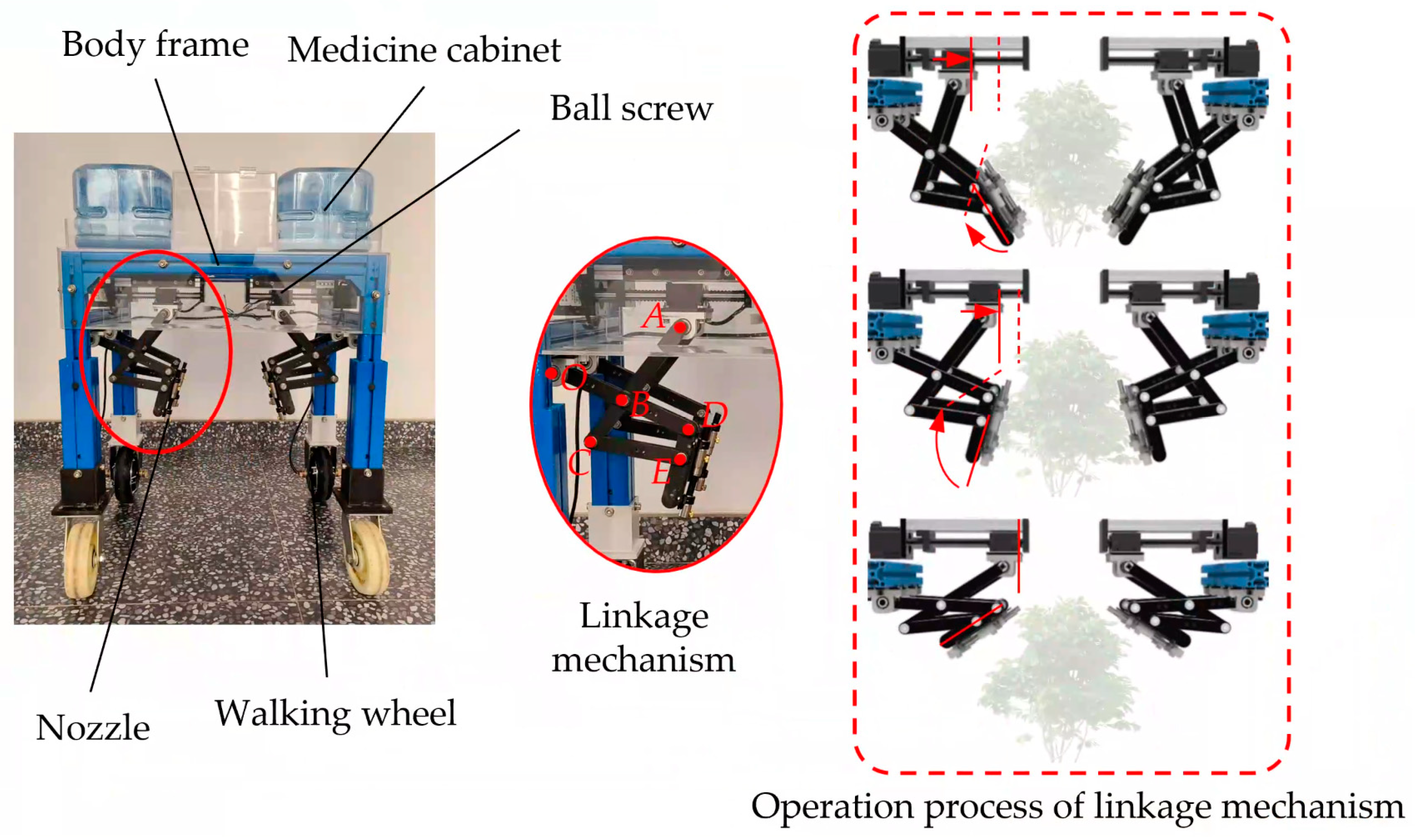
The research group has developed a spraying machine that precisely controls the position and angle of the nozzle through a linkage system. This design facilitates thorough spraying on the upper, lateral, and undersides of crop leaves. The primary structure is illustrated in Figure 1, which comprises a body frame, linkage mechanisms, medicine cabinets, walking wheels, and several additional components. The input point of the linkage mechanism is designated as point A, with power management facilitated by a ball screw. The nozzle is attached to link DE, which serves as the output of the linkage mechanism [28].
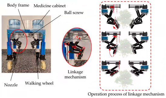
Figure 1.
Configuration and operational principles of the multi-link mechanisms sprayer. Note: Points O, A, B, C, D, and E represent the hinge positions, while the arrows indicate the direction of motion.
When the drive motor of the ball screw operates at a constant velocity, the slider translates uniformly along the screw axis in conjunction with input point A of the linkage mechanism. The interaction among various linkages results in continuous alterations in the position and angle of linkage DE, which, in turn, regulates the position and spray angle of the nozzle.
2.2. Modeling and Analysis of Linkage Mechanism
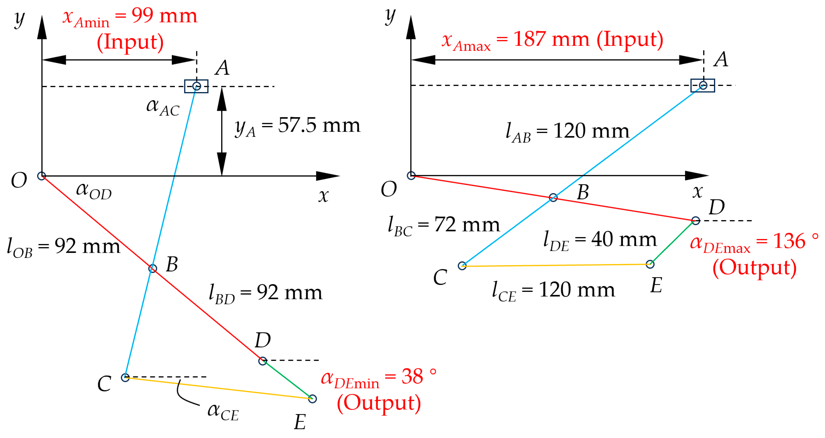
To establish the relationship between the input (position of slider A) and the output (nozzle connecting rod angle), a modeling analysis of the multi-link mechanisms was conducted. The fixed hinge point O of the linkage OD was designated as the origin of the coordinate system, with the horizontal axis oriented towards the crop defined as the x-axis and the vertical axis directed upwards from the ground defined as the y-axis. This configuration establishes a Cartesian coordinate framework, as illustrated in Figure 2. Following an initial design and optimization analysis, the dimensions of the connecting rods have been determined as follows: the length of the OD connecting rod is 184 mm (with the OB segment measuring 92 mm), the length of the AC connecting rod is 192 mm (with the AB segment measuring 120 mm), the length of the CE connecting rod is 120 mm, the length of the DE connecting rod is 40 mm, and the distance from point O to the screw axis is 57.5 mm [29].
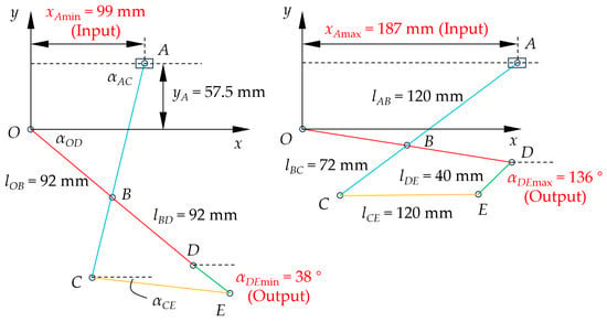
Figure 2.
Modeling and analysis of multi-link mechanisms.
In order to clarify the functional relationship between the input and output variables of the linkage mechanism, a parametric modeling analysis of the linkage structure was conducted. First, the vector approach was utilized to derive the position equations for points B and E [29]:
Note: rOB represents the vector associated with the OB; rOA denotes the vector corresponding to the OA; rAB signifies the vector for the AB, rBC indicates the vector related to the BC; rCE refers to the vector of the CE; rBD represents the vector pertaining to the BD; rDE denotes the vector associated with the DE.
Through the application of orthogonal decomposition to Equation (1) in both the x and y directions, the following results were obtained:
In this context,
Note: (xA, yA) represents the coordinates of endpoint A in the xOy coordinate system, mm; (xC, yC) denotes the coordinates of endpoint C in the xOy coordinate system, mm; (xD, yD) indicates the coordinates of endpoint D in the xOy coordinate system, mm; lAB refers to the length of the AB connecting rod, mm; lOB is the length of the OB connecting rod, mm; lCE represents the length of the CE connecting rod, mm; lDE denotes the length of the DE connecting rod, mm; lAC indicates the length of the AC connecting rod, mm; lOD refers to the length of the OD connecting rod, mm; αAC is the angle between the AC connecting rod and x-negative direction, °; αOD is the angle between the OD connecting rod and the positive x-direction, °; αCE is the angle between the CE connecting rod and the positive x-direction, °; αDE is the angle between the DE connecting rod and the positive x-direction, °.
By integrating Equation (2), the correlation between the lateral displacement position xA of the slider at point A and the angles αAC, αOD, and αDE were derived.
2.3. Establishing Explicit Function Equations and Curve Fitting
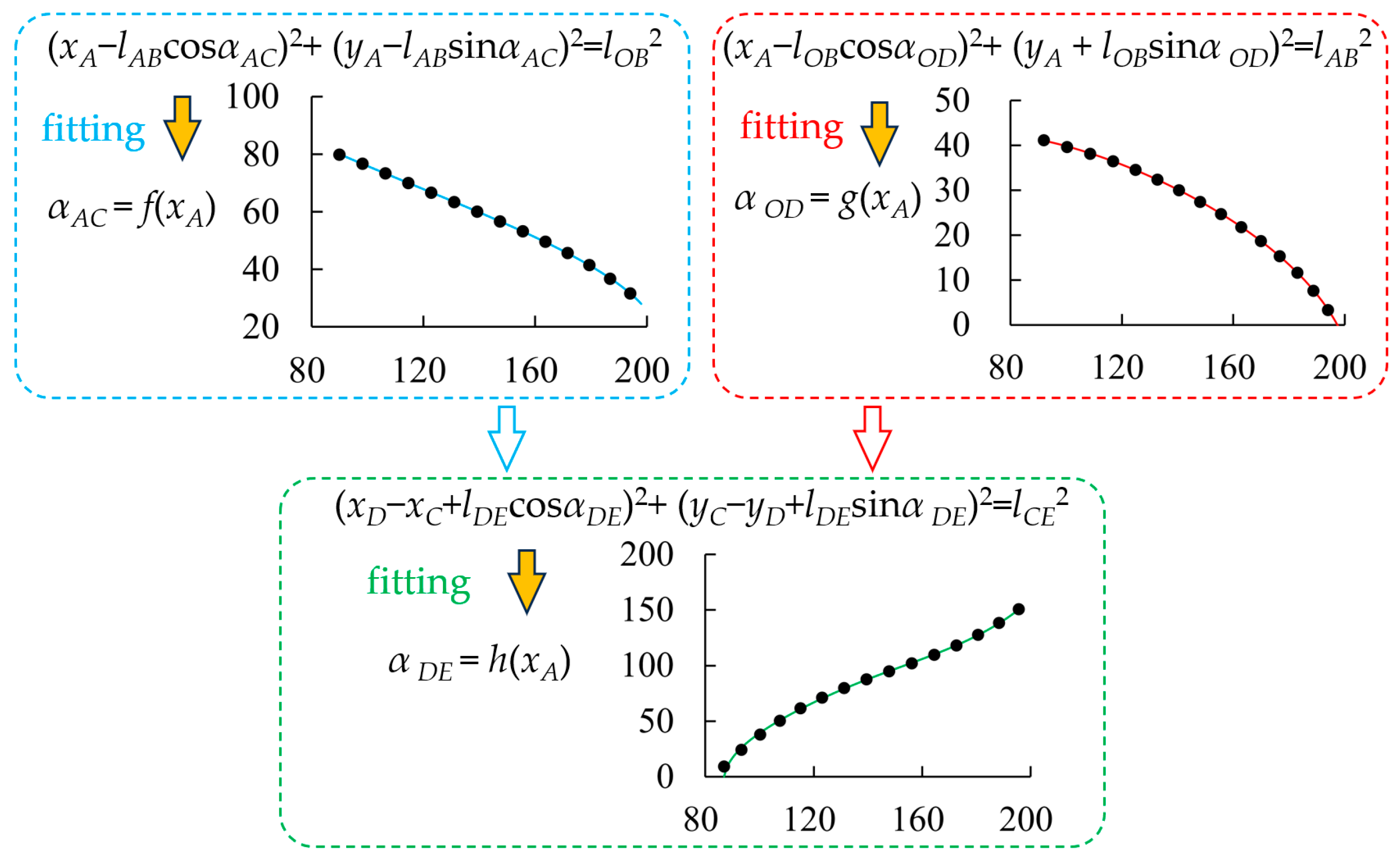
In Equation (3), the lengths of each rod and the vertical coordinate yA of point A are defined parameters. The angles corresponding to rods AC, OD, and CE exhibit a nonlinear relationship with respect to xA. However, Equation (3) represents an implicit function, which complicates the calculation of the derivative of the functional relationship between the input speed vA and the output speed ωDE. Therefore, to isolate the independent variable xA and the dependent variable αDE in the implicit function equation, it is essential to conduct nonlinear fitting on the three implicit function equations presented in Equation (3) to transform them into explicit functions [30,31]. The objective is to achieve a coefficient of determination greater than 0.99, which will facilitate the identification of the highest degree of the fitting equation. The computational approach is illustrated in Figure 3, and the resulting data are presented in Table 1.
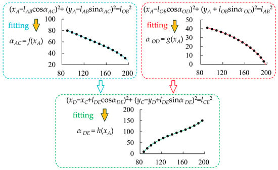
Figure 3.
Explicit function equation and fitting process.

Table 1.
Fitting results of explicit function equation..
To establish the relationship between the velocity of slider and the angular velocity of the nozzle connecting rod, it is necessary to compute the derivative of the fitting equation h(xA) with respect to both xA and αDE.
Note: vA represents the velocity of slider A, mm/s; ωDE denotes the angular velocity of the nozzle connecting rod, °/s. C1, C2, and C3 are fitting parameters, with their values detailed in Table 1.
2.4. Verification of Consistency Between Simulink and Adams Models
Utilizing the MATLAB Simulink R2018a module to address Equation (4) [32,33], and based on the structural analysis of the device, it is observed that when the horizontal coordinate xA of the slider in the ball screw varies between 99 mm and 187 mm, the corresponding range of rotation angles for the spraying connecting rod DE spans from 38° to 136°.
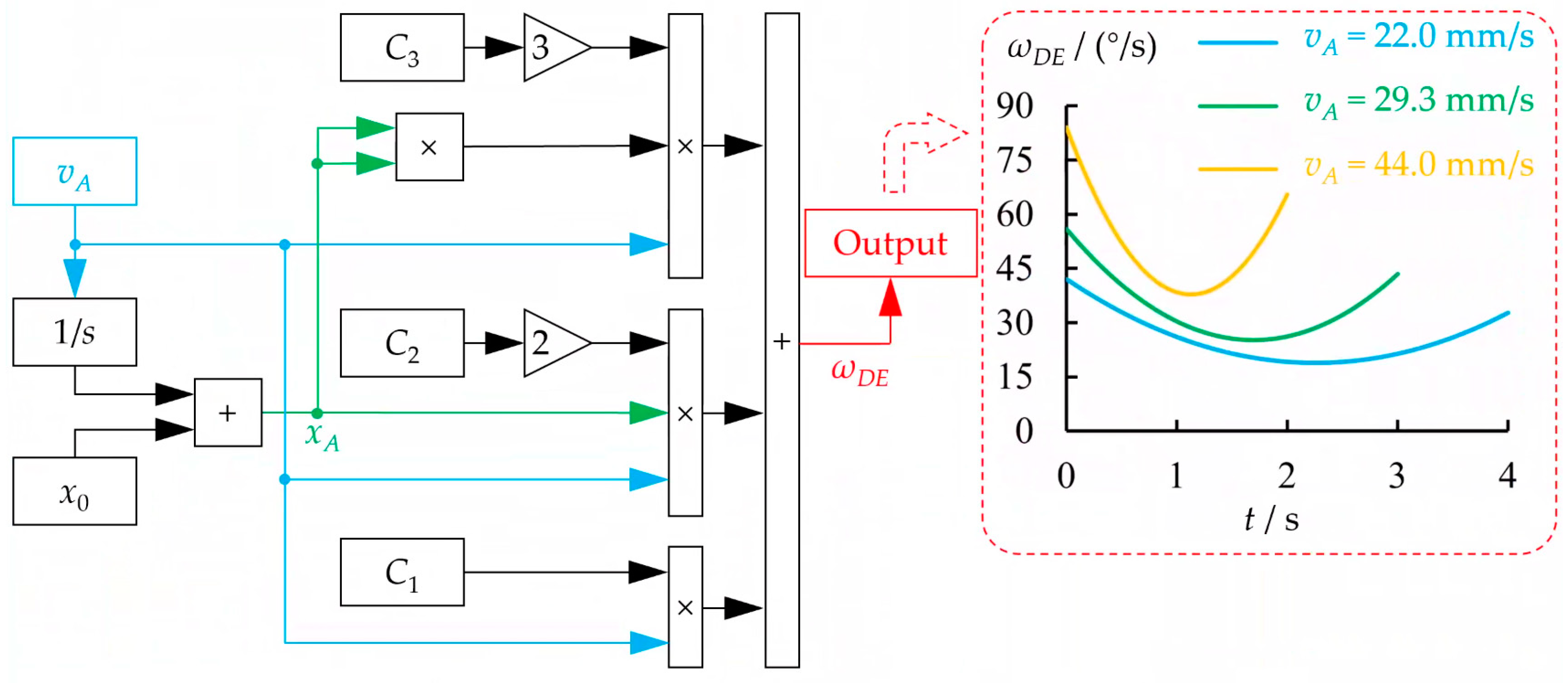
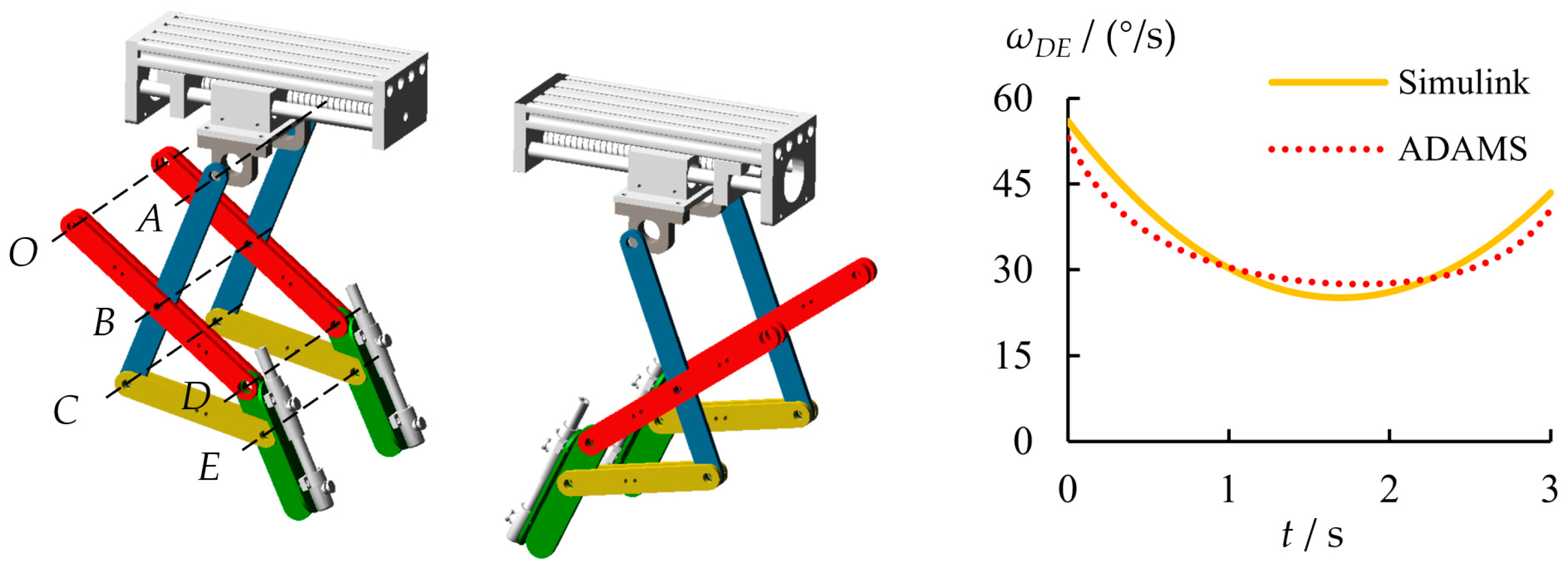
The multi-link angle spraying machine discussed in this study is specifically designed for greenhouse planting environments. In contrast to large-scale outdoor farmland, greenhouse planting allows for precise control over environmental factors such as temperature, humidity, and light, thereby creating optimal growth conditions for crops. However, the relatively enclosed nature of greenhouses also creates favorable air and soil conditions that can promote the survival and reproduction of pests and diseases. Consequently, the effective utilization of pesticides and the precision of spraying are more critical than operational efficiency [13,34]. Preliminary research indicates that if the speed of the linkage mechanism is excessively fast, it can lead to pesticide drift and negatively impact the dynamic characteristics of the mechanism. Therefore, this study examines single run times of 2, 3, and 4 s as examples, sacrificing some operational efficiency to achieve more effective spraying results. Based on the rotation angles of rod DE and single run time, the vA values were calculated to be 44.0, 29.3, and 22.0 mm/s. The graphical representation and results are depicted in Figure 4, which demonstrates the temporal variation of the angular velocity ωDE of the spraying connecting rod DE with time under different parameters. The angular velocity of the connecting rod DE exhibits a pattern of initial decline followed by an increase, reaching a maximum speed of approximately 1.91 × vA °/s at t = 0, and a minimum speed of about 0.86 × vA °/s at t = 49.7/vA s.
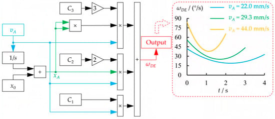
Figure 4.
Model and outcomes of the ωDE solver utilizing Simulink.
To validate the accuracy of the solution model, the dynamic analysis software Adams 2018 was employed to simulate the motion characteristics of the multi-link mechanisms [35,36]. SolidWorks was utilized to effectively simplify the ball screw and multi-link mechanisms by omitting minor components, such as bolts, that do not significantly influence the simulation outcomes. The resulting simplified model was subsequently imported into Adams, and constraints, drives, and marking points were reasonably added. The ball screw utilized in this investigation has a lead of 10 mm. Taking a running time of 3 s as an example, when the velocity vA was set at 29.3 mm/s, the corresponding motor speed generated by the ball screw was calculated to be 175.8 r/min. Utilizing this information, the drive parameters were established, and the variation curve of the output value ωDE of the multi-link mechanism is illustrated in Figure 5. A comparative analysis of the simulation outcomes from Simulink and those from Adams reveals that the trends and inflection points of both curves are largely congruent, thereby affirming the validity of the theoretical model and the results derived from Simulink.
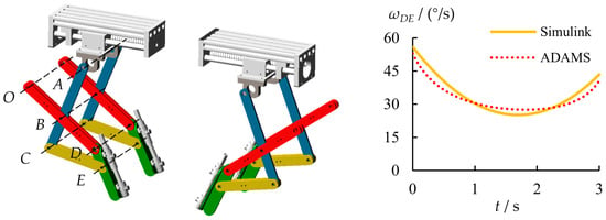
Figure 5.
Adams model and Simulink simulation results. Note: O, A, B, C, D, and E represent the positions of the hinge pivot axis.
2.5. Solving Input Functions Based on Simulink
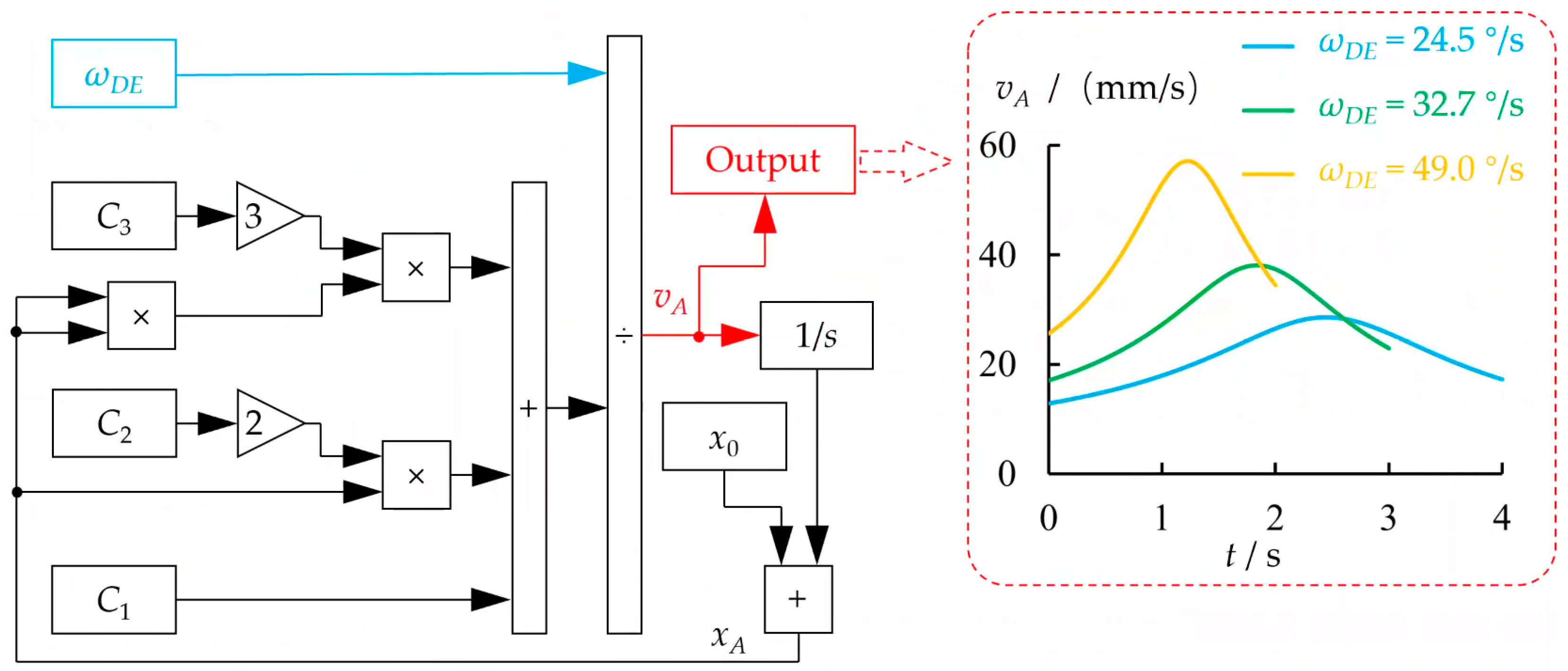
As illustrated in Figure 4, when the slider moves at a constant speed, the angular velocity of connecting rod DE exhibits non-uniformity. This variation leads to differences in the concentration of the pesticide solution being sprayed at various positions during actual spraying operations. To achieve a uniform and stable application of the pesticide solution, a reverse correction of the driving characteristics at the moving end was implemented. This process involves the active adjustment of vA, which is assigned a nonlinear variation, thereby ensuring that the angular velocity of the nozzle mounting rod DE remains constant. The Simulink model corresponding to Equation (4) has been revised and constructed, with the nozzle angle adjustment range established between 38° and 136°. Based on simulation durations of 2, 3, and 4 s, the angular velocity ωDE of the connecting rod DE for the nozzle installation, maintained at a constant velocity, have been determined to be 49.0, 32.7, and 24.5°/s, respectively. The graphical representation of the model and the corresponding results are shown in Figure 6. When the target angular velocity of the connecting rod DE for the nozzle installation is held constant, the input speed vA of the slider exhibits a pattern of initial increase followed by a decrease. The peak speed is approximately 1.17 × ωDE mm/s, occurring at t = 60.03/ωDE s.
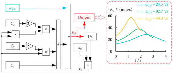
Figure 6.
Model and outcomes of the vA solver utilizing Simulink.
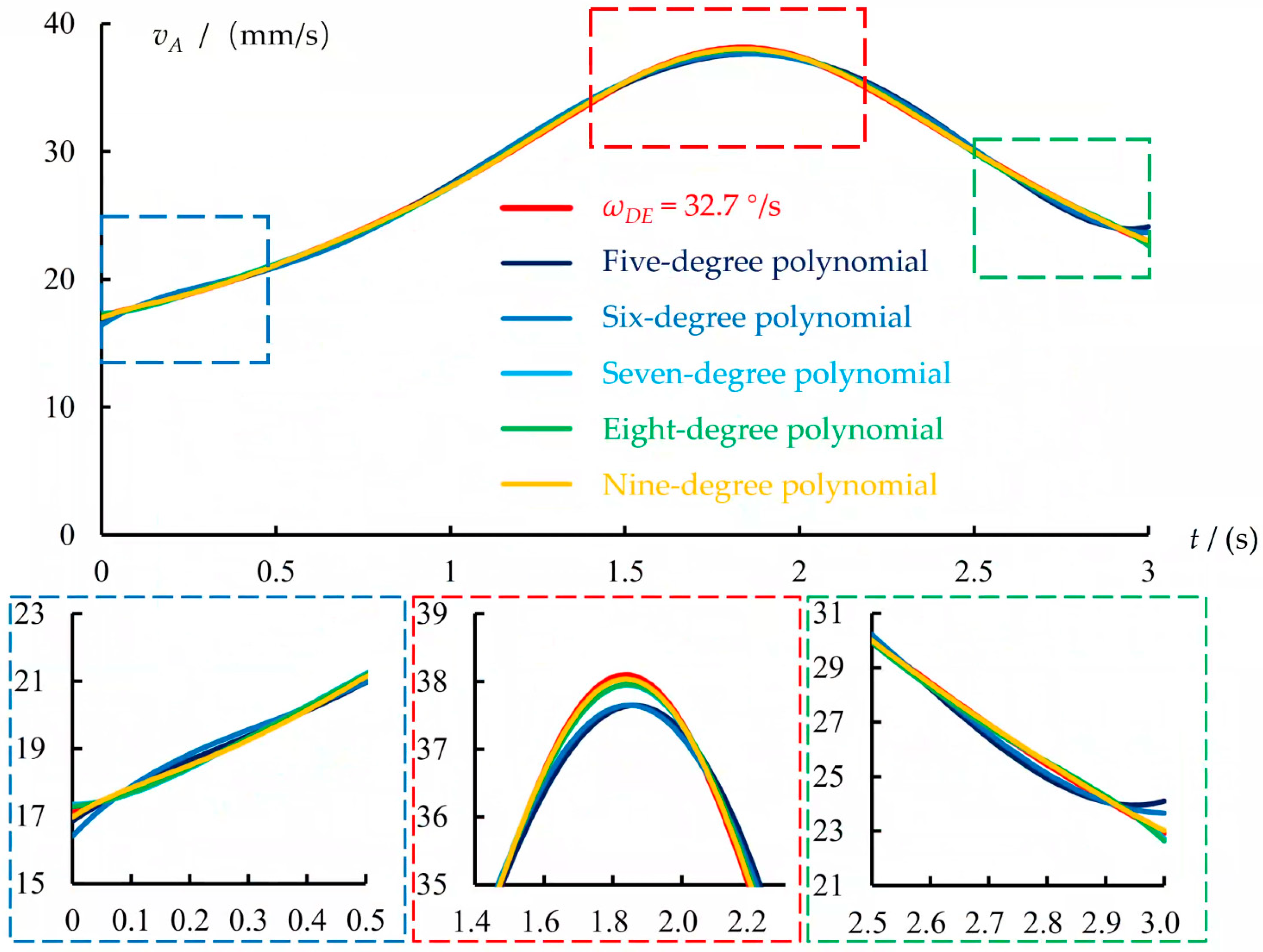
A polynomial representation of vA, expressed as vA = ΣDiti, was developed based on the nonlinear input curve of vA across various parameters. For clarity, a single runtime of 3 s was utilized to fit the variation curve of vA, as depicted in Figure 7. To ensure a coefficient of determination exceeding 0.99 for the fitting equation, it was established that the polynomial must possess a minimum degree of 5. In order to fit the model to the target curve as closely as possible, the degree of the fitting equation was constrained to a range between 5 and 9. The final results of the fitting process are presented in Table 2, indicating that uniform control at the output end can be theoretically attained.
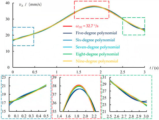
Figure 7.
Fitting results at ωDE = 32.7°/s.

Table 2.
Fitting results of different degree polynomial.
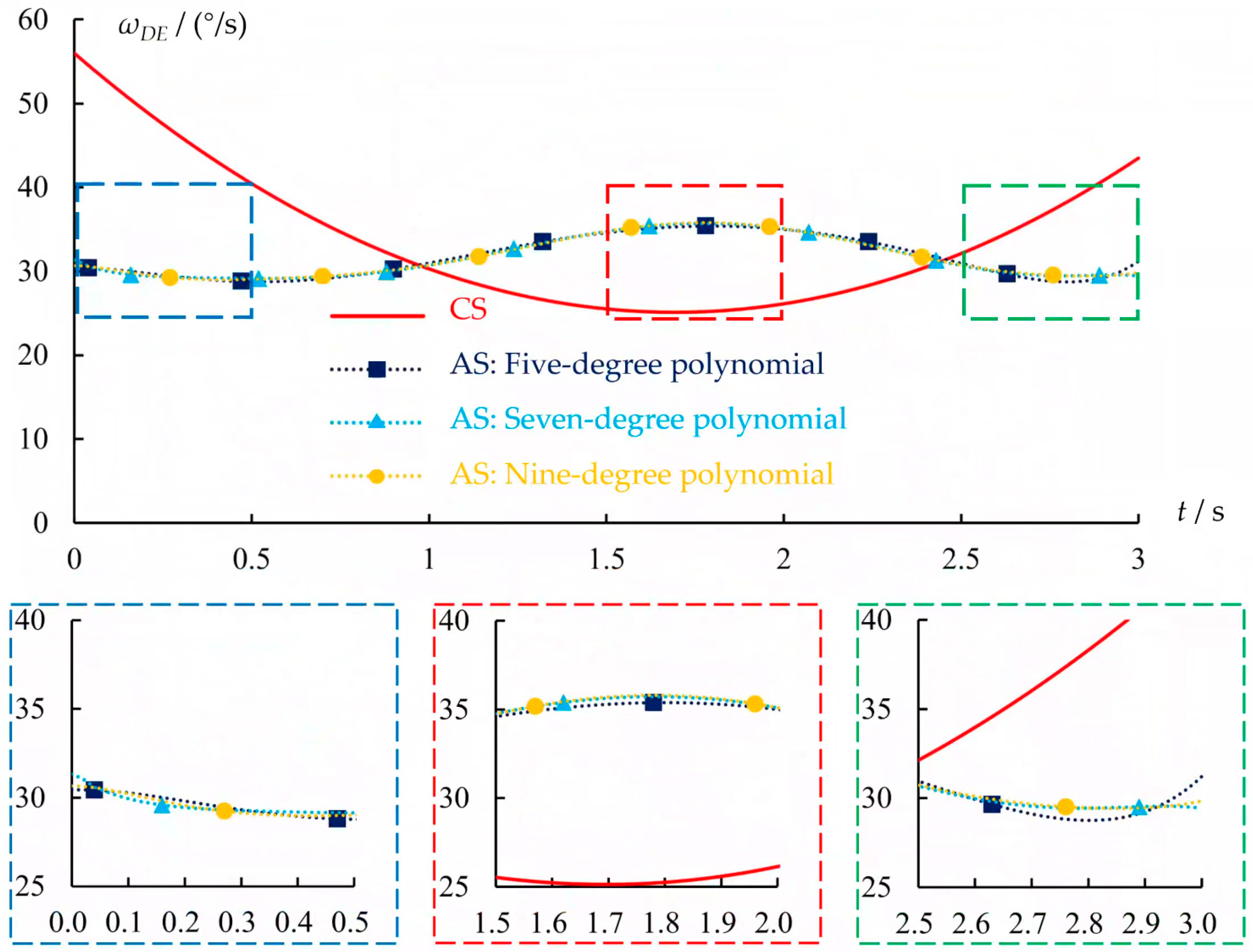
The motion characteristics of the output end of the linkage mechanism were validated using Adams, with the input end subjected to both constant speed (CS) and adjusted speed (AS) motions. When the velocity of the slider was input according to the fitting equation presented in Table 2, the variation curve of the output value ωDE for the multi-link mechanism was illustrated in Figure 8. It is evident that, in comparison to the CS curve, the stability of the AS curves corresponding to different fitting intervals has improved. Nonetheless, due to inherent inaccuracies in the fitting equations, the AS curve continues to display minor fluctuations. The trends observed in the curves derived from various fitting intervals are generally consistent, with discrepancies primarily evident in the terminal data. Notably, the AS curves resulting from the 5- and 7-degree polynomials exhibit reduced fluctuations at the end when compared to the 9-degree polynomial.
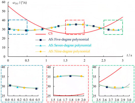
Figure 8.
Simulation results of ωDE output based on Adams.
3. Testing, Results, and Analysis
3.1. Testing Plan
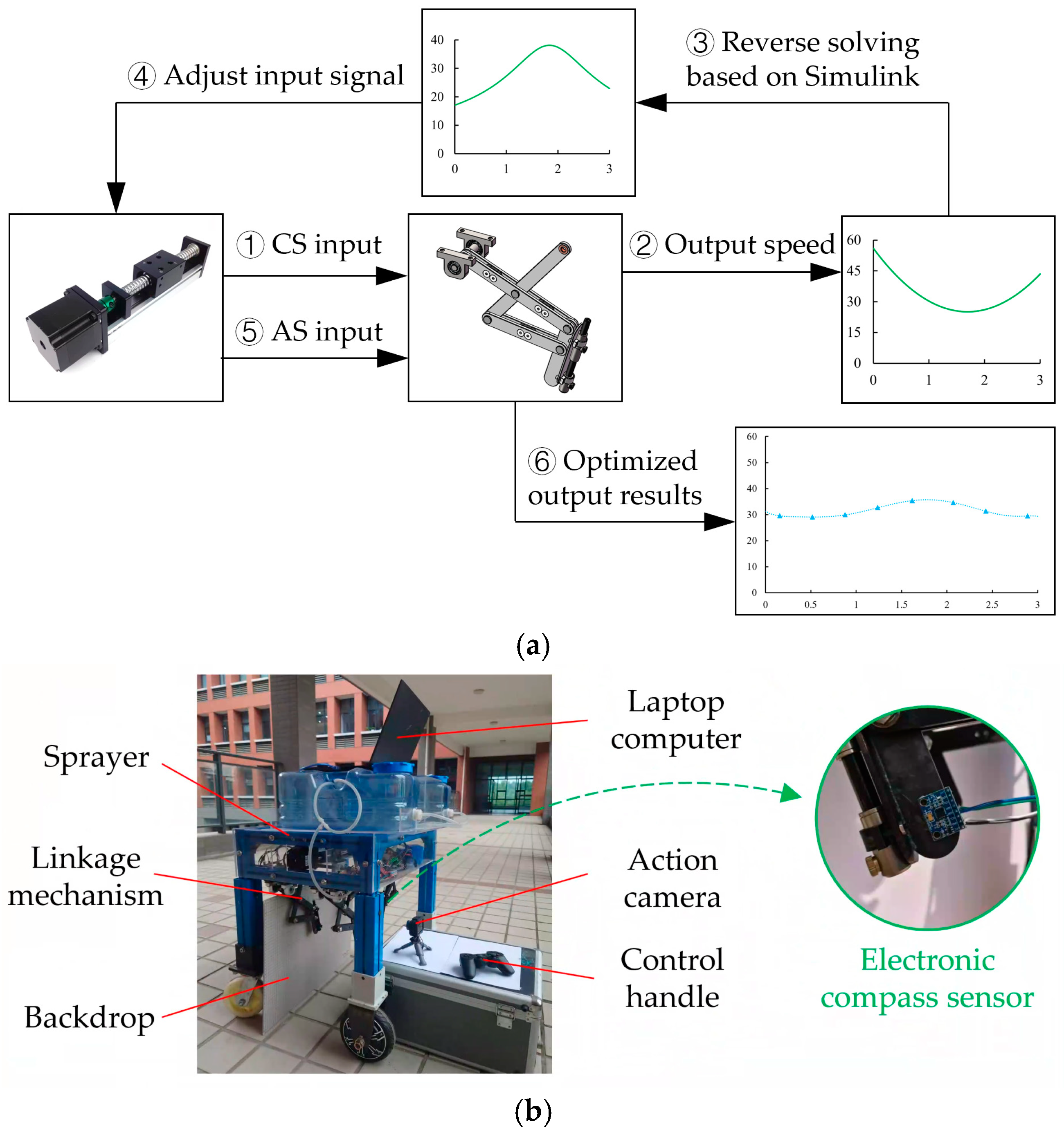
To evaluate the motion response characteristics of the output end of the multi-link spraying mechanism, a series of comparative tests were conducted. The active control process and testing configuration are depicted in Figure 9. The input end of the multi-link spraying mechanism is driven by a motor through a ball screw with a screw pitch of 10 mm. The desired rotational speed of the motor for the tests is determined based on the speed and pitch of slider A, with control signals transmitted to the motor via an Arduino interface [37,38]. The rotation angle of the spraying connecting rod DE serves as the output terminal of the multi-link spraying mechanism. An electronic compass sensor was attached to the spraying connecting rod DE to measure the angular velocity at the output end, with a designated sampling interval of 0.1 s.
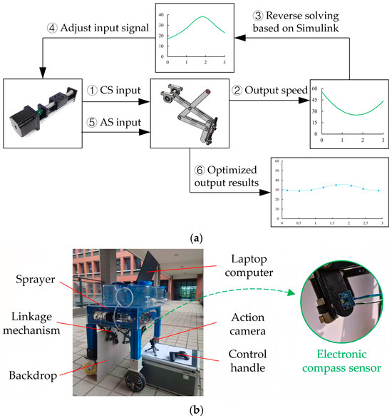
Figure 9.
Schematic representation of testing layout: (a) active control process; (b) testing configuration.
Using a target speed of ωDE = 32.7°/s and a test duration of 3 s as a case study, the stepper motor was initially configured using the DM542 driver (manufactured by Wenzhou Pfede Electromechanical Co., Ltd. in Wenzhou, China) to ensure the accuracy of the feedback data during the testing process. First, a multimeter is used to measure and calibrate the input voltage of the driver to 24 V. Next, to ensure the accuracy of the Adams simulation and the consistency of the variables with the actual measured results, the input signal frequency is set to 0.01 s based on the Adams simulation step size. Finally, the motor input is regulated to operate in accordance with the control signals CS and AS. The speed-driving curve of the motor associated with AS was established using the 7-degree polynomial equation presented in Table 2. The relationship between motor speed and slider speed within the ball screw system is described by Equation (5).
Note: n represents the rotational speed of the motor, r/min; P denotes the pitch of the ball screw, which is established at 10 mm in this study.
The rotation angle of the spray installation’s connecting rod DE was determined through video recording. The data collected from the electronic compass sensor was then analyzed to validate the accuracy of the employed research methodology.
3.2. Comparison and Analysis of Angular Velocity Between CS and AS
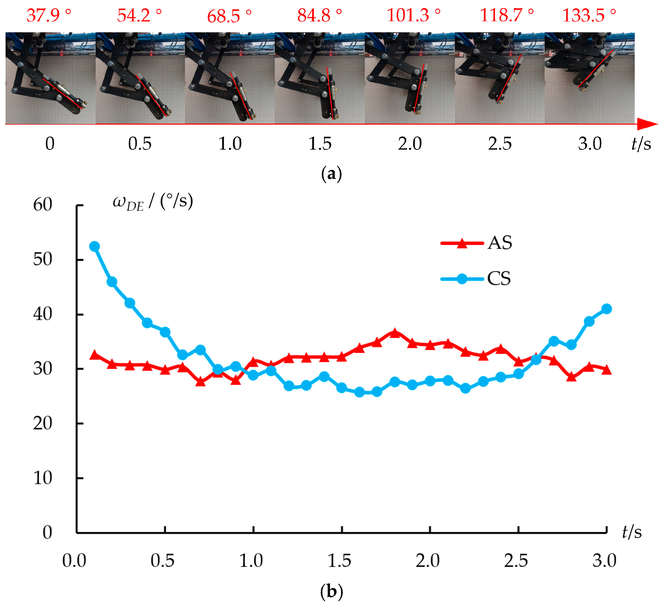
The test parameters of CS were that the driving motor operates at a constant speed of 175.8 r/min (corresponding to a slider speed of 29.3 mm/s). According to the fitting equation provided in Table 2 and Equation (5), AS drives the motor at variable speeds. Specifically, the driving equation is n= (−1.570 × t7 + 15.899 × t6 – 60.622 × t5 + 107.779 × t4 – 93.733 × t3 + 42.205 × t2 – 0.071 × t + 17.343) × 60/10. The resultant test outcomes are illustrated in Figure 10. Analysis reveals that the trend in angular velocity for the CS aligns closely with the results obtained from the Adams model and Simulink simulations depicted in Figure 5. The angular velocity variation trend of AS fluctuates in a small range within 27.8°/s to 36.7°/s. When compared to the CS, the AS demonstrates a marked enhancement in the stability of angular velocity at the output end of the linkage. Specifically, using a target speed of ωDE = 32.7°/s as a reference, the output results of the AS demonstrate a maximum error of no more than 15.0%. This level of precision is comparable to that achieved by PID control, which exhibits a maximum error of no more than 15.8% [16], and it is accomplished without the need for additional sensors. This finding substantiates the viability of the active control methodology based on the linkage mechanism proposed in this research.
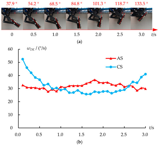
Figure 10.
Resultant test outcomes: (a) angle results; (b) angular velocity results.
3.3. Comparison Test of Spraying with CS and AS
To evaluate the effectiveness of the active control method introduced in this research for improving the uniformity of spraying, a comparative test was conducted involving spraying operations. In this test, water was used in place of the spray mixture, and water-sensitive paper (WSP) was strategically positioned on the top, sides, and bottom of the crops. Upon completion of the test, immediate scanning was performed, and the droplet coverage rate was quantified using ImageJ software 1.38x. The results pertaining to the WSP and the coverage rate after testing are presented in Figure 11.

Figure 11.
Spraying test results of CS and AS.
The data indicate that for CS, the sideways spray coverage rate of crops is significantly greater than that of the upward and downward positions, exhibiting a range of 18.05% across the three orientations. This trend is similar to the results obtained in the experiments of reference [15]. The specific coverage rates are 66.78% for the top layer, 74.39% for the middle layer, and 71.72% for the substratum. The key difference is that reference [15] employed fixed-angle spraying on the sides of the crops, where the coverage rate at various positions primarily depends on the diffusion of the droplets. In this study, the discrepancy can primarily be attributed to the uneven angular velocity at the output end of the linkage mechanism. As illustrated in Figure 4, the pattern of variation in ωDE initially decreases before subsequently increasing, which extends the duration of spraying on the sides of the crops. Given a constant spraying volume per unit time, the amount of water applied is positively correlated with the duration of spraying. Consequently, the coverage rate of water on the sides is the highest. Furthermore, it can be inferred that the coverage rate on the upward of the crops is marginally greater than that on the downward.
In comparison to the coverage results of CS, AS resulted in a significant reduction in coverage on the sideways of the crops, while simultaneously enhancing coverage on both the upward and downward surfaces. The optimized coverage range for the three positions is 5.52%. Compared to spraying at various angles with a fixed nozzle position [11], the difference in coverage across different positions is 9.15%; this study effectively minimizes the extreme variance in spray distribution. Compared to spraying systems equipped with visual and other sensors, the elimination of various sensor configurations [7] and the simplification of motor control complexity due to multiple degrees of freedom [13] can significantly improve the control of the mechanism and enhance the cost effectiveness of the sensors.
However, it is important to note that the coverage on the upward, sideways, and downward surfaces does not achieve complete uniformity. This discrepancy can be attributed to three primary factors: first, following the ejection of droplets from the nozzle, they must navigate through drift and diffusion to reach the leaf surface. During this transit, the droplets are significantly influenced by gravity, which complicates their adherence to the downward of the leaf, thereby resulting in a diminished coverage rate on that surface. Second, despite achieving a correlation coefficient of 0.99 in the curve-fitting process, minor discrepancies persist, particularly in proximity to the initial point. These discrepancies contribute to slight variations in the final angular velocity of the linkage movement. Third, the motion trajectory of the output end of the linkage mechanism developed in this study is characterized by a complex composite motion that combines both parallel and circular movements, rather than a straightforward circular motion. Consequently, when the output linkage operates at a constant angular velocity, the actual distribution density of the liquid diffusion is not entirely uniform.
4. Conclusions and Further Work
This study investigates the variable speed characteristics at the output end of a linkage mechanism and introduces an active control strategy. The proposed method involves dynamically adjusting the control equations governing the input variables to facilitate uniform motion at the output end. Utilizing a multi-link mechanism sprayer as a case study, the research formulates a fitting equation that relates the input and output variables within the multi-link mechanisms through a process of vector equation establishment and implicit function manifestation. The equation is subsequently solved using the MATLAB Simulink module, resulting in an analytical expression for the input variables that maintains a stable angular velocity of the output link within a specific linkage mechanism. Dynamic analysis conducted with Adams software revealed that the stability of the AS curve is significantly enhanced compared to the CS curve, thereby substantiating the efficacy of the methodologies employed in this research.
The findings from the dynamic analysis of the linkage mechanism, conducted using a testing prototype, reveal that within a single operational cycle of 3 s (equivalent to an angular velocity of ωDE = 32.7°/s), the observed angular velocity profiles for both the CS and the AS align closely with the analytical predictions. Specifically, the angular velocity of the CS ranges from 25.8°/s to 52.5°/s, while the angular velocity of the AS exhibits minor fluctuations within a narrow band of 27.8°/s to 36.7°/s. This observation indicates that the speed-regulated linkage mechanism effectively contributes to the stabilization of the output angular velocity. Therefore, these results substantiate the feasibility of employing the proposed active control method based on the linkage mechanism in practical applications.
From the perspective of actual spraying efficacy, the operational stability of the AS significantly surpasses that of the CS. The variability in the spraying coverage rate across the upward, sideways, and downward of the leaves has been reduced from 18.05% to 5.52%. However, it is important to note that the coverage across the three positions of the AS nozzle is not entirely uniform. Specifically, the coverage on the sideways of the leaf is comparatively greater, while the coverage on the underside is relatively lesser. This variation can be attributed to the combined effects of gravitational droplet diffusion and the complex motion dynamics of the linkage mechanism. Therefore, for the multi-link mechanism sprayer proposed in this study, maintaining a constant angular velocity at the output end can significantly improve the uniformity of spraying; however, this approach does not represent the optimal solution. The ideal angular velocity–time profile should be determined based on the distribution density of the spray mixture solution diffusion, which will guide the optimization of the input variable curve. More generally, the methodology presented in this study is applicable to any linkage mechanism where there exists a unique correspondence between input and output variables. Furthermore, in specific scenarios where the output variable must conform to a particular dynamic equation, the proposed method remains applicable, provided it aligns with the adjustment of the input parameters of the Simulink solving model. This approach also outlines the direction for the future optimization of multi-link spraying machines.
Author Contributions
Conceptualization, N.S. and Y.Y.; methodology, H.L. and N.S.; software, H.H. and J.Y.; validation, Z.C. and T.X.; writing—original draft preparation, N.S. and H.L.; writing—review and editing, N.S. and Y.Y.; project administration, N.S. and H.L. All authors have read and agreed to the published version of the manuscript.
Funding
This research was funded by the National Natural Science Foundation of China (Grant No. 32201673), the China Postdoctoral Science Foundation (Grant No. 2023M741436), the Natural Science Foundation of the Jiangsu Higher Education Institutions of China (Grant No. 23KJB630001), the Science and Technology Plan Project of Changzhou (Grant No. CQ20220082).
Institutional Review Board Statement
Not applicable.
Informed Consent Statement
Not applicable.
Data Availability Statement
The raw data supporting the conclusions of this article will be made available by the authors on request.
Conflicts of Interest
The authors declare no conflicts of interest.
References
- Cantelli, L.; Bonaccorso, F.; Longo, D.; Melita, C.D.; Schillaci, G.; Muscato, G. A small versatile electrical robot for autonomous spraying in agriculture. AgriEngineering 2019, 1, 391–402. [Google Scholar] [CrossRef]
- Meshram, A.T.; Vanalkar, A.V.; Kalambe, K.B.; Badar, A.M. Pesticide spraying robot for precision agriculture: A categorical literature review and future trends. J. Field Robot. 2022, 39, 153–171. [Google Scholar] [CrossRef]
- Abbas, I.; Liu, J.; Faheem, M.; Noor, R.S.; Shaikh, S.A.; Solangi, K.A.; Raza, S.M. Different sensor based intelligent spraying systems in Agriculture. Sens. Actuators A Phys. 2020, 316, 112265. [Google Scholar] [CrossRef]
- Zanin, A.R.A.; Neves, D.C.; Teodoro, L.P.R.; Silva Júnior, C.A.; Silva, S.P.; Teodoro, P.E.; Baio, F.H.R. Reduction of pesticide application via real-time precision spraying. Sci. Rep. 2022, 12, 5638. [Google Scholar] [CrossRef] [PubMed]
- Amaya, K.; Bayat, A. Innovating an electrostatic charging unit with an insulated induction electrode for air-assisted orchard sprayers. Crop Prot. 2024, 181, 106701. [Google Scholar] [CrossRef]
- Wei, Z.; Li, R.; Xue, X.; Sun, Y.; Zhang, S.; Li, Q.; Chang, C.; Zhang, Z.; Sun, Y.; Dou, Q. Research status, methods and prospects of air-assisted spray technology. Agronomy 2023, 13, 1407. [Google Scholar] [CrossRef]
- Hussain, N.; Farooque, A.A.; Schumann, A.W.; McKenzie-Gopsill, A.; Esau, T.; Abbas, F.; Acharya, B.; Zaman, Q. Design and development of a smart variable rate sprayer using deep learning. Remote Sens. 2020, 12, 4091. [Google Scholar] [CrossRef]
- Cui, L.F.; Xue, X.Y.; Ding, S.M.; Le, F.X. Development of a DSP-based electronic control system for the active spray boom suspension. Comput. Electron. Agric. 2019, 166, 105024. [Google Scholar] [CrossRef]
- Li, J.Y.; Nie, Z.Y.; Chen, Y.F.; Ge, D.Q.; Li, M.Q. Development of boom posture adjustment and control system for wide spray boom. Agriculture 2023, 13, 2162. [Google Scholar] [CrossRef]
- Appah, S.; Wang, P.; Ou, M.; Gong, C.; Jia, W. Review of electrostatic system parameters, charged droplets characteristics and substrate impact behavior from pesticides spraying. Int. J. Agric. Biol. Eng. 2019, 12, 1–9. [Google Scholar] [CrossRef]
- Dai, S.Q.; Ou, M.X.; Du, W.T.; Yang, X.J.; Dong, X.; Jiang, L.; Zhang, T.; Ding, S.M.; Jia, W.D. Effects of sprayer speed, spray distance, and nozzle arrangement angle on low-flow air-assisted spray deposition. Front. Plant Sci. 2023, 14, 1184244. [Google Scholar] [CrossRef] [PubMed]
- Alam, M.; Alam, M.S.; Roman, M.; Tufail, M.; Khan, M.U.; Khan, M.T. Real-time machine-learning based crop/weed detection and classification for variable-rate spraying in precision agriculture. In Proceedings of the 2020 7th international conference on electrical and electronics engineering (ICEEE), Antalya, Turkey, 14–16 April 2020; pp. 273–280. [Google Scholar]
- Hejazipoor, H.; Massah, J.; Soryani, M.; Vakilian, K.A.; Chegini, G. An intelligent spraying robot based on plant bulk volume. Comput. Electron. Agric. 2021, 180, 105859. [Google Scholar] [CrossRef]
- Liu, X.M.; Li, Y.; Li, M.; Yuan, J.; Fang, Q.Z.; Hou, J.L. Design and test of smart-targeting spraying system on boom sprayer. Trans. Chin. Soc. Agric. Mach. 2016, 47, 37–44. [Google Scholar]
- Luo, Y.H.; Huang, D.F.; Jiang, P.; Xiang, S.L.; Liu, J.F.; Xu, M.Z.; Shi, Y.X. Design and experimental testing of an overhead rail automatic variable-distance targeted spray system for solar greenhouses. Agriculture 2023, 13, 1853. [Google Scholar] [CrossRef]
- Chen, Z.H.; Wang, S.K.; Liu, Q.; Wang, J.Z. Development of sheet palletizing manipulator based on multi-link mechanism. Res. Sq. 2020. [Google Scholar]
- Wei, G.W.; Dai, J.S. A spatial eight-bar linkage and its association with the deployable platonic mechanisms. J. Mech. Robot. 2014, 6, 021010. [Google Scholar] [CrossRef]
- Zhang, Y.H.; Zhang, L.F.; Wang, W.; Li, Y.M.; Zhang, Q.W. Design and implementation of a two-wheel and hopping robot with a linkage mechanism. IEEE Access 2018, 6, 42422–42430. [Google Scholar] [CrossRef]
- Kim, J.W.; Seo, T.; Kim, J. A new design methodology for four-bar linkage mechanisms based on derivations of coupler curve. Mech. Mach. Theory 2016, 100, 138–154. [Google Scholar] [CrossRef]
- Lin, H.K.; Tekes, A.; Tekes, C. Design, development and modelling of single actuated, compliant and symmetrical multilink hopping mechanism. J. Mech. Sci. Technol. 2020, 34, 555–563. [Google Scholar] [CrossRef]
- Huang, T.C.; Youm, Y. Exact displacement analysis of four-link spatial mechanisms by the direction cosine matrix method. J. Appl. Mech. 1984, 51, 921–928. [Google Scholar] [CrossRef]
- Liu, Y.W.; Wang, H.G.; Li, B.; Zhou, W.J. An optimal method to determine the parameters of anthropomorphic finger based on four-link mechanism. In Proceedings of the 2008 2nd IEEE RAS & EMBS International Conference on Biomedical Robotics and Biomechatronics, Scottsdale, AZ, USA, 19–22 October 2008; IEEE: Piscataway, NJ, USA; pp. 842–847. [Google Scholar]
- Martini, A.; Troncossi, M.; Carricato, M.; Rivola, A. Elastodynamic behavior of balanced closed-loop mechanisms: Numerical analysis of a four-bar linkage. Meccanica 2014, 49, 601–614. [Google Scholar] [CrossRef]
- Muralidharan, V.; Bose, A.; Chatra, K.; Bandyopadhyay, S. Methods for dimensional design of parallel manipulators for optimal dynamic performance over a given safe working zone. Mech. Mach. Theory 2020, 147, 103721. [Google Scholar] [CrossRef]
- Lee, S.; Kim, J.; Kang, N. Deep generative model-based synthesis framework of four-bar linkage mechanisms with target conditions. J. Comput. Des. Eng. 2024, 11, 318–332. [Google Scholar] [CrossRef]
- Chen, H.C.; Liu, T.K.; Huang, I.M.; Chou, J.H. Multiobjective synthesis of six-bar mechanisms under manufacturing and collision-free constraints. IEEE Comput. Intell. Mag. 2012, 7, 36–48. [Google Scholar] [CrossRef]
- Allmendinger, A.; Spaeth, M.; Saile, M.; Peteinatos, G.G.; Gerhards, R. Precision chemical weed management strategies: A review and a design of a new CNN-based modular spot sprayer. Agronomy 2022, 12, 1620. [Google Scholar] [CrossRef]
- Shi, N.Y.; Chen, Z.; Li, H.; Hua, H.L.; Xu, T.; Ye, J.H. Development and assessment of a novel single-drive variable angle spraying machine. Sci. Rep. 2024, 14, 31264. [Google Scholar] [CrossRef] [PubMed]
- Sinir, B.G. Derivation of governing equations by using vector approach and comparison of analytical solutions of post-buckling behaviors of transverse functionally graded shear deformable beam theories. Arab. J. Sci. Eng. 2023, 48, 4971–4990. [Google Scholar] [CrossRef]
- Corduneanu, E. Expressions of euler angles as functions of the directional cosines of three-orthogonal axes in rigid body kinematics-II. Bull. Polytech. Inst. Iași. Mach. Constr. Sect. 2021, 67, 17–24. [Google Scholar] [CrossRef]
- Wang, W.J. The explicit expression of axis and angle of a rotation matrix. Coll. Math. J. 2021, 52, 39–44. [Google Scholar] [CrossRef]
- Zhang, W.N.; Zhong, S.; Xia, Y.; Xu, D.W. Air vehicle’s attitude control system based on virtual instrument. In Proceedings of the 2007 8th International Conference on Electronic Measurement and Instruments, Xi’an, China, 16–18 August 2007; pp. 3–74. [Google Scholar]
- Ponomarev, A.; Hofmann, J.; Groll, L. Characteristics-based Simulink implementation of first-order quasilinear partial differential equations. In Proceedings of the 10th International Conference on Simulation and Modeling Methodologies, Online, 8–10 July 2020; Volume 1907, p. 13419. [Google Scholar]
- Sánchez-Hermosilla, J.; Rincón, V.J.; Páez, F.; Agüera, F.; Carvajal, F. Field evaluation of a self-propelled sprayer and effects of the application rate on spray deposition and losses to the ground in greenhouse tomato crops. Pest Manag. Sci. 2011, 67, 942–947. [Google Scholar] [CrossRef] [PubMed]
- Xiao, Y.H.; Wang, J.R.; Yang, J.Q.; Li, J. Dynamic simulation research of adaptive support mechanism of pipeline inspection robot based on ADAMS. J. Phys. Conf. Ser. 2023, 2450, 012047. [Google Scholar] [CrossRef]
- Šarga, P.; Hroncová, D.; Rákay, R. The MSC ADAMS/view and simulation of the crank rocker mechanism. Am. J. Mech. Eng. 2015, 3, 161–164. [Google Scholar]
- Shi, N.Y.; Li, H.; Xu, T.; Hua, H.L.; Ye, J.H.; Chen, Z. Design, analysis, and optimization testing of a novel modular walking device for pipeline robots. Machines 2024, 12, 718. [Google Scholar] [CrossRef]
- Flores-Campos, J.A.; Perrusquía, A.; Hernández-Gómez, L.H.; González, N.; Armenta-Molina, A. Constant speed control of slider-crank mechanisms: A joint-task space hybrid control approach. IEEE Access 2021, 9, 65676–65687. [Google Scholar] [CrossRef]
Disclaimer/Publisher’s Note: The statements, opinions and data contained in all publications are solely those of the individual author(s) and contributor(s) and not of MDPI and/or the editor(s). MDPI and/or the editor(s) disclaim responsibility for any injury to people or property resulting from any ideas, methods, instructions or products referred to in the content. |
© 2025 by the authors. Licensee MDPI, Basel, Switzerland. This article is an open access article distributed under the terms and conditions of the Creative Commons Attribution (CC BY) license (https://creativecommons.org/licenses/by/4.0/).

