1. Introduction
The rapid growth of e-commerce in a globalized market has driven companies to develop increasingly efficient logistics and packaging systems capable of supporting high throughput while maintaining competitive costs. Automated packaging machines must not only protect products from mechanical impacts, humidity, and chemical exposure but also meet strict economic and environmental requirements. By minimizing package volume and weight, particularly critical for air transportation, these machines reduce shipping and storage costs and contribute to sustainability through lower CO
2 emissions and material waste (Blinge [
1]).
Within this context, the CMC Carton Wrap (CW),
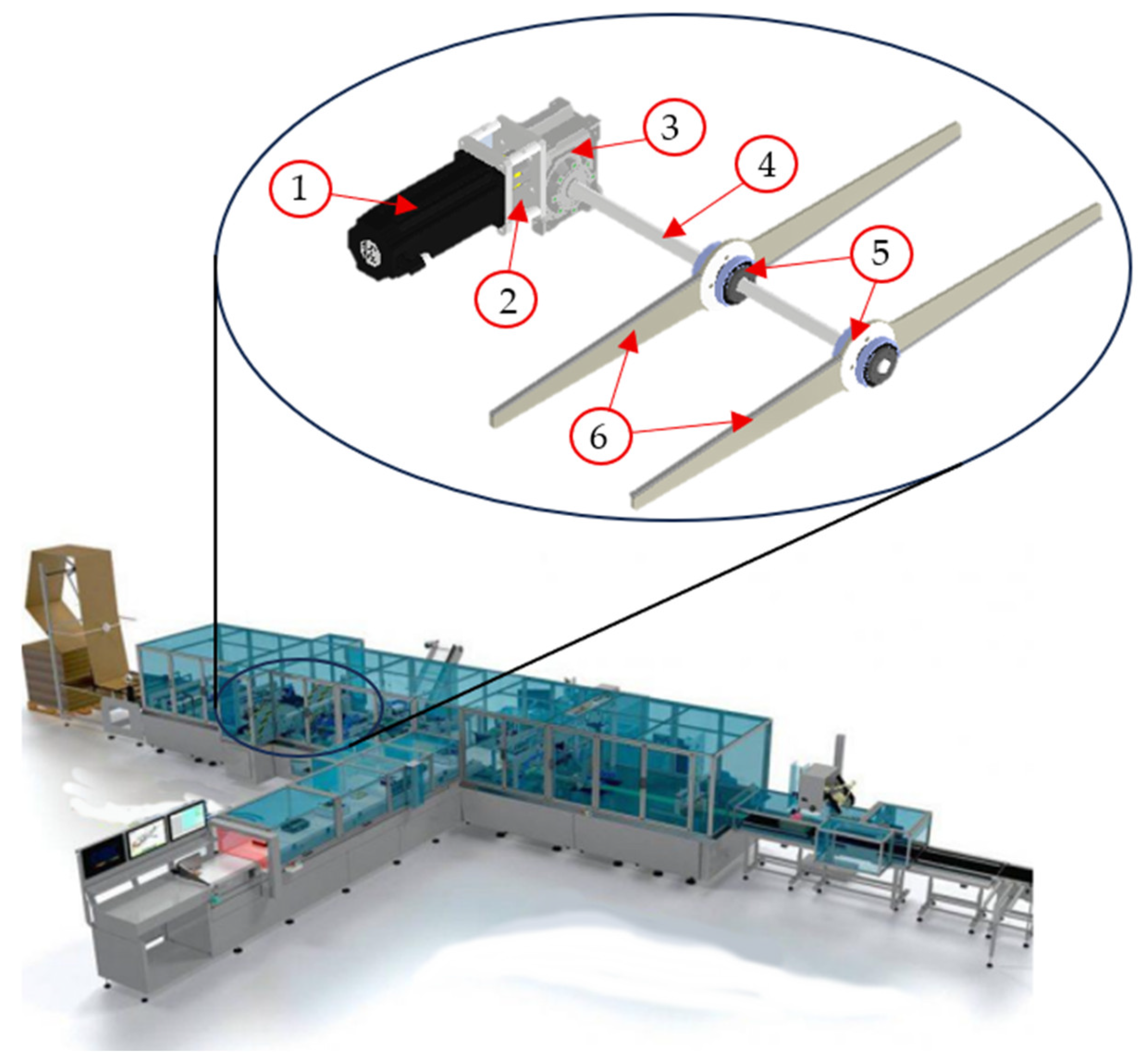
Figure 1, represents a state-of-the-art automatic packaging solution. The system dynamically measures product dimensions and forms customized boxes from continuous corrugated cardboard sheets, achieving production rates of up to 15 boxes per minute. Such high throughput inevitably imposes significant dynamic loads on the mechanical subsystems, making robust design strategies essential to ensure precision, reliability, and durability under high-frequency excitations.
A critical subsystem is the die-cutting unit, which consists of a rotating shaft carrying a pair of rolling blades. The blades, capable of translating along the shaft axis, are actuated by a servomotor to create grooves required for subsequent folding and sealing operations. High angular velocities are necessary to achieve clean cuts without tearing the material. Under these conditions, the system becomes susceptible to torsional vibrations, a primary cause of rotor degradation, including keyway wear, oil leakage, and reduced cutting quality over extended operation (Muszynska et al. [
2]).
Several studies have investigated the torsional dynamics of rotating machinery. Classical modal testing has been applied to identify rotor natural frequencies (Wang et al. [
3], Fairbairn et al. [
4]), while Operational Modal Analysis (OMA) has been employed for turbomachinery and centrifugal compressors (Carden and Lindblad [
5], Guglielmo et al. [
6]). More recently, torsional eigenfrequency monitoring has been used for predictive maintenance, and approaches based on neural networks or harmonic analysis have demonstrated enhanced sensitivity for early fault detection (Van Wyk and Hoffman [
7], Hougaard et al. [
8]).
Moreover, concepts from vehicle suspension systems provide valuable insights for vibration mitigation in rotating machinery. Research on semi-active inertial suspensions has shown that the combination of inertial elements with appropriately tuned control strategies can significantly enhance vibration isolation across a wide frequency range, improving both ride comfort and structural response (Yang et al. [
9]). This indicates that inertial mechanisms, when properly designed, can be highly effective for broad-spectrum vibration reduction in industrial applications without requiring continuous external energy input.
Various strategies have been proposed to mitigate undesired vibrations. Radial dampers have been successfully applied in hydropower units to reduce shaft resonance (Gustavsson et al. [
10]), while variable friction dampers have proven effective in structural systems (Ferrotto et al. [
11]). Tuned mass dampers (TMDs), optimized through bio-inspired algorithms, have also shown potential in attenuating oscillations in high-rise structures (Vanshaj et al. [
12]). Recent advancements in vibration control have introduced novel devices that integrate inertial mechanisms to improve damping efficiency. For instance, the Clutching Inertia System (CIS) introduces a rotational inertia component capable of adaptively engaging to dissipate vibrational energy, particularly when coupled with friction damping elements that enhance its active duration and control precision (Bai et al. [
13]). Similarly, visco-hyperelastic inertial dampers have demonstrated high adaptability across a wide frequency range and have proven particularly effective in suppressing multi-modal resonances in continuous systems such as pipelines (Jing et al. [
14]).
A significant evolution of classical damping systems is represented by the Tuned Mass Damper Inerter (TMDI), which combines the conventional TMD with an inertial device producing resistance proportional to relative acceleration (Kang et al. [
15]). The TMDI has gained attention for its dual functionality: not only does it suppress structural vibrations effectively, but it can also enable energy harvesting when coupled with electromagnetic devices (EM-TMDI), converting vibrational energy into electrical energy. Recent reviews emphasize the wide applicability of these systems in building and bridge engineering, while also identifying challenges such as parameter tuning and cost reduction.
Early studies on active control have also explored active TMDs, in which actuators introduce variable stiffness and damping for optimal performance under dynamic loads (Abdel-Rohman [
16]). With his work, he demonstrated that the optimal tuning of an active TMD depends on the desired control level and on the interaction between the device and the building’s first natural mode. However, such systems require a continuous energy supply, sensors, and advanced controllers, leading to higher complexity and cost, which limits their practical use in compact industrial machinery.
A recent comprehensive literature review of vibration mitigation systems in civil and mechanical engineering (Koutsoloukas et al. [
17]), indicates that, despite the advances in active and hybrid damping technologies, passive systems remain the most widely implemented in real-world applications. In fact, 63% of analyzed case studies refer to passive TMDs, compared to 31% hybrid, 4% active, and only 2% semi-active devices. This dominance is primarily due to their simplicity, robustness, and reliability. Passive dampers dissipate vibrational energy without external power, sensors, or active control, relying on intrinsic mechanisms such as friction, inertia, or elastic energy storage [
18,
19,
20,
21]. Applications range from friction-based damping in sandwich structures (Romberg [
18]), to auxiliary mechanical systems in machining tools (Thomas et al. [
19]), variable inertia clutching devices (Cupp and Wierschem [
20]), and passive balancing cams for engines (Cardoso et al. [
21]). These approaches collectively demonstrate the versatility and effectiveness of passive damping in mitigating torsional vibrations in high-speed mechanical systems. The use of a mass damper represents a promising solution due to its simplicity, robustness, and minimal maintenance requirements.
Given the operating conditions of high-speed packaging machines such as those of CMC CW, where continuous operation, minimal maintenance, and compact integration are required, the adoption of an optimized passive TMD is the most practical and efficient solution. Unlike active or semi-active devices, a passive TMD does not require energy input or complex control architectures, offers low implementation cost, and can be easily tuned to target the dominant torsional mode of the shaft. Moreover, its limited footprint, high reliability, and minimal maintenance make it ideal for industrial environments where downtime must be avoided. For all these reasons, the majority of TMDs implemented in industrial systems employ passive configurations. In this work, the concept is also investigated, developing a device design tailored to a rotor while allowing for a certain degree of adjustability in terms of natural torsional frequency. Accordingly, this study aims to:
model and characterize the torsional dynamics of the CW die-cutting system under operational conditions, integrating experimental modal analysis and multibody simulations;
design, manufacture, and validate the TMD to mitigate resonance peaks, reduce torque oscillations amplitude, and enhance the dynamic behavior of high-speed packaging machinery;
increase the decay rate of at least 20%, in a way that the closed-loop controller will stabilize the rotor more quickly;
introduce a numerical FRF validation criterion based on a reduction ratio of at least 10% of the first three resonance peaks;
propose a methodology and a TMD design that can be adapted to a wide range of existing machines on the market and replicated across different applications.
2. Experimental Characterization of the Die-Cutting System
The die-cutting system under investigation is a complex rotor composed of several interconnected components:
Electric motor (1)
Elastic joint (2)
Gear reducer (3)
Spline shaft (4)
Spline balls (5)
Rolling blades (6)
The operating procedure of the system is relatively straightforward. Once the cardboard reaches the correct position inside the machine, the electric motor is activated, generating angular acceleration of the rotor. The spline shaft transmits the rotational load to the spline balls, which act as recirculating ball guides, enabling torque transfer to the blades. With a length exceeding one meter, the blades constitute the primary source of inertia within the rotor. During each cutting cycle, the blades rotate by 180° around their axes. Shortly after reaching maximum rotational speed, the blades collide with the cardboard while the motor transitions to braking mode.
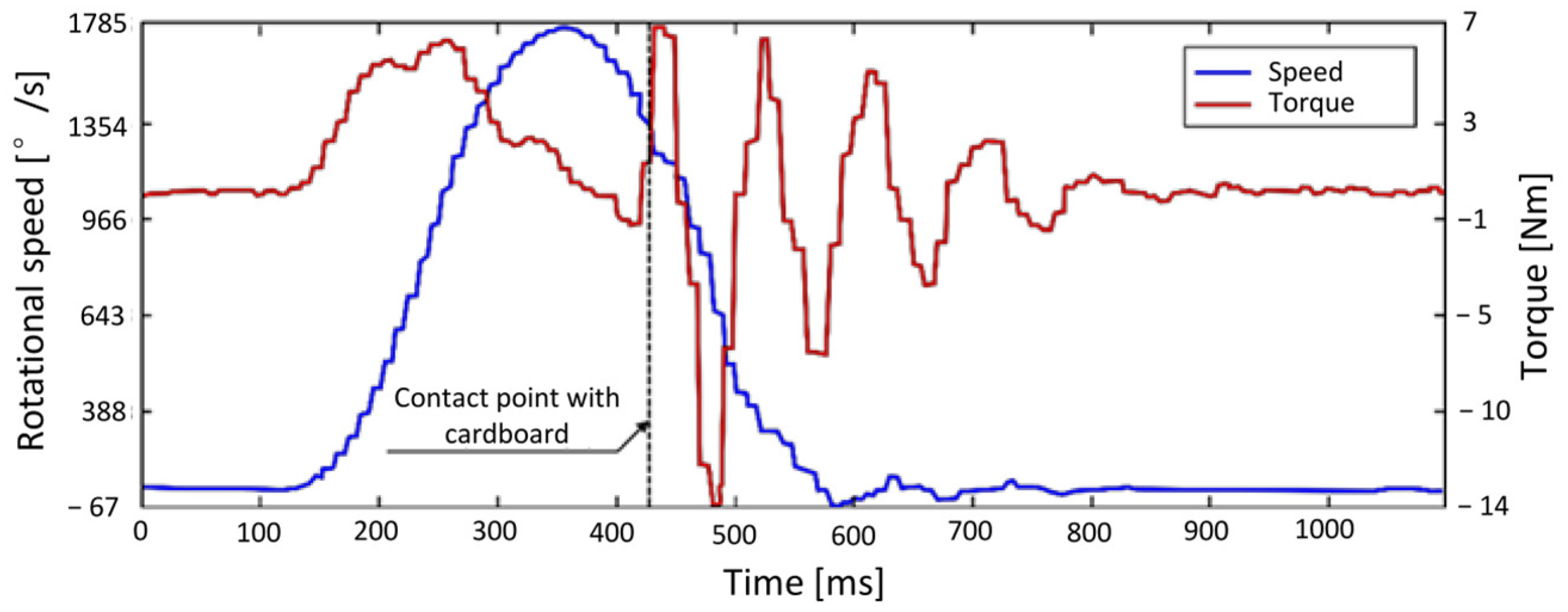
Figure 2 shows the real-time torque produced by the motor and the rotational speed, both recorded during standard operation using load cells and angular position sensors.
Inspection of the torque diagram in
Figure 2 reveals pronounced oscillations beginning at the instant of contact. This behavior was initially attributed to the motor attempting to follow the prescribed motion law. In a closed-loop position and velocity control system, torque is adjusted to track the desired path. Upon impact, a sudden drop in blade rotational speed occurs, prompting the motor to increase torque to compensate. However, this corrective action is overestimated, particularly during braking, resulting in an even larger torque drop. Although the controller stabilizes the oscillations within approximately 0.5 s, neither returning the control parameters nor modifying the contact timing with the cardboard significantly reduces these effects.
It should also be noted that the diagrams in
Figure 2 are influenced by software misconfiguration: the motor was programmed for a 360° rotation, with the transmission ratio of the gear reducer set to 5 instead of the actual 180° rotation and a ratio of 10. This error effectively doubles the rotational speed and halves the oscillation frequency, measured at 11.5 Hz.
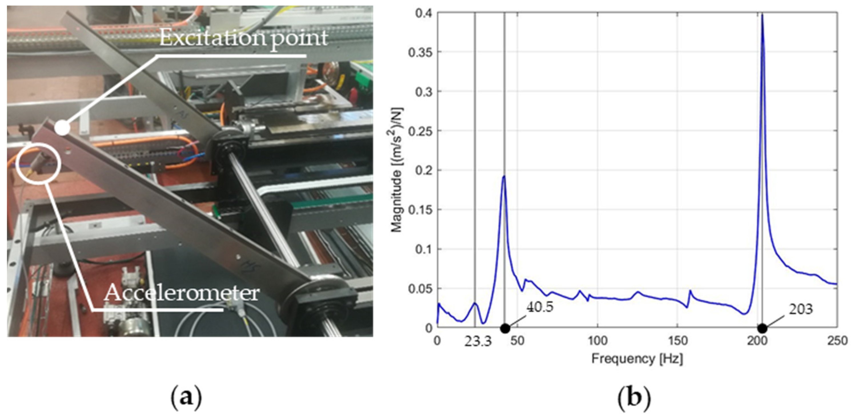
While the controller affects the torque profile post-impact, the possibility that the observed behavior is primarily caused by excitation of a torsional rotor resonance cannot be excluded. To investigate this, an experimental modal analysis was conducted. The typical frequency response function (FRF) test was performed, as shown in
Figure 3a. The structure was excited using an instrumented hammer, while an accelerometer was mounted at the trailing edge of the blade near its tip. Specifications of the sensors employed are reported in
Table 1 and
Table 2.
The complex ratio of the Fourier transforms reveals the dominant frequencies of the system, as shown in
Figure 3b.
Since the dynamic behavior of the rotor depends on the position of the left blade, measurements were performed under three configurations, as summarized in
Table 3. The most energetic frequencies remain similar within a blade spacing range of 148–350 mm. However, when the spacing increases further, only two dominant frequencies are observed.
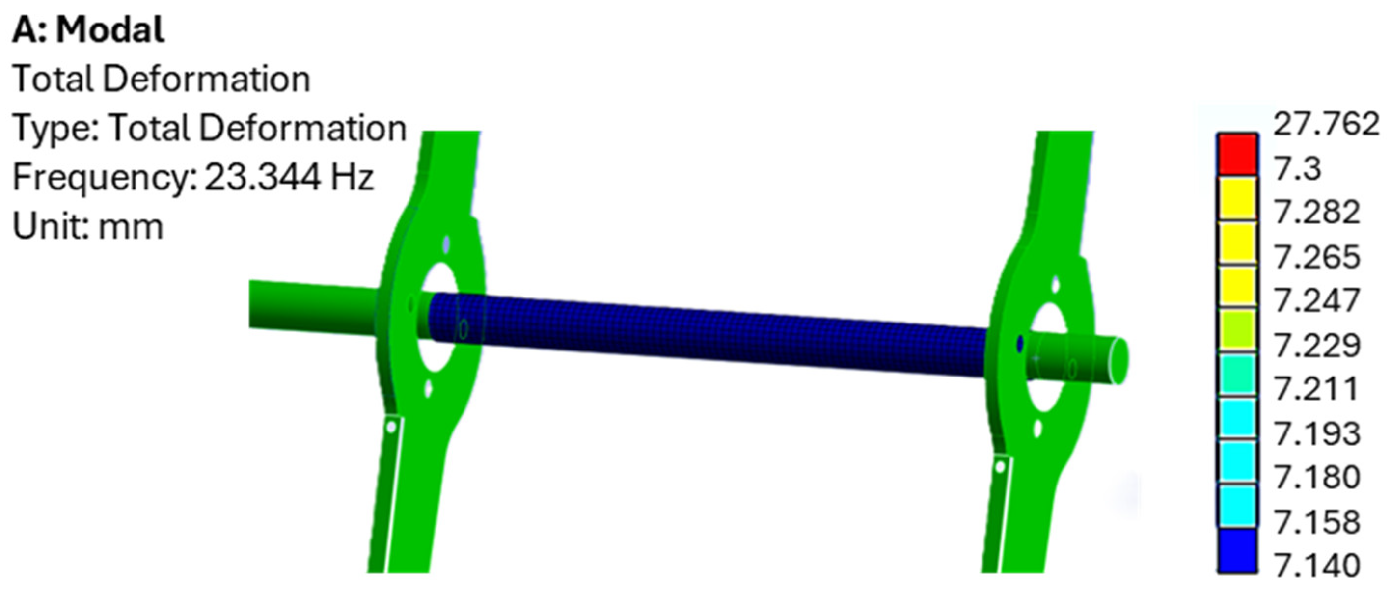
Finite element analysis (FEA) indicates that the third peak, at the highest frequency, corresponds to the first bending resonance of the blade, while the first and second peaks are associated with torsional resonances of the rotor. To validate this interpretation, a multibody analysis was subsequently conducted, as described in the following section.
Figure 4 presents the modal analysis of the blade. The frequency discrepancy with the measured value of
Figure 3b is due to the boundary conditions used in the model, which assumed a fully fixed constraint instead of the four-bolt connection.
3. Dynamic Model of the Die Cutting Machine
The multibody (MBD) model of the rotor was performed using MSC Adams software, version 2023 [
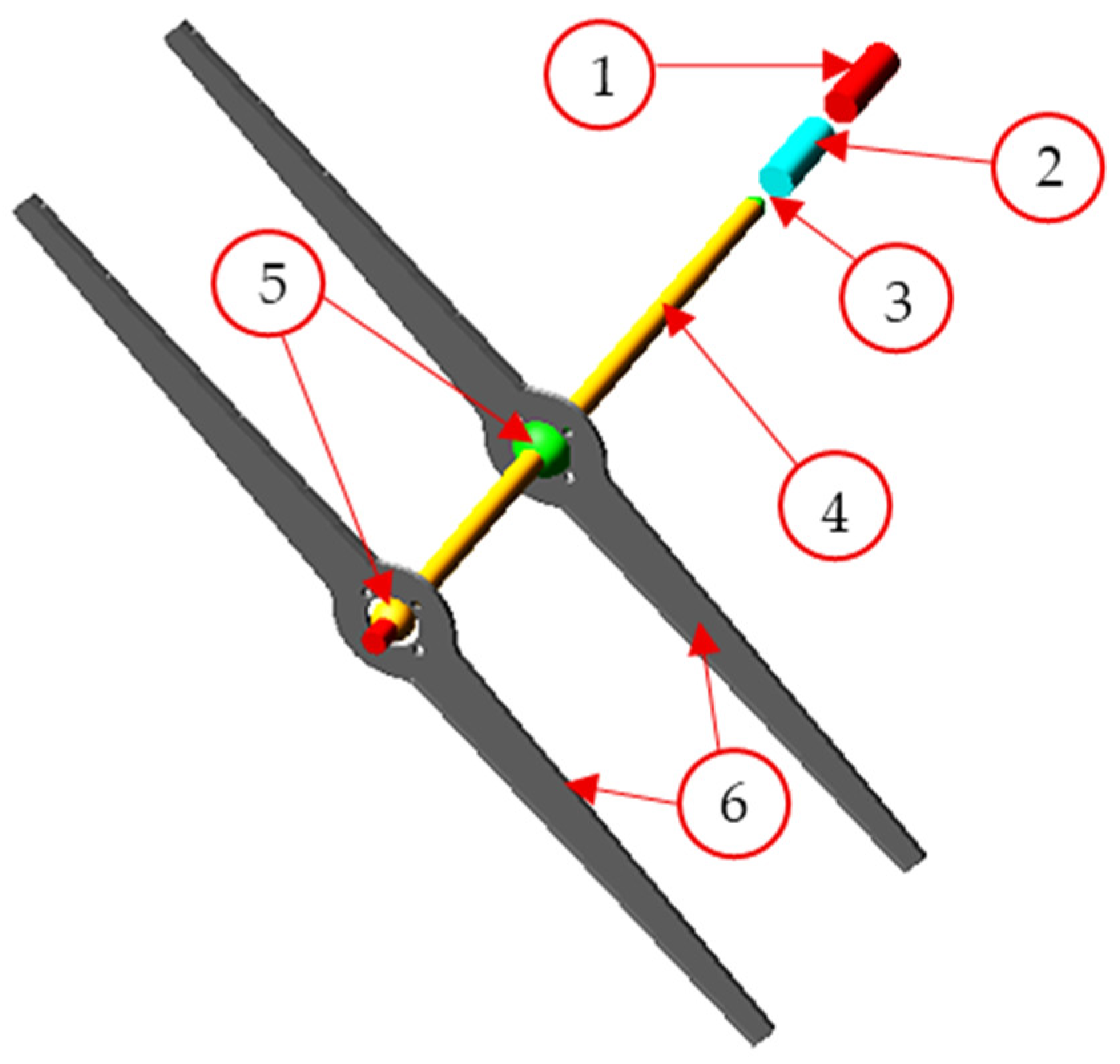
22]. The model was developed with two main objectives: (i) to demonstrate that the experimentally identified frequencies correspond to the torsional eigenfrequencies of the rotor and (ii) to support the design and testing of the TMD capable of attenuating these vibrations. To replicate the actual operating conditions of the machine, all rotor components were explicitly represented in the model, as shown in
Figure 5.
The rotational speed profile from
Figure 2 was replicated in MATLAB R2018a [
23], appropriately scaled, and imported into Adams as a prescribed motion using Akima spline interpolation. The motor (1), using a proportional and derivative controller, calculates the necessary torque to be able to reproduce the real kinematic. Rotational joints are employed to connect components, while a coupler (3) simulates the gear reducer placed between the elastic joint (2) and the shaft (4). This is the only flexible element in the model presented in
Figure 5, and, in terms of stiffness, it is divided into two components: K
1, between the left blade and the gear reducer, and K
3, between the two blades. Dummy spheres and torsional springs (5) replicate the spline balls’ behavior connecting the blades (6) to the shaft. The rotor is supported by four hinges, located close to the motor, the elastic joint, and both dummy spheres. The main uncertainties in this model lie in the magnitude of the impact forces, which simulate collision with the paperboard, and the controller design parameters. Mechanical properties of the elements are summarized in
Table 4.
The system shown in
Figure 5 performs a 180° rotation driven by the motion controller integrated into the electric motor; see
Figure 6. By adjusting the rotational speed profile of
Figure 2 and imposing it as the desired reference curve, ω*, the corresponding torque is applied to the rotor. Note that the control parameters K
p and K
v were assumed, since no information about the actual controller was available. During the simulation, a pair of forces was applied to the blades to reproduce the impact with the paperboard. The magnitude of these forces was computed from the torque jump exhibited inside in a previous work of Morettini et al. [
24].
A frequency response analysis was performed in MSC Adams.
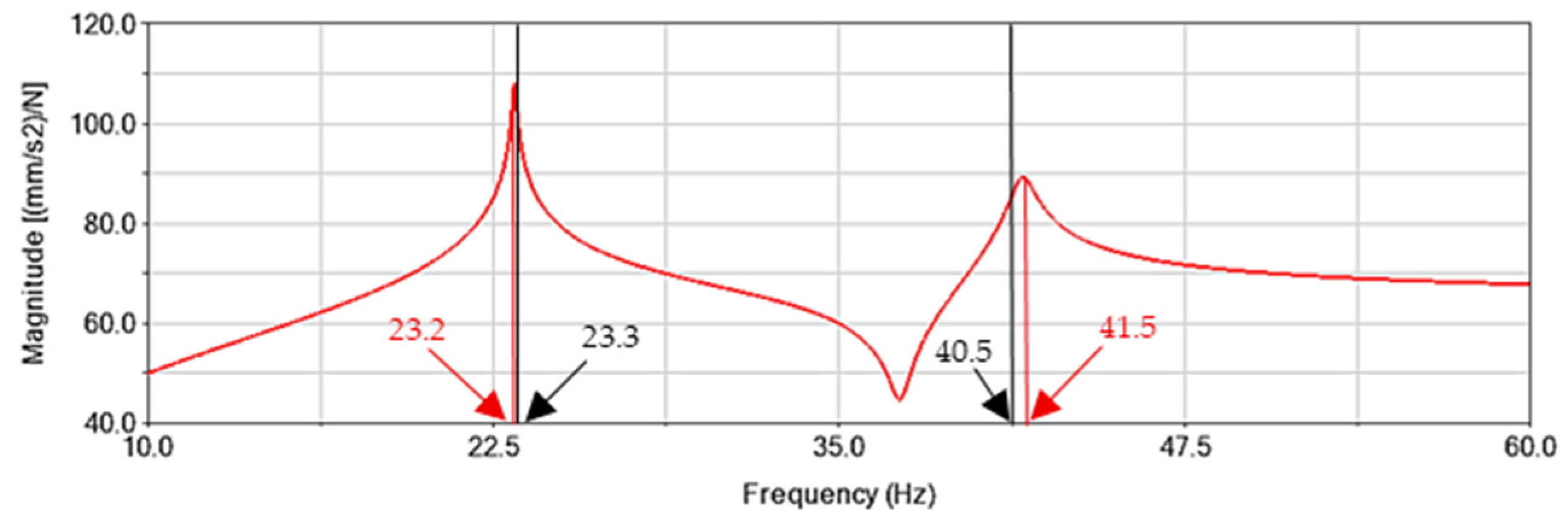
Figure 7 compares the numerical frequency response function (FRF) with the experimental eigenfrequencies for the blade spacing of 350 mm.
The results indicate that the predicted resonance peaks closely match the experimental findings.
Figure 8 further confirms the presence of two torsional resonant frequencies, along with their corresponding mode shapes.
Finally,
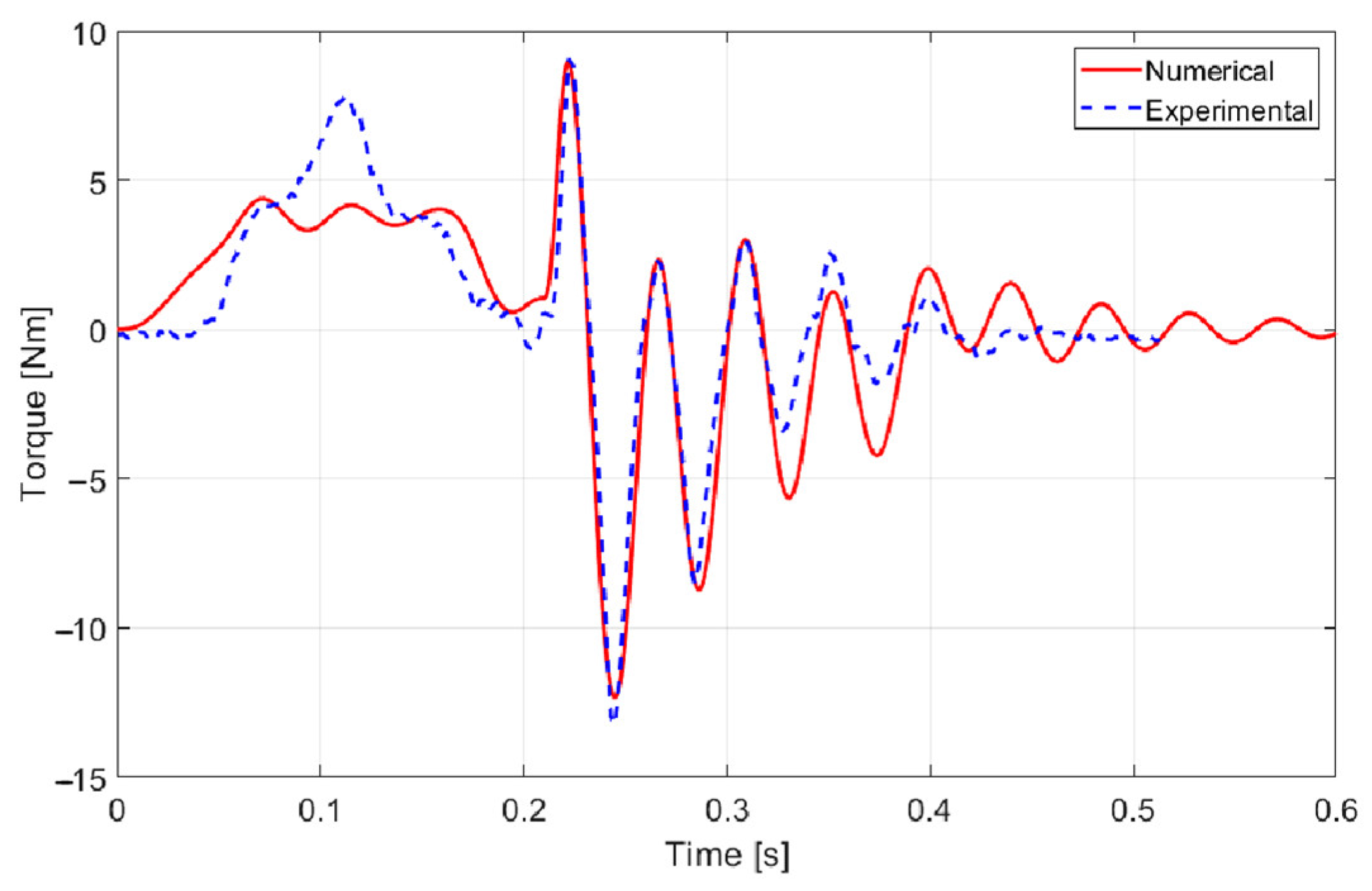
Figure 9 compares simulated and experimental motor torque. Although the exact controller type and parameters are unavailable, the simulation reproduces the experimental trend reasonably well.
The first torsional eigenfrequency of the rotor corresponds exactly to twice the oscillation frequency of the torque observed in
Figure 2. Therefore, the excitation of the first torsional resonance of the die-cutting system is identified as the primary cause of the damaging vibrations, highlighting the need for a damping solution to mitigate its effects.
4. TMD Analytical Theory
Pani et al. [
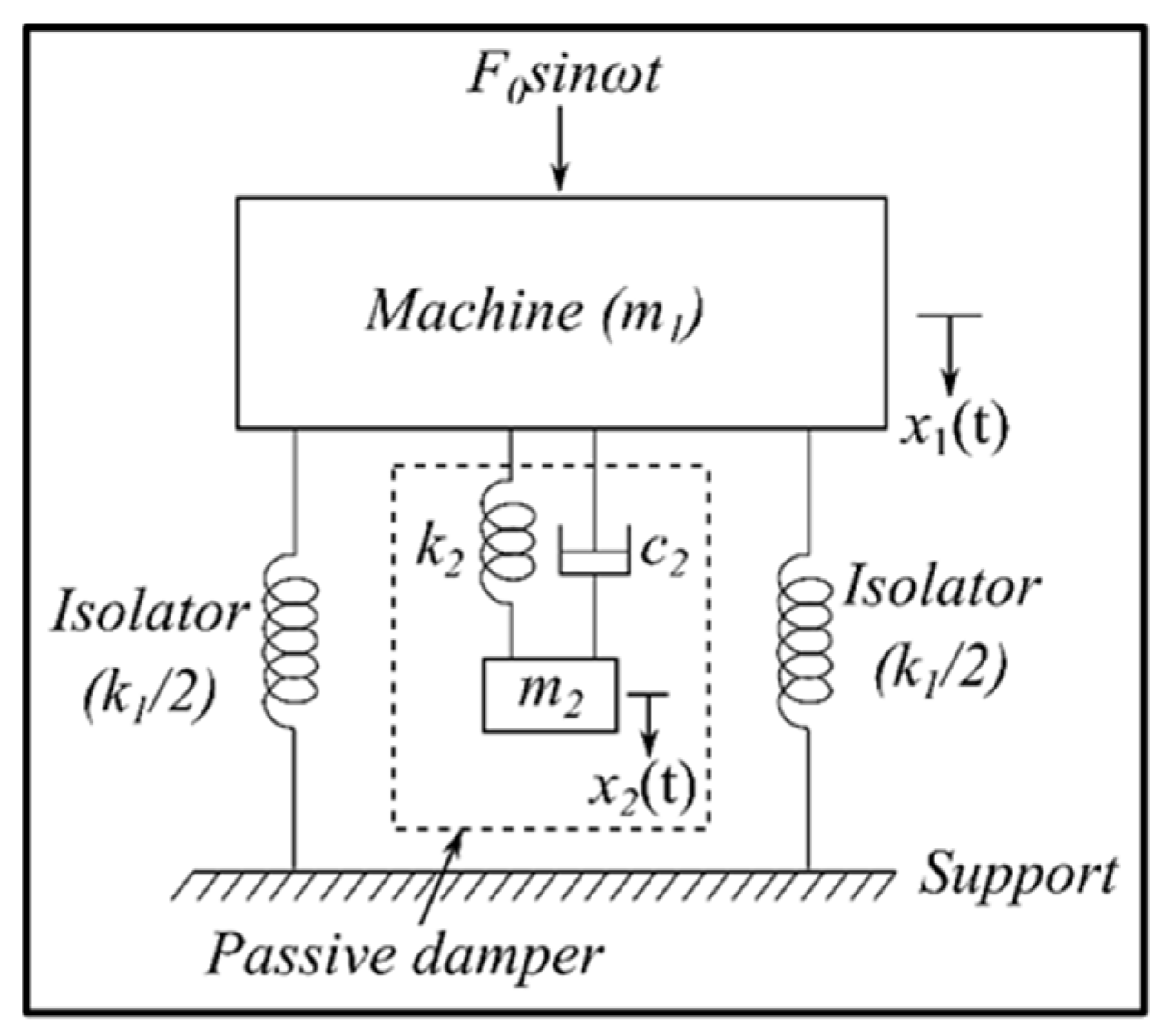
25], working on beam-supported structures, demonstrated the possibility of achieving antiresonance in vibrating systems by adopting a translational tuned mass damper (TMD), as illustrated in
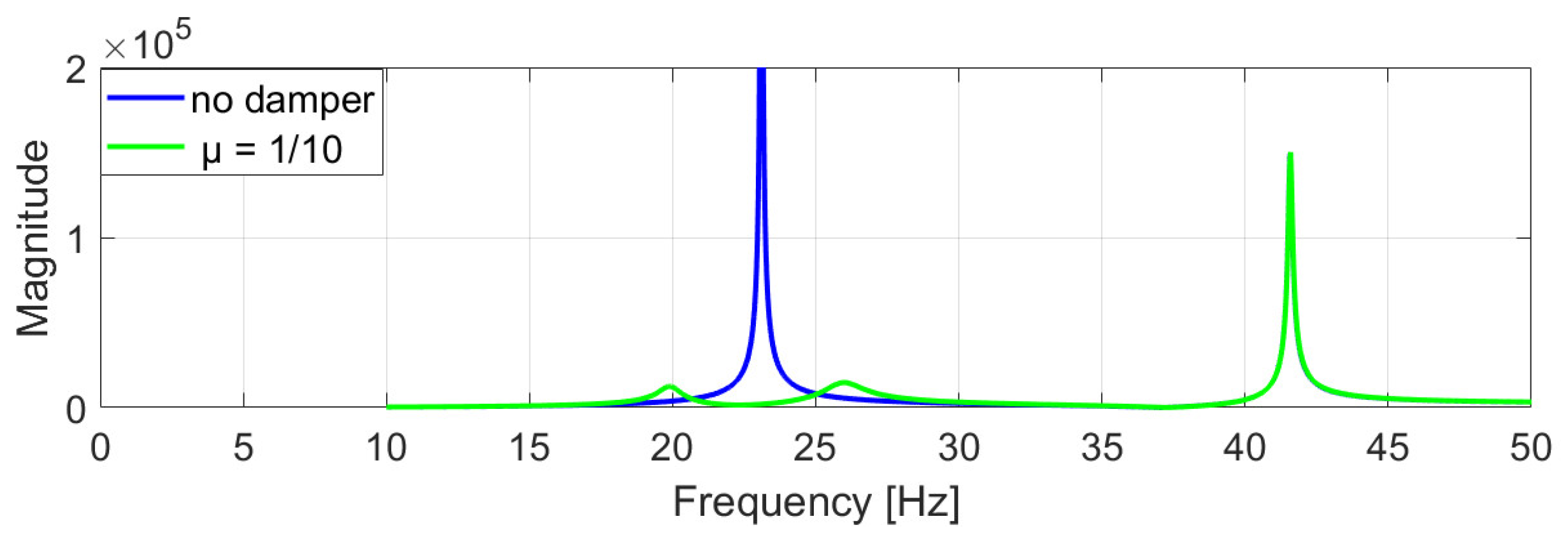
Figure 10. When properly tuned and connected to the system, this auxiliary mass reduces the oscillation amplitude of the primary structure and helps prevent failures. For a rotational single degree-of-freedom (DOF) system equipped with the TMD, the scheme presented in
Figure 8 substitutes masses with inertias, with
that denotes the auxiliary inertia, and
and
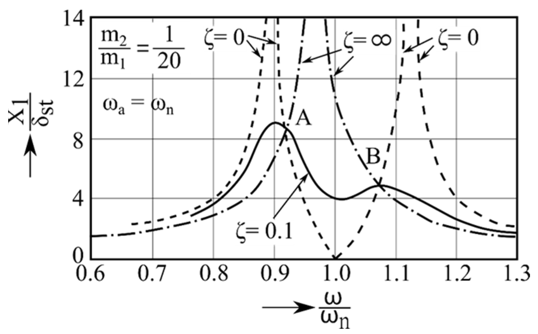
represent the torsional stiffness and damping coefficient of the coupling element, respectively. Integrating the TMD into the machine modifies the original dynamic behavior: the single resonance peak of the undamped system splits into two distinct peaks, as shown in the frequency response function (FRF) of
Figure 11.
To demonstrate this analytically, the equations of motion corresponding to the rotational schematic in
Figure 8 are formulated as:
Assuming that the primary inertia
is subjected to a harmonic moment
, the angular displacements of the inertias can be expressed in harmonic form as
. Substitution leads to the frequency-domain responses:
By introducing the static angular deflection of the system, the normalized vibration amplitude of the primary inertia becomes:
Equation (5) can be plotted with the normalized angular displacement magnitude on the vertical axis and the frequency ratio
on the horizontal axis, as shown in
Figure 11. The results confirm that the properly tuned TMD reduces the amplitude at the original natural frequency, although it introduces two new resonance peaks on either side. Increasing the damping ratio
ζ decreases the magnitude of both peaks.
The intersection points A and B of the undamped and damped FRFs can be determined by first substituting
ζ = 0 and then
ζ→
into Equation (5), leading to:
By replacing the roots
and
of Equation (6) into Equation (5), the coordinates of points A and B are obtained. Maximum efficiency of the TMD is achieved when the ordinates of points A and B are equal, which requires the ratio between the natural frequencies of the system
and the mass ratio
to satisfy the relation:
5. Design Phase of a TMD
5.1. Definition of the Design Parameters
The design of the TMD begins by modelling the physical parameters of this component according to the theory and the machine’s practical limits. In addition, several design conditions must be satisfied:
The first condition derives directly from Equation (7). By substituting the expression of the mass ratio, the ideal inertia of the TMD can be obtained as:
Integrating a new device into the rolling blades poses significant challenges. The first torsional mode of the rotor involves synchronous blade vibrations; consequently, the shaft section between the blades stores negligible elastic energy and behaves as part of the rotor inertia rather than as a spring. In
Figure 12, FEA was conducted to corroborate this concept. As expected, no deformation gradient is present along the shaft axis during the first torsional mode of the rotor. Therefore, the added inertia is located and connected in this section.
Spatial constraints also play a role. To avoid interference with adjacent components, the damper prototype was designed as a cylinder with a width of 30 mm and a radius of 200 mm. From the knowledge of the rotor’s eigenfrequency and by imposing an inertia-to-mass ratio of 0.1, the natural pulsation of the TMD can be calculated.
Using the natural frequency formula of an undamped single-degree-of-freedom system, the required torsional stiffness can then be determined as follows:
The resulting design parameters of the torsional TMD are summarized in
Table 5.
5.2. Numerical Evaluation of TMD Performance
Based on the parameters defined above, a simplified model of the damper was incorporated into the multibody simulation shown in
Figure 5. The cylindrical-shaped mass was positioned on the shaft section between the rolling blades, as previously explained, and connected by means of a torsional spring with the calculated stiffness coefficient,
.
As can be seen from
Figure 13, which presents a comparison of the frequency response analysis, a significant reduction in the first frequency amplitude is obtained.
The response obtained is consistent with the theoretical prediction shown in
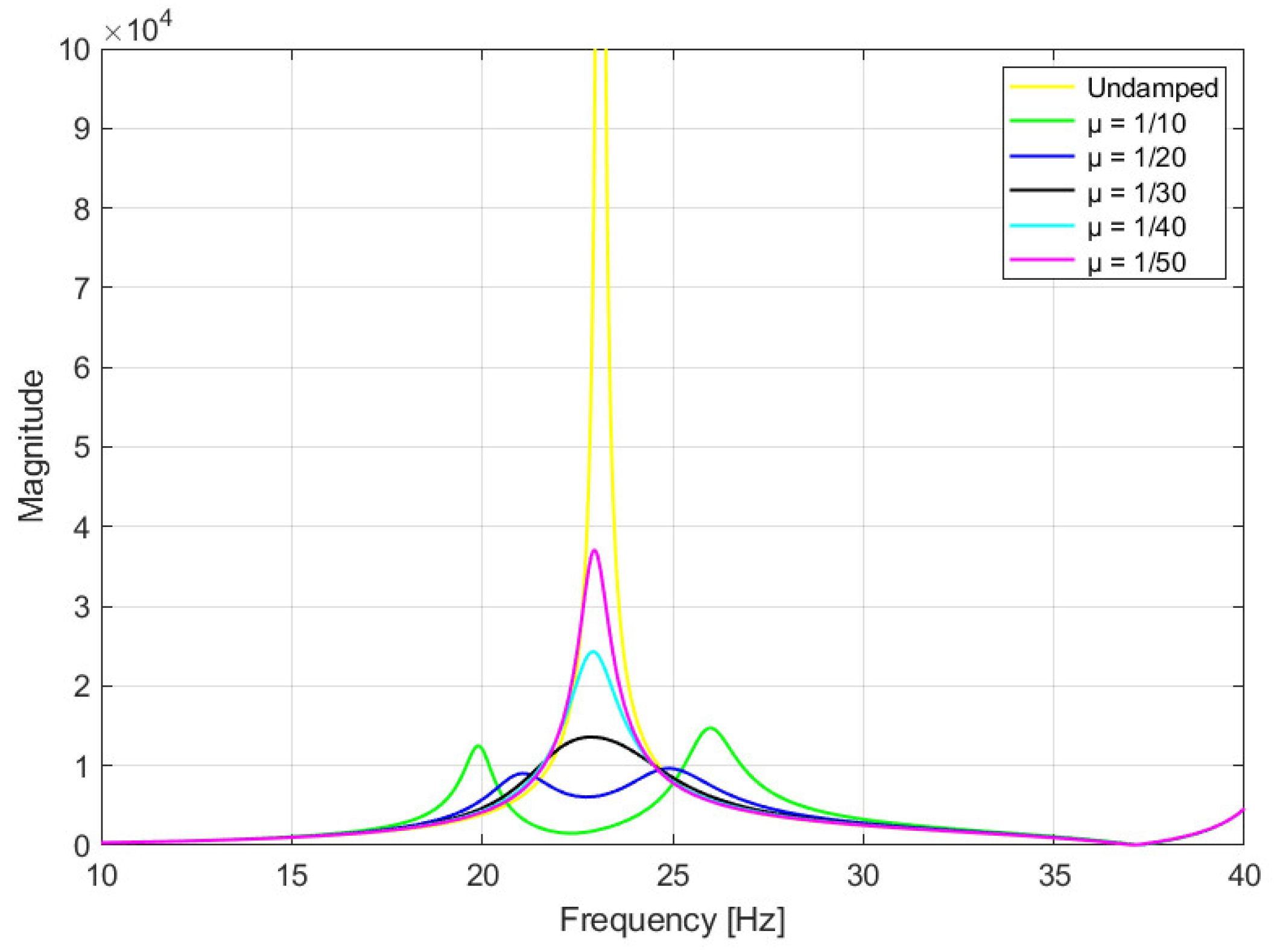
Figure 11. To evaluate the most effective inertia ratio, several scenarios were simulated, as reported in
Figure 14.
Both configurations with
μ = 1/10 and
μ = 1/20 ensure a good result. In general, the most favorable condition is represented by the blue curve in
Figure 14, where the overall magnitude is minimized. However, the green curve exhibits greater antiresonance, which led to its selection as the final design parameter.
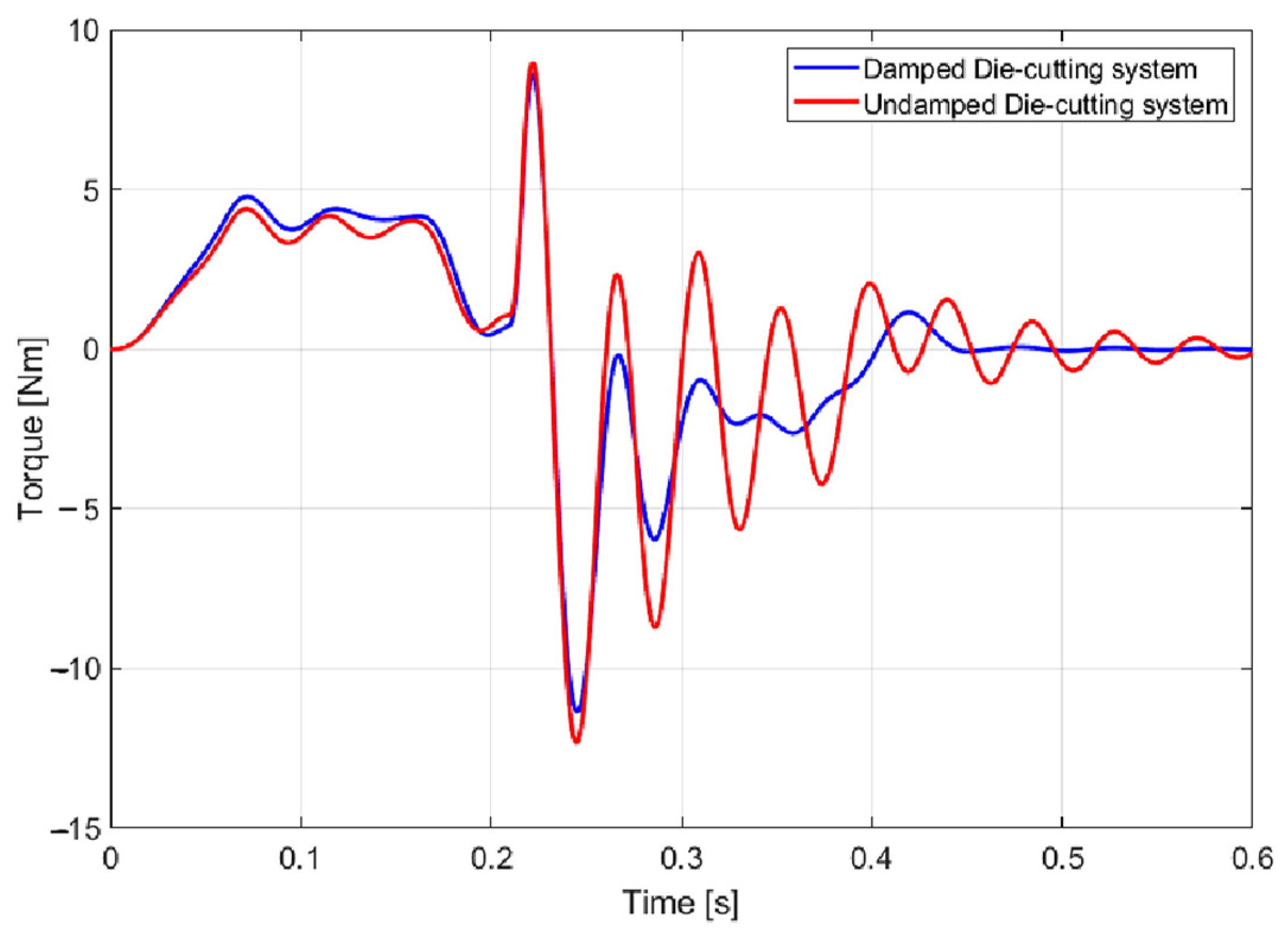
To further confirm the benefits of the TMD adoption,
Figure 15 compares the simulated engine torque with and without the added inertia.
A rapid decrease in oscillation amplitude can be clearly observed. This positive effect strongly reduces the alternating stresses, which are known to play a critical role in fatigue failure mechanisms (Collins [
26]).
5.3. Detailed TMD Design
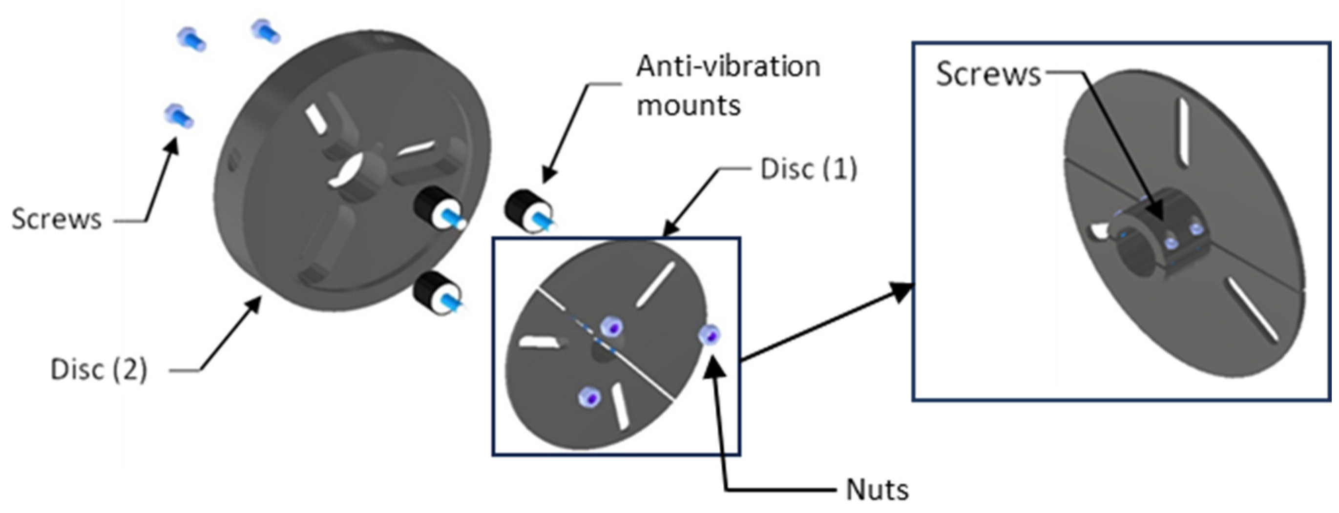
A double-disc configuration was adopted to achieve a compact and robust design. One disc provides shaft keying, while the other delivers the required rotational inertia. Disc (1) is manufactured in two halves and ensures shaft keying through friction when fastened with four screws. Disc (2), also split into two sections for assembly, supplies the necessary inertia. Both discs are machined with slots to accommodate the anti-vibration mounts.
The anti-vibration mounts consist of rubber with a steel core and can be securely bolted to the discs. Their stiffness values and maximum allowable deflections are specified in the manufacturer’s catalogue.
Since, during the torque exchange between discs, the anti-vibration mounts are loaded with a shear stress (
Figure 16), the relation with the torsional stiffness of the TMD is expressed by:
where
is the number of mounts and
is their radial distance from the rotor axis. Once a mount type is selected from the catalogue,
shall be computed to verify that its value falls within the slot limits (30–70 mm).
The structural validation of these elements can be performed considering that their deflection must not exceed the maximum allowable value
specified by the manufacturer. This validation can easily be performed using Equations (11) and (12):
where
is the maximum angular acceleration of the rotor, experimentally obtained and confirmed through multibody analysis and
is the resulting deflection.
The values of the main parameters presented above are listed in
Table 6.
5.4. Keying and Tuning of the TMD
As shown in Equation (12), the torsional stiffness is quadratically dependent on the radial position of the mounts, so small changes in result in significant stiffness variations. This feature allows the TMD to operate within a tunable stiffness range by sliding the mounts along the slots, enabling fine adjustment of its torsional natural frequency to compensate for design uncertainties.
The main source of uncertainty is the mounts’ shear stiffness, which can vary due to manufacturing tolerances and material properties. To determine the actual stiffness, an experimental frequency response test was performed using the TMD with mounts positioned at the design radius. The measured torsional natural frequency differed from the expected value, prompting a finite element analysis (FEA) calibration.
A finite element model of the TMD was developed in ANSYS 2024 R2 to reproduce its dynamic behavior and identify the torsional natural frequency. Each mount was modeled as a bushing element with adjustable shear stiffness , while the total moment of inertia of the moving parts was set equal to the designed value of the physical absorber. The boundary conditions replicated the experimental test setup, with the disc fixed to the shaft.
A modal analysis was first carried out to verify that the fundamental mode corresponded to a pure torsional motion of the TMD. The initial simulation, using the nominal shear stiffness values from the manufacturer, produced a torsional natural frequency lower than the experimental one, indicating that the actual shear stiffness was underestimated. Therefore, was iteratively increased in the model until the simulated torsional natural frequency matched the measured value. This calibration procedure provided an estimate of the true effective stiffness of the mounts, which was then used in subsequent simulations.
Once calibrated, the FEA model was employed to adjust the radial position of the mounts to achieve the target torsional natural frequency required for tuning. The resulting configuration was later implemented in the physical TMD, confirming the validity of the model, as the experimental frequency matched the predicted value within the measurement uncertainty.
The calibrated parameters are summarized in
Table 7.
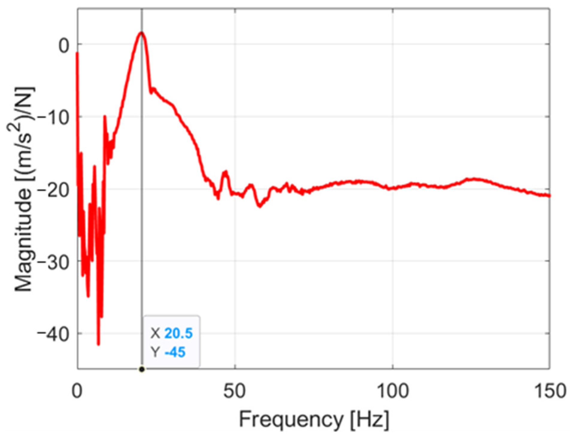
Finally, an experimental test confirmed the tuned torsional resonance frequency of the TMD (
Figure 17).
6. Analysis of the Results
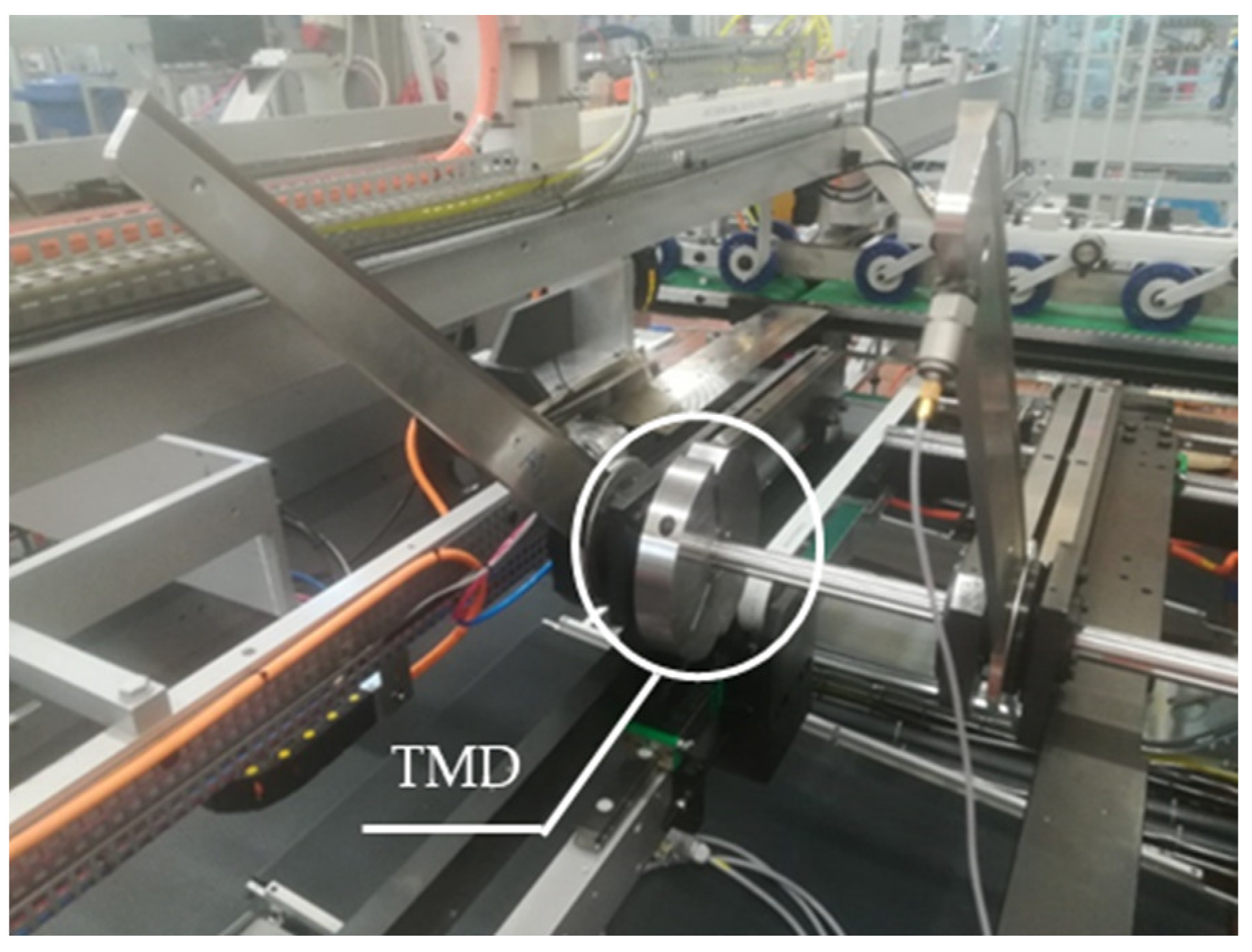
The TMD was installed on the rotor shaft, as shown in
Figure 18. Following installation, a new experimental campaign was conducted to evaluate the improvements introduced by the damper to the rotor dynamics.
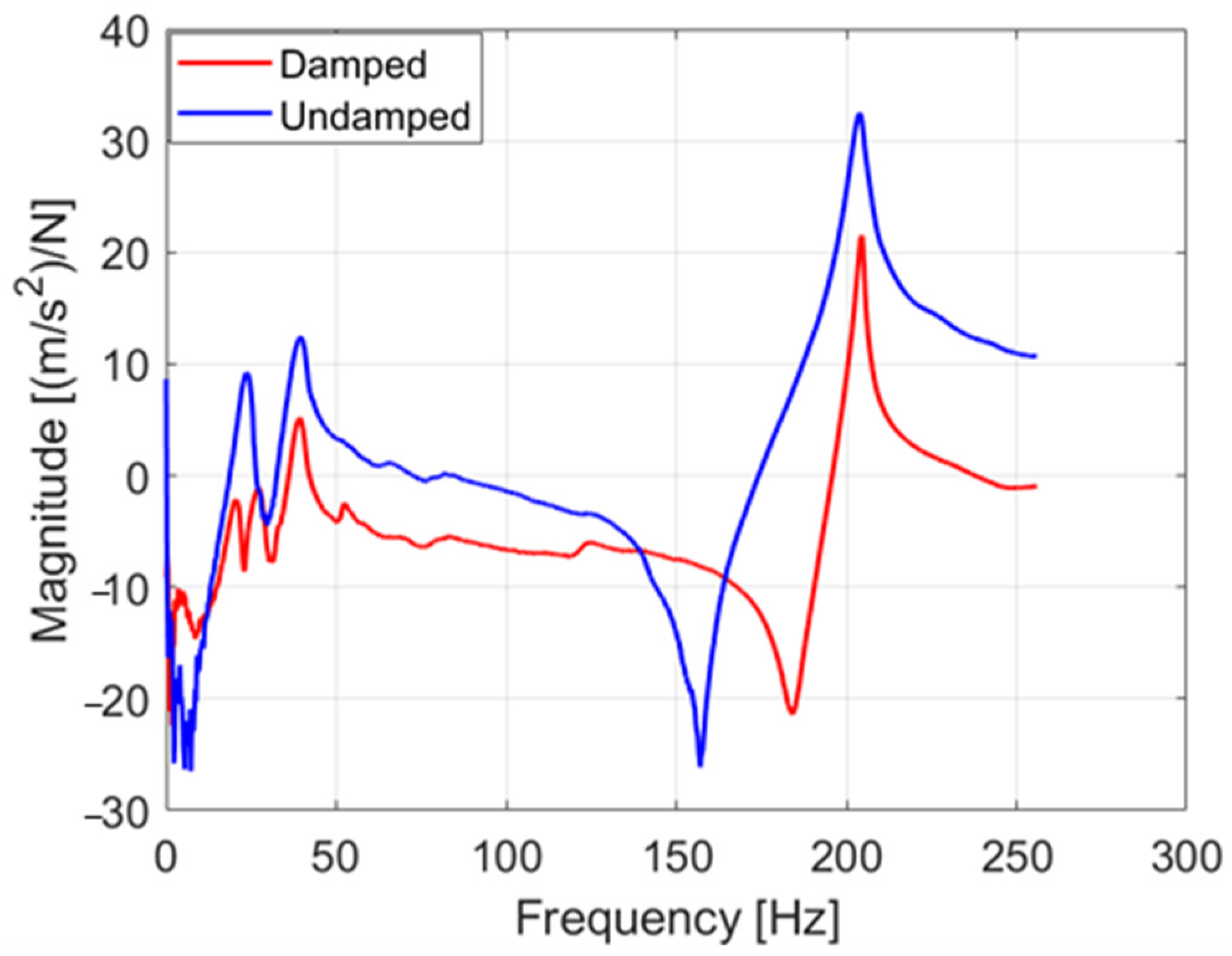
To assess the effectiveness of the prototype in mitigating torque fluctuations, two types of measurements were performed. First, a structural frequency response test was carried out with the TMD mounted. The resulting FRF magnitude was compared to that of the undamped system (
Figure 19). The amplitude of the first torsional resonant peak was significantly reduced, demonstrating the TMD’s capacity to attenuate the primary source of damaging vibrations. According to vibration theory, optimal damping is achieved when the two induced resonance peaks exhibit approximately equal magnitudes. In this case, the amplitude reduction corresponds to a factor of roughly 16, highlighting the substantial mitigation effect provided by the TMD.
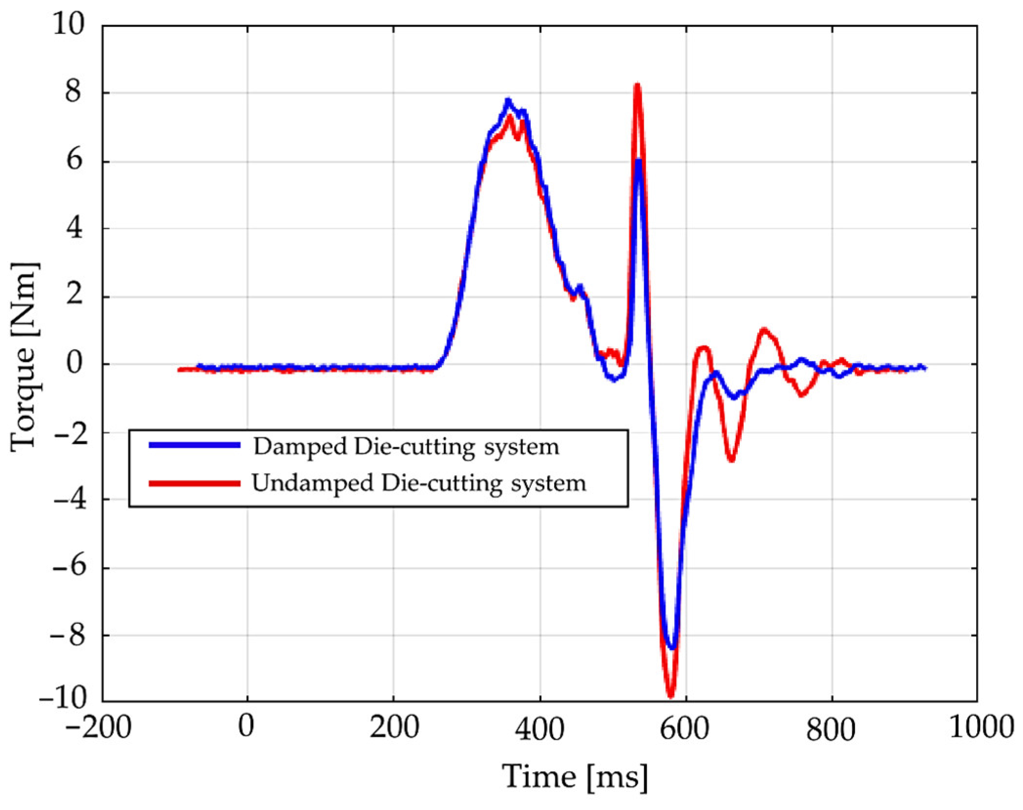
In addition, the influence of the TMD on the rotor’s operational torque was evaluated during several cutting cycles.
Figure 20 presents the motor torque diagrams, showing a clear reduction in both oscillation amplitude and timing, confirming the damper’s effectiveness under real operational conditions.
These tests were not conducted on the same machine as the data in
Figure 2. Due to limited availability, the measurements were performed on a similar machine at an intermediate stage of assembly. Nevertheless, despite minor differences in configuration, the beneficial impact of the TMD is clearly evident, demonstrating its robustness and effectiveness in reducing torsional vibrations.
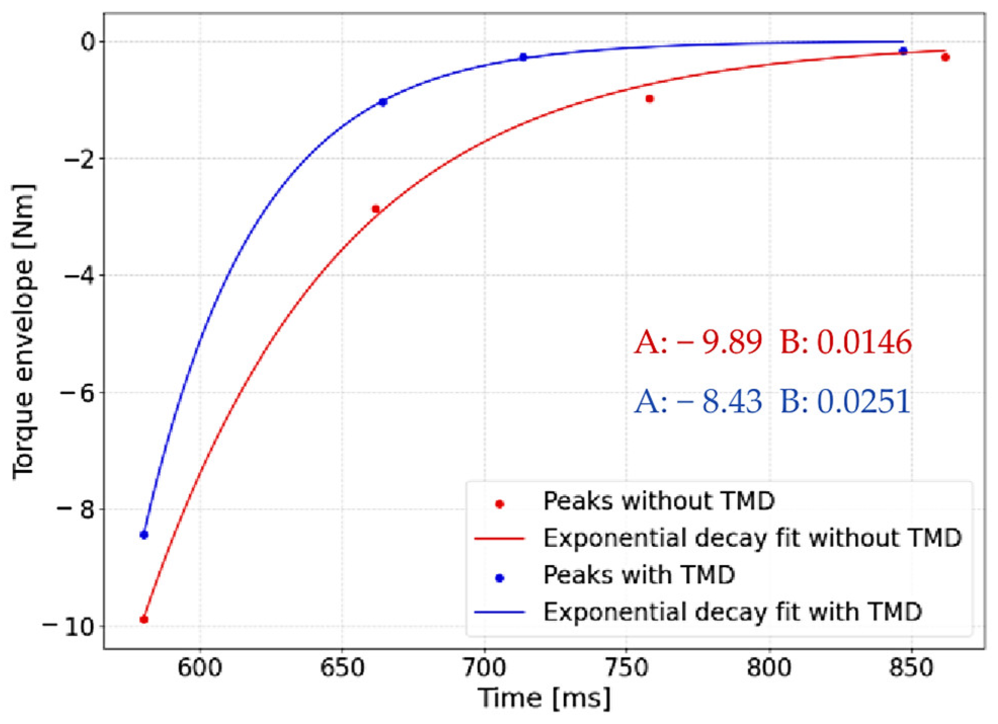
To quantify the TMD performance, the envelope of the peaks before and after applying the device was fitted with an exponential curve.
Figure 21 compares the resulting decay trends, focusing on the negative peaks because of their larger magnitude. The envelope curve follows Equation (13):
Finally,
Table 8 presents the comprehensive results of the TMD application. The key objectives defined in the introduction have been fully satisfied: the damping coefficient increased by over 70%, exceeding the targeted 20% decay rate, and the reduction in the first three resonance peaks confirms that the validation criterion (≥10% amplitude reduction) is achieved.
7. Conclusions
This study has addressed the challenge of torsional vibrations in rotating machinery, demonstrating that the implementation of the tuned mass damper (TMD) provides an effective and practical mitigation strategy. A thorough investigation of the Carton Wrap (CW) die-cutting system offered both theoretical and experimental insights into torsional resonances and the potential of passive damping solutions.
The analytical framework clarified the mechanism’s driving rotor resonance and underscored the TMD’s ability to significantly attenuate dominant response peaks. Complementary experimental characterization provided direct evidence of operational challenges, while the multibody model offered a detailed understanding of system dynamics and resonant interactions.
Designing the damper was the most critical stage, requiring a careful balance between theoretical requirements and practical constraints of industrial implementation. The incorporation of adjustable slots for tuning the radial position of the anti-vibration mounts enabled precise control of the torsional frequency, resulting in a robust and adaptable device suitable for varying operational conditions.
Experimental validation confirmed the effectiveness of the TMD: frequency response tests demonstrated a substantial reduction in the fundamental resonance amplitude, and motor torque measurements revealed a marked improvement in dynamic stability. These results highlight the potential of passive damping as a reliable, low-maintenance solution for high-speed die-cutting machinery.
In conclusion, this work contributes both to the fundamental understanding of torsional vibration phenomena and to the development of a validated engineering solution. The proposed passive damper, rigorously substantiated through modelling, design, and testing, emerges as a powerful tool to enhance the stability, robustness, and overall performance of industrial rotors. Future research may focus on long-term performance, assessing damage mitigation over extended operation and exploring broader applications across different industrial machines.
