Article

Structural Design and Analysis of an Automated Cutting Device for a Grass Carp Product Based on SolidWorks

1
School of Mechanical Engineering, Wuhan Polytechnic University, Wuhan 420023, China
2
School of Material Science & Chemical Engineering, Hubei University of Technology, Wuhan 430068, China
3
School of Materials Science and Engineering, Huazhong University of Science & Technology, Wuhan 430074, China
*
Author to whom correspondence should be addressed.
Machines 2025, 13(12), 1081; https://doi.org/10.3390/machines13121081 (registering DOI)
Submission received: 14 October 2025 / Revised: 13 November 2025 / Accepted: 20 November 2025 / Published: 24 November 2025
(This article belongs to the Special Issue Design and Manufacture of Advanced Machines, Volume II)

Abstract

When addressing the issue that the current market sales of fresh aquatic products, which are segmented into sections, mainly rely on manual operations, there are problems such as high labor intensity, low cutting efficiency, and uneven cutting. This paper designs an automated cutting device based on the commonly used grass carp as the object. Firstly, two efficient cutting schemes were proposed and compared. The optimized cutting scheme was designed using the SolidWorks software 2021. Then, three optimized schemes for the automatic clamping module, transmission module, and pushing module were designed. Subsequently, the structural design and calculation analysis of the key internal components were carried out to build the three-dimensional model of the automatic grass carp cutting device, and the cutting prototype was manufactured. Finally, an automated cutting prototype was fabricated based on the above-mentioned optimized design schemes, and relevant tests and analyses were conducted. The results showed that the prototype device can cut grass carp with a length of 300 ± 5 mm, with a processing capacity of 200 kg/h. The surface damage rate is less than 5%, and the cutting efficiency has been improved while the surface damage rate has significantly decreased. Therefore, the device manufactured through this design can meet the rapid processing, cutting, and various specific processing requirements of grass carp and other fresh aquatic products, providing a feasible solution for aquatic product cutting manufacturing equipment.

1. Introduction

The traditional manual cutting method is limited by factors such as high labor intensity and low operation speed [1]. The daily processing capacity of a single piece of equipment is usually no more than 2 tons. However, an automated cutting device, driven by servo motors and precisely controlled PLC, can achieve a stable production capacity of 600–800 kg/h (data from the Chinese Academy of Fishery Sciences in 2025), with an efficiency increase of more than three times. For instance, after a large aquatic product enterprise introduced an automated production line, its annual processing capacity increased from 50,000 tons to 150,000 tons, and its labor costs decreased by 40% [2,3]. Manual cutting is susceptible to the operator’s proficiency, and the product specification error is generally larger than ±5 mm. The machine vision-positioning and high-precision servo knife sets were integrated into the automated equipment, which controls the cutting error within ±0.5 mm, meeting the export standards of high-end markets, such as the EU and Japan [4,5,6]. Simultaneously, the closed design reduces the risk of microbial contamination, and the total bacterial count of the product decreases by 60% (data from ISO 4833-1 testing [7]). As the core unit of an intelligent factory, the automated cutting device can seamlessly connect with the MES system to achieve real-time monitoring of the production data (such as tool wear warning, energy optimization). A certain enterprise in Qingdao increased its raw material utilization rate by 7% and achieved an annual increase of over 10 million yuan through equipment networking. In addition, the breakthrough of domestic equipment (with a price only one-third of the imported equipment) helps small and medium-sized enterprises upgrade their technology and promotes the overall competitiveness of the industry [8]. Compared with the traditional processing method, the automated equipment can reduce energy consumption by more than 20% and reduce raw material waste through precise cutting. It is estimated that each piece of equipment will reduce carbon emissions by 12 tons per year, which is in line with the “dual carbon” strategic goal [9].
The traditional manual cutting method not only has the aforementioned problems, but also has the following three issues [10,11]: (1) the size accuracy depends on the workers’ experience, with errors often exceeding ±5 mm; (2) mechanical compression is prone to causing blood stasis on the fish body surface or muscle fiber rupture, resulting in an injury rate of approximately 15–20%; (3) the workers’ rhythm limits the processing speed, and the single-line production capacity is usually no more than 80 fish per hour. Therefore, it is necessary to design and manufacture an automated cutting device for aquatic products to address these deficiencies, which not only improves the efficiency of the cutting process, but also reduces the damage rate of the fish body’s cross-section.
The main process of fish processing involves several key steps, including scaling, internal organ cleaning, body cleaning, head and tail removal, and cutting. Among these processes, the segment-cut is particularly important, and the quality of the operation is not only related to the quality of the final product, but also directly affects the actual yield of the fish meat [12,13,14]. One is a fixed-length cutting method based on a fixed-length standard, and the other is a quantitative cutting method based on weight. These two processes have their own characteristics and can meet the processing requirements of fish products in different application scenarios [15,16]. Fixed-length cutting ensures consistent product specifications by setting a uniform length, while quantitative cutting improves raw material utilization by precisely controlling the weight of a single section. Together, they form the mainstream cutting technology solution in modern fish processing [17,18]. The processing principle of fixed-length cutting is relatively simple and easy to achieve in a mechanized operation. The popular cutting techniques at home and abroad mainly include metal tool cutting, water jet cutting, and ultrasonic vibration-assisted cutting [19]. There are also some advanced intelligent cutting assistance technologies, such as visible light and near-infrared imaging, hyperspectral imaging, X-ray imaging, etc. These visual imaging technologies are used to identify fish body characteristics and achieve intelligent, customized cutting. The grass carp is a key species for freshwater aquaculture in China, with the annual output value exceeding 100 billion yuan. It drives the development of the entire industrial chain, including feed, processing, and logistics.
In conclusion, the traditional manual device for cutting fish bodies relies on manual operation, which is inefficient and involves a high labor intensity, leading to inaccurate cutting and affecting the integrity and appearance of the fish bodies. The simple tools are prone to wear and tear, resulting in high maintenance costs and making it difficult to meet the requirements of large-scale production. During the operation, there are safety hazards, and long-term use can easily cause fatigue and muscle strain. Therefore, it is necessary to develop an efficient automated device for cutting fish bodies.
This work aims to develop an efficient and automated cutting device specifically for live grass carp, addressing the issues of low efficiency and high damage rate in traditional manual cutting. The research scope includes SolidWorks 3D modeling, a design of the conveying system, optimization of the pushing mechanism, and mechanical analysis of key components. Finally, a prototype was constructed, and its performance was verified. Through multiple scheme comparisons and structural simulations, a modular design was innovatively adopted to achieve precise cutting of 50–400 mm, with a lower surface damage rate compared to traditional processes. The key innovations are as follows: (1) A dynamic balance pushing mechanism to prevent fish body slippage; (2) An adaptive knife set design to reduce tissue damage; (3) An integrated conveying-cutting system to enable continuous operation. This design provides a new paradigm for water product processing equipment that balances efficiency and quality.

2. Selection of Design Scheme

2.1. Design Ideas and Methods

There are numerous types of fish and aquatic products. Taking grass carp, which has a higher processing demand, as an example, the average body length of grass carp is approximately 3.4–4.0 times its height, and about 3.6–4.3 times its head length. It is 7.3–9.5 times the length of the tail base. The average body length of a normal-sized grass carp is approximately 250–300 mm, with a width of 150 mm and a thickness of 100 mm. Herein, the maximum body length is calculated to reserve sufficient design space. In the design of this cutting section device, the most important aspect is our cutting function, followed by the fish body transmission function during the cutting process. Additionally, due to the viscoelasticity of the cut fish pieces, we also need to design the function of pushing and collecting the cut fish pieces after the cutting is completed. Moreover, as this study mainly focuses on non-frozen fish bodies, it is necessary to consider the influence of the fish body’s sliding during the process on the cutting. Furthermore, during the cutting process, a clamping function should also be set up to ensure a stable environment for the fish’s body. The pushing function and the transmission function work together with our cutting function to fulfill the segmented cutting requirements of our fish products.
In addition, this research employed a servo motor drive, PLC control system, MEMS system, visual positioning, etc., to achieve precise control and monitoring of the cutting and processing of aquatic products. The flowchart of the specific control system is shown in Figure 1. In the automated cutting control system, MEMS sensors, visual input, and servo feedback work together to form a closed-loop control circuit. The MEMS sensors continuously monitor the movement state and position of the fish body and convert physical quantities into electrical signals; the visual system captures image information of the workpiece position and cutting path through the camera; these data are analyzed and processed by the microprocessor, compared with the preset parameters, and then generate control instructions. The servo system drives the actuator to make precise adjustments according to the instructions, and at the same time, its built-in encoder provides real-time position feedback to the controller, thereby achieving the dynamic correction and optimization of the cutting process.

2.2. Selection of Design Plan

2.2.1. Selection of Cutting Schemes

The subjects of this study were metal cutting tools, and linear cutting and involute cutting were the most common cutting methods [20]. The former cuts objects through linear motion, while the latter cuts objects through circular motion by connecting one end of the tool to the motor shaft. A planar blade is the main cutting tool in linear cutting, which is easier to achieve compared with involute cutting and has a simpler corresponding structure. Therefore, linear cutting is adopted in this device. There are mainly two types of linear cutting schemes.
(1)
Line saw cutting or circular saw cutting
There are multiple wire saws or circular saws installed on a rotating shaft. The fish body passes through its front, and the entire fish body is cut in one [21,22] go through the rotating cutting action of the wire saw or circular saw.
(2)
Knife cutters-type blade cutting
The fish body is placed on a transmission device with intermittent motion characteristics, and in conjunction with a cutter moving from top to bottom, the cutting of the fish body is completed through the pressure-cutting effect of the cutting blade [23]. During the cutting process, only one section is cut at a time, and in conjunction with the intermittent transmission device, the entire fish body is cut [24].
Option one has a relatively high cutting efficiency. With the help of multiple circular saws or wire saws, the entire fish body can be cut into sections at one time. However, the drawback is that the rotating cutting method causes significant damage to the surface of the cut fish [25,26,27]. The fish meat fibers themselves are relatively tender, which can cause considerable damage to the cut surface and affect the taste of the fish meat. In addition, the forward cutting method of Scheme 1 is not convenient for the pressing action during the cutting process and is only suitable for frozen fish. Scheme 2 is relatively less efficient, but the cutting tool is a pressure-cutting action, which causes less damage to the cutting surface, is more esthetically pleasing, and has less impact on the taste of the fish compared with the rotary cutting method. The subjects of this study are non-frozen fish, which have higher requirements for taste, and Scheme 2 cuts from top to bottom. It is more suitable for devices that act by pressing the fish’s body. The last point is that the knife switch cutting can control the cutting spacing and cutting time more freely by controlling the spacing of the knife switch cutting [28,29,30].
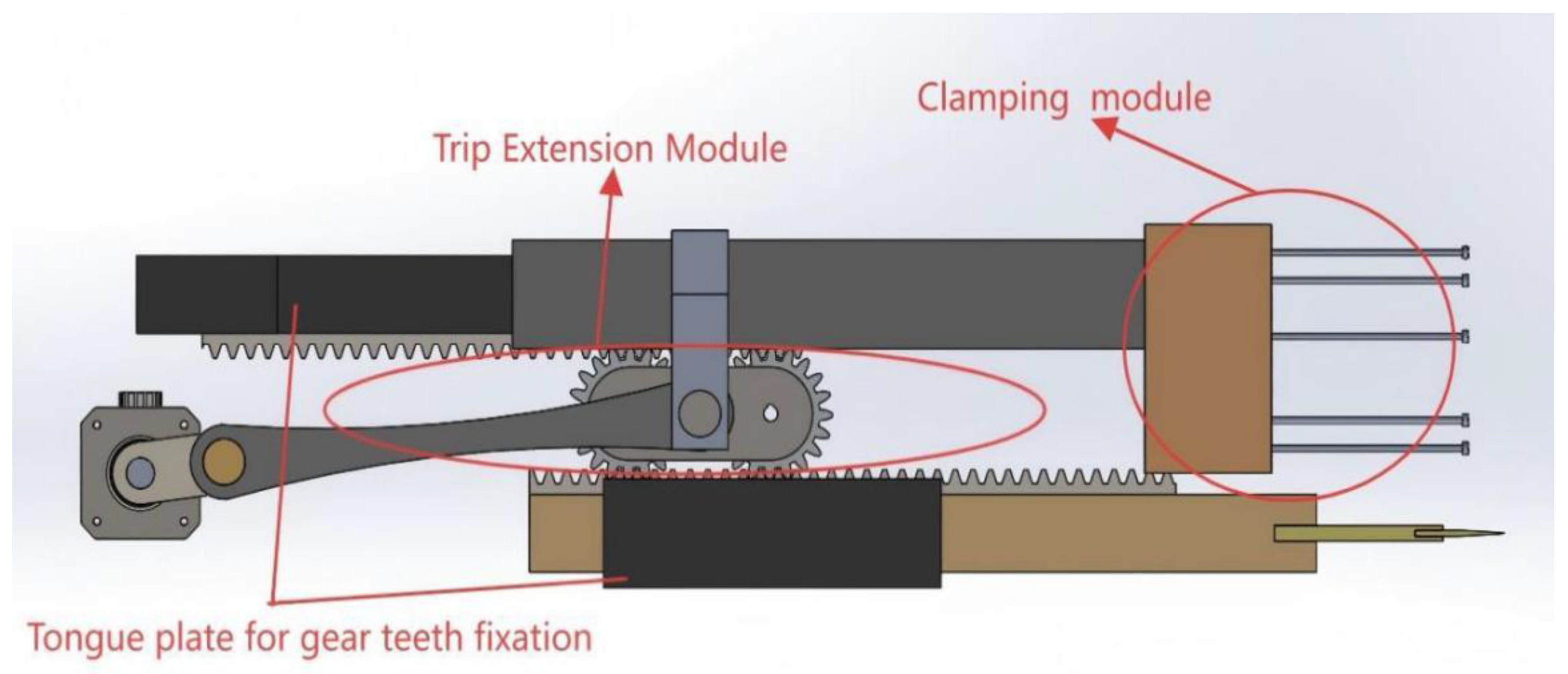
Taking all the above into account, the cutting scheme chosen here is Scheme 2, that is, the knife switch cutting. The transmission scheme for completing the cutting action and the clamping module during the cutting process is described below. The cutting and clamping module is shown in Figure 2.
The drive system uses a servo motor as the power source. The servo motor is connected to the crank mechanism through an elastic coupling. When the motor rotates, it drives the crank to make a circular motion [11,31]. The crank mechanism is designed with symmetrical balance, with two identical long connecting rods arranged symmetrically on the fixed shaft of the crank. This symmetrical structure can effectively counteract the lateral force during movement and improve the stability of the system. One end of the long connecting rod is hinged to the crank, and the other end is connected to the gear connection plate through a pin shaft, on which two standard gears with the same parameters are installed, and these two gears mesh with the upper and lower arranged racks, respectively. The rack system consists of a fixed rack and a movable rack: the fixed rack (rack fixing plate 1) is bolted to the frame and serves as the reference for motion; the movable rack (rack fixing plate 2) is mounted within a precision linear guide and can move in a straight line along the guide, with a cutting tool installed at its end. On the outside of rack fixed plate 1, a sliding guide rail is added, which is rigidly connected to the gear connection plate through a connecting piece, allowing the guide rail to move synchronously with the gear movement.

2.2.2. Design of Clamping Module

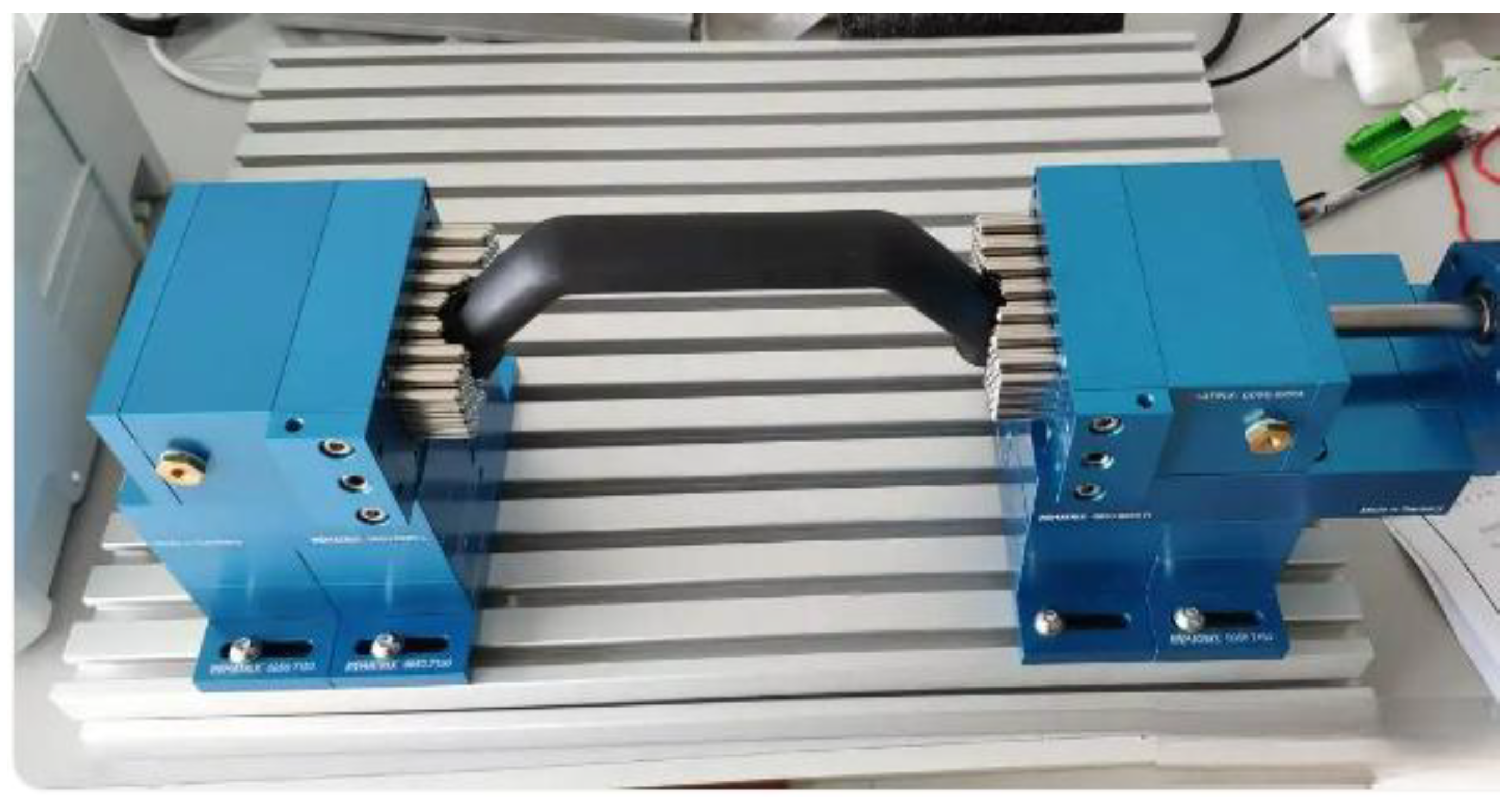
The operation process of the clamping module can be described in detail as follows: when the servo motor receives the control signal and starts to rotate, its output shaft drives the crank mechanism to perform circular motion through a high-precision coupling. Since the crank is connected to two symmetrically arranged long connecting rods by a hinged connection, and the other end of the long connecting rods is rigidly connected to the gear fixing plate via a pin shaft. When the crank completes a 360-degree rotation, it will drive the gear fixing plate to perform a precise reciprocating motion on the linear guide rail. The movement stroke of the gear fixing plate is exactly twice the radius of the crank (that is, twice the length of the crank). The working principle of the clamping module is based on the German MATRIX fixture [31], as shown in Figure 3. According to this principle, it can be applied to the clamping device that can tightly grip different fish body surfaces. The other end of the sliding guide rail is connected to the clamping module. When the cutting tool cuts, the clamping module will first contact the fish body and apply an appropriate clamping force under the action of the spring, which not only prevents the fish body from moving, but also avoids damaging the fish meat.
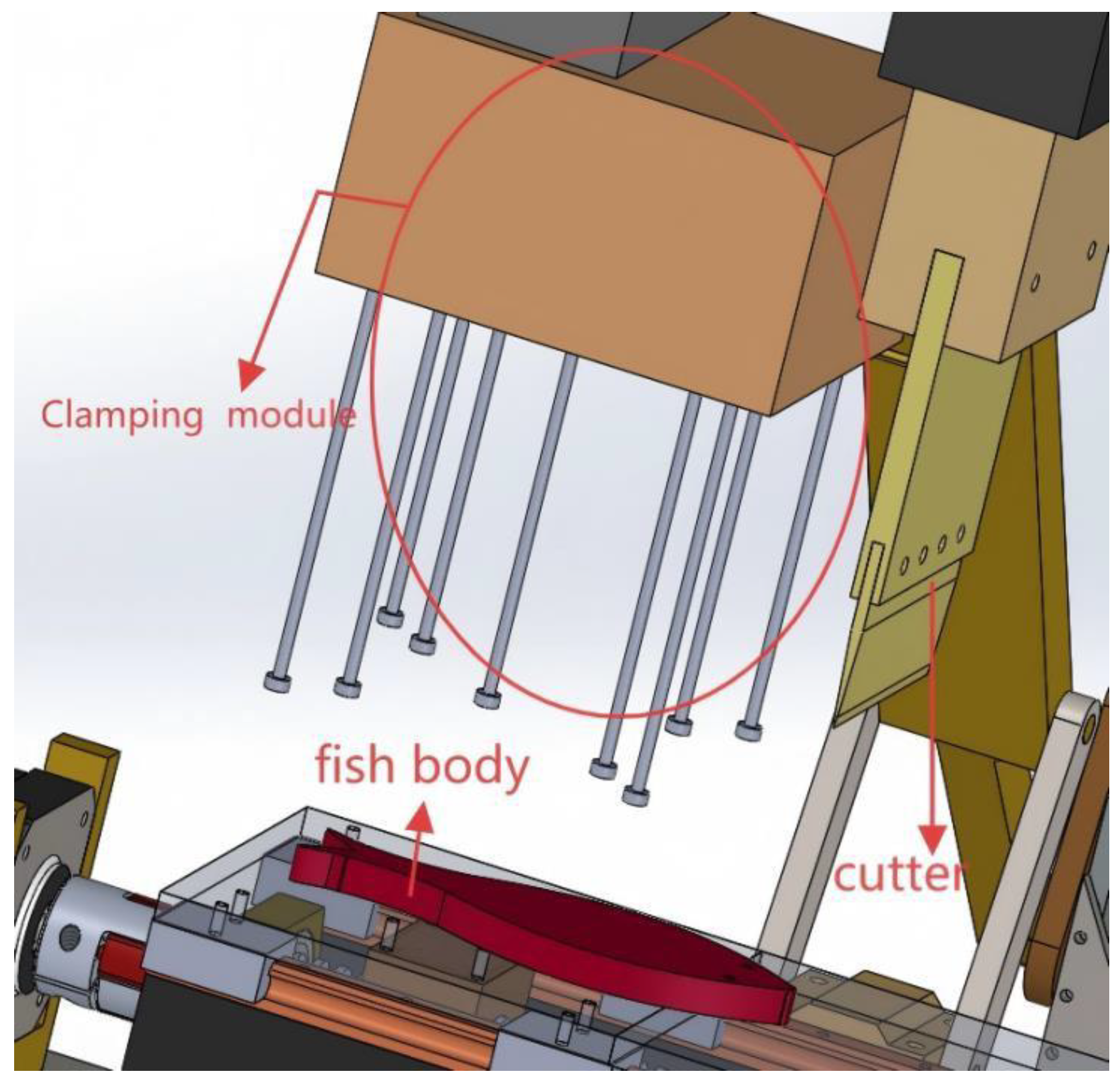
The entire transmission chain converts the rotational motion of the motor into the reciprocating swing of the gear through the crank connecting rod mechanism, and then converts the swing into the linear cutting motion of the cutting tool through the gear rack pair. Simultaneously, it drives the clamping module to act in coordination, achieving the automation and precise control of the cutting process. The flexible clamping module is shown in Figure 4. Two standard gears with exactly the same parameters are installed on the gear fixing plate. The axes of these two gears will perform synchronous linear reciprocating motion along with the fixing plate. It is worth noting that these two gears form a meshing transmission with the fixed and movable toothed strips, respectively: the lower fixed toothed strip is rigidly connected to the frame through a bolt as the motion reference, while the upper movable toothed strip is installed in the movable toothed strip fixing plate.
In the automatic cutting device, the design of the clamping mechanism should take into account both stability and hygiene. For example, a spiral or wedge mechanism is used to ensure self-locking, and stainless-steel material is selected with a smooth surface to reduce the accumulation of residues. The calculation of the clamping force needs to comprehensively consider the cutting force, inertial force, and safety factor. The actual required clamping force is determined through the principle of balanced torque to avoid the deformation or loosening of the workpiece. The motor control limit needs to be designed based on the output torque and travel parameters to ensure the stable driving of the clamping mechanism at high-speed cutting and real-time monitoring through sensors to prevent overload. The hygiene design criteria emphasize easy cleaning, such as using a detachable structure, a no-dead-corners design, and compliance with industry standards (such as ISO22000 [32]) to meet the hygiene requirements in food or pharmaceutical fields.

2.2.3. Transmission Scheme Selection

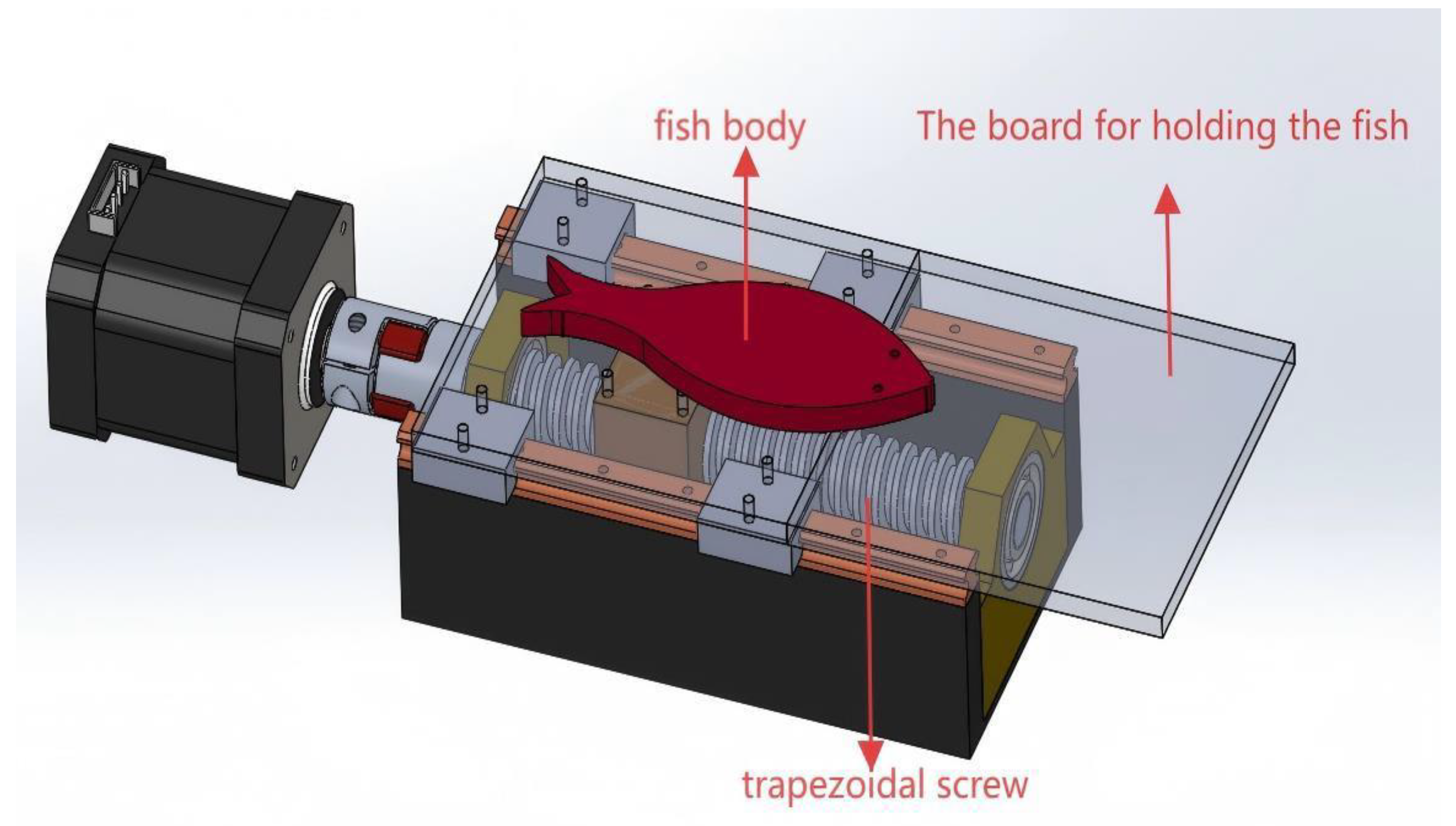
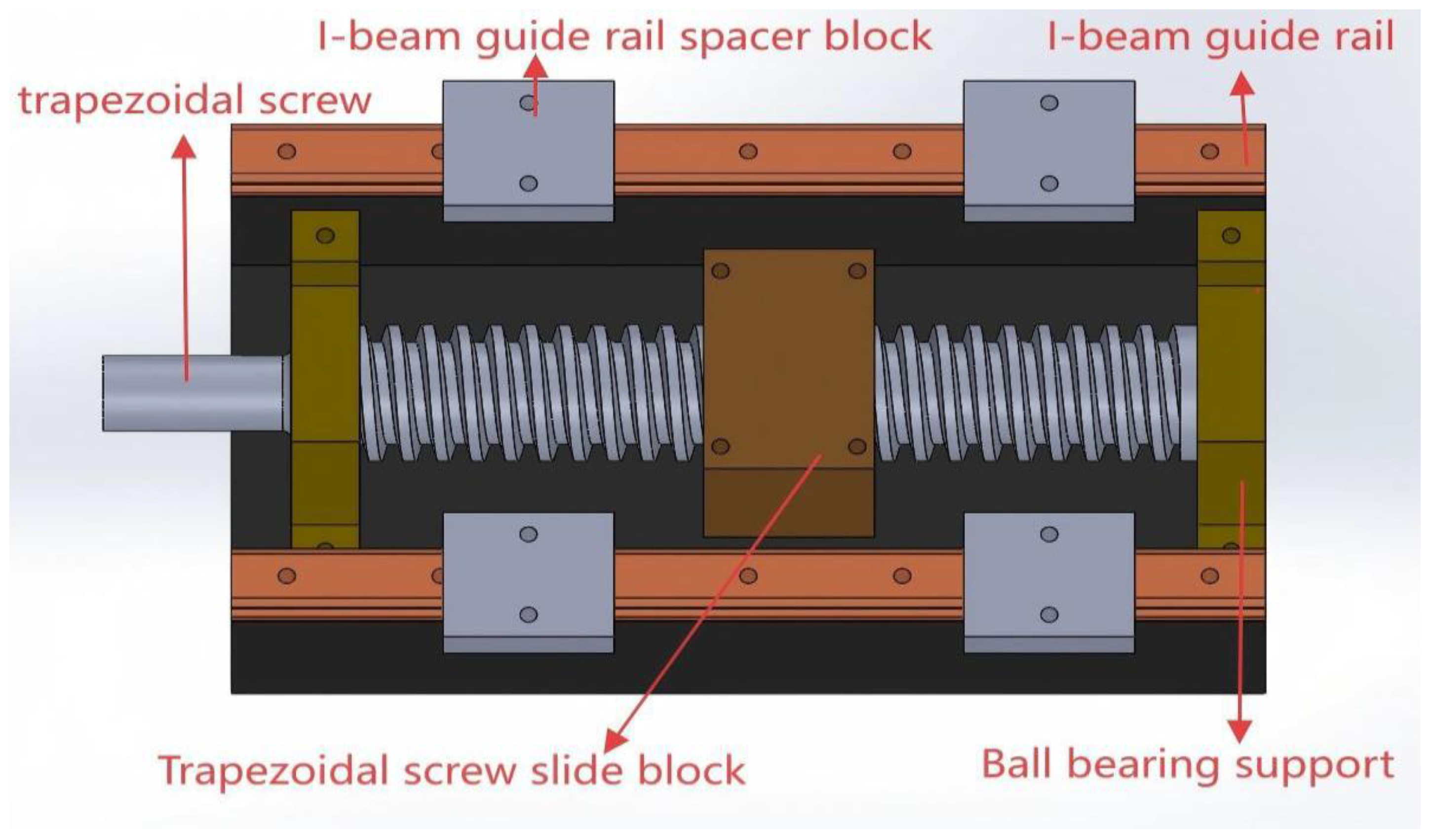
There are mainly two transmission methods: conveyor belt transmission and lead screw slide table type transmission. The advantage of conveyor belt-type transmission is that the transmission structure is simple and the maintenance cost is low [33,34,35]. The disadvantage is that there is elastic sliding, and the transmission accuracy cannot be guaranteed. The advantage of the lead screw slide-type transmission is that the transmission degree is precise, and the transmission distance and time interval can be controlled more precisely, but the disadvantage is that the cost is higher and the maintenance is more difficult. Considering that the cutting of the subject in this study requires intermittent cutting with a knife switch tool, there is a certain requirement for the transmission accuracy of the transmission scheme. Therefore, a trapezoidal lead screw slide transmission is chosen in this transmission scheme. The transmission module is shown in Figure 5. The transmission process is shown in the Supplementary Materials Video S1.
The trapezoidal lead screw rotates precisely under the drive of the servo motor. The special thread structure of the trapezoidal screw meshes with the threads in the inner cavity of the trapezoidal screw jacket, converting the rotational motion into linear motion and driving the trapezoidal screw jacket to move axially [36,37,38]. The upper end of the trapezoidal screw slider is rigidly connected to the fishplate, which ensures the synchronization and reliability of motion transmission, allowing the linear displacement of the trapezoidal screw sleeve to be accurately converted into the horizontal movement of the fishplate. Two I-shaped track pads are added on both sides of the lead screw to increase the stability of the chopping board platform and prevent it from tilting due to the uneven distribution of gravity. The special cross-sectional shape of the I-shaped track pad fits perfectly with the guide grooves of the fish board pad block to form a stable sliding pair. The transfer relationship of the entire movement chain is as follows: rotation of the trapezoidal screw → axial displacement of the outer sleeve of the trapezoidal screw → horizontal movement of the fish placement board → synchronous displacement of the fish placement board pads. The system precisely regulates the start and stop timing of the motor through the PLC control system to achieve intermittent rotation control. This intermittent motion mode perfectly meets the technological requirements of fish meat block processing. Each movement interval corresponds to one cutting action. By adjusting the interval time and moving distance, the size and specification of the fish block cutting can be flexibly adjusted. Ultimately, an automated and standardized fish meat block processing procedure is achieved. The core structure of the transport module is shown in Figure 6.
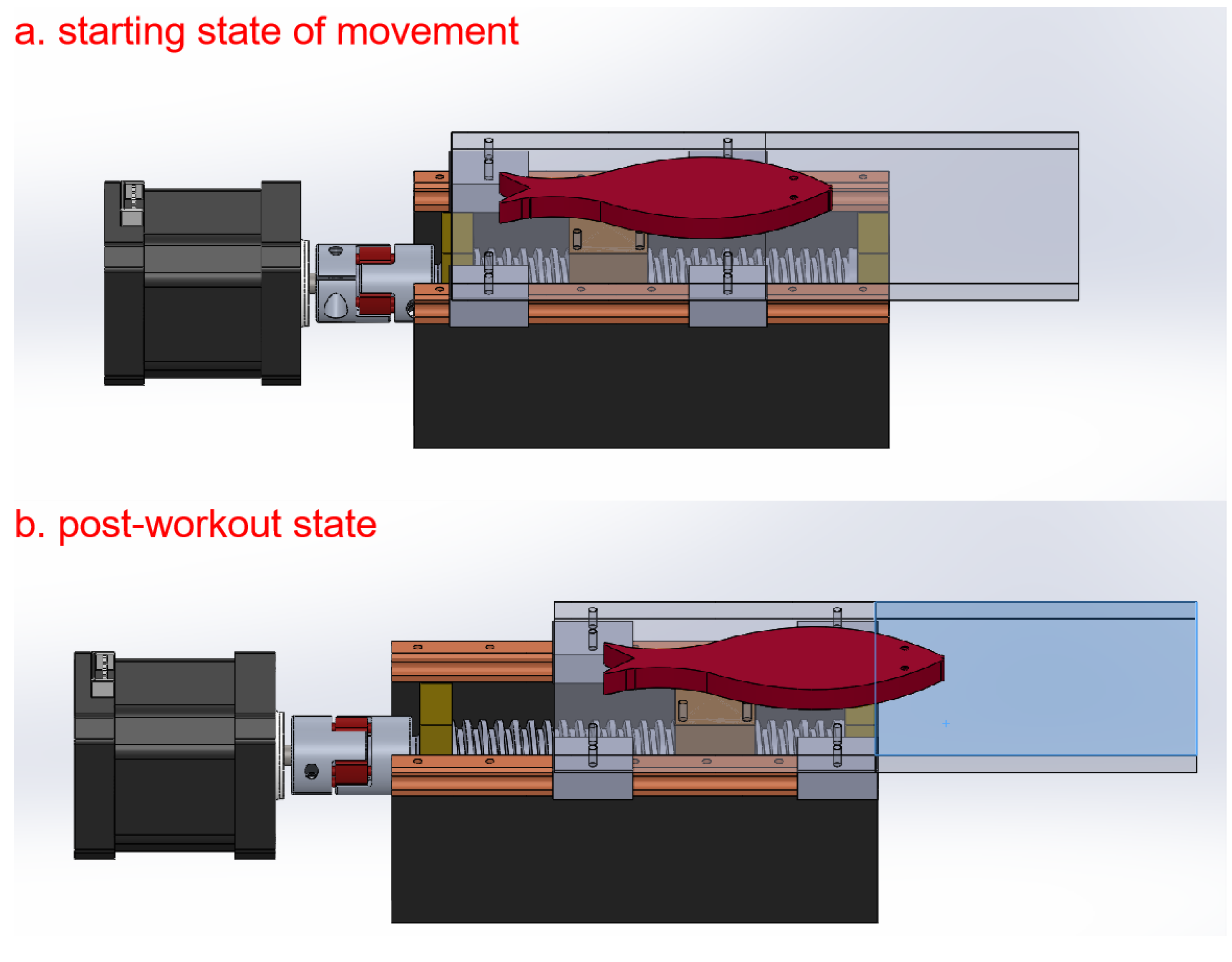
The design of the entire transmission system fully considered its load characteristics, motion accuracy, and long-term operational stability requirements. It possesses lots of technical advantages, such as a compact structure, smooth transmission, and accurate positioning. The initial state and end state of the transmission module are shown in Figure 7.

2.2.4. Push Scheme Selection

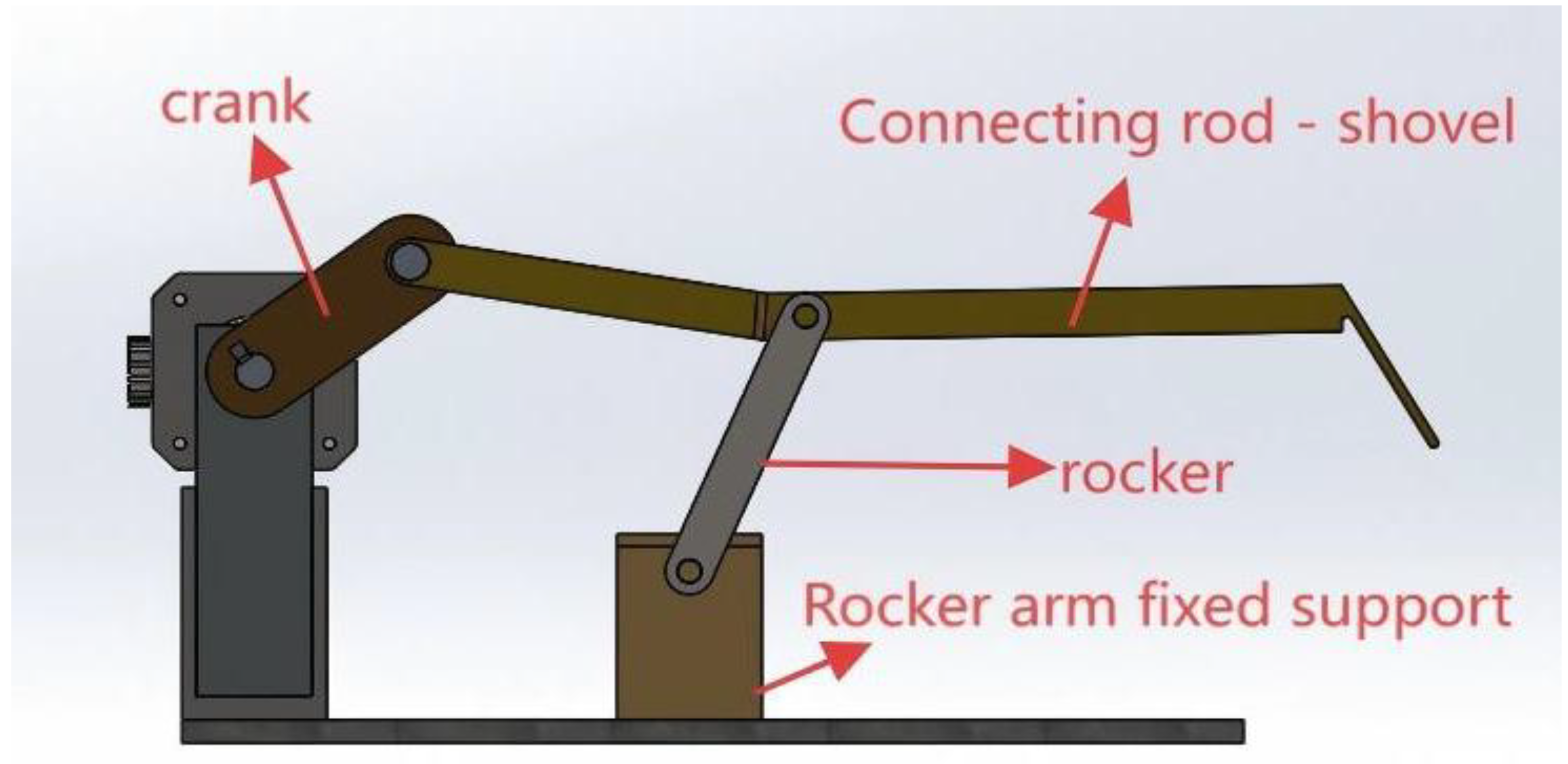
In the process of automated block cutting of fish meat, due to the significant viscoelastic properties of the fish meat itself, when the cutting knife applies a vertical downward cutting pressure, the fish meat tissue will adhere tightly to the contact surface of the fish placement plate by intermolecular forces. At the same time, due to the horizontal arrangement of the fish placement plate, the cut fish pieces are difficult to be automatically separated by gravity alone and remain attached to the plate surface [39]. Under this condition, the system lacks an effective active drive mechanism to overcome the adhesion force between the fish meat and the board surface, resulting in the cut fish blocks not being able to automatically detach from the surface of the fish placement board, thereby affecting the subsequent centralized collection operation process. To solve this technical problem, a special push power device needs to be added at the rear end of the cutting station. Through the mechanical actuator, a horizontal thrust is applied to enable the fish blocks to overcome the surface adhesion force and achieve reliable separation and eventually push the scattered fish blocks to a unified collection area, thus ensuring the continuous automation of the entire cutting production line. The design of the push device needs to consider the physical properties of the fish blocks, the surface treatment process of the fish placement plate, and the precise control of the push force, in order to achieve stable and efficient fish block separation and collection functions. The push module is shown in Figure 8.
The core mechanical structure of the push module is based on the classic crank-rocker mechanism principle. The module is mainly composed of key components such as the bottom fixing plate, stepping motor, crank-fixing support, crank, connecting rod (whose end serves as the push execution end), rocker, and rocker fixing support. In the mechanism design, particular attention is paid to the optimization of the length parameters of each member: the center distance of the two through holes of the crank is 300 mm, the center distance of the two connecting through holes is 621.6 mm, and the center distance of the two connecting through holes of the connecting rod is 450 mm. These precisely calculated size parameters together ensure that the motion trajectory of the actuating end presents an ideal linear feature during the push stage.
The entire push process begins with the rotational drive of the stepping motor, the motor output shaft drives the crank to perform uniform circular motion, and through the transmission effect of the connecting rod, under the constraint of the rocker mechanism, the circular motion at the end of the crank is converted into approximately linear reciprocating motion, thereby achieving a smooth push of the fish blocks on the opposite fish plate, and finally accurately sending the fish blocks into the collection box below. This device has been meticulously designed to take into account the kinematic characteristics, structural stiffness, and transmission efficiency. While ensuring the pushing accuracy, it also possesses the advantages of stable operation and easy maintenance, fully meeting the operational requirements of the automated production line.
The kinematic analysis of the thrust trajectory requires the establishment of a multi-body system error transfer model to quantify the influence of positioning deviation, straightness error, and rotational angle error on the trajectory accuracy; the structural error analysis focuses on the geometric accuracy attenuation caused by thermal deformation and force deformation and evaluates the combined effect of cumulative errors on cutting accuracy through tolerance stacking. Synchronous time control needs to be combined with the trajectory dynamics model to optimize the thrust acceleration constraints, ensure the matching of the motion sequence with the cutting action, and avoid cutting quality defects caused by timing deviations.

3. Design of Some Major Parts

3.1. Equipment Processing Procedure of the Device

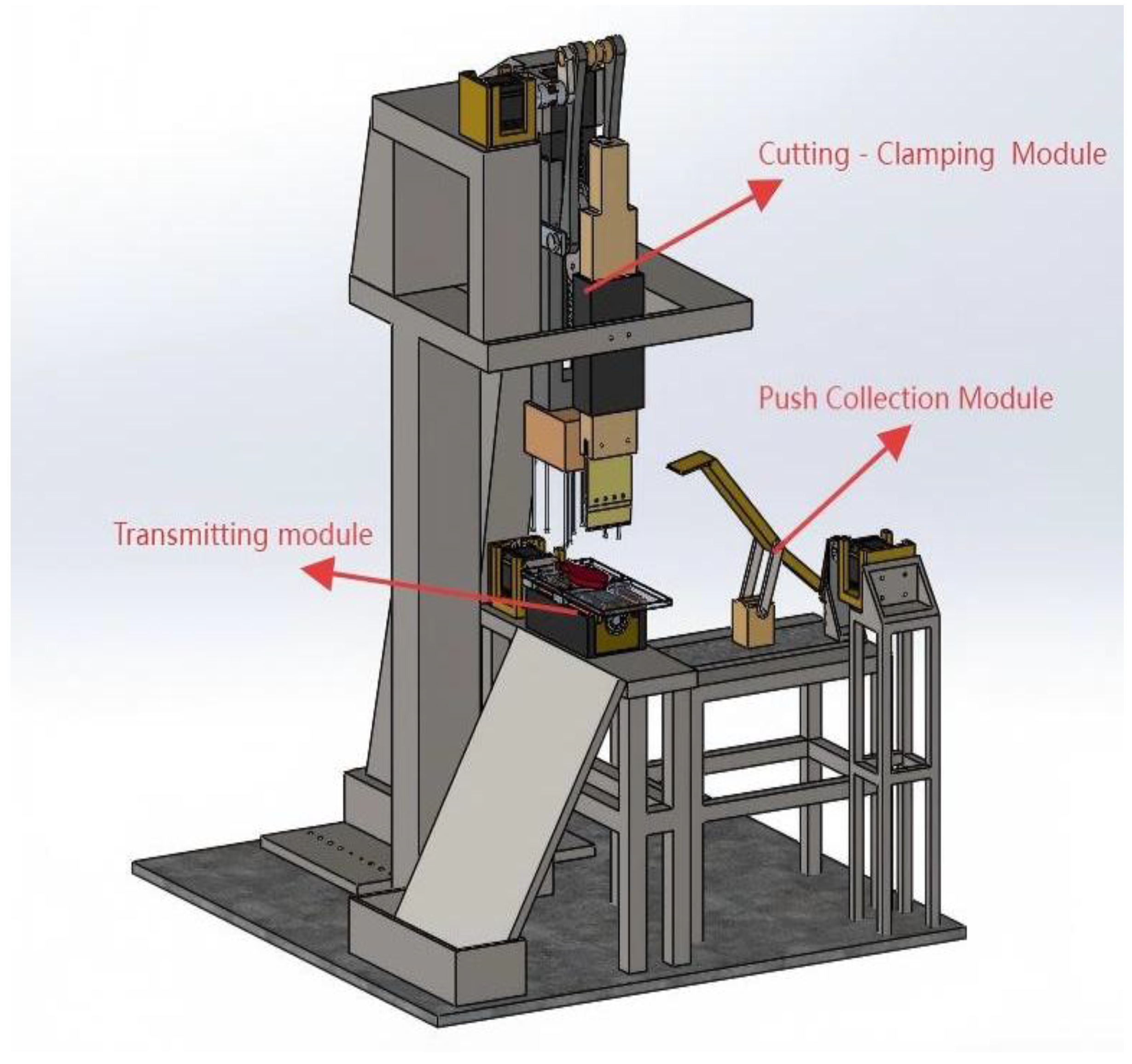
As shown in Figure 9, on the automated processing production line, the conveying module, as the material transportation unit of the entire system, uses a servo motor as the power source. The motor is connected to the precisely machined trapezoidal screw through a coupling, and the surface of the screw is specially treated to ensure its wear resistance. The trapezoidal screw precisely cooperates with the threaded groove in the outer sleeve, which not only ensures the transmission accuracy but also has self-locking characteristics. The push plate slides smoothly on the guide rail through linear bearings. The electronic control system achieves closed-loop control through sensor feedback, ensuring that the fish’s body can accurately stop at the preset position.
The cutting module is the core component that guarantees the processing quality, and its power also comes from a servo motor [40]. The motor converts rotational motion into linear motion through a crank-linkage mechanism, driving the cutting tool to make reciprocating cuts on the precise guide rail. The cutting tool is made of high-carbon stainless steel and undergoes special heat treatment to ensure that the cutting edge remains sharp [41]. The clamping module adopts a spring pre-pressing structure, ensuring the stability of the cutting process. The cutting module uses a stroke extension structure, enabling the cutting tool and the clamping module to achieve synchronous movement through mechanical linkage. This design avoids the use of additional electrical control systems and improves system reliability. During the cutting process, the fish’s body remains in a stable compressed state, ensuring that the cut edge is neat and esthetically pleasing.
The pushing module adopts a crank-rocker mechanism design to convert rotational motion into a nearly linear pushing action. The pushing plate exerts a horizontal thrust on the fish piece after cutting, overcoming the stickiness and elasticity of the fish meat, and smoothly pushes the fish piece to the collection box to achieve automated collection.
These three functional modules, through precise mechanical coordination, have achieved the full-process automation from raw material input to product collection, ensuring stable performance in long-term operation. This systematic design not only improves the production efficiency but also ensures the consistency of the product processing quality.

3.2. Selection of Lead Screw

The cutting tool material used is SUS440C, with a hardness value of 60HRC. The lead screw is mainly used to drive the lateral movement of the fishplate above the transmission module. Herein, a trapezoidal lead screw with an outer diameter of 45 mm and a lead of 25 mm is selected. The calculation of the working length of the lead screw is as follows (1) [12].
L = l1 + l2 + l3 + l4
Herein, we have a threaded section length l1 = 245 mm.
The lead screw support frame needs two, and each support frame needs two bearings. The bearings selected are deep groove ball bearings with a thickness of 20 mm, and the total width of the support frame is designed to be 20 mm, thus Equation (2) is as follows [12].
l2 = 20 + 20 = 40 mm
Our lead screw is directly connected to our motor through a coupling, so this part needs to be included in the length of our lead screw, and at the same time, a certain rotational clearance needs to be left between the coupling and our bearings to prevent friction during their rotation.
Here we take l3 = 75 mm, and take l4 = 2 mm.
Based on this Equation (3) [12],
L = l1 + l2 + l3 + l4 = 245 + 40 + 75 + 2 = 362 mm

3.3. Design of Cutting Tools and Their Movement Processes

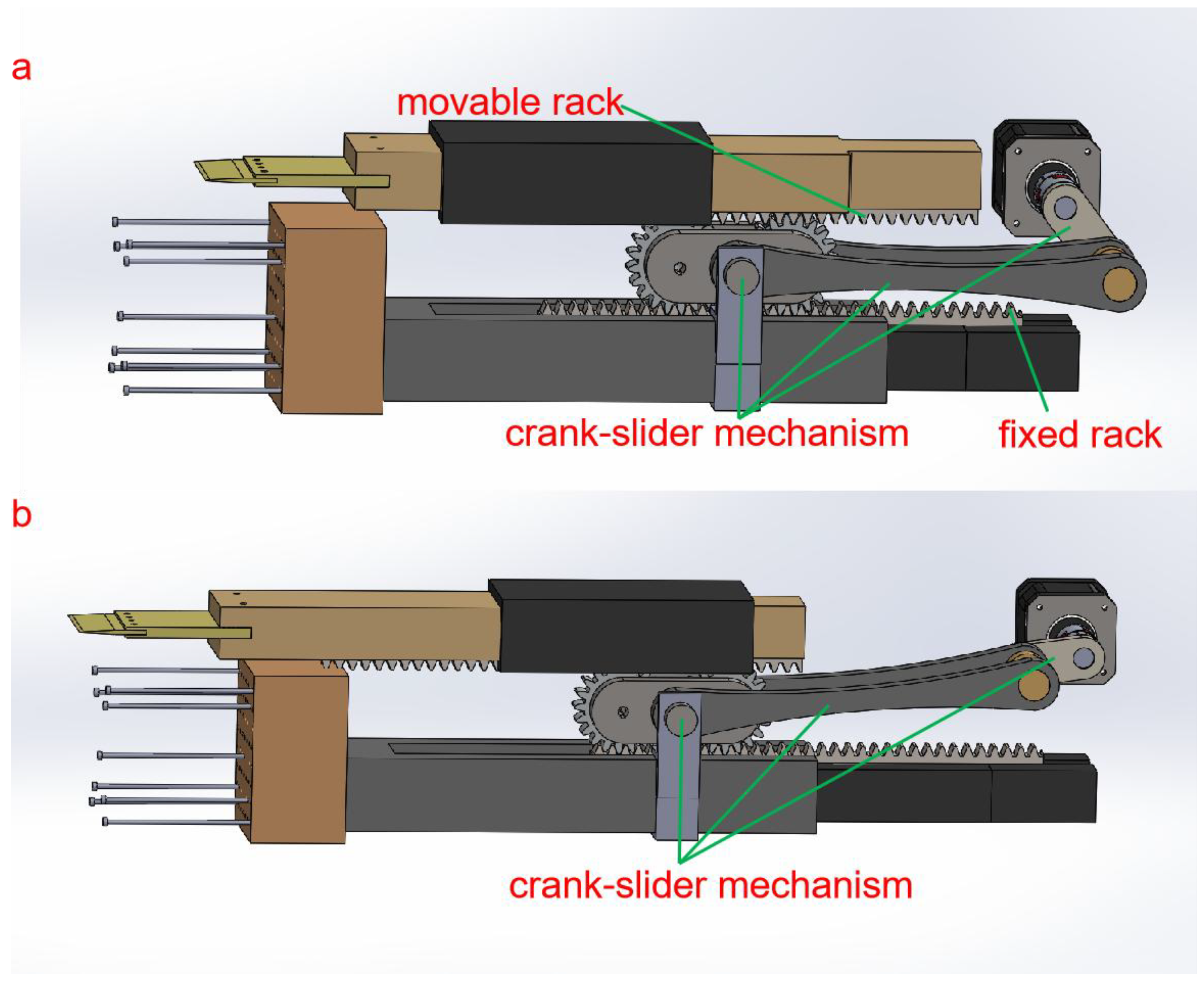
This cutting system utilizes a servo motor as its power source, enabling the tool to achieve a reciprocating cutting motion through a precise mechanical transmission mechanism. The design of the crank and connecting rod part of this module is shown in Figure 10. The system comprises three major components: the power transmission mechanism, the motion conversion mechanism, and the execution mechanism. The servo motor is connected to the crank mechanism by an elastic coupling. When the motor rotates, it drives the crank to perform a circular motion. The crank mechanism adopts a symmetrical balance design with two identical long connecting rods symmetrically arranged on the fixed axis of the crank. This symmetrical structure can effectively counteract a lateral force during the motion process and improve its stability. One end of the long connecting rod is hinged to the crank, and the other end is connected to the gear connection plate through a pin shaft. The connection plate is made of high-strength aluminum alloy material and is equipped with two standard gears of the same parameters, which mesh with the upper and lower arranged racks. The rack system consists of a fixed rack and an active rack: the fixed rack (rack fixed plate 1) is fixed on the frame through bolts, serving as the motion reference; the active rack (rack fixed plate 2) is installed in the precision linear guide rail and can move linearly along the guide rail, and its end is equipped with a cutting tool. To ensure the motion accuracy, the system also has a guiding mechanism: a sliding guide rail is added on the outside of the rack fixed plate 1, and this guide rail is rigidly connected to the gear connection plate through a connecting piece, allowing the guide rail to move synchronously with the gear when it moves, the other end of the sliding guide rail is connected to the clamping module, and when the cutting tool cuts the fish, the clamping module will first contact the fish body and apply an appropriate clamping force under the action of the spring, which not only prevents the fish body from moving but also avoids damaging the fish meat. The entire transmission chain converts the rotational motion of the motor through the crank connecting rod mechanism into the reciprocating swing of the gears, then converts the swing into the linear cutting motion of the tool through the gear rack pair, while also driving the clamping module to act in coordination, achieving the automation and precise control of the cutting process. The system design fully considers the requirements of force balance, motion accuracy, and reliability. Each component has undergone optimized calculations and precise processing to ensure stability and servicing life for long-term operation.
The transmission of the cutting module mainly relies on the coordination between the crank slider and the rack and pinion system to achieve the cutting action. The distance between the center holes at both ends of the crank is 75 mm, the distance between the center holes of the connecting rods on both sides is 425 mm, the crank rotates once to complete a cutting clamping action, the end of the connecting rod is connected to the spur gear, the end of the spur gear is fixed to our tool, and the movable rack part is connected to our tool part, due to the meshing effect of the rack and pinion. It makes the movable rack part move twice as much distance as the gear, l5 = 150 mm, l6 = 300 mm. During this drive, the median diameter of the gear is 100 mm. The additional stroke is l6l5 = 150 mm.

3.4. The Design of the Push Module

The transmission function is achieved by the crank-rocker mechanism. The distance between the two connection holes of the crank is 100 mm, the distance between the two connection holes of the connecting rod is 207 mm, the distance between the two connection holes of the rocker is 150 mm, where the extension end of the connecting rod serves as the push blade, and the length of the extension section of the connecting rod is 325 mm, where the angle between the extension section of the connecting rod and the connecting rod is 176°. The vertical distance between the fixed end of the crank and the fixed end of the rocker is 107 mm, and the horizontal distance is 225 mm. According to the specific design of the rod length, the working trajectory of the end of the extended end of the connecting rod is approximately a straight line during the push of the fish block stage. The following is the specific verification calculation process of this rod length design.
Let the fixed end A of the crank be the origin (0, 0), the coordinates of the fixed end D of the rocker be (225, 107), the crank AD rotates around point D by an angle θ, the coordinates of point B are (100cosθ,100sinθ), lbc = 207 mm, lcd = 150 mm, and the coordinates of point C are (x, y). The length of the extension CE of the link is 325 mm, and the angle between the extension of the link and the link is 176°. Let the coordinates of point E be (xE, yE).
Since point C is at the intersection of the connecting rod BC and the rocker CD, the cosine theorem can be used to solve for the coordinates of point C.
According to the cosine theorem:
BC2 = AB2 + AC2 − 2 × AB × AC × cos(∠BAC)
Point E is on the extension of point C, the length of the extension is 325 mm, and the angle is 176°. The coordinates of the extension can be solved by vector addition:
xE = x + 325cos(∠176°)
yE = y + 325sin(∠176°)
To determine whether the working trajectory of the extension end E at the end of the connecting rod is approximately linear, it is necessary to analyze the motion trajectory of point E. Since ∠BCE = 176° is close to 180°, the extension section CE of the connecting rod is almost in the same straight line as the connecting rod BC. Therefore, the trajectory of point E can be approximated as an extension of the trajectory of point C. The trajectory of point C is a complex curve, but it can be approximated by numerical methods or geometric analysis. Therefore, the working trajectory of the extension end E at the end of the connecting rod can be approximated as a straight line in part of it.

3.5. Calculation for Motor Selection

Herein, we take the shear strength of the fish body as 0.44 MPa [35,36], the thickness of the cut (calculated at the thickest point) as 10 cm, the cutting width of the fish body (calculated at the widest point) as 15 cm, and our cutting speed as 10 cm/s. We take the tool’s travel of 20 cm.
  • Calculate the cutting force:
    F = τ × l × t
    where τ is the shear strength of the fish meat (0.44 MPa), l is the cut width (15 mm), and t is the cut thickness (10 mm).
    F = 0.44 × 106 × 15 × 10−3 × 10 × 10−3 = 66 N
  • Calculate the power of the motor
    P = F × v
    where v is the cutting speed (0.1 m/s).
    P = 66 × 0.1 = 6.6 W
  • Determine the speed of the motor.
    N = 60 v/s
    where s is the tool’s travel (20 cm).
    n = 60 × 10/20 = 30 rpm
  • Calculate the torque of the motor, where n is the motor speed (30 rpm).
    T = P 2 π n / 60 = 6.6   2 π n / 60 = 2.1   N · m
Based on the above calculations, we select the model NEMA 34 servo motor (This motor was purchased from Nanotec in Feldkirchen, Germany.), which has a rated power of 1500 W, a rated torque of 8 N · m, a step angle of 1.8°, a rated voltage of 24 V DC, and a rated current of 5 A.

4. Fabrication and Testing of Automated Cutting Prototype

4.1. Fabrication of Automated Cutting Prototype

An automated cutting device based on the characteristics of grass carp was designed according to EHEDG and FAO standards. The manufacturing process is divided into four stages: Firstly, using SolidWorks software for three-dimensional modeling and cutting scheme optimization, and through simulation analysis, determining the tool trajectory and force distribution; secondly, designing the conveying system, using food-grade stainless steel conveyor belts combined with anti-slip textures to ensure the stable transportation of the fish bodies; then, developing the pneumatic pushing mechanism, controlling precise positioning through solenoid valves to achieve synchronous movement of the fish bodies and the cutting tools; finally, conducting a structural strength analysis of key components (such as rotating knife holders, clamping modules), and using laser cutting and CNC processing to complete the prototype manufacturing. The equipment was equipped with a high-precision visual recognition system and an adaptive robotic arm for collaborative operation.

4.2. Testing of Automated Cutting Prototype

Next, a segmental cutting experiment on the grass carp was conducted. Firstly, a cutting accuracy experiment was conducted. In this experiment, five grass carp with a length of 300 ± 5 mm were selected for the cutting operation, and the results showed that the average error and standard error of the cutting were 4% and 5%, respectively. Secondly, a surface damage rate test experiment was conducted on the cut grass fish as follows: 300 pieces of grass fish of similar size were randomly selected and divided into three groups, with 100 fish in each group. They were processed at different cutting speeds (200 pcs/h, 250 fish/h, 300 fish/h). The surface damage area (scratches, tears, etc.) of the fish was measured using a high-precision vernier caliper, and the damage rate (damage area/fish body surface area × 100%) was calculated. Each group’s experiment was repeated three times, and the final average damage rate was 4.2%, which was lower than the industry standard threshold of 5%. The specific data are shown in Table 1.
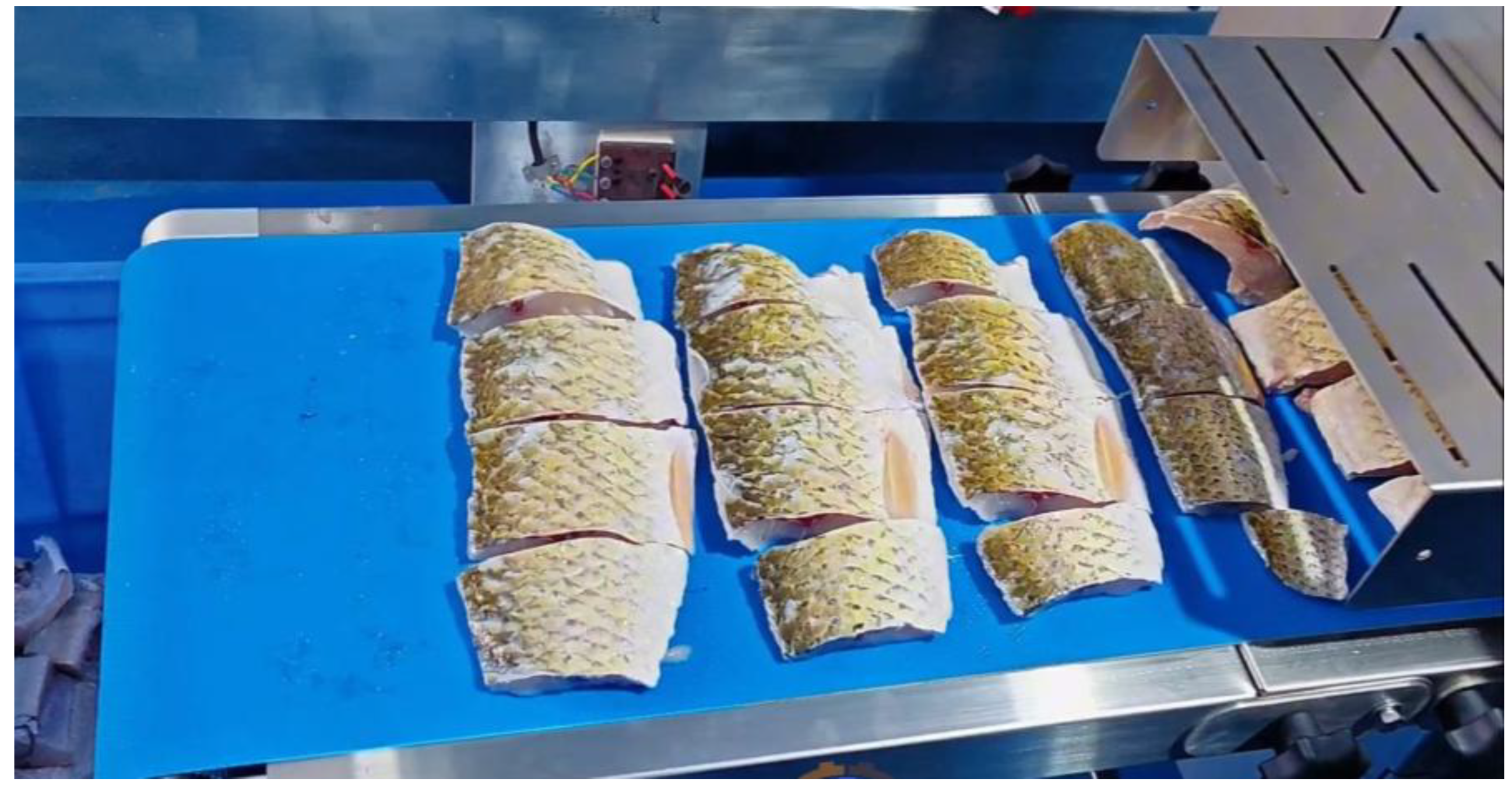
In addition, this device also underwent a test for its ability to handle a large number of fish. The results showed that during a 5 h cutting test, the weight of the grass carp processed reached 1000 kg. Therefore, it was concluded that the average processing capacity of this device is 200 kg per hour. The results are shown in Figure 11. It can be seen that the cutting efficiency has significantly improved, the cutting accuracy has increased, and the integrity of the cutting surface is high. At the same time, based on the size of the fish body, the cutting force can be automatically adjusted in real time through pressure sensors to avoid damage to the meat, enabling the fully automatic segmental cutting of different forms of aquatic products. This has achieved the expected results and will undoubtedly become a key device for the intelligent upgrade of modern aquatic products.
At present, there are still significant gaps in the research on the automated cutting device for grass carp: Firstly, most existing devices focus on grass material cutting, while there is insufficient research on the dedicated equipment for fish processing; secondly, the mechanical structure design places more emphasis on the realization of basic functions, lacking an in-depth optimization of cutting accuracy and fish body integrity. Designing similar machines should adopt a modular technology route. For example, referring to the functional decomposition method of leaf and vegetable harvesters, the device can be divided into independent modules such as transportation, positioning, and cutting, and three-dimensional modeling and simulation verification can be conducted using SolidWorks. The innovative contribution of this device lies in the following: for the first time, the pneumatic push and rotating knife frame technology has been applied to the aquatic product processing field. Its surface damage rate of 4.2% has filled the industry gap, providing a new paradigm for the precise design in the field of food machinery.

5. Conclusions

In this paper, an automatic cutting device for grass carp was designed by the SolidWorks software, and a prototype was manufactured based on the optimized structure. The cutting of the fish body was also tested and analyzed. The main specific conclusions are as follows:
(1)
The optimized cutting scheme was designed using the SolidWorks software after comparing two cutting schemes, and the automatic clamping module, conveying module, and pushing module schemes were also designed.
(2)
The key components inside the device were designed and analyzed structurally, and a three-dimensional model of the automatic grass carp cutting device was constructed. A prototype was manufactured.
(3)
The prototype was used to conduct cutting tests on the grass carp. The results showed that the cutting rate was 200 kg/h, and the surface damage rate was less than 5%, achieving the expected cutting effect.
However, the design of this device also has some limitations. For instance, the existing trajectory design for the cutting tools did not consider the tissue differences between cartilaginous fish (such as rays) and bony fish, which may lead to differences in the cell damage rate of the section exceeding industry standards. The reduction of carbon emissions lacks a full life cycle assessment (LCA). The energy consumption of the high-speed servo system may offset the environmental benefits of intermittent operation. No live struggle compensation mechanism was set up. The current prototype machine can process 200 kg/h, which cannot match the industrial-level production line (requiring ≥800 kg/h). There is a “lab-to-factory” gap. The biomimetic blade tool uses special alloys, with a single set cost being 3.2 times that of traditional equipment. The investment return period calculation is missing. Finally, the new regulation of the European Union (EU 2025/17 [42]) requires aquatic product processing equipment to be equipped with an AI traceability module. The current design does not reserve interfaces, etc.
In the future, the fish body automatic cutting device will deeply integrate artificial intelligence and image processing technology. It will precisely locate the cutting path through real-time visual recognition, significantly improving processing accuracy and efficiency. At the same time, it will integrate an intelligent water circulation system to filter, purify, and recycle the water used in the processing, significantly reducing resource consumption and environmental pollution.

Supplementary Materials

The following supporting information can be downloaded at https://www.mdpi.com/article/10.3390/machines13121081/s1, Video S1: transmission process.

Author Contributions

Conceptualization, investigation, data curation, methodology, formal analysis, and writing—original draft, X.C.; supervision, project administration, funding acquisition, and writing—review and editing, J.C.; validation, resources, Y.W. All authors have read and agreed to the published version of the manuscript.

Funding

This study is supported by the Science and Technology Project of the Science and Technology Department of Hubei Province (No. 2023BBB096).

Data Availability Statement

The original contributions presented in the study are included in the article; further inquiries can be directed to the corresponding author.

Conflicts of Interest

The authors declare no conflicts of interest.

References

  1. Bjørlykhaug, E.; Egeland, O. Vision system for quality assessment of robotic cleaning of fish processing plants using CNN. IEEE Access 2019, 7, 71675–71685. [Google Scholar] [CrossRef]
  2. Hlavač, L.M. Application of water jet description on the descaling process. Int. J. Adv. Manuf. Technol. 2015, 80, 721–735. [Google Scholar] [CrossRef]
  3. Sampels, S. The effects of processing technologies and preparation on the final quality of fish products. Trends Food Sci. Technol. 2015, 44, 131–146. [Google Scholar] [CrossRef]
  4. Xu, W.; He, Y.; Li, J.; Zhou, J.; Xu, E.; Wang, W.; Liu, D. Robotization and intelligent digital systems in the meat cutting industry: From the perspectives of robotic cutting, perception, and digital development. Trends Food Sci. Technol. 2023, 135, 234–251. [Google Scholar] [CrossRef]
  5. Yi, L.; Wang, W.; Diao, Y.; Yi, S.; Shang, Y.; Ren, D.; Ge, K.; Gu, Y. Recent advances of artificial intelligence in quantitative analysis of food quality and safety indicators: A review. Trends Anal. Chem. 2024, 180, 117944. [Google Scholar] [CrossRef]
  6. Xu, W.; Wang, J.; Deng, Y.; Li, J.; Yan, T.; Zhao, S.; Yang, X.; Xu, E.; Wang, W.; Liu, D. Advanced cutting techniques for solid food: Mechanisms, applications, modeling approaches, and future perspectives. Compr. Rev. Food Sci. Food Saf. 2022, 21, 1568–1597. [Google Scholar] [CrossRef] [PubMed]
  7. ISO 4833-1:2013; Microbiology of the Food Chain—Horizontal Method for the Enumeration of Microorganisms—Part 1: Colony Count at 30 °C by the Pour Plate Technique. International Organization for Standardization (ISO): Geneva, Switzerland, 2013.
  8. Yuan, S.; Xu, J.; Yuan, H.; Ku, J.; Liu, Z. Design and Testing of a Fully Automatic Aquatic Plant Combining Machine for Crab Farming. Machines 2024, 12, 639. [Google Scholar] [CrossRef]
  9. Wu, H.; Luo, N.; Wang, C. Study on control strategy of the rotary synchronous fixed-length cutting system. J. Vibroeng. 2013, 15, 713–725. [Google Scholar]
  10. Komlatsky, V.I.; Podoinitsyna, T.A.; Verkhoturov, V.V.; Kozub, Y.A. Automation technologies for fish processing and production of fish products. J. Phys. Conf. Ser. 2019, 1399, 044050. [Google Scholar] [CrossRef]
  11. Mainali, S.; Li, C. A robotic fish processing line enhanced by machine learning. Aquac. Eng. 2025, 108, 102481. [Google Scholar] [CrossRef]
  12. Fu, J.; He, Y.; Cheng, F. Intelligent cutting in fish processing: Efficient, high-quality, and safe production of fish products. Food Bioprocess Technol. 2024, 17, 828–849. [Google Scholar] [CrossRef]
  13. Duan, M.; Zhu, Z.; Pi, H.; Chen, J.; Cai, J.; Wu, Y. Mechanistic Insights and Analytical Advances in Food Antioxidants: A Comprehensive Review of Molecular Pathways, Detection Technologies, and Nutritional Applications. Antioxidants 2025, 14, 438. [Google Scholar] [CrossRef] [PubMed]
  14. Huang, L.Y.; Chen, Z.S. Effect of technological parameters on hydrodynamic performance of ultra-high-pressure water-jet nozzle. Appl. Ocean Res. 2022, 129, 103410. [Google Scholar] [CrossRef]
  15. Perianu, I.A.; Murariu, A.C.; Botila, L.N.; Marin-Corciu, M.; Duma, I.; Baeră, C. Advancements in Abrasive Waterjet Cutting Technologies: A Comprehensive Overview and Future Prospects in the Manufacturing Industry. Key Eng. Mater. 2024, 996, 77–86. [Google Scholar] [CrossRef]
  16. Ma, K.; Zhang, J.; Feng, P.; Yu, D.; Wu, Z. Modeling and fitting of an ultrasonic straight-blade cutting system. Int. J. Adv. Manuf. Technol. 2021, 112, 833–843. [Google Scholar] [CrossRef]
  17. Vasilyev, A.M. Deep processing-the main direction in enhancing the efficiency of fish utilization. Ekon. I Sotsialnye Peremeny 2013, 29, 79. [Google Scholar]
  18. Chen, J.S.; Chen, J.B.; Shi, Q.Y.; Wang, Y.T.; Xia, X.Z.; Li, R.D. Microstructure and high-temperature performance of heat-resistant Al− Fe− Mn alloy prepared by laser powder bed fusion. Trans. Nonferrous Met. Soc. China 2025, 35, 2183–2200. [Google Scholar] [CrossRef]
  19. Liao, I.C.; Hsu, Y.K.; Lee, W.C. Technical innovations in eel culture systems. Rev. Fish. Sci. 2002, 10, 433–450. [Google Scholar] [CrossRef]
  20. Kapłonek, W.; Nadolny, K.; Zieliński, B.; Plichta, J.; Pimenov, D.Y.; Sharma, S. The role of observation–Measurement methods in the surface characterization of X39Cr13 stainless-steel cutting blades used in the fish processing industry. Materials 2020, 13, 5796. [Google Scholar] [CrossRef]
  21. Liu, Z.; Liao, Z.; Wang, D.; Wang, C.; Song, C.; Li, H.; Liu, Y. Recent advances in soft biological tissue manipulating technologies. Chin. J. Mech. Eng. 2022, 35, 89. [Google Scholar] [CrossRef]
  22. Skjoldebrand, C. Food-processing equipment. In Handbook of Food Factory Design; Springer: New York, NY, USA, 2013; pp. 51–77. [Google Scholar]
  23. De Silva, C.W.; Wickramarachchi, N. An innovative machine for automated cutting of fish. IEEE/ASME Trans. Mechatron. 2002, 2, 86–98. [Google Scholar] [CrossRef]
  24. Li, Q.; Ma, H.; Min, W.; Wang, Y.; Zhao, R.; Zhou, Y.; Tan, Y.; Luo, Y.; Hong, H. Recent advances in fish cutting: From cutting schemes to automatic technologies and internet of things innovations. Compr. Rev. Food Sci. Food Saf. 2024, 23, e70039. [Google Scholar] [CrossRef]
  25. Bibwe, B.R.; Hiregoudar, S.; Nidoni, U.R.; Anantachar, M.; Shrestha, B. Development of a meat-bone separator for small-scale fish processing. J. Food Sci. Technol. 2013, 50, 763–769. [Google Scholar] [CrossRef] [PubMed]
  26. Cheng, J.H.; Sun, D.W.; Han, Z.; Zeng, X.A. Texture and structure measurements and analyses for evaluation of fish and fillet freshness quality: A review. Compr. Rev. Food Sci. Food Saf. 2014, 13, 52–61. [Google Scholar] [CrossRef] [PubMed]
  27. Lee, J.H.; Kang, S.I.; Mansoor, S.; Lee, I.; Kim, D.Y.; Kim, Y.Y.; Park, Y.; Sohn, J.H.; Bashir, K.M.I.; Choi, J.S. Development and process optimization of a steamed fish paste cake prototype for room temperature distribution. Processes 2024, 12, 795. [Google Scholar] [CrossRef]
  28. Aly, B.A.; Low, T.; Long, D.; Brett, P.; Baillie, C. Tactile sensing for tissue discrimination in robotic meat cutting: A feasibility study. J. Food Eng. 2024, 363, 111754. [Google Scholar] [CrossRef]
  29. Mu, X.; Xue, Y.; Jia, Y.B. Robotic cutting: Mechanics and control of knife motion. In Proceedings of the 2019 International Conference on Robotics and Automation (ICRA), Montreal, QC, Canada, 20–24 May 2019; pp. 3066–3072. [Google Scholar]
  30. Shaw, K.P.; Chung, J.H.; Chung, F.C.; Tseng, B.Y.; Pan, C.H.; Yang, K.T.; Yang, C.P. A method for studying knife tool marks on bone. J. Forensic Sci. 2011, 56, 967–971. [Google Scholar] [CrossRef]
  31. Biallas, G.H. High Force Spring Clamp System; Hyperboloid LLC: Yorktown, VA, USA, 2021. [Google Scholar]
  32. ISO 22000:2018; Food Safety Management Systems—Requirements for Any Organization in the Food Chain. International Organization for Standardization (ISO): Geneva, Switzerland, 2018.
  33. Chen, J.; Liu, Y.; Yang, J.; He, L.; Tang, H.; Li, X. A review of development and applications of SiC power devices in packaging and interconnect technology. Solder. Surf. Mt. Technol. 2025, 37, 76–83. [Google Scholar] [CrossRef]
  34. El-Elamy, M.I. Improving the Dynamic Performance of the Crank-Rocker Mechanism Using Composite Links. ERJ. Eng. Res. J. 2023, 46, 471–484. [Google Scholar] [CrossRef]
  35. Reytskiy, M.; Kovalenko, M.; Tymoshchuk, O. Selection and Calculation of Servo Motors for CNC. Наукoвий журнал «Енергетика: екoнoміка, технoлoгії, екoлoгія» 2021, 2. [Google Scholar]
  36. Busch-Vishniac, I.J. Electromechanical Sensors and Actuators; Springer Science & Business Media: Berlin/Heidelberg, Germany, 1998. [Google Scholar]
  37. Chen, J.; Chen, J.; Wang, H.; He, L.; Huang, B.; Dadbakhsh, S.; Bartolo, P. Fabrication and development of mechanical metamaterials via additive manufacturing for biomedical applications: A review. Int. J. Extrem. Manuf. 2025, 7, 012001. [Google Scholar] [CrossRef]
  38. Shi, Q.; Chen, J.; Chen, J.; Liu, Y.; Wang, H. Application of additively manufactured bone scaffold: A systematic review. Biofabrication 2024, 16, 022007. [Google Scholar] [CrossRef]
  39. Hu, M.; Zhi, S.; Chen, J.; Li, R.; Liu, B.; He, L.; Yang, H.; Wang, H. Restraint of intermetallic compound and improvement of mechanical performance of Ti/Al dissimilar alloy by rotary friction welding based on laser powder bed fusion. J. Manuf. Process. 2024, 131, 440–454. [Google Scholar] [CrossRef]
  40. Wang, Y.; Guo, W.; Li, H.; Xie, Y.; Shi, J.; Liang, Z.; Han, P.; Li, S.; Zhang, H. Nano-scale microstructural evolution and mechanical property enhancement mechanism during crack inhibition in nickel-based superalloys fabricated by laser powder bed fusion. Addit. Manuf. 2025, 100, 104685. [Google Scholar] [CrossRef]
  41. Liao, Z.; La Monaca, A.; Murray, J.; Speidel, A.; Ushmaev, D.; Clare, A.; Axinte, D.; M’Saoubi, R. Surface integrity in metal machining-Part I: Fundamentals of surface characteristics and formation mechanisms. Int. J. Mach. Tools Manuf. 2021, 162, 103687. [Google Scholar] [CrossRef]
  42. Commission Regulation (EU) 2025/1090; Amending REACH Annex XVII regarding DMAC and NEP. Publications Office of the European Union: Luxembourg, Luxembourg, 2025.
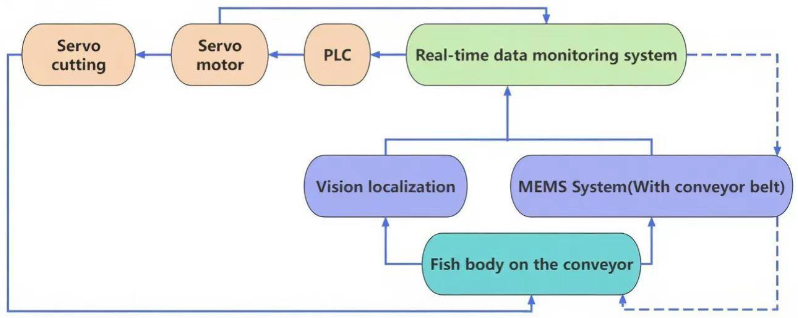
Figure 1. A flowchart of the control system for the automated cutting device.
Machines 13 01081 g001
Figure 2. A schematic diagram of the cut-clamping module 1.
Machines 13 01081 g002
Figure 3. German MATRIX fixture 2.
Machines 13 01081 g003
Figure 4. A schematic diagram of the clamping of the flexible clamping sub-module 3.
Machines 13 01081 g004
Figure 5. A three-dimensional view of the transmission module 4.
Machines 13 01081 g005
Figure 6. The core structure of the transmission structure 5.
Machines 13 01081 g006
Figure 7. Design of transmission module: (a) initial state, (b) end state.
Machines 13 01081 g007
Figure 8. An overall three-dimensional view of the push module 6.
Machines 13 01081 g008
Figure 9. A schematic diagram of an automated cutting device.
Machines 13 01081 g009
Figure 10. The design schematic diagram of the cutting module: (a) retracted state; (b) cutting state.
Machines 13 01081 g010
Figure 11. A physical diagram of the automated cutting and segmenting device for aquatic products.
Machines 13 01081 g011
Table 1. Testing of surface damage rate for grass carp.
GroupNumber
(Piece)
Speed
(Fish/h)
Fish Body
Surface Area (cm2)
Damage Area (cm2)The Damage Rate (%)
1100200200.763.8
2100250251.0754.3
3100300301.354.5
Disclaimer/Publisher’s Note: The statements, opinions and data contained in all publications are solely those of the individual author(s) and contributor(s) and not of MDPI and/or the editor(s). MDPI and/or the editor(s) disclaim responsibility for any injury to people or property resulting from any ideas, methods, instructions or products referred to in the content.