Abstract
The paper highlights that hydraulic systems are widely used in various machine applications. Among the evaluation criteria for these systems, the noise-related criterion is also considered. This criterion also applies to micro-hydraulic systems as the permissible level of noise emitted into the environment is linked to the installed power, which in micro-hydraulic systems is at least an order of magnitude lower than in conventional hydraulic systems. Failure to comply with EU ambient noise emission standards may result in the machine not being approved for use. It is therefore important to identify noise sources and minimize them. It has been noted that, in hydraulic systems, the primary source of noise is pressure pulsation across a wide frequency range. Moreover, it has been pointed out that low-frequency noise and vibrations are particularly harmful to humans. Thus, pressure pulsation dampers are proposed that are effective both at specific forcing frequencies and across a wide frequency range. Experimental results of a micro-hydraulic system are presented.
Keywords:
machines; micro-hydraulic system; hydraulic damper; pressure pulsation; vibration; noise; frequency 1. Introduction
Despite increasing competition from electric and pneumatic drives, hydraulic systems continue to play a crucial role in modern engineering. Their application remains particularly strong in technological and mobile machinery [1], as well as in marine technologies [2] and aircraft [3], where reliability, compactness, and high power density are essential. In recent years, the scope of hydraulic applications has expanded beyond traditional large-scale systems. Miniaturized hydraulic drive solutions, often referred to as micro-hydraulics or small-scale hydraulics, are gaining increasing attention. These systems are increasingly integrated into compact devices and specialized applications [4], where they provide unique advantages such as the ability to transmit significant power within a limited space, precise motion control, and robustness under demanding operating conditions.
The development of such small hydraulic systems (with examples of micro-hydraulics in machines and equipment shown in Figure 1) is being driven by advancements in materials, manufacturing techniques, and microfabrication technologies. This opens new possibilities for their use in fields such as medical equipment [5], mobile and rescue equipment [6], and industrial portable tools [7], where the combination of high power output and miniaturization is becoming increasingly important.
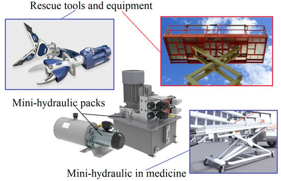
Figure 1.
Examples of micro-hydraulics in machines and equipment (partly based on [5,6,7]).
The current development of micro-hydraulics, similar to standard hydraulic technology, is linked to the proliferation of electronics and automation systems in mechanical engineering. The main advantage of hydraulic drive and lubrication systems is their extensive capability to control both the speed and power of the consumers [8]. The introduction of modern multi-level electronic systems into hydraulic systems has enabled smoother control and a significant reduction in emitted noise [9]. Additional work is currently underway to optimize the design of micro-hydraulic system components [4]. This mainly involves two directions: minimizing weight, which requires reducing overall dimensions, and reducing noise emissions. In addition, several recent research studies have analyzed the influence of design and operating parameters in micro-hydraulic systems [10,11,12,13,14]. Their introduction has significantly contributed to the adoption of central lubrication systems, as these rely on the transport of small fluid volumes. In the case of micro-hydraulic drive systems, their key advantage is the ability to transmit high power. The introduction of modern, sophisticated electronic systems into hydraulic systems has resulted in smoother control and reduced noise emissions.
However, the problem of hydraulic system noise persists, while permissible noise levels are gradually being reduced [15]. This problem is also present in micro-hydraulic systems, where noise level reduction is required by laws and regulations. Noise level is a key factor in assessing the performance and quality of machinery and equipment. With regard to noise control, the European Union’s Machinery Directive 2006/42/EC [16] requires that machines be designed and manufactured to minimize noise hazards to the lowest achievable level, in accordance with technological advancements and feasible noise-reduction methods, particularly at the source of emission. This principle is further reinforced by Directive 2000/14/EC [17], which sets limits on the permissible sound power levels of machines that emit noise into the environment.
The main sources of noise in hydraulic systems are fluid flow phenomena (e.g., cavitation) and pressure shocks [18]. Percussive pressure changes can be either impulsive (e.g., caused by water hammer or a sudden change in load on a hydraulic receiver) or periodic (e.g., resulting from pressure pulsation). Additionally, the interaction between mechanical vibrations and pressure pulsations in micro-hydraulic systems can be interpreted in two ways. In the first case, pressure pulsations in the fluid generate vibrations in system components, such as micro-lines or micro-valves [19]. In the second case, the situation is reversed—mechanical vibrations of system elements lead to pressure pulsations, which in turn actuate the control elements of micro-valves, such as distributor slides or poppet lifts [20]. In such systems, variations in fluid pressure are largely attributed to pulsations in the output of the working fluid [21], which arise from the kinematic characteristics of the displacement components of the micro-pump [22]. These output pulsations result in a periodically varying pressure distribution across the micro-hydraulic system, typically following a harmonic pattern and generating noise in the application. The frequency of this pressure pulsation matches the frequency of the pump’s output fluctuation [23,24] and additionally excites mechanical vibrations in elements such as hydraulic lines and valves, which ultimately generate most of the noise in hydraulic applications.
Excessive noise and vibration generated by machines and equipment can have harmful impacts on both the environment and humans [25]. For the human body, the most critical range is within the low-frequency spectrum, especially at frequencies below 100 Hz [26,27]. These challenges highlight the importance of research aimed at reducing noise and vibration in micro-hydraulic systems, particularly because such technologies are often used in close proximity to workers during continuous operation. The present research paper focuses on effective methods for reducing pressure pulsation amplitudes through the use of pressure pulsation dampers in micro-hydraulic systems. The conceptual and theoretical considerations were supported by experimental verification.
2. Causes of Uneven Performance of Positive Displacement Pumps
A characteristic feature of positive displacement pumps is the cyclic nature of their operation. During the rotation of the pump drive shaft, each positive displacement element completes a suction and discharge cycle. This results in an uneven transfer of fluid from the suction space to the discharge space of the pump [28,29,30]. Another phenomenon contributing to the non-uniformity of the flow rate is the often-varying speed of the fluid-displacing element. To determine the magnitude of performance pulsations, a performance non-uniformity coefficient has been introduced, which is described in detail in the literature [31,32,33]:
where Qmax—maximum instantaneous capacity; Qmin—minimum instantaneous capacity; and Qavr—average capacity.
A comparison of capacity irregularities for different types of hydraulic pumps is shown in Figure 2 below.
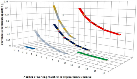
Figure 2.
Comparison of the coefficient of capacity inequality for different types of positive displacement pumps [34]: 1—Screw pump; 2—Piston pump with odd number of pistons; 3—Gear pump with internal gearing; 4—Vane pump; 5—Piston pump with an even number of pistons; 6—Gear pump with external gearing.
The analysis of the graph above shows that piston pumps with an even number of displacement elements are characterized by a higher coefficient than pumps with an odd number of displacement elements. In addition, screw pumps, piston pumps with an odd number of pistons, and gear pumps with internal gears are characterized by the lowest values of the capacity pulsation coefficient. As shown in Equation (1), the capacity non-uniformity coefficient assumes constant numerical values for the pump under consideration. As a result, performance pulsations cannot be analyzed in either the time or frequency domain.
Depending on the type of positive displacement pump (design variant), suitable mathematical models of instantaneous capacity are used to describe pump capacity pulsations as a cause of pressure pulsation. Common types of pumps include vane pumps, gear pumps, and axial or radial piston pumps. The instantaneous capacity of a single-acting vane pump, accounting for vane thickness, can be expressed as [35]:
where rl—stator turning radius; sl—blade thickness; bl—blade width; zl—number of blades; αl—centre angle of blade spacing in the rotor; and ωl—angular velocity of the pump shaft.
The mathematical model described by Equation (2) was implemented in the MATLAB R2022b environment using the Simulink 9.13 package. To perform a computer simulation of the instantaneous capacity of the vane pump, the technical documentation of the V3-63 pump, manufactured by Fabryka Elementów Hydrauliki Ponar-Wadowice S.A., Wadowice, Poland was used [36]. The simulation model makes it possible to obtain the time profile of the pump’s efficiency for user-defined design parameters (i.e., stator turning radius, blade width and thickness, number of blades) and operational parameters (i.e., drive shaft rotational speed, eccentricity value), and to record the results in the workspace for further analysis. Based on Equation (2) and the performed simulation, the instantaneous capacity waveform of the V3-63 vane pump is obtained, as shown in Figure 3a. Figure 3b presents the amplitude–frequency spectrum of the capacity pulsation.
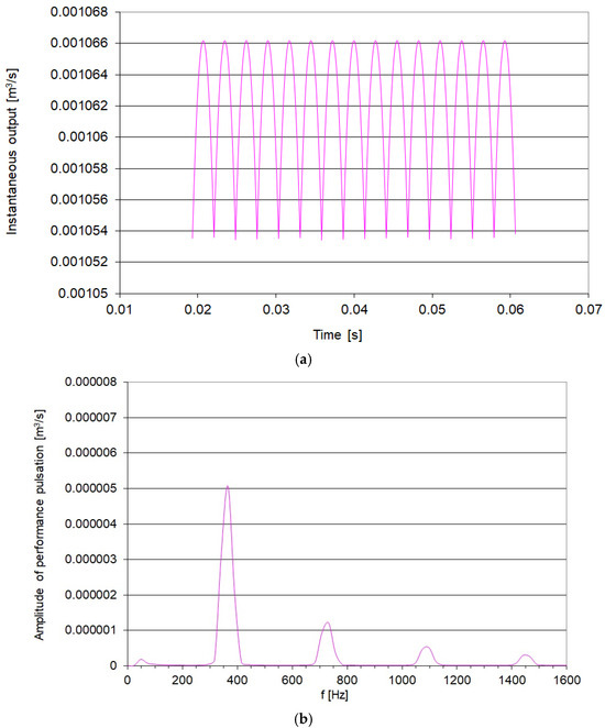
Figure 3.
Pump simulation results: (a)—Theoretical instantaneous capacity as a function of time for the V3-63 vane pump (rotational speed: 1450 rpm); (b)—Amplitude–frequency spectrum of the instantaneous capacity of the V3-63 pump.
The frequency values of the individual harmonic components of the spectrum are given by the following relationship:
where np—pump shaft speed (rpm); and K—consecutive component number (= 1, …, Ki).
The pump under consideration has 15 vanes (zl), and the pump shaft speed is 1450 rpm. As can be seen in Figure 3b, the first component of the spectrum (K = 1) occurs at a frequency of f1 = 362 Hz. Subsequent components are integer multiples of this frequency. Furthermore, due to the impedance of the hydraulic system, capacity pulsations generate pressure pulsations at corresponding frequencies.
The pressure pulsation spectrum also includes harmonics at lower frequencies. Hydraulic valves used in systems installed in mobile machinery or transport vehicles are subjected to external mechanical vibrations. The frequency range of these vibrations is wide, starting from a few hertz. The natural frequencies of the control elements of hydraulic valves fall within this range. Compared to conventional hydraulic valves, micro-hydraulic valves exhibit higher natural frequencies. If the frequencies of external mechanical vibrations are close to the natural frequencies of a hydraulic valve’s control element (e.g., spool, poppet, ball) and the direction of these vibrations coincides with the movement direction of the control element (e.g., spool movement within the valve body), vibrations of this element may be excited, leading to the appearance of additional harmonics in the pressure pulsation spectrum. Figure 4 shows the amplitude–frequency spectrum of pressure pulsations in a hydraulic system subjected to external mechanical vibration applied to a single-stage relief valve. The valve body was subjected to vibrations with frequencies ranging from 10 to 40 Hz.
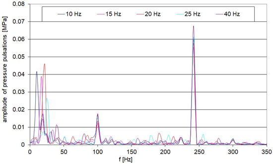
Figure 4.
Amplitude-frequency spectrum of pressure pulsations with an oscillating relief valve.
In the spectrum shown in Figure 4, the dominant harmonic component is the pressure pulsation resulting from the displacement pump’s capacity pulsation and the hydraulic system’s impedance. In this spectrum, harmonic components appear at lower frequencies, corresponding to the external mechanical vibrations acting on the relief valve body. These pulsations propagate through the hydraulic hoses and fluid to distant parts of the hydraulic system, causing vibration excitation and noise generation. Reducing the amplitudes of pressure pulsations decreases the excitations acting on hydraulic system components, thereby reducing the vibrations and noise generated by the hydraulic or micro-hydraulic system.
3. Application of a Spiral Passive Damper in a Micro-Hydraulic System
To reduce the amplitude of pressure pulsations, a passive branch-type damper can be used. In addition, to reduce the space occupied by the damper, it may be designed in a spiral shape. Compared to a straight-axis branch damper, the spiral damper has a much more compact design. Table 1 presents a comparison of the characteristics of a spiral damper and a straight-axis damper designed to reduce pressure pulsations for the same frequency. This type of damper has a selective effect, i.e., it is effective at a specific pressure pulsation frequency. The effectiveness of the damper is determined by its length: the lower the frequency to be damped, the longer the damper must be. The construction of a spiral branch damper consists of a spiral pipe of sufficient length and radius of curvature, connected perpendicularly to the main pipe and sealed at the end.

Table 1.
Comparison of selected features of spiral damper and straight-axis damper designed to reduce pressure pulsations of the same frequency.
The basis for determining the length of the spiral pipe, which forms the spiral damper, is a hydraulic transmission line model described by distributed parameters. The following equation presents a matrix transition function in operator form, taking into account the pressure p and flow rate Q at both ends of the hydraulic transmission line (the start and end of the damper), expressed as [33,37,38,39]:
where p1—pressure at the inlet of the spiral damper; p2—pressure at the outlet of the spiral damper; Q1—flow rate at the inlet of the spiral damper; Q2—flow rate at the outlet of the spiral damper; and L—length of the spiral damper.
Since the damper is a pipe closed at the end, Q2 = 0 is assumed. Multiplying the matrix expressions yields Equation (4), which defines the initial impedance of the damper as the ratio of the pressure amplitude at the inlet to the amplitude of the flow pulsation at the inlet, taking into account the quasi-estimated friction loss model [33]:
The solution of the spiral damper’s mathematical model involves determining the minimum impedance value as a function of its length for a given forcing frequency (the frequency of the pressure pulsation to be damped). The effectiveness of the designed damper also depends on the friction loss model used to determine its initial impedance. Given the typical number of pump displacement elements and the average drive shaft speed, the first harmonic component of the performance pulsation spectrum, equal to 120 Hz, was used for the calculation. The following data were used to determine the initial impedance modulus: fundamental pump harmonic f1 = 120 Hz, pipe diameter d = 4 mm, and HLP22 hydraulic oil. Figure 5 shows the initial impedance for the quasi-stationary linear (branch) damper model and the quasi-stationary spiral damper model.
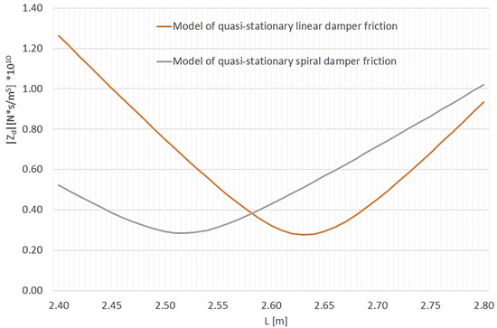
Figure 5.
Initial impedance modulus ZD of the branch damper for different friction models as a function of its length L0 (pump speed: 800 rpm; first harmonic pump pulsation frequency: 120 Hz; average pressure: 5 MPa; HLP22 hydraulic oil; oil temperature: 40 °C; oil density: ρ = 865 kg/m3; inner pipe radius: r = 2 mm; pipe spiral bend radius: R = 27 mm; wave propagation velocity: c0 = 1273 m/s).
Figure 5 shows that the spiral damper is shorter than the linear damper. For an excitation frequency of 120 Hz, the impedance minimum of the spiral damper occurs at a length of approximately 2.53 m, while for the linear damper it occurs at approximately 2.64 m.
4. Experimental Verification of the Effectiveness of the Spiral Damper
To confirm the previous considerations regarding the effectiveness of the spiral damper, experimental tests were carried out on a specially designed and manufactured micro-hydraulic test rig (a schematic of the test stand is shown in Figure 6).
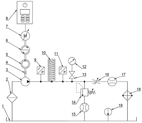
Figure 6.
Schematic diagram of the hydraulic system for pressure pulsation testing after damper installation: 1—Tank; 2—Suction filter; 3—Hydraulic pump; 4—ROTEX GS clutch, Pivexin Technology, Babice, Poland; 5—Tachometer; 6—MT5Nm-N24 torque meter, Sensor-AT, Katowice, Poland; 7—Slh80-B2/PO, electric motor (0.75 kW), Besel, Brzeg, Poland; 8—Control cabinet with inverter SS-01/07-10/PWR11, own construction; 9—Piezotronics 105C23 PCB piezoelectric pressure sensor, Depew, NY, USA; 10—Spiral pressure pulsation damper; 11—PCB Piezotronics 105C23 Piezoelectric pressure sensor, Depew, NY, USA; 12—Manometer; 13—Cut-off valve; 14—Safety valve; 15—Flow meter; 16—Adjustable throttle valve; 17—Flow meter; 18—Cooler; 19—Thermometer.
The source of the pressurised fluid flow is the positive displacement pump (3) WPH PZ3-0.6, Wytwórnia Pomp Hydraulicznych, Wrocław, Poland. The pump has 14 teeth on both the active and passive wheels, with a unit capacity of cm3/rev. To ensure adequate suction conditions, the tank (1) is installed above the pump (3). The pump’s rotary shaft speed was monitored using a tachometer (5). A pressure pulsation sensor (9) was installed on the hydraulic line downstream of the displacement pump, followed by the damper under test (10) and another pressure pulsation sensor (11) immediately downstream. A pressure gauge (12) was used to monitor average pressure. During data recording, the system’s connection to the manometer was cut off using a shut-off valve (13). The measuring system was equipped with a safety valve (14) and a flow meter (15), which was used to monitor the opening of the safety valve. The system pressure was set using a throttle valve (16). The flow rate was measured using a flow meter (17). A cooler (18) with a controller and a fan driven by an electric motor was used to stabilize the temperature of the working fluid. The motor (7) driving the displacement pump was connected to a control cabinet (8). This allowed the measuring system to adjust the pump speed.
Figure 7 shows the measuring station (test stand) where the verification measurements were carried out.
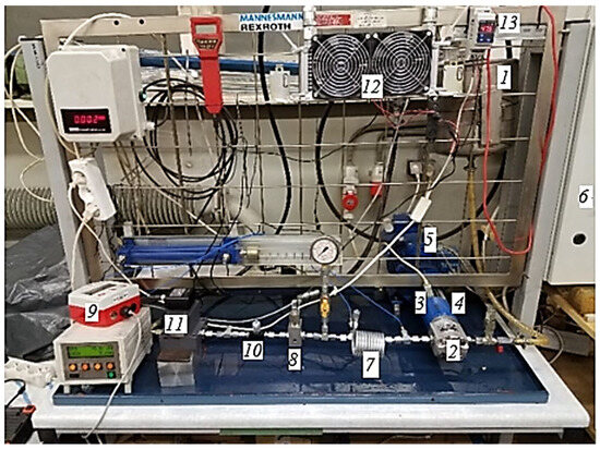
Figure 7.
Test stand: 1—Tank; 2—Gear pump WPH PZ3-0.6, Wytwórnia Pomp Hydraulicznych, Wrocław, Poland; 3—Tachometer; 4—Torque meter MT5Nm-N24, Sensor-AT, Poland; 5—Electric motor Slh80-B2/PO (0.75 kW), Besel, Brzeg, Poland; 6—Control cabinet with inverter SS-01/07-10/PWR11, own construction; 7—Spiral pressure pulsation damper; 8—Safety valve; 9—Flow meter; 10—Adjustable throttle valve; 11—Flow meter; 12—Oil cooler; 13—Thermometer.
Measurements were carried out using Piezotronics 105C23 piezoelectric PCB pressure sensors. The signal collected by the sensors was sent to a Dewesoft measurement card, where analogue-to-digital conversion and data acquisition were performed. Data processing was performed in the Microsoft Excel environment. The length of the spiral damper was varied from 2370 mm to 2860 mm in steps of 10 mm. The test bench was filled with HLP 22 oil, with a density of ρ = 865 kg/m3. Characteristic data of the damper pipe: inner radius r = 2 mm; and bend radius of the spiral R = 27 mm. Figure 8 shows an example of measurements obtained for a system without a damper, recorded downstream of the blinded location of the anticipated damper.
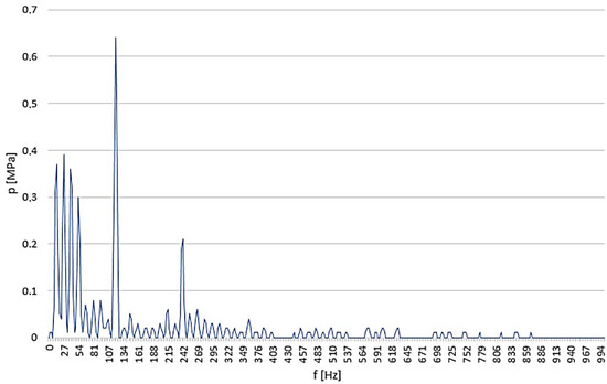
Figure 8.
Pressure pulsation measurement without a damper (f1 = 120 Hz at n = 800 rpm); oil temperature: 50 °C; average pressure: 5 MPa.
Figure 9 shows a comparison between the impedance model of a spiral damper and the measured pressure pulsations for the damper as a function of its length.
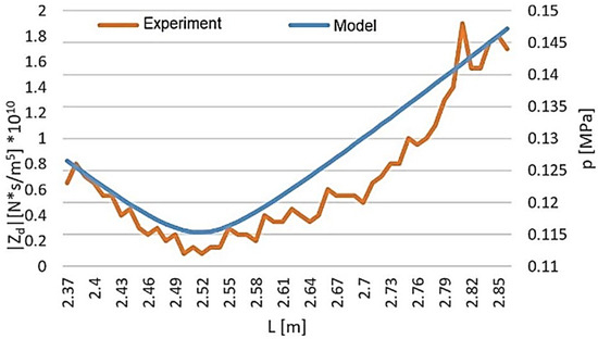
Figure 9.
Comparison of spiral damper impedance and pressure pulsation as a function of damper length (pump speed: 800 rpm; first harmonic pump pulsation frequency: 120 Hz; average pressure: 5 MPa; fluid temperature: 50 °C).
Figure 9 shows that changing the damper length for a given excitation frequency alters the damper’s impedance. For a given excitation frequency, it is possible to select a damper length that provides maximum effectiveness.
5. Reduction in Pressure Pulsations over a Wide Frequency Range
As indicated, a passive branch-type damper is effective at the selected forcing frequency. However, the pressure pulsation spectrum may contain both low- and high-frequency harmonics. In such cases, a broadband damper can be used to reduce pressure pulsations across a wide frequency range [40]. A broadband damper combines a passive branch damper with an active damper. The branch damper, with length L, reduces pressure pulsation amplitudes at higher frequencies, while the active damper reduces them at lower frequencies. The branch passive damper operates on the principle of reflection and interference between the incident and reflected waves. The active damper operates on the principle of absorbing the incoming wave. It consists of a hydropneumatic accumulator and a piston moving within a cylinder. A schematic of the broadband damper is shown in Figure 10.
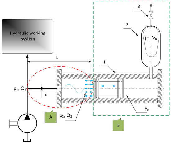
Figure 10.
Schematic of the broadband damper construction: A—Passive branch damper; B—Active damper (1—Cylinder with moving piston; 2—Hydropneumatic accumulator; 3—Accumulator charging cut-off valve).
The passive damper (part A in Figure 10), which is part of the broadband damper, is most effective when its initial impedance reaches a minimum, analogous to the spiral damper. On the other hand, the active damper (part B in Figure 10), which forms part of the broadband damper, is most effective when its natural frequency equals the forcing frequency (the frequency of the pressure pulsation to be suppressed). The selection of active damper parameters reduces to ensuring that the resonant frequency of the piston–hydropneumatic spring system equals the pressure pulsation frequency fw to be suppressed. The resonant frequency of the active damper is given by the following relation [37,40]:
where n—the polytropic exponent; F0—active surface area of the piston; pk—value of the pressure in the system; p0—value of the initial pressure of the gas in the accumulator; V0—initial volume of the gas in the accumulator; and mzr—reduced mass of the oscillating system.
6. Experimental Verification of the Effectiveness of a Broadband Damper
Experimental verification of the effectiveness of the proposed broadband damper solution was conducted on a real object: the lifting mechanism of a wheel loader boom with a micro-hydraulic system (see Figure 11). For this purpose, the system was placed in an acoustic diffusion chamber. A comparative acoustic study was carried out on the system without a damper and with a damper.
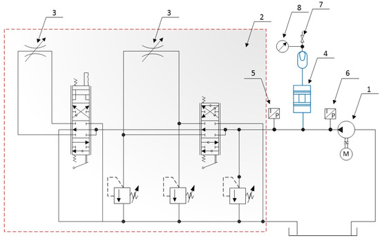
Figure 11.
Diagram of the micro-hydraulic system for lifting the loader boom with throttle valves and a damper: 1—Pump; 2—Directional control valve R1011VF1V; 3—Throttle valve; 4—Broadband damper; 5 and 6—Pressure sensors; 7—Cut-off valve; 8—Pressure gauge.
The corrected sound pressure level was recorded for the system during boom lifting at a fixed pump drive shaft speed. Two series of measurements were carried out under identical conditions: one with a damper and one without. Figure 12 shows the results of the acoustic measurements.
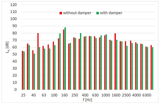
Figure 12.
Comparison of the third-order noise spectrum of the micro-hydraulic system (pump speed: n = 1000 rpm).
The results shown in Figure 12 indicate that, for most frequencies in the spectrum, noise reduction was achieved through the use of a pressure pulsation damper. The greatest noise reduction in the tested hydraulic system was observed at low frequencies of approximately 50 Hz (Figure 13). The reduction efficiency of the corrected sound pressure level LA is defined as the ratio of the amplitude LAd (system with damper) to the amplitude LAw (system without damper) at the selected frequency.
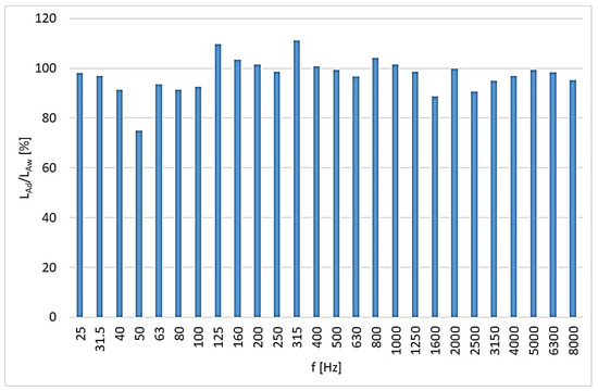
Figure 13.
Effectiveness of the broadband damper as a function of frequency.
Experimental studies have shown that the proposed broadband damper is effective over a wide frequency range and functions as an acoustic filter. The experimental results confirm that the broadband damper significantly attenuates pressure pulsations across a wide frequency range in the micro-hydraulic system. Notably, the most pronounced noise reduction occurred at lower frequencies near 50 Hz, validating the damper’s design objectives. These findings demonstrate the damper’s practical effectiveness and highlight its potential for improving acoustic performance in similar hydraulic applications.
7. Conclusions
The paper points out that an operating micro-hydraulic system is a source of vibration and noise across a wide frequency range. The main cause of noise in hydraulic systems is impact pressure variations in the working fluid, either impulsive or harmonic. Pressure pulsations can be caused by displacement pump capacity fluctuations and by external mechanical vibrations acting on hydraulic valves. The resulting pressure pulsation is characterized by a wide frequency range. The problem of noise is also significant in micro-hydraulic systems. In these systems, the limited amount of available space presents an additional constraint. A passive spiral branch damper is proposed for use in micro-hydraulic systems. The form of the initial impedance function of the damper, which determines its effectiveness, is presented. This damper has a selective effect while occupying much less space than a straight-axis damper. The branch-type spiral damper presented in this paper is most effective for the selected excitation frequency (pressure pulsation). This means that if the pressure pulsation comes from the pulsation of the displacement pump capacity, it must operate at a constant rotational speed. A broadband damper, consisting of a branch (straight-axis) passive damper and an active damper, was used for pressure pulsation and noise reduction over a wide frequency range. A condition for the effective operation of the active damper is defined. The conceptual and theoretical considerations were experimentally verified. The analytical considerations presented (Equation (5) and Figure 5) show that the spiral damper will be shorter than the linear damper. For a forcing frequency of 120 Hz, the minimum impedance of the spiral damper is at a length of approx. 2.53 m, and for the linear damper the minimum is at a length of approx. 2.64 m. The use of a broadband damper reduced the noise of the hydraulic microcircuit by 20 dB at a frequency of 50 Hz.
Author Contributions
Conceptualization, M.S. and M.K.; methodology, M.S. and K.T.; software, M.S., P.S. and K.T.; validation, M.S. and K.T.; formal analysis, M.S. and M.K.; investigation, M.S., K.T. and M.K.; resources, M.S., K.T. and P.S.; data curation, M.S., P.S. and K.T.; writing—original draft preparation, M.S., P.S. and M.K.; writing—review and editing, M.S. and M.K.; visualization, K.T. and P.S.; supervision, M.S. and M.K.; project administration, M.S. and M.K.; funding acquisition, M.S., K.T., P.S. and M.K. All authors have read and agreed to the published version of the manuscript.
Funding
This research received no external funding.
Data Availability Statement
All data included in this research are available upon request from the corresponding author.
Conflicts of Interest
The authors declare no conflicts of interest.
References
- Nisha, K.; Upadhyay, G.; Patel, B.; Choudhary, S.; Rani, V. A tractor hydraulic assisted embedded microprocessor-based penetrometer for soil compaction measurement. J. Terramech. 2023, 110, 1–12. [Google Scholar] [CrossRef]
- Wang, Y.; Zhai, B.; Chen, Y.; Huo, L.; Du, L.; Liu, T.; Zhang, A.; Zhang, Q. Design and performance research of water–glycol deep-sea valve-controlled hydraulic cylinder system based on on-line regulation of ambient pressure. Ocean Eng. 2024, 313, 119492. [Google Scholar] [CrossRef]
- Liu, X.; Li, D.; Qi, P.; Qiao, W.; Shang, Y.; Jiao, Z. A local resistance coefficient model of aircraft hydraulics bent pipe using laser powder bed fusion additive manufacturing. Exp. Therm. Fluid Sci. 2023, 147, 110961. [Google Scholar] [CrossRef]
- Jianying, L.; Guodong, Q.; Shuai, X.; Chen, P. Review of Development and Application of Main Micro-hydraulic Components and Key Technologies. Recent Pat. Eng. 2025, 19, e110923220923. [Google Scholar] [CrossRef]
- JWF Technologies. Industries Medical Web-Page. Available online: https://www.jwftechnologies.com/industries/medical (accessed on 20 September 2025).
- HURST Jaws of Life®. Web-Page. Available online: https://www.jawsoflife.com/ (accessed on 20 September 2025).
- HAVE Hydraulics. Mini Hydraulic Power Packs Web-Page. Available online: https://www.hawe.com/products/mini-hydraulics/ (accessed on 20 September 2025).
- Salam, M.A. Fundamentals of Pneumatics and Hydraulics; Springer: Singapore, 2022; 403p. [Google Scholar] [CrossRef]
- Fan, Q.; Zhang, J.; Li, R.; Fan, T. Review of Research on Hydrostatic Transmission Systems and Control Strategies. Processes 2025, 13, 317. [Google Scholar] [CrossRef]
- Zhou, Y.; Liu, J.; Yan, J.; Zhu, T.; Guo, S.; Li, S.; Li, T. Standing Air Bubble-Based Micro-Hydraulic Capacitors for Flow Stabilization in Syringe Pump-Driven Systems. Micromachines 2020, 11, 396. [Google Scholar] [CrossRef]
- Zhu, Y.; Volder, M.D.; Yoshida, K.; Kim, J.W. Next-generation EHD micropumps with space-efficient MEMS-fabricated needle and ring electrode arrays. Sens. Actuators A Phys. 2025, 396, 117160. [Google Scholar] [CrossRef]
- Kedzierski, J.; Chea, H. Multilayer microhydraulic actuators with speed and force configurations. Microsyst. Nanoeng. 2021, 7, 22. [Google Scholar] [CrossRef]
- Roberts, D.; Li, H.; Steyn, J.L.; Turner, K.; Mlcak, R.; Saggere, L.; Spearing, S.M.; Schmidt, M.; Hagood, N. A high-frequency, high-stiffness piezoelectric actuator for microhydraulic applications. Sens. Actuators A Phys. 2002, 97, 620–631. [Google Scholar] [CrossRef]
- Hufenus, R.; Hofmann, J.; Gooneie, A. Fine liquid-core polymer fibers for microhydraulic applications: A versatile process design. Mater. Des. 2022, 222, 111077. [Google Scholar] [CrossRef]
- Padovani, D.; Dimitriou, P.; Minav, T. Challenges and solutions for designing Energy-Efficient and Low-Pollutant Machines in Off-Road hydraulics. Energy Convers. Manag. X 2024, 21, 100526. [Google Scholar] [CrossRef]
- Directive 2006/42/EC of the European Parliament and of the Council of 17 May 2006 on Machinery, and Amending Directive 95/16/EC. 2006. Available online: https://eur-lex.europa.eu/legal-content/EN/TXT/PDF/?uri=CELEX:32006L0042 (accessed on 20 September 2025).
- Directive 2000/14/EC of the European Parliament and of the Council of 8 May 2000 on the Approximation of the Laws of the Member States Relating to the Noise Emission in the Environment by Equipment for Use Outdoors. 2000. Available online: https://eur-lex.europa.eu/legal-content/EN/TXT/PDF/?uri=CELEX:32000L0014 (accessed on 20 September 2025).
- Ren, X.; Guo, Q.; Li, T.; Jiang, D.; Shi, Y. Fault detection and tolerant control with a variable-bandwidth extended state observer for electro-hydraulic servo systems with lumped disturbance and measurement noise. ISA Trans. 2025, 162, 287–300. [Google Scholar] [CrossRef] [PubMed]
- Stosiak, M.; Karpenko, M.; Skačkauskas, P.; Deptuła, A.; Krawczyk, J. Vibrations of Micro-hydraulic Pipes Induced by Pulsatile Fluid Flow. In TRANSBALTICA XIV: Transportation Science and Technology; TRANSBALTICA 2023. Lecture Notes in Intelligent Transportation and Infrastructure; Springer: Cham, Switzerland, 2024; pp. 79–90. [Google Scholar] [CrossRef]
- Towarnicki, K. Disadvantageous effects of vibrations on the micro-hydraulic relief valve: Experimental approach. Aviation 2025, 29, 55–60. [Google Scholar] [CrossRef]
- Pourjafar-Chelikdani, M.; Lavaf, A.; Taghilou, B.; Almasi, S.; Kowsar, S.; Najafi-Astmal, H.; Mahdavi Nejad, A.; Sadeghy, K. On the use of viscous micropumps for the transport of yield-stress liquids in microfluidic systems. J. Non-Newton. Fluid Mech. 2022, 308, 104894. [Google Scholar] [CrossRef]
- Luo, X.; Yang, L.; Cui, Y. Micropumps: Mechanisms, fabrication, and biomedical applications. Sens. Actuators A Phys. 2023, 363, 114732. [Google Scholar] [CrossRef]
- Zhang, Z.; Cao, S.; Wang, H.; Luo, X.; Deng, J.; Zhu, Y. The approach on reducing the pressure pulsation and vibration of seawater piston pump through integrating a group of accumulators. Ocean Eng. 2019, 173, 319–330. [Google Scholar] [CrossRef]
- Klaerner, M.; Kroll, L.; Metzler, D.; Eberl, R.; De Lima, L.Z.; Kloft, P.; Kusserow, T.; Sander, M.; Thielecke, F. Reduction of fluid noise in modern aircraft hydraulics by integrated broadband attenuators. CEAS Aeronaut. J. 2025, 16, 417–425. [Google Scholar] [CrossRef]
- Khan, D.; Burdzik, R. Measurement and analysis of transport noise and vibration: A review of techniques, case studies, and future directions. Measurement 2023, 220, 113354. [Google Scholar] [CrossRef]
- Karpenko, M.; Prentkovskis, O.; Skačkauskas, P. Analysing the impact of electric kick-scooters on drivers: Vibration and frequency transmission during the ride on different types of urban pavements. Eksploat. I Niezawodn. Maint. Reliab. 2025, 27, 199893. [Google Scholar] [CrossRef]
- Araújo Alves, J.; Neto Paiva, F.; Torres Silva, L.; Remoaldo, P. Low-Frequency Noise and Its Main Effects on Human Health—A Review of the Literature between 2016 and 2019. Appl. Sci. 2020, 10, 5205. [Google Scholar] [CrossRef]
- Josifovic, A.; Roberts, J.; Corney, J.; Davies, B.; Shipton, Z. Reducing the environmental impact of hydraulic fracturing through design optimisation of positive displacement pumps. Energy 2016, 115, 1216–1233. [Google Scholar] [CrossRef]
- Yazar, M. Comparative efficiency and performance analysis of spur gear and non-circular (square) gear hydraulic pumps. Flow Meas. Instrum. 2025, 102, 102817. [Google Scholar] [CrossRef]
- Zhang, J.; Yin, W.; Shen, S.; Wang, K.; Shi, J.; Li, Y. Influence of piston chamber volume on fluid pulsation and acoustic behavior in axial piston pumps. Flow Meas. Instrum. 2026, 107, 103089. [Google Scholar] [CrossRef]
- Volk, M. Pump Characteristics and Applications; CRC Press: Boca Raton, FL, USA, 2013; 516p, ISBN 9781466563087. [Google Scholar]
- Williams, L. Fundamentals of External Gear Pump Design; NRL/8230/FR--2022/3; Naval Research Laboratory: Washington, DC, USA, 2022; 120p, Available online: https://apps.dtic.mil/sti/trecms/pdf/AD1169714.pdf (accessed on 20 September 2025).
- Towarnicki, K. Design Method for Branch-Type Spiral Damper to Reduce Pressure Pulsations in Hydraulic Systems. Ph.D. Thesis, Wrocław University of Science and Technology, Wrocław, Poland, 2024; 171p. (In Polish). [Google Scholar]
- Stosiak, M.; Karpenko, M. Dynamics of Machines and Hydraulic Systems. In Mechanical Vibrations and Pressure Pulsations; Springer: Cham, Switzerland, 2024; 179p, ISBN 978-3-031-55527-5. [Google Scholar] [CrossRef]
- Stryczek, S. Napęd Hydrostatyczny; Wydawnictwo Naukowe PWN: Warszawa, Poland, 2016; 448p, ISBN 9788301189570. (In Polish) [Google Scholar]
- Ponar-Wadowice. Web-Page Catalogue. Available online: https://www.ponar-wadowice.pl/typ/156-pompy-pompy-hydrauliczne-lopatkowe-zmiennej-wydajnosci-v3 (accessed on 20 September 2025).
- Kudźma, Z. Pressure Fluctuation and Noise Damping in Hydraulic Systems in Transient and Steady States; Oficyna Wydawnicza Politechniki Wrocławskiej: Wrocław, Poland, 2012; 261p, ISBN 978-83-7493-681-1. (In Polish) [Google Scholar]
- Hu, J.; Yang, J.; Zeng, W.; Zhao, Z.; Yang, J. Hydraulic interaction of two parallel pump-turbines in constant-speed oscillation: Measurement, simulation, and sensitivity analysis. Renew. Energy 2021, 176, 269–279. [Google Scholar] [CrossRef]
- Stosiak, M.; Bury, P.; Karpenko, M. The influence of hydraulic hose length on dynamic pressure waveforms including wave phenomena. Sci. Rep. 2025, 15, 31548. [Google Scholar] [CrossRef]
- Stosiak, M.; Yatskiv, I.; Prentkovskis, O.; Karpenko, M. Reduction of Pressure Pulsations over a Wide Frequency Range in Hydrostatic Systems. Machines 2025, 13, 25. [Google Scholar] [CrossRef]
Disclaimer/Publisher’s Note: The statements, opinions and data contained in all publications are solely those of the individual author(s) and contributor(s) and not of MDPI and/or the editor(s). MDPI and/or the editor(s) disclaim responsibility for any injury to people or property resulting from any ideas, methods, instructions or products referred to in the content. |
© 2025 by the authors. Licensee MDPI, Basel, Switzerland. This article is an open access article distributed under the terms and conditions of the Creative Commons Attribution (CC BY) license (https://creativecommons.org/licenses/by/4.0/).