1. Introduction
The line-start permanent-magnet (LSPM) motor has attracted increasing attention as a promising solution for high-efficiency industrial drives [
1,
2,
3,
4]. The motor consists of a squirrel-cage winding and permanent magnets (PMs) embedded in the rotor. The cage winding enables direct-on-line starting in the same manner as an induction motor. The PMs provide synchronous operation with high efficiency and power factor, which are characteristic of PM synchronous motors. These hybrid characteristics make the LSPM motor suitable for applications that require direct-on-line operation and demand improved energy efficiency.
Despite these advantages, LSPM motors still face several challenges that limit their widespread industrial adoption. Typical issues include limited starting torque, unstable synchronization under heavy load, and the complexity of rotor design that must accommodate both cage bars and PMs. To address these challenges, many studies have investigated the design and optimization of LSPM motors [
3], focusing on analytical and experimental approaches such as rotor design [
5,
6,
7,
8], operational characteristics [
9,
10,
11,
12], and manufacturing processes [
13,
14,
15]. Most of these studies have concentrated on interior permanent-magnet (IPM) rotor configurations. However, IPM rotors involve complicated structures with cage bars, end rings, flux barriers, and embedded PMs. The manufacturing process is particularly difficult because high-temperature die casting can damage magnet properties. Post-casting insertion and magnetization of PMs require special techniques and equipment [
13,
14,
15]. Although valuable insights have been gained, existing studies often rely on complex optimization procedures, and practical rotor design guidelines that can be applied in a straightforward manner remain limited.
A surface permanent-magnet (SPM) line-start motor has been investigated as an alternative to the IPM structure [
16,
17]. Because the PMs are mounted on the rotor surface close to the stator windings, the magnet torque becomes relatively large. The SPM configuration also offers advantages in terms of ease of manufacturing and cooling performance. It has been reported that a well-designed SPM motor can achieve good overall performance, except for limited asynchronous torque [
16]. A modified rotor topology with an additional lower slot beneath the PMs, in addition to the conventional upper slot, has also been proposed to improve the starting capability [
17].
Based on this background, a line-start consequent-pole SPM motor has been proposed for pump and fan applications [
18,
19,
20]. In this configuration, the number of PMs is reduced to half that of a conventional SPM motor, while maintaining the same total magnet volume. The starting performance is improved due to the larger number of cage bars, although the synchronous torque and efficiency may be slightly lower than those of conventional IPM and SPM designs because of a reduced fundamental flux component. Nevertheless, the rotor structure remains simple and highly manufacturable. The die-casting process is straightforward because a foundry core can be placed at the PM positions, allowing easy insertion of the PMs afterward. In addition, unmagnetized PMs can be mounted and subsequently magnetized without difficulty. These features reduce manufacturing time and can improve the machining accuracy of the rotor surface compared with conventional SPM rotors. Previous finite element method (FEM) analyses have demonstrated that the proposed motor achieves favorable steady-state torque–slip characteristics and smooth transient starting behavior [
18,
19]. In this paper, a prototype of the line-start consequent-pole SPM motor is manufactured, and its starting and steady-state characteristics are experimentally evaluated [
20]. Furthermore, a rotor design method is investigated to improve the torque and efficiency characteristics. In contrast to our previous works [
18,
19,
20], which mainly focused on the fundamental analysis and basic experimental verification of the consequent-pole configuration, this study extends the investigation by providing a comprehensive discussion on the motor performance under line-start operation and introducing simplified rotor design strategies for performance improvement. The previously reported data are reanalyzed and discussed in greater depth to provide more appropriate and comprehensive interpretations of the motor performance. This approach allows the clarification of the key mechanisms affecting the torque, efficiency, and flux distribution, which were not sufficiently addressed in the previous publications [
18,
19,
20].
2. Line-Start Consequent-Pole SPM Motor
This section introduces the concept and design of a line-start consequent-pole SPM motor. Three SPM configurations are compared to clarify the differences in electromagnetic characteristics and rotor structures. Based on this comparison, a consequent-pole SPM design previously proposed in our earlier works [
18,
19,
20] is adopted as a practical alternative to IPM structures. The configuration of the analyzed motor is described, and an FEM analysis is carried out to evaluate its electromagnetic characteristics.
2.1. Comparison of SPM Configurations
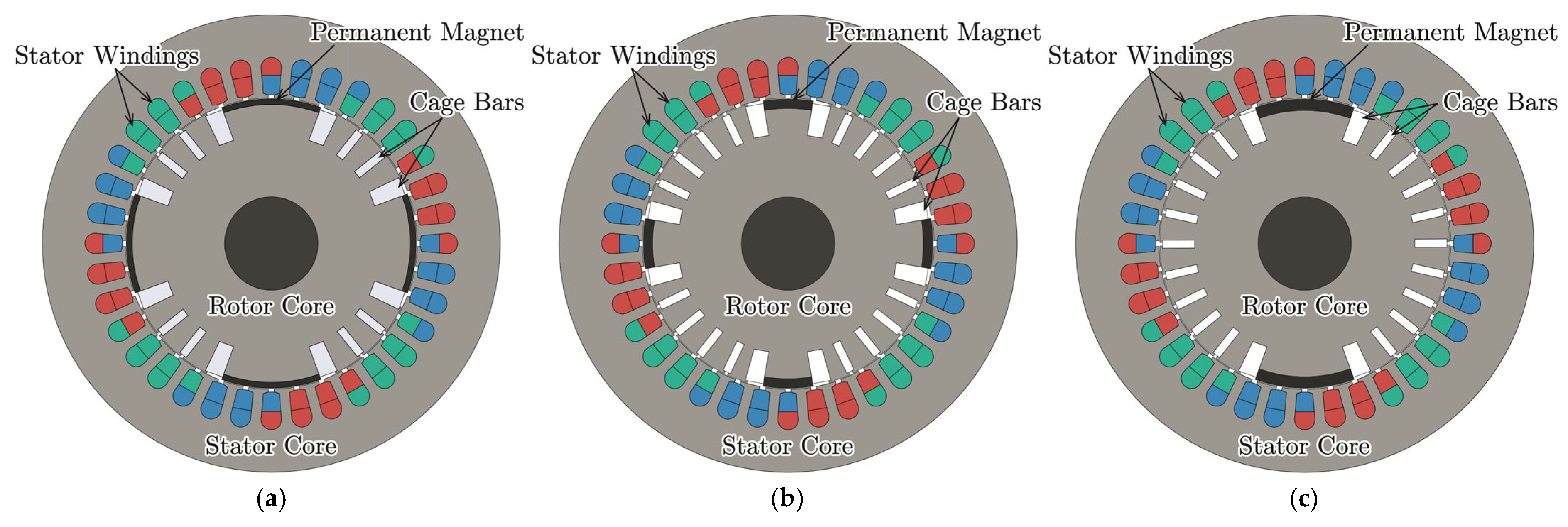
A preliminary study is conducted to compare three SPM configurations for line-start motors. The objective is to clarify the advantages and limitations of SPM structures prior to analyzing the consequent-pole design adopted in this study. An FEM analysis is applied to evaluate electromagnetic characteristics, focusing on torque–slip characteristics during asynchronous operation and performance in synchronous operation. The three configurations are illustrated in
Figure 1. Model A is a conventional 4-pole design with PMs of 40° mechanical angle (mech.) in span and 2 mm in height. Model B is another conventional 4-pole design with PMs of 20° mech. in span and 4 mm in height. Model C is a consequent-pole 4-pole design with two PMs of 40° mech. in span and 4 mm in height mounted on alternate poles. The remaining poles are iron poles. Each iron pole acts as a consequent pole paired with its adjacent magnetized pole. The stator design, including the core geometry and winding arrangement, as well as the total magnet volume and material quality, are identical across the three configurations.
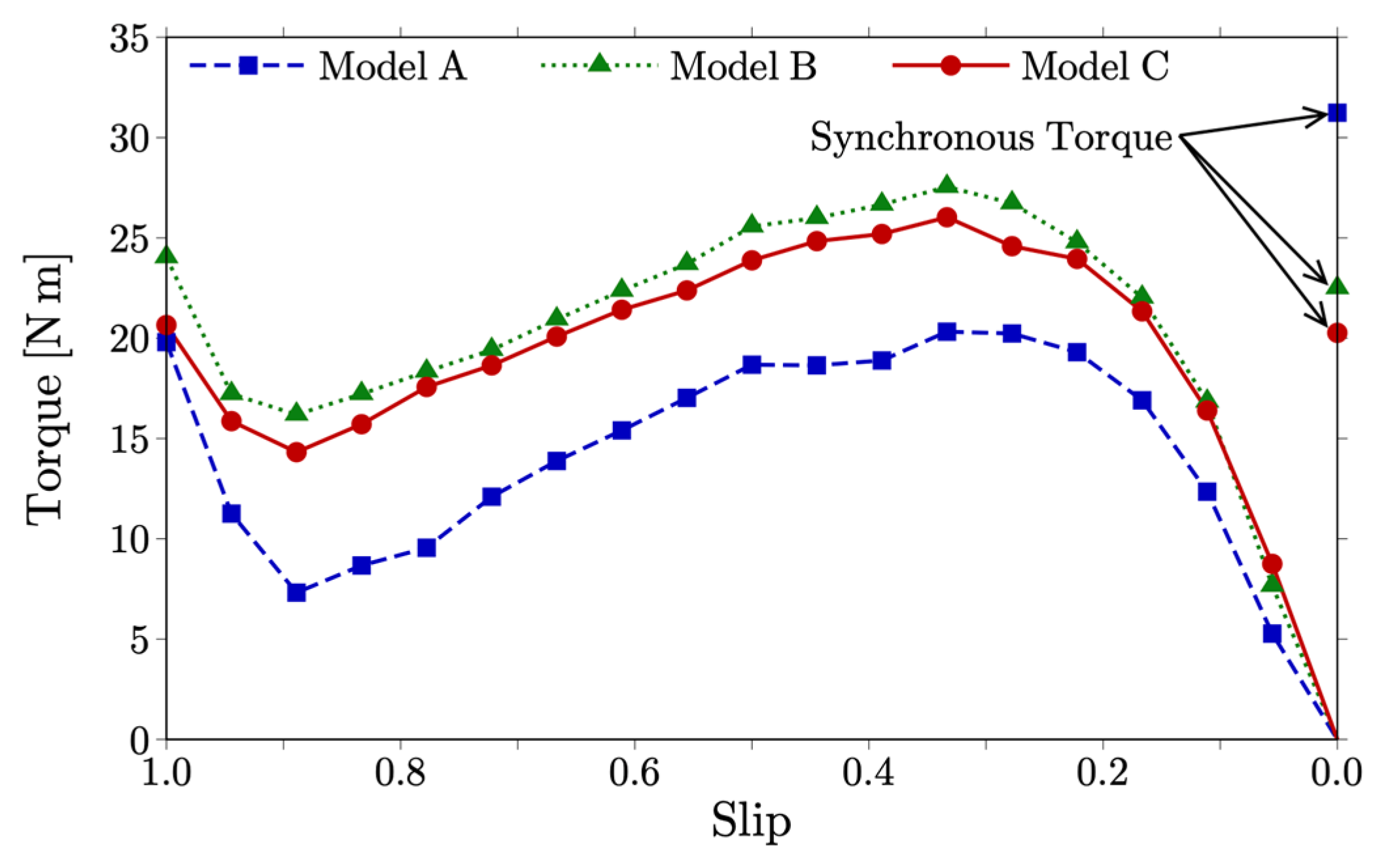
Figure 2 shows the torque–slip characteristics of the three configurations during asynchronous operation. The torque values at the synchronous speed in
Figure 2 correspond to the electromagnetic torque generated by the PMs under no-slip synchronous condition.
Table 1 summarizes their performance characteristics in synchronous operation. Model A exhibits the largest torque and the highest efficiency in synchronous operation because of its large air-gap flux and short flux path. Its asynchronous torque is the smallest due to the limited space for the cage bars, and it is insufficient to start the motor under the rated load torque of 12 N·m. Model B provides the second-largest torque, while it shows the lowest efficiency in synchronous operation because of its small air-gap flux and long flux path. Its asynchronous torque is sufficient for the rated load torque. Model C produces the smallest torque and the second-highest efficiency in synchronous operation. Its asynchronous torque is also sufficient for the rated load torque. Among the three, Model C demonstrates the most balanced performance. Therefore, the consequent-pole SPM configuration is selected for detailed investigation in this paper.
2.2. Configuration of the Consequent-Pole Motor
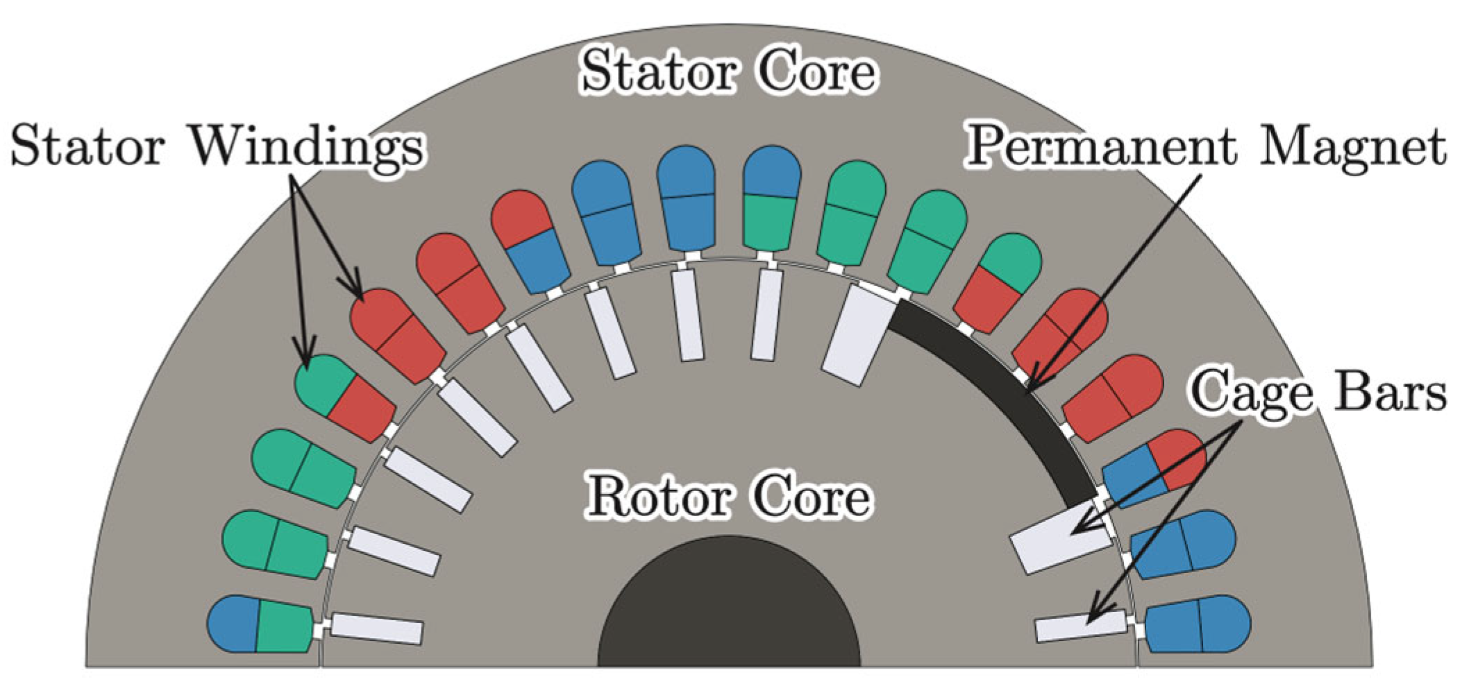
Figure 3 shows the structure of the analyzed line-start SPM motor. The design is based on the configuration previously proposed in our earlier works [
18,
19,
20]. The motor adopts a consequent-pole configuration in which two surface-mounted PMs with identical polarity form an effective 4-pole arrangement. Because the rotor core has no flux barrier, the rotor retains a simple geometry and can be manufactured easily. Magnetized PMs are attached after the casting process to improve manufacturability. The rotor contains 22 aluminum cage bars. The bars adjacent to the PMs are slightly larger than the others. These larger bars act as flux barriers and also provide mechanical support for the magnets. This design enables satisfactory starting characteristics. The specifications and design parameters of the motor are listed in
Table 2. The stator employs double-layer short-pitch windings with a pitch ratio of 8/9. The PM material is neodymium magnet (N42SH), and the core material is non-oriented magnetic steel (50H250).
2.3. Electromagnetic Analysis of the Consequent-Pole Motor
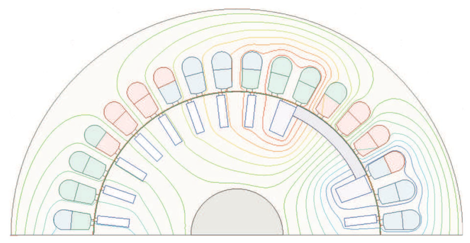
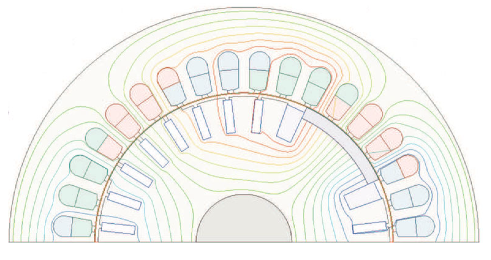
The electromagnetic characteristics of the analyzed motor are evaluated using an FEM analysis. First, the flux distribution due to the PMs is calculated to confirm that the analyzed rotor structure realizes a 4-pole consequent-pole configuration.
Figure 4 shows the flux distribution obtained without current excitation. Closed flux lines extending from the surface of the PMs are observed across the air gap toward the rotor core. The flux concentrates in the regions corresponding to the iron poles. Thus, opposite magnetic polarity is established in these regions. This flux distribution forms effective consequent poles.
Next, the torque–slip characteristics are calculated to evaluate the starting capability.
Figure 5 presents the torque–slip curves of the analyzed motor with those of a conventional induction motor for comparison. The induction motor employs an identical stator design to that of the analyzed motor, while its rotor consists of 28 cage bars. The supply voltage is fixed at 200 V. Although the braking torque caused by the magnets reduces the asynchronous torque in the low-speed region, the analyzed motor exhibits characteristics similar to those of the induction motor. At synchronous speed with zero slip, the analyzed motor operates as a synchronous motor and produces a torque of 22 N·m, which sufficiently exceeds the rated torque of 12 N·m. It should be noted that the torque values in
Figure 5 are obtained under steady-state conditions by the FEM analysis. During the actual starting process, large transient currents flow through both the stator windings and rotor cage because the back electromotive force (EMF) is small at low speed and the large slip induces a strong electromotive force in the rotor cage. As a result, the starting torque becomes higher than the steady-state value. Therefore, the analyzed motor can successfully start even when the load torque is higher than the steady-state torque shown in
Figure 5.
3. Experimental Characteristics
In this section, the line-start consequent-pole SPM motor is fabricated and experimentally evaluated. The purpose of this section is to verify the experimental validity of the analyzed motor and to clarify its practical performance characteristics under line-start operation. Although the experimental data presented here were reported in our previous work [
20], they are included in this paper to confirm the validity of the analyzed motor and to perform a more appropriate and detailed examination of its performance characteristics. The prototype is manufactured according to the design shown in
Figure 3, and its specifications are summarized in
Table 2.
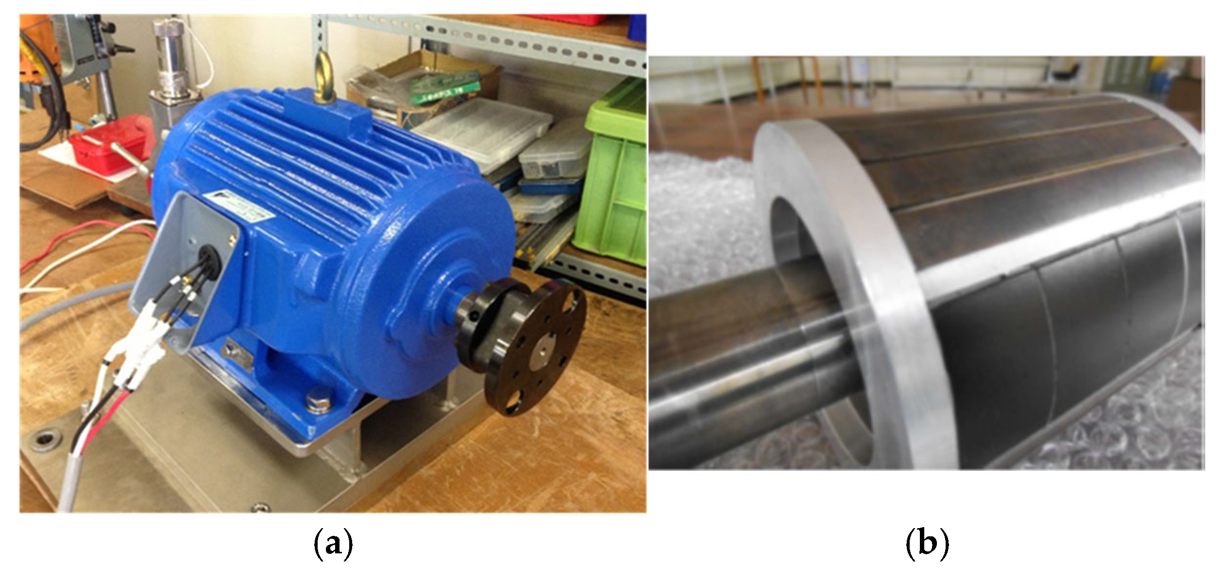
Figure 6 shows photographs of the prototype, including the external view and the rotor. The experimental characteristics of the prototype are evaluated in terms of no-load EMF, starting behavior, and efficiency.
Figure 6a,
Figure 7,
Figure 8 and
Figure 9 are reproduced or redrawn based on our previous work [
20] to ensure consistency in presentation and to provide a clearer explanation of the experimental results discussed in this section.
The experimental measurements were conducted using standard laboratory instruments to ensure accuracy and reproducibility. A powder brake (Mitsubishi Electric ZKB-WN, Tokyo, Japan) was employed to apply the mechanical load torque during the starting and efficiency tests. The torque was measured using a torque detector (ONO Sokki TH-2205, Yokohama, Japan) in combination with a torque converter (ONO Sokki TH-5100, Yokohama, Japan), and the rotational speed was measured by the same system. Electrical quantities such as voltage, current, and power were monitored using a power meter (Yokogawa WT1600, Tokyo, Japan). Waveforms of the measured signals were recorded using a memory HiCorder (Hioki MR8847-01, Nagano, Japan) during the starting tests. Each measurement was repeated three times under identical conditions to confirm repeatability. Measurements for steady-state operation were taken after the motor reached a steady-state thermal condition to ensure stable operation. The recorded data were processed to obtain the average and root-mean-square (RMS) values using standard numerical procedures.
3.1. No-Load EMF
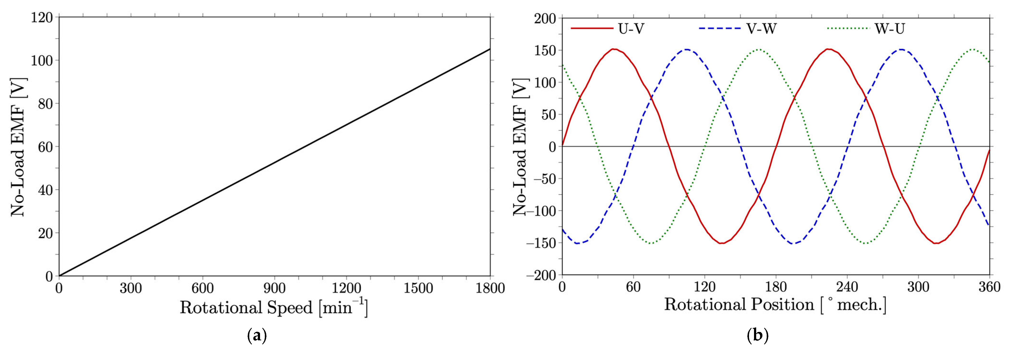
The no-load EMF is proportional to the rotational speed, as shown in
Figure 7a. At the synchronous speed of 1800 min
−1 with a supply frequency of 60 Hz, the RMS value of the EMF reaches 105.1 V. The EMF constant, defined as the EMF per unit speed, is 58 mV/min
−1. In addition, the back-EMF waveform is measured with respect to the rotor mechanical position at the synchronous speed of 1800 min
−1, as shown in
Figure 7b. The waveform exhibits a slightly distorted sinusoidal shape. This distortion reflects the influence of the consequent-pole rotor structure on the air-gap flux distribution. It causes minor torque ripple and a slight reduction in efficiency under sinusoidal excitation. A detailed discussion on the non-sinusoidality of the air-gap flux density and its improvement strategy is presented in
Section 4.
3.2. Starting Characteristics
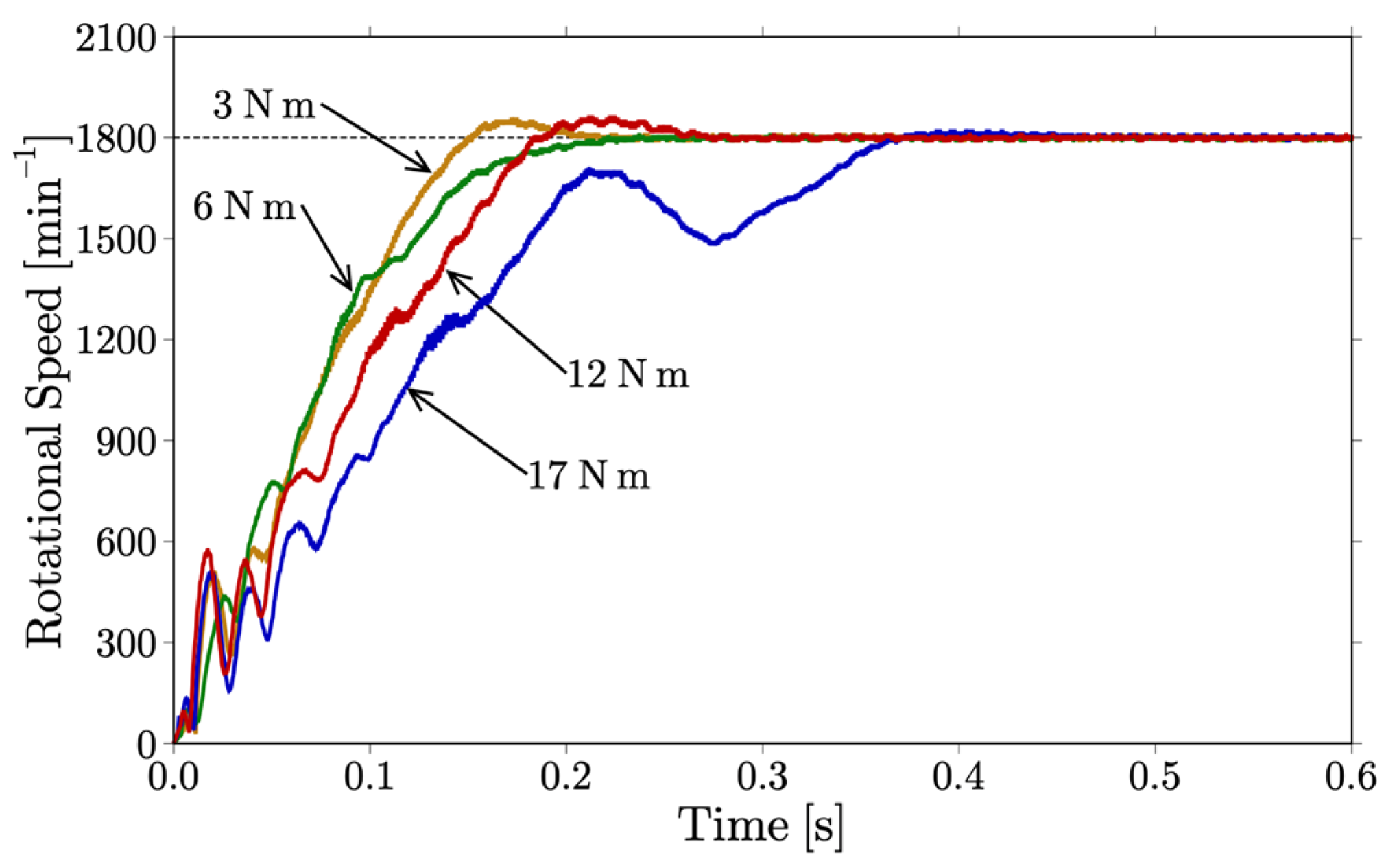
Figure 8 shows the speed profiles of the prototype during the starting process at a supply voltage of 200 V and a frequency of 60 Hz. The experiments were carried out using a powder brake with load torques of 3, 6, 12, and 17 N·m. The rotational speed reaches the synchronous speed in 0.26 s at the rated torque of 12 N·m. At 17 N·m, which corresponds to 142% of the rated torque, it takes approximately 0.4 s. The motor fails to synchronize at load torques above 17 N·m.
3.3. Efficiency
Figure 9 presents the efficiency, phase current, and separated losses of the prototype with respect to output power at the synchronous speed of 1800 min
−1 with a supply voltage of 200 V. In
Figure 9a, the efficiency increases with output power and saturates at approximately 80% beyond 1 kW. The efficiency reaches 77.6% at the rated output of 2.2 kW. In
Figure 9b, the phase current increases with output power.
Figure 9c shows the separated losses measured according to the Japan Standard JEC-TR-21001-2005 [
21]. The copper loss increases with output power and reaches 260 W at the rated output of 2.2 kW. This value is significantly larger than the other losses. The relatively low efficiency and the increase in phase current are caused by the mismatch between the no-load EMF of 105.1 V at synchronous speed and the supply voltage of 200 V. This mismatch induces large lagging currents, which increase copper losses and reduce efficiency.
4. Simple Rotor Design for Performance Improvement
In this section, simple rotor design strategies are investigated to improve torque and efficiency without sacrificing ease of manufacturing. The focus is the mitigation of the non-sinusoidal air-gap flux distribution, which is one of the main causes of efficiency reduction. Similar optimization approaches for consequent-pole motors have recently been reported to improve flux distribution and reduce torque ripple [
22,
23]. However, those studies focused on conventional SPM motors, whereas the present work investigates a line-start consequent-pole SPM motor, where the starting capability and asynchronous behavior must also be considered. The other factor, large lagging current, originates from the mismatch between the no-load EMF and the supply voltage. This mismatch can be resolved by designing the no-load EMF to match the supply voltage, an independent design issue. Therefore, the present study concentrates on improving the flux distribution through rotor design modifications.
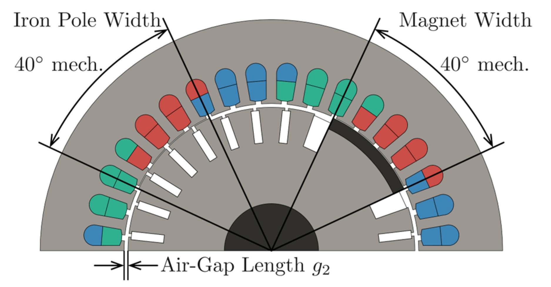
A flux concentration concept is considered to increase the fundamental component of the air-gap flux. In this approach, the air-gap length on both sides of each iron pole is intentionally enlarged to steer the flux path toward a more sinusoidal distribution. This clearance is denoted as g
2.
Figure 10 illustrates a flux concentration design. In this design, the air-gap length g
2 around the iron poles is increased to 1.3 mm and the width of the iron pole is set to 40° mech., which is equal to that of the PM pole.
Figure 11 shows the flux lines of this design obtained through the FEM analysis. This confirms that the flux distribution becomes closer to sinusoidal compared with the original design.
The effect of the design parameter g
2 is examined numerically.
Figure 12a shows that the maximum torque at synchronous speed increases as the air-gap length g
2 is enlarged from 0.3 mm to 1.8 mm.
Figure 12b presents the efficiency characteristics. The efficiency is higher than that of the prototype when the air-gap length g
2 is in the range of 0.3 mm to 1.2 mm, and the maximum value is obtained at g
2 = 0.5 mm.
Figure 12c shows the starting performance at the rated load torque of 12 N·m. Although an excessive increase in g
2 causes a pronounced dip in the speed response at around 30 ms, the starting performance remains sufficiently robust. These results indicate that moderate values of g
2 achieve a balance between synchronous performance and starting characteristics.
These investigations demonstrate that the flux concentration approach provides an effective means of improving both torque and efficiency while preserving the simple rotor structure and ease of manufacturing of the consequent-pole design. Although the air-gap flux distribution becomes more spatially symmetric owing to the flux concentration design, the back-EMF waveform does not necessarily become more sinusoidal. Depending on the design parameter g2, a slight improvement in waveform symmetry may be observed, whereas in some cases the distortion can even increase because the inherent magnetic asymmetry between magnetized and iron poles remains.
5. Conclusions
In this paper, the fundamental characteristics of a line-start consequent-pole SPM motor are experimentally demonstrated. The prototype synchronizes smoothly under load and reaches synchronous speed at the rated torque. The efficiency is limited by two factors. One is the mismatch between the no-load EMF and the supply voltage, which can be resolved by conventional design adjustments. The other is the non-sinusoidal air-gap flux distribution inherent to the consequent-pole structure, which requires further investigation. Focusing on the latter, rotor design strategies are examined by enlarging the air-gap length adjacent to the iron poles to enhance the fundamental flux component. The analysis shows that this approach improves torque and efficiency while maintaining satisfactory starting performance, and the optimized design achieves a measurable efficiency improvement compared with the prototype.
In contrast to our previous works [
18,
19,
20], this study provides a deeper experimental discussion and introduces simplified rotor design guidelines that can be readily applied to practical line-start consequent-pole SPM motors. These results clarify the design–performance relationship and contribute to the development of high-efficiency, easy-to-manufacture industrial drives.
Author Contributions
Conceptualization, Y.Y. and T.H.; methodology, Y.Y., Y.M. and T.H.; software, T.H. (ANSYS Maxwell, Ansys Inc., Canonsburg, PA, USA; available online:
https://www.ansys.com/products/electronics/ansys-maxwell, accessed on 20 September 2025); validation, Y.Y. and T.H.; formal analysis, T.H.; investigation, Y.Y., Y.M. and T.H.; resources, Y.M. and T.H.; data curation, T.H.; writing—original draft preparation, T.H.; writing—review and editing, Y.Y. and T.H.; visualization, Y.Y. and T.H.; supervision, T.H.; project administration, Y.Y. and T.H.; funding acquisition, Y.M. and T.H. All authors have read and agreed to the published version of the manuscript.
Funding
This research received no external funding.
Data Availability Statement
Data are contained within the article.
Acknowledgments
The authors would like to thank Tomoaki Egawa, Hiroaki Saikusa, and Soei Akita for their assistance with the design analysis and experiments. The authors also gratefully acknowledge Yaskawa Electric Corporation for manufacturing the prototype.
Conflicts of Interest
Author Yasuhiro Miyamoto is the representative of the company J. A. M. Engineering Institute Co. Ltd. The remaining authors declare that the research was conducted in the absence of any commercial or financial relationships that could be construed as a potential conflict of interest.
Abbreviations
The following abbreviations are used in this manuscript:
| EMF | Electromotive Force |
| FEM | Finite Element Method |
| IPM | Interior Permanent Magnet |
| LSPM | Line-Start Permanent Magnet |
| PM | Permanent Magnet |
| RMS | Root Mean Square |
| SPM | Surface Permanent Magnet |
References
- Hamdi, E.S. Design of Small Electrical Machines; John Wiley & Sons: Chichester, UK, 1994. [Google Scholar]
- Hendershot, J.R.; Miller, T.J.E. Design of Brushless Permanent-Magnet Machines, 2nd ed.; Motor Design Books LLC: Venice, FL, USA, 2010. [Google Scholar]
- Palangar, M.F.; Soong, W.L.; Bianchi, N.; Wang, R.-J. Design and Optimization Techniques in Performance Improvement of Line-Start Permanent Magnet Synchronous Motors: A Review. IEEE Trans. Magn. 2021, 57, 900214. [Google Scholar] [CrossRef]
- Ould Lahoucine, Y.; Raute, R.; Caruana, C. Line-Start Permanent Magnet Synchronous Motors: Evolution, Challenges, and Industrial Prospects. Energies 2025, 18, 4545. [Google Scholar] [CrossRef]
- Kurihara, K.; Rahman, M.A. High-Efficiency Line-Start Interior Permanent-Magnet Synchronous Motors. IEEE Trans. Ind. Appl. 2004, 40, 789–796. [Google Scholar] [CrossRef]
- Damaki Aliabad, A.; Mirsalim, M.; Farrokhzad Ershad, N. Line-Start Permanent-Magnet Motors: Significant Improvements in Starting Torque, Synchronization, and Steady-State Performance. IEEE Trans. Magn. 2010, 46, 4066–4072. [Google Scholar] [CrossRef]
- Mingardi, D.; Bianchi, N.; Dai Prè, M. Geometry of Line Start Synchronous Motors Suitable for Various Pole Combinations. IEEE Trans. Ind. Appl. 2017, 53, 4360–4367. [Google Scholar] [CrossRef]
- Wu, F.; Wang, X.; Bao, X.; Li, R. Design and Analysis of a Less-Magnets Consequent-Pole Line-Start Permanent Magnet Motor with Low Cogging Torque. IET Electr. Power Appl. 2024, 18, 941–951. [Google Scholar] [CrossRef]
- Rabbi, S.F.; Rahman, M.A. Critical Criteria for Successful Synchronization of Line-Start IPM Motors. IEEE J. Emerg. Sel. Top. Power Electron. 2014, 2, 348–358. [Google Scholar] [CrossRef]
- Tsuboi, K.; Hirotsuka, I.; Takegami, T.; Nakamura, M. Basic Concept of an Analytical Calculation Method and Some Test Results for Determination of Constant of Line Start Permanent Magnet Motor. In Proceedings of the 11th International Conference on Electrical Machines and Systems, Wuhan, China, 17–20 October 2008; pp. 3108–3111. [Google Scholar]
- Farooq, H.; Bracikowski, N.; La Delfa, P.; Hecquet, M. Modelling of Starting and Steady-State Performance of Line Start Permanent Magnet Synchronous Motor using Reluctance Network. In Proceedings of the International Conference on Electrical Machines, Valencia, Spain, 5–8 September 2022; pp. 226–231. [Google Scholar]
- Szeląg, W.; Jedryczka, C.; Baranski, M. A New Method of Reducing the Inrush Current and Improving the Starting Performance of a Line-Start Permanent-Magnet Synchronous Motor. Energies 2024, 17, 1040. [Google Scholar] [CrossRef]
- Lee, C.K.; Kwon, B.I.; Kim, B.-T.; Woo, K.I.; Ham, M.G. Analysis of magnetization of magnet in the rotor of line start permanent magnet motor. IEEE Trans. Magn. 2003, 39, 1499–1502. [Google Scholar] [CrossRef]
- Lee, C.K.; Kwon, B.I. Design of post-assembly magnetization system of line start permanent-magnet motors using FEM. IEEE Trans. Magn. 2005, 41, 1928–1931. [Google Scholar] [CrossRef]
- Melfi, M.J.; Umans, S.D.; Atem, J.E. Viability of Highly Efficient Multi-Horsepower Line-Start Permanent-Magnet Motors. IEEE Trans. Ind. Appl. 2015, 51, 120–128. [Google Scholar] [CrossRef]
- Zöhra, B.; Akar, M.; Eker, M. Design of a Novel Line Start Synchronous Motor Rotor. Electronics 2019, 8, 25. [Google Scholar] [CrossRef]
- Huang, P.W.; Mao, S.H.; Tsai, M.C.; Liu, C.T. Investigation of Line Start Permanent Magnet Synchronous Motors with Interior-Magnet Rotors and Surface-Magnet Rotors. In Proceedings of the 11th International Conference on Electrical Machines and Systems, Wuhan, China, 17–20 October 2008; pp. 2888–2893. [Google Scholar]
- Higuchi, T.; Yokoi, Y.; Abe, T.; Egawa, T. Fundamental Characteristics of a Novel Self-Starting Type Permanent Magnet Synchronous Motor. In Proceedings of the 15th International Conference on Electrical Machines and Systems, Sapporo, Japan, 21–24 October 2012. LS4A-3. [Google Scholar]
- Arikawa, S.; Higuchi, T.; Yokoi, Y.; Abe, T.; Miyamoto, Y.; Ohto, M. Motion Characteristics of a Novel Self-Start Type Permanent Magnet Synchronous Motor. In Proceedings of the 16th International Conference on Electrical Machines and Systems, Busan, Korea, 26–29 October 2013; pp. 109–112. [Google Scholar]
- Akita, S.; Higuchi, T.; Yokoi, Y.; Saikusa, H.; Abe, T.; Makino, S. Experimental Characteristics of a Line-Start Permanent Magnet Motor. In Proceedings of the 19th International Conference on Electrical Machines and Systems, Chiba, Japan, 13–16 November 2016. DS2G-1-17. [Google Scholar]
- JEC-TR-21001-2005; Test Procedures for Permanent Magnet Synchronous Machines. The Institute of Electrical Engineers of Japan: Tokyo, Japan, 2005; pp. 10–14.
- Chung, S.-U.; Moon, S.-H.; Kim, D.-J.; Kim, J.-M. Development of a 20-Pole–24-Slot SPMSM with Consequent Pole Rotor for In-Wheel Direct Drive. IEEE Trans. Ind. Electron. 2016, 63, 302–309. [Google Scholar] [CrossRef]
- Jo, S.-J.; Baek, S.-W.; Hwang, K.-Y. Optimization Design of Novel Consequent Pole Motor for Electric Power Steering System. Machines 2024, 12, 893. [Google Scholar] [CrossRef]
| Disclaimer/Publisher’s Note: The statements, opinions and data contained in all publications are solely those of the individual author(s) and contributor(s) and not of MDPI and/or the editor(s). MDPI and/or the editor(s) disclaim responsibility for any injury to people or property resulting from any ideas, methods, instructions or products referred to in the content. |
© 2025 by the authors. Licensee MDPI, Basel, Switzerland. This article is an open access article distributed under the terms and conditions of the Creative Commons Attribution (CC BY) license (https://creativecommons.org/licenses/by/4.0/).
