1. Introduction
Permanent magnet synchronous motors (PMSMs) offer advantages such as high power density, rapid speed response, and a wide speed regulation range. They are widely used in electric-drive applications, including in smart manufacturing, electric vehicles, robotics, and unmanned aerial vehicles [
1,
2]. Joint-drive motors, used in the manufacture of equipment, utilize various control strategies, such as proportional–integral (PI) linear control, hysteresis current control, and predictive control, to achieve a superior dynamic response and greater control accuracy [
3]. While PI control effectively reduces steady-state error, its fixed switching frequency can result in suboptimal dynamic performance in certain conditions [
4]. Hysteresis current control is simple and offers a rapid response; however, current fluctuations during operation may cause peak currents to exceed their limit values [
5]. However, predictive control demonstrates favorable dynamic performance in terms of aspects such as dynamic response and current tracking. Coupled with its straightforward structure and ease of implementation, this makes it a popular choice for permanent magnet synchronous motor control systems [
6,
7]. Predictive control can be categorized into two main types: Model Predictive Control (MPC) and Discrete-Phase Current Predictive Control (DPCC). MPC algorithms predict the instantaneous current by describing the voltage vector cost function. However, the finite number of voltage vectors inevitably generates current ripple during the prediction process [
8]. In contrast, DPCC algorithms that use discrete motor models can obtain a greater number of voltage vectors. This enables the predicted current to track the reference current more accurately [
9,
10]. However, DPCC is a motor-model-based control method with inherent limitations, as its predictive efficacy depends on the accuracy of the motor model. During motor control, issues arising from parameter mismatch due to parameter variations and model uncertainties can induce significant current harmonics, increased current tracking errors and amplified torque ripple, thereby compromising the stability of the control system [
11]. Several improvement methods have been developed to overcome the degradation in control system performance caused by parameter mismatch, such as disturbance estimation [
12], compensating controllers [
13], and parameter identification [
14].
Parameter identification techniques can be divided into two categories: offline parameter identification [
15] and online parameter identification [
16]. Commonly used online identification methods include extended Kalman filtering [
17], recursive least squares [
18], and model reference adaptive filtering [
19]. Reference [
20] proposes a sensorless control parameter identification method that uses current and voltage information to estimate the resistance and back EMF constants under various load conditions. Reference [
21] fully considers the impact of stator resistance and magnetic flux uncertainty on the control system and uses MRAS for parameter estimation, but MRAS requires advanced information sampling to enable the identification system to quickly enter the convergence stage. Reference [
22] employs a novel adaptive interconnected observer to observe rotor speed, position, and torque and uses a motor model to estimate resistance and inductance. Reference [
23] proposes a speed control algorithm that uses system output equations for parameter identification. The robustness of the algorithm is verified when combined with sliding mode control. Reference [
24] used a method combining MRAS and Popov superstability theory to derive the discrete-time model for each parameter and fully considered the impact of voltage-type inverters on the identification results. Reference [
25] used an identification method based on motor models to estimate resistance and inductance, compared the results with those obtained using EKF identification, and analyzed the advantages and disadvantages of various algorithms. These control strategies mentioned above, based on parameter identification, are very limited in practical applications due to the high complexity of the algorithm. In order to meet more reliable industrial level application algorithms, we designed a low-complexity parameter identification control system.
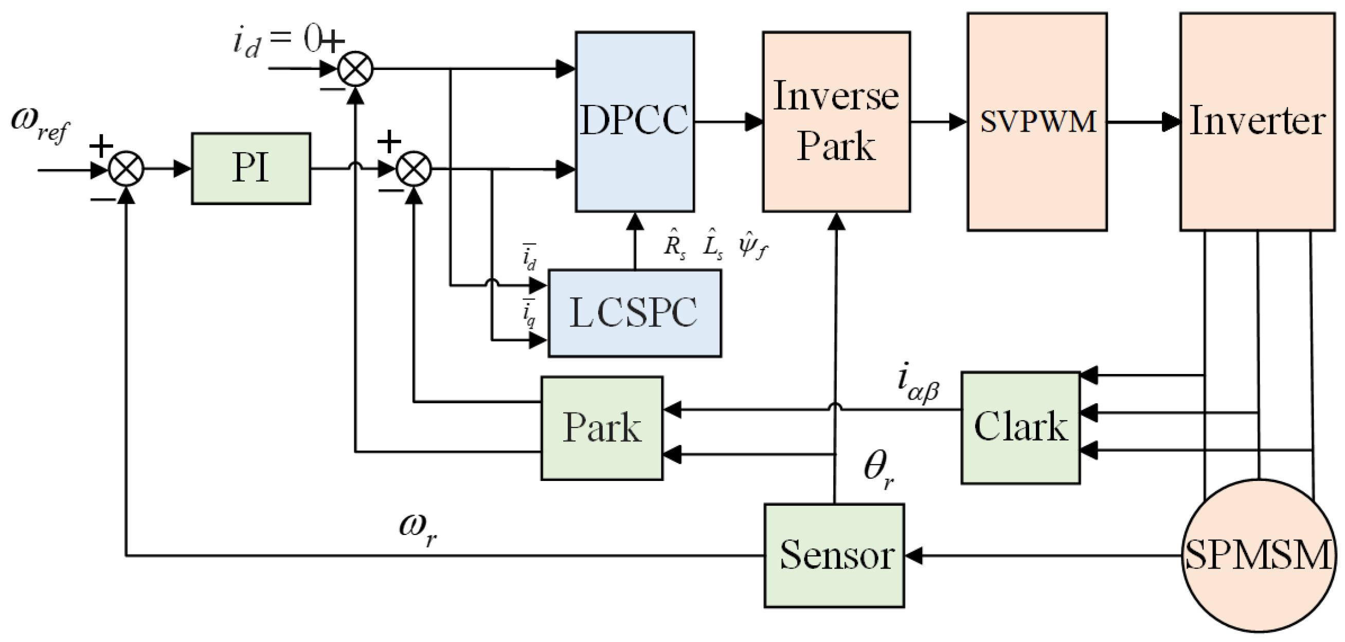
This paper proposes an enhanced current prediction control strategy without dead time, employing the low-complexity specified performance tracking controller (LCSPC) algorithm, the Dead-Time Control with Current Prediction (DPCC) algorithm, and a parameter decoupling model to achieve closed-loop control. This approach addresses transient model changes in the motor model, enables online identification of electrical parameters, and incorporates state feedback from the control system. The principal contributions of this work are as follows:
(1) Low-complexity state feedback controller. We propose a low-complexity state feedback controller decoupling algorithm based on the predictive error model. This approach acquires parameters without employing nonlinear or adaptive methods within the control system and does not require the derivative of the expected trajectory. As it involves no hardware computation, it reduces controller costs.
(2) DPCC parameter decoupling. A parameter prediction model and an incremental current error model were derived using a discrete mathematical model of the motor. This approach fully accounts for under-ranking issues during parameter decoupling and provides a compensation reference quantity for the decoupling model.
(3) Online parameter identification control scheme. A DPCC multi-parameter discrete system identification scheme based on LCSPC has been proposed to enhance performance. Using d/q-axis current error as the algorithmic input reduces the dependency of DPCC on motor models while improving the efficiency of state feedback. Consequently, it mitigates the significant d/q-axis current fluctuations caused by parameter mismatch during motor operation.
2. Mathematical Models of Surface-Mounted Permanent Magnet Synchronous Motors
For motor control systems using FOC control strategies, PI algorithms are generally used to control the current loop. For surface-mounted PMSMs, the d-axis reference current is typically set to zero, and the q-axis reference current is determined by the control output of the speed loop. This paper designs an improved parameter identification method for current control without beat frequency based on the motor mathematical model. The voltage equation of the motor in the d-q reference frame can be expressed as (
1):
where
,
,
, and
are the stator voltage and current in the d-q coordinate system, respectively;
is the stator resistance;
and
are the stator inductances in the
-
coordinate system;
is the rotor angular velocity; and
is the rotor magnetic flux.
The electromagnetic torque equation of the motor can be expressed as (
2):
where
is the electromagnetic torque of the motor, and
is the number of pole pairs of the motor. The motion equation of the motor can be expressed as (
3):
where
is the mechanical angular velocity of the motor,
is the rotational inertia,
is the damping coefficient, and
is the load torque.
5. Simulation Analysis and Experimental Verification
To validate the identification accuracy of the LCSPC-DPCC, this paper establishes two different electrical parameter identification models for surface-mounted permanent magnet synchronous motors in Simulink: a novel deadbeat predictive current prediction control model based on the model reference adaptive identification algorithm and a deadbeat predictive current prediction control model based on low-complexity specified performance tracking. The motor parameters were identified in terms of identification accuracy, convergence speed, and load transients, further validating the advantages of LCSPC-DPCC over MRAS-DPCC.
5.1. Simulation Analysis
The parameters of the permanent magnet synchronous motor are shown in
Table 1. During the simulation process, in order to more intuitively demonstrate the differences between the two identification algorithms, the rotor position information of both simulation models was fed back using an encoder. The simulation time of the system was fixed at 3 s, and the fixed step size was set to 1
s.
To ensure the reliable operation of the parameter feedback module and the control accuracy of the motor control system, constant-speed no-load (1000 r/min, 2000 r/min, 3000 r/min) and variable-speed no-load simulations of the algorithm were first conducted. The variable-speed control simulation refers to an initial speed of 1000 r/min, reaching 2000 rpm at 1 s, and reaching the rated speed of 3000 rpm at 2 s.
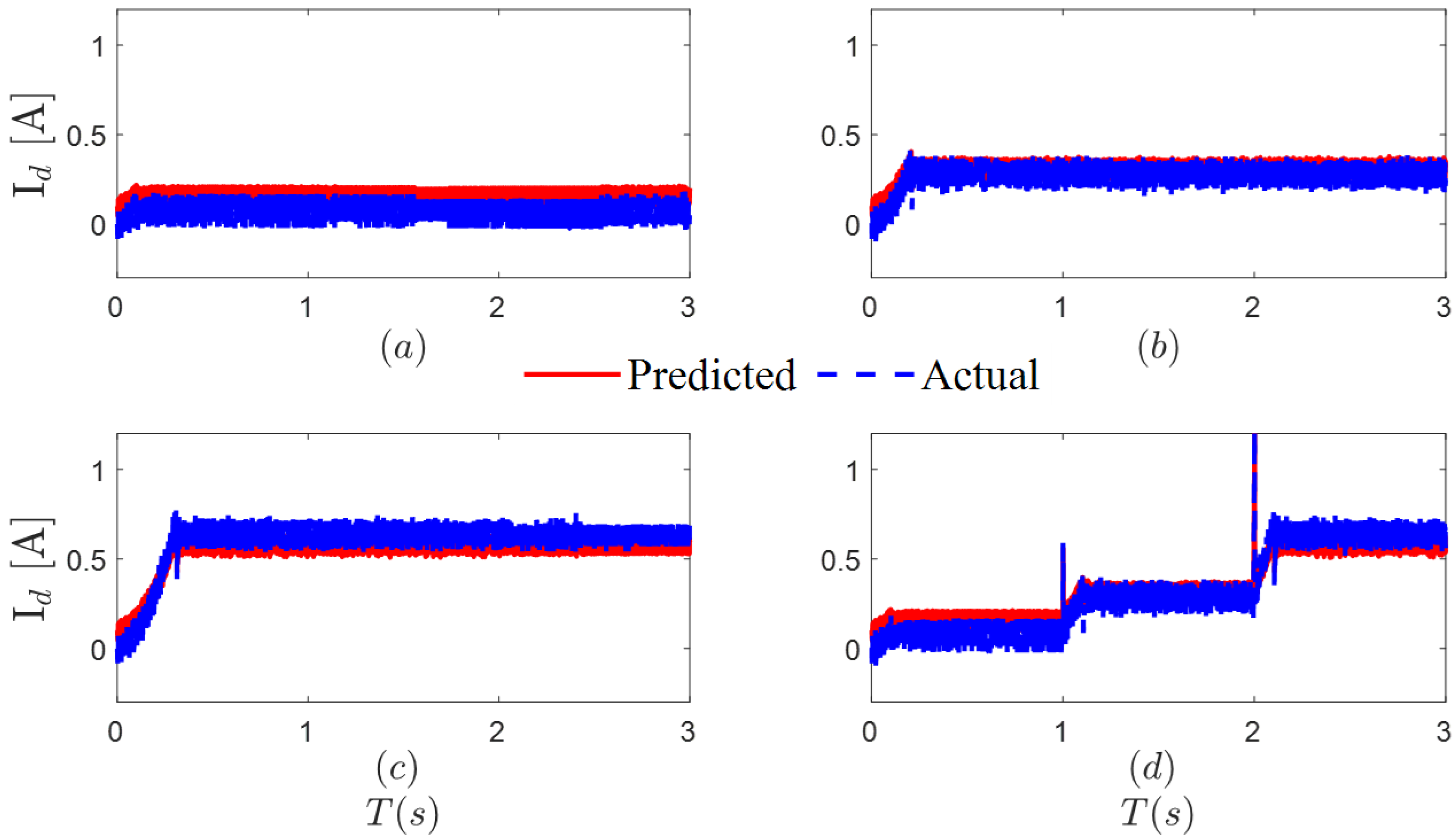
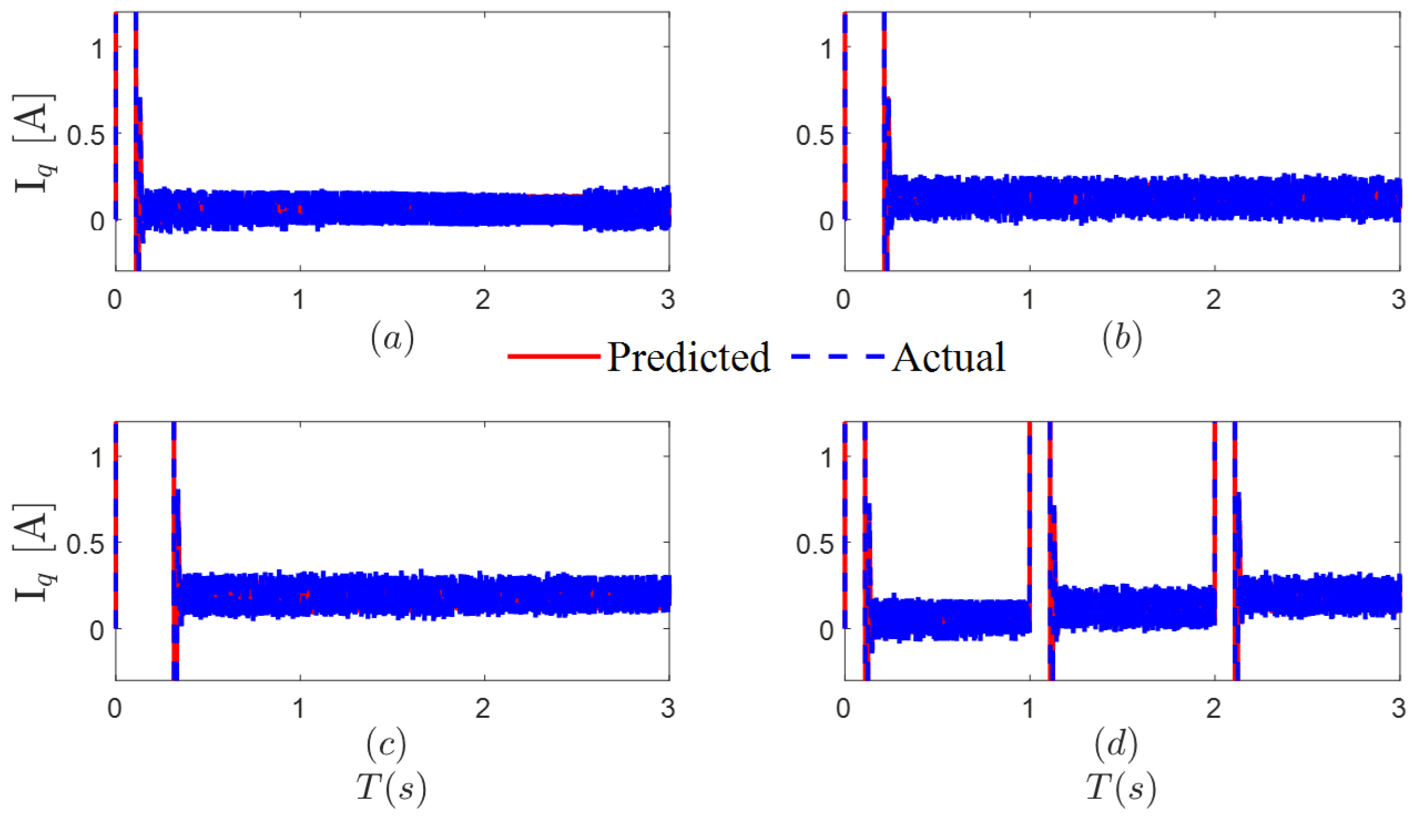
Figure 3 and
Figure 4 show the deviation between the actual current and the reference current when the motor is running at a constant speed and at a variable speed under no-load conditions.
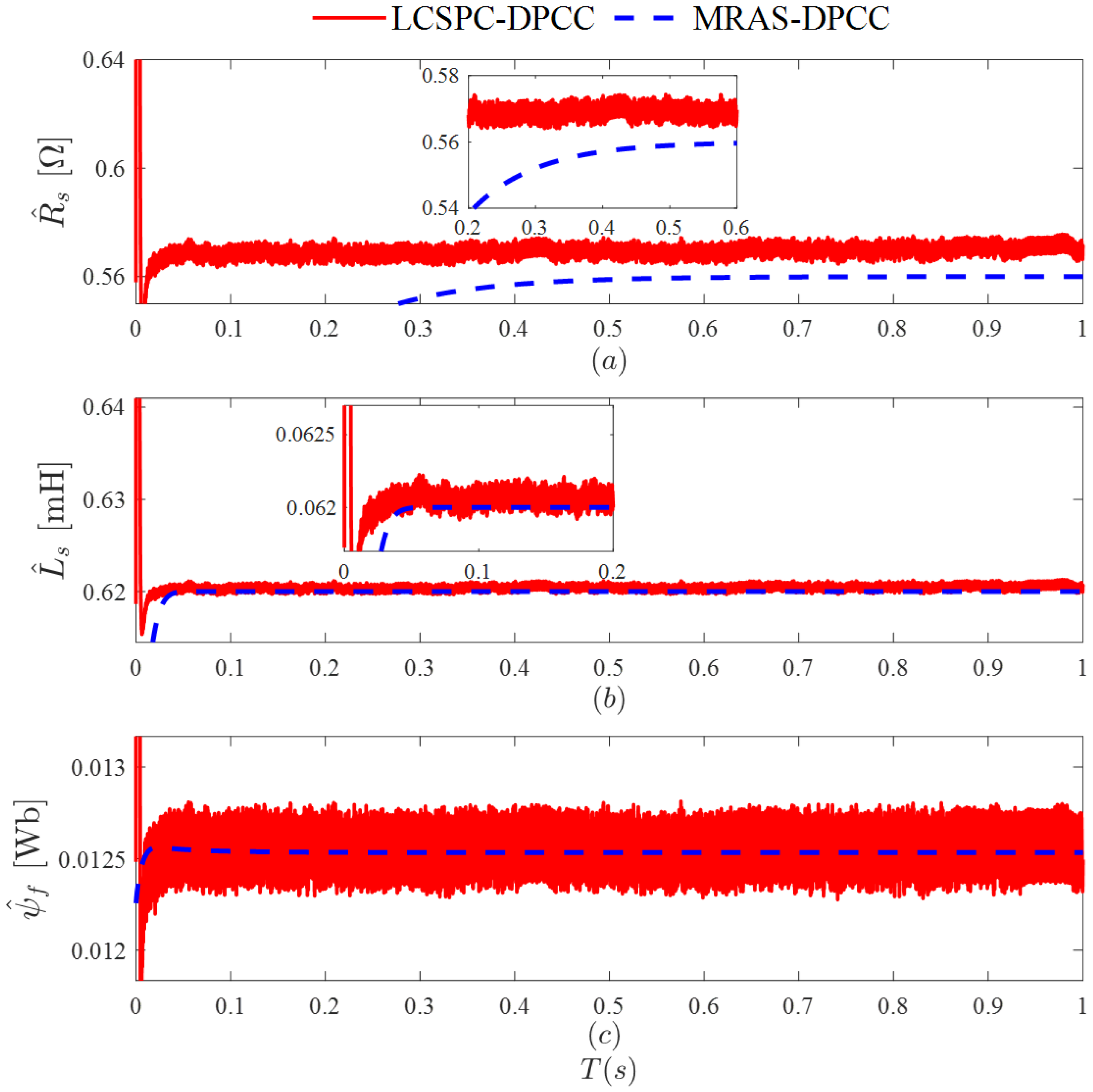
Figure 5 shows the electrical parameter identification results obtained using LCSPC-DPCC and MRAS-DPCC when the motor is running under no-load conditions.
As shown in
Figure 5, both algorithms can effectively track the actual current. However, since MRAS-DPCC uses the real-time feedback of the
d-
q axis actual current from the motor and the motor mathematical model for parameter identification, this inevitably leads to the impact of parameter mismatch on the output torque. Additionally, due to varying degrees of current deviation, the results of parameter identification will also have a certain degree of error. In contrast, the LCSPC-DPCC uses the motor mathematical model after decoupling compensation for parameter identification, effectively reducing the impact of current disturbances on the accuracy of parameter identification.
To study the dynamic performance of the control system under the two algorithms, a load test was conducted. A sudden load of 0.2 Nm was applied at 0.5 s, followed by another sudden increase of 0.2 Nm at 1.5 s, and then all loads were cleared at 2.5 s. Algorithm simulations were performed for the above scenario to obtain the predicted and actual currents in the d-q axes, with the results shown in
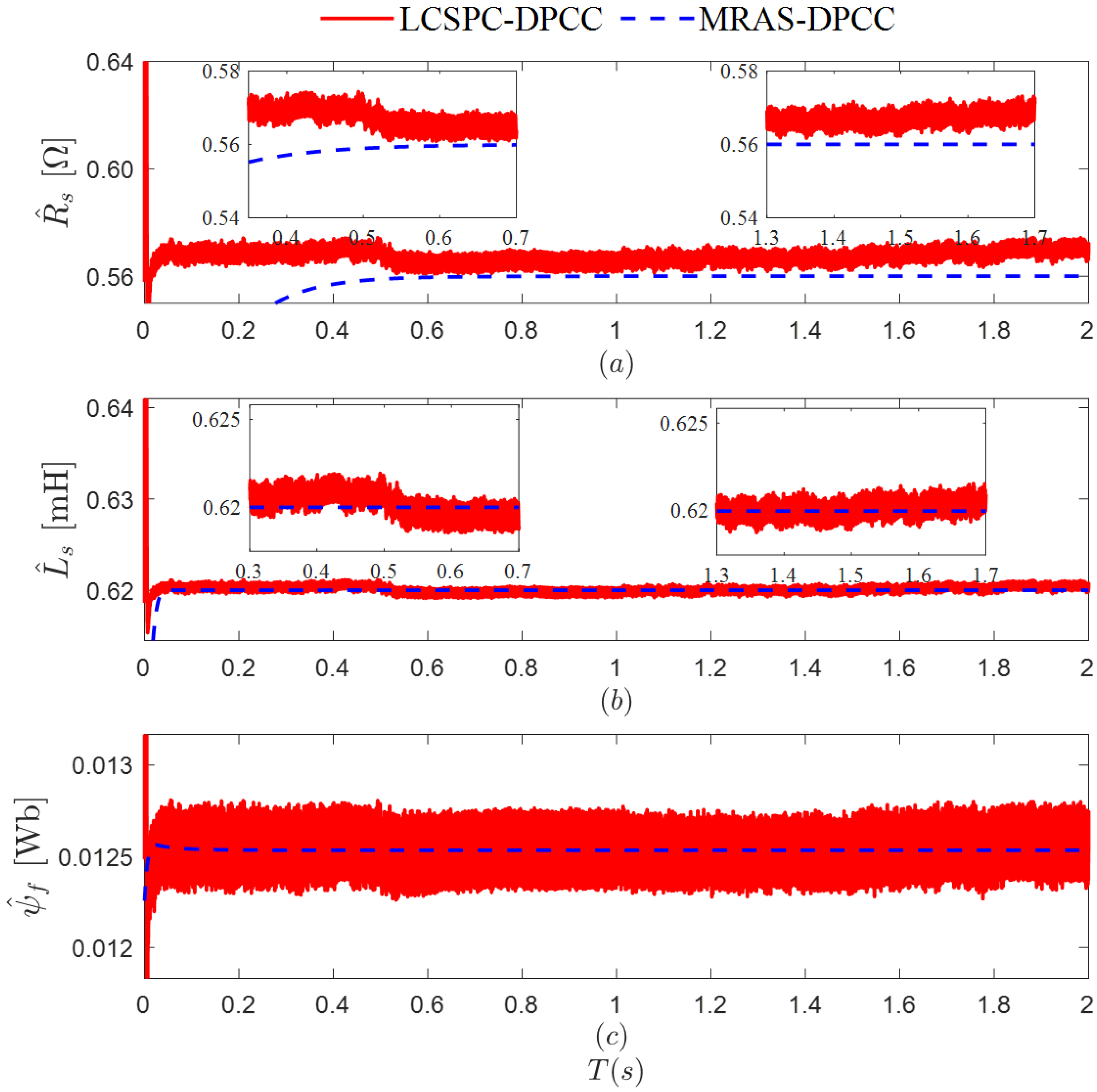
Figure 6. Additionally, the LCSPC-DPCC and MRAS-DPCC algorithms were used to compare the identification of motor electrical parameters, with the results shown in
Figure 7.
Figure 6 shows the temporary mismatch of Ls caused by load changes, which in turn leads to fluctuations in the d/q-axis currents. When the load changes, the d-q-axis currents oscillate within a certain range as the estimated value of Ls changes. Once Ls identification is complete, the d-q-axis currents gradually stabilize. Since
d-
q axis currents exhibit oscillation issues, using MRAS for parameter identification also introduces oscillations into the identification results. This causes the MRAS algorithm’s identification results to oscillate around the actual values, leading to continuous fluctuations in the electrical parameter feedback results and ultimately reducing the motor’s control accuracy. The LCSPC-DPCC algorithm designed in this paper decouples and compensates for resistance, inductance, and magnetic flux from the perspective of the motor’s mathematical model. Therefore, the identification results obtained using this algorithm have higher accuracy and can overcome the influence of external disturbances on the algorithm, consistently meeting the high-precision parameter feedback requirements of the motor control system.
As shown by the simulation results, the accuracy of the resistance, inductance, and magnetic flux identified using MRAS-DPCC is 0.5%, 1.9%, and 1.84%, respectively, while the identification accuracies of the various parameters using LCSPC-DPCC are 0.26%, 0.07%, and 0.24%, respectively, representing improvements of 48.1%, 96.2%, and 86.7% compared to MRAS-DPCC.
5.2. Experimental Verification
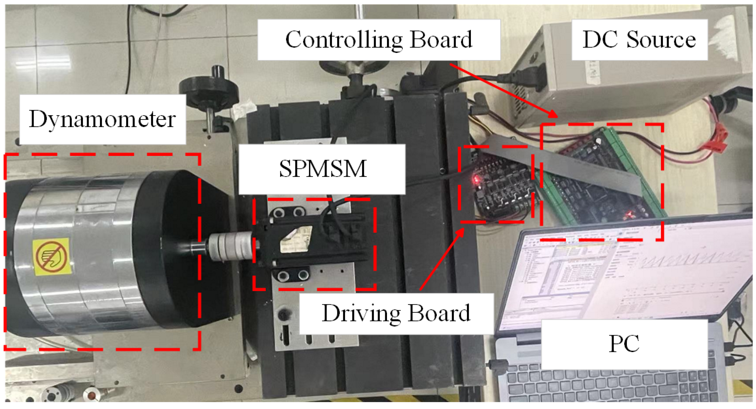
To further test the performance of LCSPC-DPCC, a permanent magnet synchronous motor control system experimental platform was constructed as shown in
Figure 8. Due to the low-complexity advantage of the algorithm, the STM32F407 microcontroller was used to implement the control algorithm.
(1) No-load test:
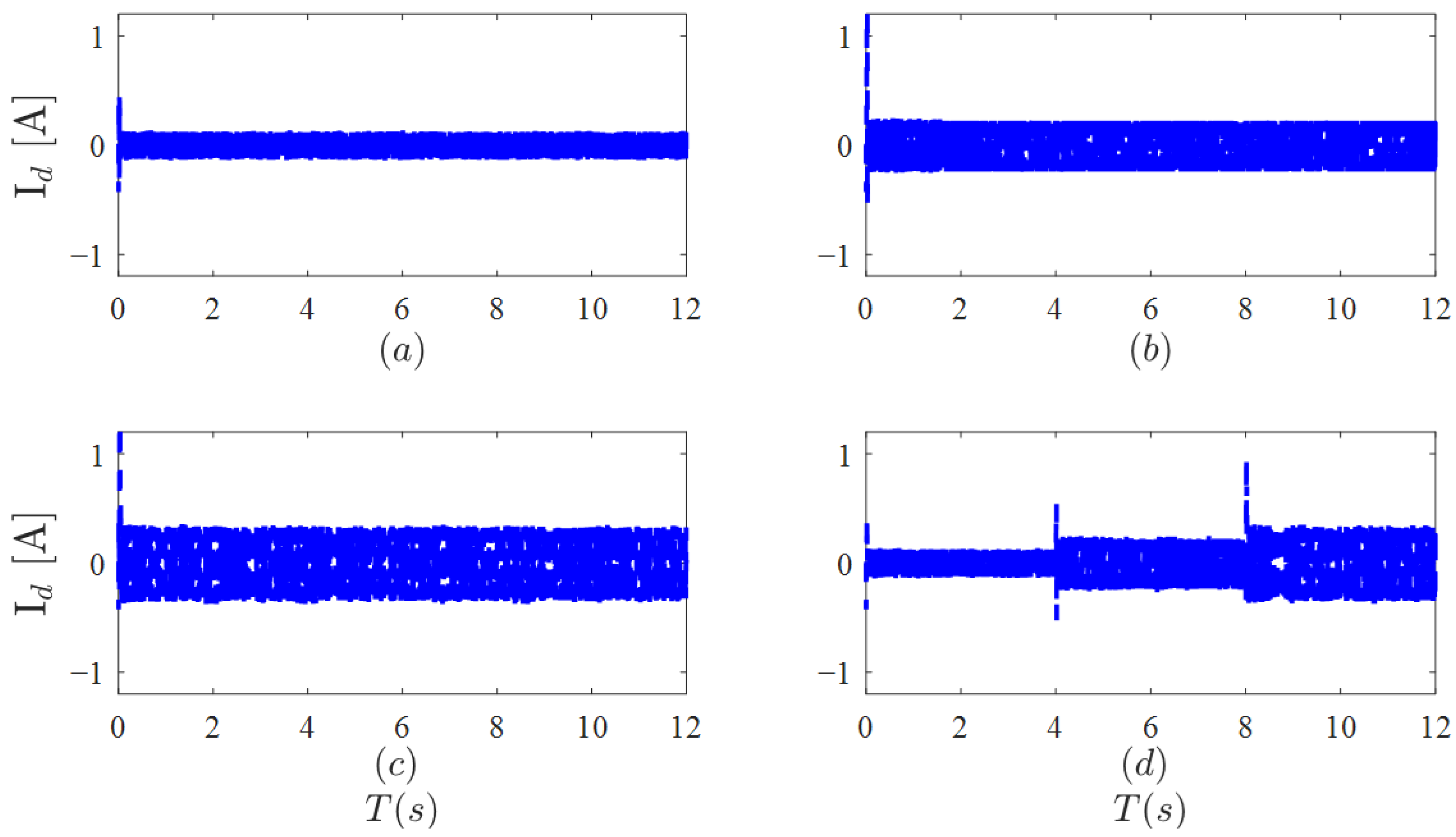
Figure 9 shows the d/q-axis current waveforms corresponding to different speeds under no-load conditions. The expected speeds during the test were set to 1000 r/min, 2000 r/min, 3000 r/min, and variable speed.
To verify the feasibility of zero-beat current predictive control during motor operation, an incremental encoder was used for rotor information feedback. As shown in
Figure 9 and
Figure 10, the non-steady-state errors caused by the motor’s own mechanical characteristics result in the
d-
q axis currents fluctuating around the desired values under different operating speeds. When the speed is switched to 2000 r/min at 4 s, the
d-
q axis currents exhibit a significant fluctuation lasting approximately 0.2 s. When the speed is switched to 3000 r/min at 8 s, the fluctuations in the
d-
q axis currents become even more pronounced.
As shown in
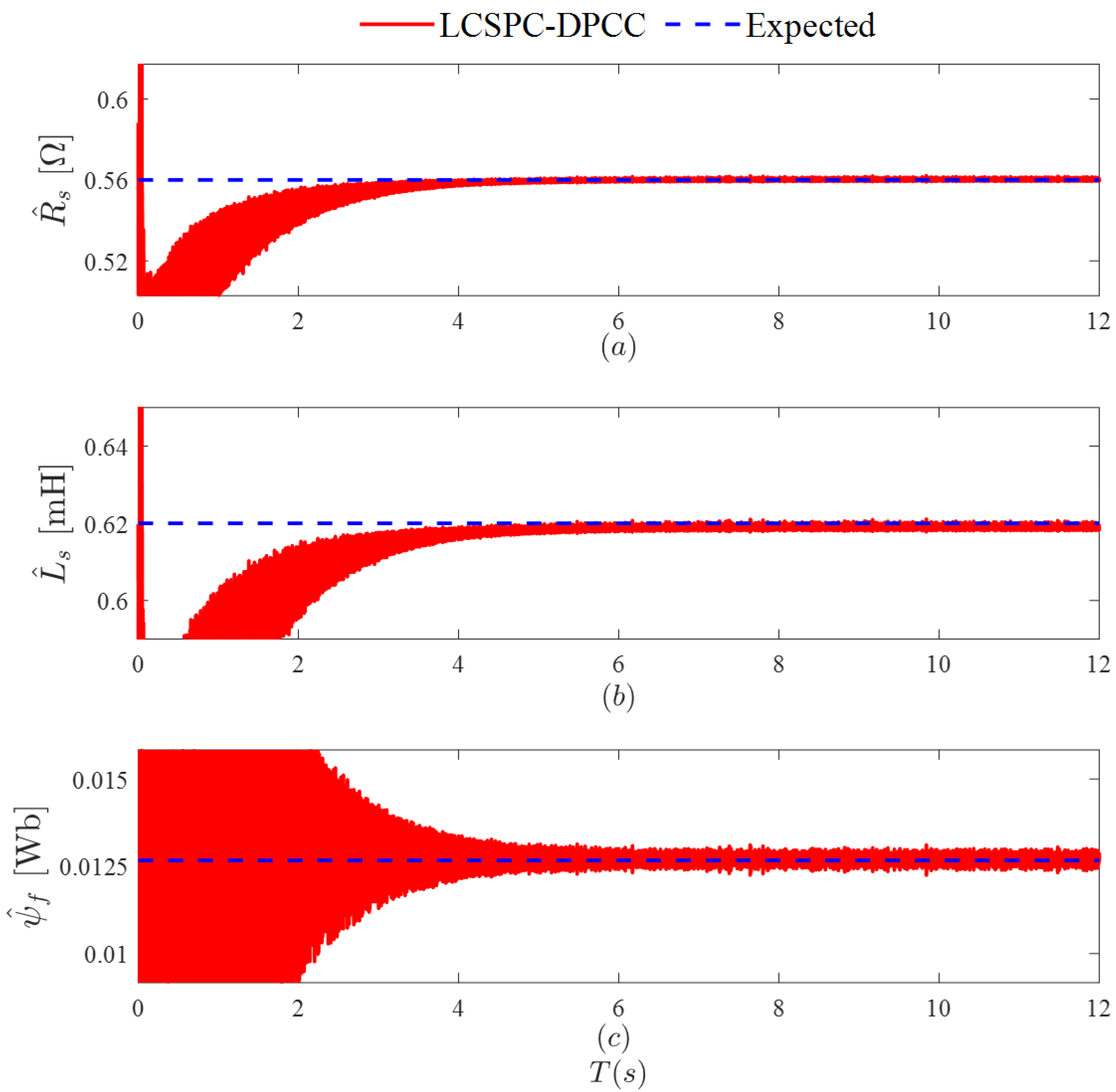
Figure 11, during the speed-up phase, the motor current is in a fluctuating state and cannot provide stable and reliable algorithm inputs. Therefore, the identification results of various parameters during the speed-up phase exhibit significant deviations from actual values. The convergence times for the parameters
,
, and
are 4.2 s, 4.5 s, and 4.5 s, respectively. From the perspective of algorithm input: Once the actual speed reaches the desired speed, the
d-
q axis current of the motor becomes relatively stable, leading to a stable input for the LCSPC. This, in turn, causes the parameter identification values output by the LCSPC to stabilize. From the perspective of algorithm advantages, since the
-
axis current is a critical factor influencing the decoupling model of the motor in this paper, ensuring the stability of the
d-
q axis current is of utmost importance. In utilizing DPCC, the
-
axis current is consistently maintained within a certain amplitude range. Therefore, LCSPC and DPCC can complement each other to achieve high-precision parameter identification of the motor.
(2) Load variation test: Verify the d-q axis current of the motor under conditions such as sudden increase/decrease, observe the effect of the load on the current, and verify the reliability of the algorithm.
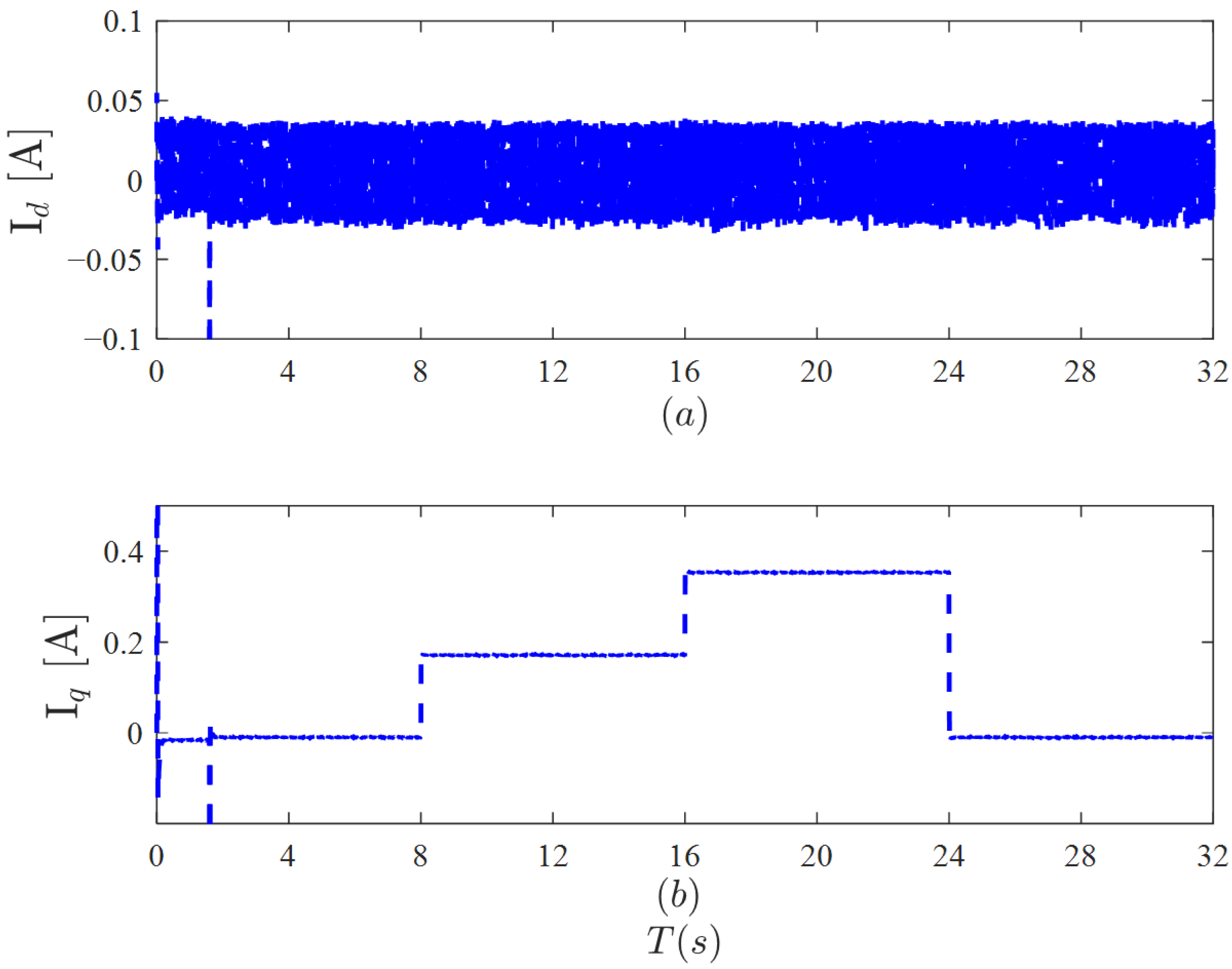
As shown in
Figure 12, when sudden loading/unloading occurs at 8 s, 16 s, and 24 s, Id remains within a certain range throughout the process and does not change with sudden loading/unloading; however, Iq changes proportionally with the load. The
-
axis current is a core parameter for motor electrical parameter identification, so ensuring high-precision, low-latency feedback of the
d-
q axis current is the core of the entire identification system. DPCC has high-precision current tracking capabilities, so the difference between the actual
-
axis current and the expected current is small, thereby ensuring high-precision feedback of the
-
axis current.
As shown in
Figure 13, before the actual speed reaches the desired speed, due to fluctuations in the
-
axis current, the identification values of
,
, and
exhibit significant errors, which persist until identification is completed around 8 s. However, after adding a 0.2 N·m load at 8 s, the
-
axis current experiences short-term feedback fluctuations, resulting in increased identification errors for all parameters, which stabilize after approximately 0.3 s. When an additional 0.2 N·m load is applied at 16 s, the fluctuations in the
-
currents cause the identification results of the parameters to exhibit overshoot for approximately 0.2 s, after which they stabilize. Finally, after the load is suddenly reduced to zero at 24 s, the identification results of the parameters fluctuate for 0.5 s before stabilizing.
6. Conclusions
To address the decline in control accuracy caused by parameter mismatch in joint-driven permanent magnet synchronous motor drive systems and enhance the control system’s disturbance rejection capability, an enhanced DPCC multi-parameter discrete system identification scheme based on LCSPC is proposed. The research findings are summarized as follows:
(1) Deriving a transient current error model from the motor model solves the problem of matrix rank deficiency during multi-parameter identification. It also reduces the loss of identification accuracy caused by parameter coupling.
(2) A control algorithm for an LCSPC was designed based on a discrete mathematical model of the motor. This algorithm has low model complexity and automatically feeds identification results back into the control system. It imposes minimal computational demands on the controller, thereby meeting cost requirements within the intelligent manufacturing sector.
(3) Both simulation analysis and experimental results demonstrate that the proposed control algorithm not only satisfies the identification requirements of low electrical parameter error and rapid convergence but also treats external disturbances as controller convergence curves during different motor operating states. Adjusting the parameters achieves high-precision motor control.
(4) Although the presented algorithm shows great potential for practical application, there are still some challenges in the control process, such as deadband output voltage compensation and DPCC accuracy.
