Article

Adaptive Backstepping Control of an Unmanned Aerial Manipulator

by
Muhammad Awais Rafique
,
Mohssen E. Elshaar
and
Alan F. Lynch
*
Department of Electrical and Computer Engineering, University of Alberta, Edmonton, AB T6G 1H9, Canada
*
Author to whom correspondence should be addressed.
Machines 2025, 13(10), 915; https://doi.org/10.3390/machines13100915
Submission received: 26 August 2025 / Revised: 27 September 2025 / Accepted: 30 September 2025 / Published: 4 October 2025
(This article belongs to the Special Issue Nonlinear Dynamics in Mechanical Systems, Automation and Control)

Abstract

This paper presents an adaptive backstepping feedback control design for an unmanned aerial manipulator (UAM) that consists of an unmanned aerial vehicle (UAV) with an attached robotic arm. The effect of the arm is treated as a disturbance force and torque, as well as a parametric uncertainty in inertial parameters. The proposed adaptive law guarantees disturbance rejection assuming constant parameters and disturbances. In practice, this assumption includes the case of fixed-arm configurations. To validate the control design, numerical simulations are performed, including a realistic pick-and-place scenario.

1. Introduction

Research on unmanned aerial vehicles (UAVs) is currently focused on expanding their capabilities for aerial manipulation. Such manipulation tasks span a wide range of applications, including payload transport [1] and non-destructive infrastructure testing [2]. Normally, aerial manipulation platforms involve some form of “arm” mounted to a UAV, typically a multirotor. The combined UAV/arm system is referred to as an unmanned aerial manipulator (UAM). Research on UAMs is currently very active, and a summary of results to date can be found in [3,4]. This paper considers a UAM consisting of a traditional underactuated multirotor UAV and two-DoF (Degree of Freedom) manipulator arm with a payload end-effector. We consider the problem of free motion control of the UAM and directly compensate for the effect of the arm’s influence. Applications include payload transport, and a pick-and-place simulation is included in this paper.
As manipulation can involve contact with the environment, some of the existing work investigates the simultaneous control of contact force and motion. Early examples of that work for a UAV with a single fixed single-link arm include [5,6,7], and more advanced work can be found in [3,4]. However, since this paper focuses on free motion control, we review existing work on that topic. We also consider work on the more complex case of multi-DoF arms. Pure motion control for multi-DoF arm UAMs can be divided into two approaches: (i) decentralized control of the UAV and arm [8,9,10,11,12,13,14,15] and (ii) centralized control of the entire UAM system [16,17,18,19,20,21,22]. The first approach generally benefits from simpler controllers, but coupling disturbances are often neglected, leading to an incomplete closed-loop analysis. The second approach normally accounts for arm/UAV coupling but can lead to complex controllers. This paper adopts the first approach by controlling the UAV center of mass (CoM) position and yaw while compensating for the effect of the arm by introducing uncertain inertial parameters and force/torque disturbances.
An example of Approach (i) includes [8], which considers a hexrotor UAV with a four-DoF arm. A disturbance observer-based design from [23] is used to control the UAV attitude dynamics. The outer loop is controlled without accounting for subsystem coupling. The work in [24] only considers the control of the outer loop using a model reference control approach. UAV mass is taken as the unknown parameter. The effect of coupling forces and torques due to the arm is not considered. In [25], arm joint states are explicitly estimated with an observer to compute disturbance torque, which are then compensated for in a quaternion-based attitude controller. More recently, ref. [26] proposed an adaptive incremental nonlinear dynamic inversion scheme, where a Kalman filter updates the control effectiveness matrix to account for arm-induced parameter variation. In contrast to the above-mentioned designs, our approach avoids arm state reconstruction, models the arm’s influence as parametric uncertainties and external disturbances, and proposes an adaptive backstepping design to guarantee UAM position and yaw trajectory tracking. We remark that the literature on robust control for bare UAVs, i.e., without an arm, is related to Approach (i), for example, disturbance rejection methods [27,28] and fractional-order sliding-mode backstepping for finite-time quadcopter stabilization [29]. Furthermore, decentralized control of slung load systems is also related to UAM motion control as the slung load is normally modeled as an unactuated two-rotational-DoF “arm” [1].
In this paper, our objective is trajectory tracking of the UAV CoM and yaw. The effect of the arm on the UAV is modeled in two ways: it adds a force and torque disturbance to the UAV and introduces parametric uncertainty e.g., arm motion alters the UAV CoM and inertia matrix. We are inspired by the work of [30,31] on bare UAV motion control. These contributions only consider force and torque disturbances, while all inertial parameters are assumed to be known. Other adaptive schemes for bare UAVs that address parametric uncertainty in inertia and mass include [32]. However, that work does not account for the disturbance wrench.
This paper is organized as follows. Section 2 presents the model of the UAM. Section 3 presents model assumptions, formulates the control problem, proposes a control design, and performs stability analysis. Numerical simulations are presented in Section 4. Finally, Section 5 concludes the paper. The proposed control is based on the first author’s thesis [33].

2. Modeling

Consider a UAM consisting of a UAV with an attached robotic arm. In this section, we present the UAV model and introduce force/torque disturbances and parametric uncertainties to model the effect of the arm. The UAV model neglects the effects of motor dynamics, rotor drag, and the rotor gyroscopic effects. The details on modeling these higher-order effects are discussed in [34,35].
Consider Figure 1. Let N denote an inertial navigation frame with basis vectors { n 1 , n 2 , n 3 } pointing north, east, and down, respectively. Let B denote a body-fixed frame whose origin coincides with the UAV center of mass (CoM). The basis vectors of B are { b 1 , b 2 , b 3 } , pointing forward, right, and downward relative to the UAV. The position of the origin of B relative to the origin of N is denoted as p R , which is expressed in N . The linear velocity of the UAV CoM is denoted as v = p ˙ R . The orientation of B relative to N is described by rotation matrix R SO ( 3 ) . The angular velocity of the UAV relative to N expressed in B is denoted as ω R 3 and the rotational kinematics is
R ˙ = R S ( ω ) ,
where
S ( x ) = 0 x 3 x 2 x 3 0 x 1 x 2 x 1 0 , x = x 1 x 2 x 3 R 3 .
The UAV input is total propeller thrust u 0 , which creates a force in the b 3 direction, and torque τ R 3 on B . Letting m denote UAV mass and J R 3 × 3 denote UAV inertia, the UAV dynamics are
m v ˙ = m g 3 F , J ω ˙ = S ( ω ) J ω + τ
where F = u R 3 , R 3 = R e 3 , e 3 = [ 0 , 0 , 1 ] , and g 3 = g e 3 is gravitational acceleration. We remark that (2) models the UAV in isolation from the arm. To account for the effect of the arm, we introduce disturbance force d f R 3 and torque d τ R 3 . Further, we consider inertial parameters a R and J as uncertain. Hence, the UAM model is taken as
(3a) p ˙ = v , (3b) v ˙ = g 3 a u R 3 + d f , (3c) R ˙ = R S ( ω ) , (3d) J ω ˙ = S ( ω ) J ω + τ + d τ .
Further details on using (3) to model the UAM are given in [33] (Sections 2.2.4 and 2.2.5).
Note that J in (3) is a positive definite symmetric matrix with six unique entries. These entries of J define the vector J v = [ J x x , J y y , J z z , J x y , J y z , J z x ] R 6 . Using J v we can re-write the S ( ω ) J ω term in (3d) as
S ( ω ) J ω = Φ ( ω ) J v ,
where
Φ ( ω ) = 0 ω 2 ω 3 ω 2 ω 3 ω 1 ω 3 ω 2 2 ω 3 2 ω 1 ω 2 ω 1 ω 3 0 ω 1 ω 3 ω 2 ω 3 ω 1 ω 2 ω 3 2 ω 1 2 ω 1 ω 2 ω 1 ω 2 0 ω 1 2 ω 2 2 ω 1 ω 3 ω 2 ω 3 .
In model (3) we take a, J v , d f and d τ as unknown constants and denote a ^ R > 0 , J ^ v R 6 , d ^ f R 3 , and d ^ τ R 3 as their estimates. Estimation errors are defined as a ˜ = a a ^ , J ˜ v = J v J ^ v , d ˜ f = d f d ^ f , and d ˜ τ = d τ d ^ τ .

3. Control Design

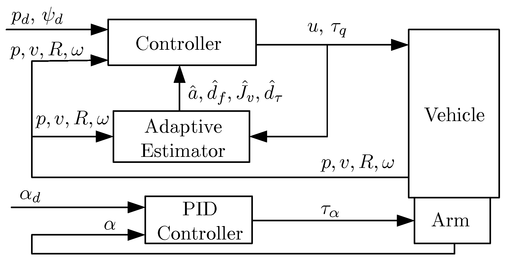
This section presents the control design for the UAM model (3). Figure 2 shows the structure of the proposed control, where the arm is controlled separately using PID control. In this figure, we denote α as the arm’s joint angles and their desired reference as α d . The proposed control compensates for the effect of the arm using an adaptive backstepping design method. The control objective is trajectory tracking for UAV CoM position p and UAV heading ψ . We first present the design for tracking p and then extend it for tracking ψ .

3.1. Position Tracking Control

The backstepping methodology performs tracking error stabilization design iteratively and subsystem-at-a-time by defining a virtual control input at each stage and using a control Lyapunov function (CLF) design procedure. In particular, we begin with the position dynamics subsystem (3a) and treat v as the virtual input to stabilize position tracking error z 1 = p p d R 3 , where p d denotes the desired position reference. As v is not a physical input and cannot be directly controlled, the next iteration of backstepping stabilizes an error state z 2 R 3 , which includes the error between the virtual input and actual velocity v. This stabilization design is achieved with a CLF treating linear acceleration as an input. Unlike the first stage of the design, now the state feedback depends on unknown parameters a and d f . This introduces parameter error terms that are compensated for adaptively at a later stage of the design. Ultimately, a key benefit of the method is that it formally accounts for uncertainty to achieve asymptotic tracking for position and yaw. Ultimately, parameters are not required to converge to their actual values, but rather, they are used to ensure position and yaw tracking occurs.
We begin the backstepping procedure by taking the time derivative of position error:
z ˙ 1 = p ˙ p ˙ d = v v d ,
where v d = p ˙ d R 3 denotes the desired linear velocity. In order to stabilize these dynamics, consider the Lyapunov function V 1 = 1 2 z 1 z 1 . Taking its time derivative gives
V ˙ 1 = z 1 z ˙ 1 = z 1 ( v v d ) . ( from ( 5 ) )
Adding and subtracting k 1 z 1 z 1 to V ˙ 1 , where k 1 > 0 is the controller gain, we obtain
V ˙ 1 = k 1 z 1 2 + z 1 ( v v d + k 1 z 1 ) .
From (6) we define the error variable z 2 = v v d + k 1 z 1 , so we can express (5) as
z ˙ 1 = k 1 z 1 + z 2 .
Now we move to the second stage of the backstepping design where we stabilize z 2 . We first take the time derivative of z 2 , and substituting (7) and the linear velocity dynamics (3b), we obtain
z ˙ 2 = g 3 a u R 3 + d f v ˙ d k 1 2 z 1 + k 1 z 2 .
Using a = a ^ + a ˜ , and d f = d ^ f + d ˜ f , we obtain
z ˙ 2 = g 3 a ^ u R 3 + d ^ f v ˙ d k 1 2 z 1 + k 1 z 2 a ˜ u R 3 + d ˜ f .
For (8) we consider the Lyapunov function V 2 = V 1 + 1 2 z 2 z 2 , whose time derivative is
V ˙ 2 = V ˙ 1 + z 2 z ˙ 2 .
Substituting into (9) for V ˙ 1 using (6) and for z ˙ 2 using (8), we obtain
V ˙ 2 = k 1 z 1 2 + z 2 ( g 3 a ^ u R 3 + d ^ f v ˙ d + ( 1 k 1 2 ) z 1 + k 1 z 2 a ˜ u R 3 + d ˜ f ) .
Adding and subtracting k 2 z 2 z 2 in the above equation, where k 2 > 0 is the controller gain, we obtain
V ˙ 2 = k 1 z 1 2 k 2 z 2 2 + z 2 ( g 3 a ^ u R 3 + d ^ f v ˙ d + ( 1 k 1 2 ) z 1 + ( k 1 + k 2 ) z 2 ) + z 2 ( d ˜ f u a ˜ R 3 ) .
We define the error state as
z 3 = g 3 a ^ u R 3 + d ^ f v ˙ d + ( 1 k 1 2 ) z 1 + ( k 1 + k 2 ) z 2 ,
and note its dependence on the estimated parameters a ^ and d ^ f . Substituting (11) into (10) gives
V ˙ 2 = k 1 z 1 2 k 2 z 2 2 + z 2 z 3 + z 2 ( d ˜ f u a ˜ R 3 ) .
Substituting (11) into (8) gives
z ˙ 2 = z 3 z 1 k 2 z 2 a ˜ u R 3 + d ˜ f .
Proceeding to the next stage of the backstepping design, we compute the time derivative of (11) as
z ˙ 3 = a ^ ˙ u R 3 a ^ u ˙ R 3 a ^ u R ˙ 3 + d ^ ˙ f v ¨ d + ( 1 k 1 2 ) z ˙ 1 + ( k 1 + k 2 ) z ˙ 2 .
Substituting (7) and (13) into the last equation, we obtain
z ˙ 3 = a ^ ˙ u R 3 a ^ u ˙ R 3 a ^ u R S ( ω ) e 3 + d ^ ˙ f v ¨ d + ( 1 k 1 2 ) ( k 1 z 1 + z 2 ) + ( k 1 + k 2 ) ( z 3 z 1 k 2 z 2 a ˜ u R 3 + d ˜ f ) .
Rearranging this expression gives
z ˙ 3 = a ^ ˙ u R 3 a ^ u ˙ R 3 a ^ u R S ( ω ) e 3 + d ^ ˙ f v ¨ d + ( k 1 3 k 2 2 k 1 ) z 1 + ( 1 k 2 ( k 1 + k 2 ) k 1 2 ) z 2 + ( k 1 + k 2 ) z 3 ( k 1 + k 2 ) a ˜ u R 3 + ( k 1 + k 2 ) d ˜ f .
For the above dynamics, consider the Lyapunov function V 3 = V 2 + 1 2 z 3 z 3 . Taking the time derivative of V 3 and using (10), we obtain
V ˙ 3 = k 1 z 1 2 k 2 z 2 2 + z 2 z 3 + z 2 ( d ˜ f u a ˜ R 3 ) + z 3 z ˙ 3 .
Substituting (14) into the last equation leads to
V ˙ 3 = k 1 z 1 2 k 2 z 2 2 + z 3 ( z 2 a ^ ˙ u R 3 a ^ u ˙ R 3 a ^ u R S ( ω ) e 3 + d ^ ˙ f v ¨ d + ( k 1 3 k 2 2 k 1 ) z 1 + ( 1 k 2 ( k 1 + k 2 ) k 1 2 ) z 2 + ( k 1 + k 2 ) z 3 ( k 1 + k 2 ) a ˜ u R 3 + ( k 1 + k 2 ) d ˜ f ) a ˜ z 2 u R 3 + d ˜ f z 2 .
Adding and subtracting k 3 z 3 z 3 from the last expression, where k 3 > 0 is the controller gain, and simplifying gives
V ˙ 3 = k 1 z 1 2 k 2 z 2 2 k 3 z 3 2 + z 3 ( a ^ ˙ u R 3 a ^ u ˙ R 3 a ^ u R S ( ω ) e 3 + d ^ ˙ f v ¨ d + ( k 1 3 k 2 2 k 1 ) z 1 + ( 2 k 2 ( k 1 + k 2 ) k 1 2 ) z 2 + ( k 1 + k 2 + k 3 ) z 3 ) + ( d ˜ f a ˜ u R 3 ) ( z 2 + ( k 1 + k 2 ) z 3 ) .
In order to simplify this expression, we define
σ 1 = ( k 1 3 k 2 2 k 1 ) z 1 + ( 2 k 2 ( k 1 + k 2 ) k 1 2 ) z 2 + ( k 1 + k 2 + k 3 ) z 3 v ¨ d ,
σ 2 = z 2 + ( k 1 + k 2 ) z 3 .
Now, consider a modified Lyapunov function:
V 3 b = V 3 + 1 2 λ a ˜ 2 + 1 2 k d f d ˜ f d ˜ f ,
where k d f > 0 , λ > 0 are controller gains. The time derivative of V 3 b is
V ˙ 3 b = k 1 z 1 2 k 2 z 2 2 k 3 z 3 2 + z 3 ( a ^ ˙ u R 3 a ^ u ˙ R 3 a ^ u R S ( ω ) e 3 + d ^ ˙ f + σ 1 ) + ( d ˜ f a ˜ u R 3 ) σ 2 + 1 λ a ˜ a ˜ ˙ + 1 k d f d ˜ f d ˜ ˙ f .
Since d f is constant, we have d ˜ ˙ f = d ^ ˙ f . Hence, (17) becomes
V ˙ 3 b = k 1 z 1 2 k 2 z 2 2 k 3 z 3 2 + z 3 ( a ^ ˙ u R 3 a ^ u ˙ R 3 a ^ u R S ( ω ) e 3 + d ^ ˙ f + σ 1 ) + a ˜ a ˜ ˙ λ u R 3 σ 2 d ˜ f d ^ ˙ f k d f σ 2 .
Adding and subtracting k d f z 3 σ 2 yields
V ˙ 3 b = k 1 z 1 2 k 2 z 2 2 k 3 z 3 2 + z 3 ( a ^ ˙ u R 3 a ^ u ˙ R 3 a ^ u R S ( ω ) e 3 + d ^ ˙ f k d f σ 2 + k d f σ 2 + σ 1 ) + a ˜ a ˜ ˙ λ u R 3 σ 2 d ˜ f d ^ ˙ f k d f σ 2 ,
and simplification gives
V ˙ 3 b = k 1 z 1 2 k 2 z 2 2 k 3 z 3 2 + z 3 ( a ^ ˙ u R 3 a ^ u ˙ R 3 a ^ u R S ( ω ) e 3 + σ 1 + k d f σ 2 ) + ( d ˜ f k d f z 3 ) σ 2 d ^ ˙ f k d f + a ˜ a ˜ ˙ λ u R 3 σ 2 .
Observe that
σ 1 + k d f σ 2 = R R ( σ 1 + k d f σ 2 ) = R I R ( σ 1 + k d f σ 2 ) = R ( I e 3 e 3 + e 3 e 3 ) R ( σ 1 + k d f σ 2 ) = R ( I e 3 e 3 ) R + R 3 R 3 ( σ 1 + k d f σ 2 ) .
Hence,
V ˙ 3 b = k 1 z 1 2 k 2 z 2 2 k 3 z 3 2 + z 3 [ a ^ ˙ u R 3 a ^ u ˙ R 3 + R 3 R 3 ( σ 1 + k d f σ 2 ) a ^ u R S ( ω ) e 3 + R ( I e 3 e 3 ) R ( σ 1 + k d f σ 2 ) ] + ( d ˜ f k d f z 3 ) σ 2 d ^ ˙ f k d f + a ˜ a ˜ ˙ λ u R 3 σ 2 .
Factoring out R 3 from the first three terms inside the square brackets and equating them to zero defines a control law for u. That is, we let
a ^ u ˙ + a ^ ˙ u = R 3 ( σ 1 + k d f σ 2 ) .
Therefore,
V ˙ 3 b = k 1 z 1 2 k 2 z 2 2 k 3 z 3 2 + z 3 R ( a ^ u S ( ω ) e 3 + ( I e 3 e 3 ) R ( σ 1 + k d f σ 2 ) ) + ( d ˜ f k d f z 3 ) σ 2 d ^ ˙ f k d f + a ˜ a ˜ ˙ λ u R 3 σ 2 .
We define ω d R 3 as the desired angular velocity. The term a ^ u S ( ω ) e 3 in (20) can be interpreted as a virtual control, whose desired value is taken as
a ^ u S ( ω d ) e 3 = ( I e 3 e 3 ) R ( σ 1 + k d f σ 2 ) .
Since S ( ω d ) e 3 = S ( e 3 ) ω d , the last equation can be rewritten as
a ^ u S ( e 3 ) ω d = ( I e 3 e 3 ) R ( σ 1 + k d f σ 2 ) .
Extracting individual components of ω d = ω d 1 , ω d 2 , ω d 3 , we have
ω d 1 = e 2 a ^ u ( I e 3 e 3 ) R ( σ 1 + k d f σ 2 ) = R 2 ( σ 1 + k d f σ 2 ) / ( a ^ u ) ,
ω d 2 = e 1 a ^ u ( I e 3 e 3 ) R ( σ 1 + k d f σ 2 ) = R 1 ( σ 1 + k d f σ 2 ) / ( a ^ u ) ,
where R 1 and R 2 R 3 are the first and second columns of R. We can now rewrite (20) as
V ˙ 3 b = k 1 z 1 2 k 2 z 2 2 k 3 z 3 2 + z 3 a ^ u R S ( e 3 ) ω ω d + ( d ˜ f k d f z 3 ) σ 2 d ^ ˙ f k d f + a ˜ a ˜ ˙ λ u R 3 σ 2
Now, consider the following parameter update laws:
d ^ ˙ f = k d f σ 2 , a ^ ˙ = λ u R 3 σ 2 ,
Substituting these adaptive laws into (24), we have
V ˙ 3 b = k 1 z 1 2 k 2 z 2 2 k 3 z 3 2 + z 3 a ^ u R S ( e 3 ) ω ω d .
Let the error in angular velocity be z 4 = ω ω d . Using (3d), we can write
J z ˙ 4 = J ω ˙ J ω ˙ d = S ( ω ) J ω + τ + d τ J ω ˙ d .
Define
ω ¯ d = 1 a ^ u ( a ^ ˙ u + a ^ u ˙ ) ( I e 3 e 3 T ) ω d + 1 a ^ u S ( e 3 ) S ( ω ) R T ( σ 1 + k d f σ 2 ) 1 a ^ u S ( e 3 ) R T ( σ ¯ 1 + k d f σ ¯ 2 ) + ω ˙ d 3 e 3 ,
Using J v instead of J, we have
J ω ¯ d = Ψ ( ω ¯ d ) J v ,
where
Ψ ( ω ¯ d ) = ω ¯ d 1 0 0 ω ¯ d 2 0 ω ¯ d 3 0 ω ¯ d 2 0 ω ¯ d 1 ω ¯ d 3 0 0 0 ω ¯ d 3 0 ω ¯ d 2 ω ¯ d 1 .
Therefore, (27) can be rewritten as
J z ˙ 4 = ( Φ ( ω ) + Ψ ( ω ˙ d ) ) J v + τ + d τ .
Substituting J v = J ^ v + J ˜ v and d τ = d ^ τ + d ˜ τ into (29) gives
J z ˙ 4 = ( Φ ( ω ) + Ψ ( ω ˙ d ) ) ( J ^ v + J ˜ v ) + τ + d ^ τ + d ˜ τ .
Now, consider the Lyapunov function
V 4 = V 3 b + 1 2 z 4 J z 4 + 1 2 k d τ d ˜ τ d ˜ τ + 1 2 J ˜ v Γ 1 J ˜ v ,
where k d τ > 0 and Γ > 0 R 6 × 6 are controller gains. Differentiating (31) with respect to time gives
V ˙ 4 = V ˙ 3 b + z 4 J z ˙ 4 + 1 k d τ d ˜ τ d ˜ ˙ τ + J ˜ v Γ 1 J ˜ ˙ v .
Substituting (26) and (30) into (32) gives
V ˙ 4 = k 1 z 1 2 k 2 z 2 2 k 3 z 3 2 + z 3 a ^ u R S ( e 3 ) z 4 + z 4 ( ( Φ ( ω ) + Ψ ( ω ˙ d ) ) ( J ^ v + J ˜ v ) + τ + d ^ τ + d ˜ τ ) + 1 k d τ d ˜ τ d ˜ ˙ τ + J ˜ v Γ 1 J ˜ ˙ v .
Let k 4 > 0 be the controller gain. By adding and subtracting k 4 z 4 z 4 in the above expression and factoring z 4 , we obtain
V ˙ 4 = k 1 z 1 2 k 2 z 2 2 k 3 z 3 2 k 4 z 4 2 + z 4 ( a ^ u S ( e 3 ) R z 3 + k 4 z 4 ( Φ ( ω ) + Ψ ( ω ˙ d ) ) J ^ v + τ + d ^ τ ) + J ˜ v ( Γ 1 J ˜ ˙ v ( Φ ( ω ) + Ψ ( ω ˙ d ) ) z 4 ) + d ˜ τ ( 1 k d τ d ˜ ˙ τ + z 4 ) .
At this point, we assign the expression for input τ :
τ = a ^ u S ( e 3 ) R z 3 k 4 z 4 + ( Φ ( ω ) + Ψ ( ω ˙ d ) ) J ^ v d ^ τ ,
and define the parameter update laws
J ^ ˙ v = Γ ( Φ ( ω ) + Ψ ( ω ˙ d ) ) z 4 , d ^ ˙ τ = k d τ z 4 .
Using d ˜ ˙ τ = d ^ τ and J ˜ ˙ v = J ^ v since J v and d τ are constants and substituting (35) and (36) into (34), we obtain
V ˙ 4 = k 1 z 1 2 k 2 z 2 2 k 3 z 3 2 k 4 z 4 2 ,
which is negative semi-definite.
Theorem 1. 
Consider the UAM dynamics (3) and assume that a ˙ = 0 , d ˙ f = 0 , d ˙ τ = 0 , J ˙ v = 0 , and u > 0 , a ^ > 0 . Given a smooth time-varying trajectory p d ( t ) , feedback law (35) with k 1 , k 2 , k 3 , k 4 > 0 , and parameter update laws (25) and (36) with k d f , k d τ , λ , and Γ > 0 , then the tracking error z = [ z 1 , z 2 , z 3 , and   z 4 ] is globally asymptotically convergent to 0 and the parameter estimates a ^ , d ^ f , d ^ τ and J ^ v are bounded.
Proof. 
Consider the quadratic positive definite Lyapunov function V 4 in (31). According to [36] (Lemma 4.3), there exist two positive definite functions that form the lower and upper bounds of V 4 . The time derivative of V 4 after substitution of (25), (35), and (36) is a negative semi-definite function. Using Barbalat’s lemma [36] (Theorem 8.4), we can conclude that z 0 as t , and the parameter and disturbance estimates a ^ , d ^ f , d ^ τ , and J ^ v are bounded. Since V 4 is radially unbounded, we conclude that the equilibrium point z = 0 is globally asymptotically stable. □

3.2. Position and Yaw Tracking Control

Thus far, the adaptive backstepping control design has achieved trajectory tracking for p. Since the UAV has four control inputs, we can extend the control to track UAV heading, which is practically relevant for manipulation tasks. We identify UAV heading with yaw angle ψ ( π , π ] . Let the desired UAV yaw trajectory be ψ d ( π , π ] and define the tracking error as z ψ = ψ ψ d . Let
V ψ = 1 2 z ψ 2 .
Thus,
V ˙ ψ = z ψ z ˙ ψ = z ψ ( ψ ˙ ψ ˙ d ) .
The rotational kinematics (1) can be expressed in terms of ZYX or 321 Euler angles by substituting the expression for R as a function of Euler angles into that equation. We obtain
ω = W ( θ , ϕ ) η ˙
where η = [ ϕ , θ , ψ ] , ϕ denotes roll, and θ denotes pitch, and
W ( θ , ϕ ) = 1 0 s θ 0 c ϕ s ϕ c θ 0 s ϕ c ϕ c θ
where c θ = cos θ and s θ = sin θ . Since | W | = c θ , W is invertible for θ ± π / 2 , and the rotational kinematics (41) can be written as
η ˙ = W ( θ , ϕ ) 1 ω
Hence, taking the third component of (40), the yaw rate can be expressed in terms of the angular velocity as ψ ˙ = e 3 W 1 ( θ , ϕ ) ω . The inverse of W is
W 1 ( θ , ϕ ) = 1 t θ s ϕ t θ c ϕ 0 c ϕ s ϕ 0 s ϕ c θ c ϕ c θ
where t θ = tan θ Therefore, we can write (39) as
V ˙ ψ = z ψ z ˙ ψ = z ψ ( e 3 W 1 ω ψ ˙ d )
Adding and subtracting k ψ z ψ 2 , where k ψ > 0 is the control gain, gives
V ˙ ψ = k ψ z ψ 2 + z ψ ( k ψ z ψ + e 3 W 1 ω ψ ˙ d )
In order to define the third component of the desired angular velocity ω d , we use
e 3 W 1 ω d = s ϕ c θ ω d 2 + c ϕ c θ ω d 3 = k ψ z ψ + ψ ˙ d
Solving this equation for ω d 3 gives
ω d 3 = c θ c ϕ ( k ψ z ψ + ψ ˙ d + s ϕ c θ ω d 2 ) = c θ c ϕ ( k ψ z ψ + ψ ˙ d ) + t ϕ ω d 2 ,
where ω d 2 is given in (23). Substituting (43) into (42) results in
V ˙ ψ = k ψ z ψ 2 + z ψ ( e 3 W 1 ( ω ω d ) ) = k ψ z ψ 2 + z ψ ( e 3 W 1 z 4 ) = k ψ z ψ 2 + z 4 z ψ W 1 e 3 .
We are now ready to state the stability result for the position–yaw tracking controller.
Theorem 2. 
Consider the UAM dynamics (3) and assume that a ˙ = 0 , d ˙ f = 0 , d ˙ τ = 0 , J ˙ v = 0 , u > 0 , and a ^ > 0 . Given a smooth trajectory p d ( t ) , ψ d ( t ) , control (19) and
τ = z ψ W T e 3 a ^ u S ( e 3 ) R z 3 k 4 z 4 + ( Φ ( ω ) + Ψ ( ω ˙ d ) ) J ^ v d ^ τ
with k 1 , k 2 , k 3 , k 4 > 0 and parameter update laws (25) and (36) with k d f , k d τ , and λ , Γ > 0 , then the tracking error z = [ z 1 , z 2 , z 3 , z 4 , z ψ ] converges asymptotically to 0 while the estimates a ^ , d ^ f , d ^ τ and J ^ v are bounded.
Proof. 
Consider the Lyapnouv function V 4 , ψ = V 4 + V ψ  with time derivative
V ˙ 4 , ψ = V ˙ 4 + V ˙ ψ .
Substituting for V ˙ 4 using (34) and using parameter update laws (36) and the expression for V ˙ ψ in (45) gives
V ˙ 4 , ψ = k 1 z 1 2 k 2 z 2 2 k 3 z 3 2 k 4 z 4 2 k ψ z ψ 2 + z 4 z ψ W 1 e 3 + z 4 ( a ^ u S ( e 3 ) R z 3 + k 4 z 4 ( Φ ( ω ) + Ψ ( ω ˙ d ) ) J ^ v + τ + d ^ τ )
Substituting (46) gives
V ˙ 4 , ψ = k 1 z 1 2 k 2 z 2 2 k 3 z 3 2 k 4 z 4 2 k ψ z ψ 2
which is negative semi-definite. As in the proof of Theorem 1, we conclude that z 0 as t  and the parameters remain bounded. □
Remark 1. 
The controllers presented in (35) and (46) depend on ω ˙ d ; however, the above derivation gives an expression for ω d . The value of ω ˙ d can be obtained numerically from the low-pass-filtered finite difference. The algebraic expression for ω d depends on d ˜ f , which is not known. In addition, the unknown inertia vector J v in the angular velocity dynamics complicates the stability proof. Work in [33] provides further details for alternate solutions to this problem.
Other underactuated UAMs, which are based on traditional helicopters [37,38] or hexacopters [8], could be controlled using the proposed scheme with no modification other than to the mixing subsystem that maps the four-dimensional force/torque to the physical inputs. For example, this mixing is built into the PX4 autopilot [39]. Furthermore, the type of manipulator arm is not important as its dynamics are treated as a disturbance or parameter uncertainty. Hence, the approach could be applied to UAMs such as [8], where a hexarotor carries a four-DoF arm, or [9], which considers a quadrotor with a three-DoF arm.

4. Simulation Results

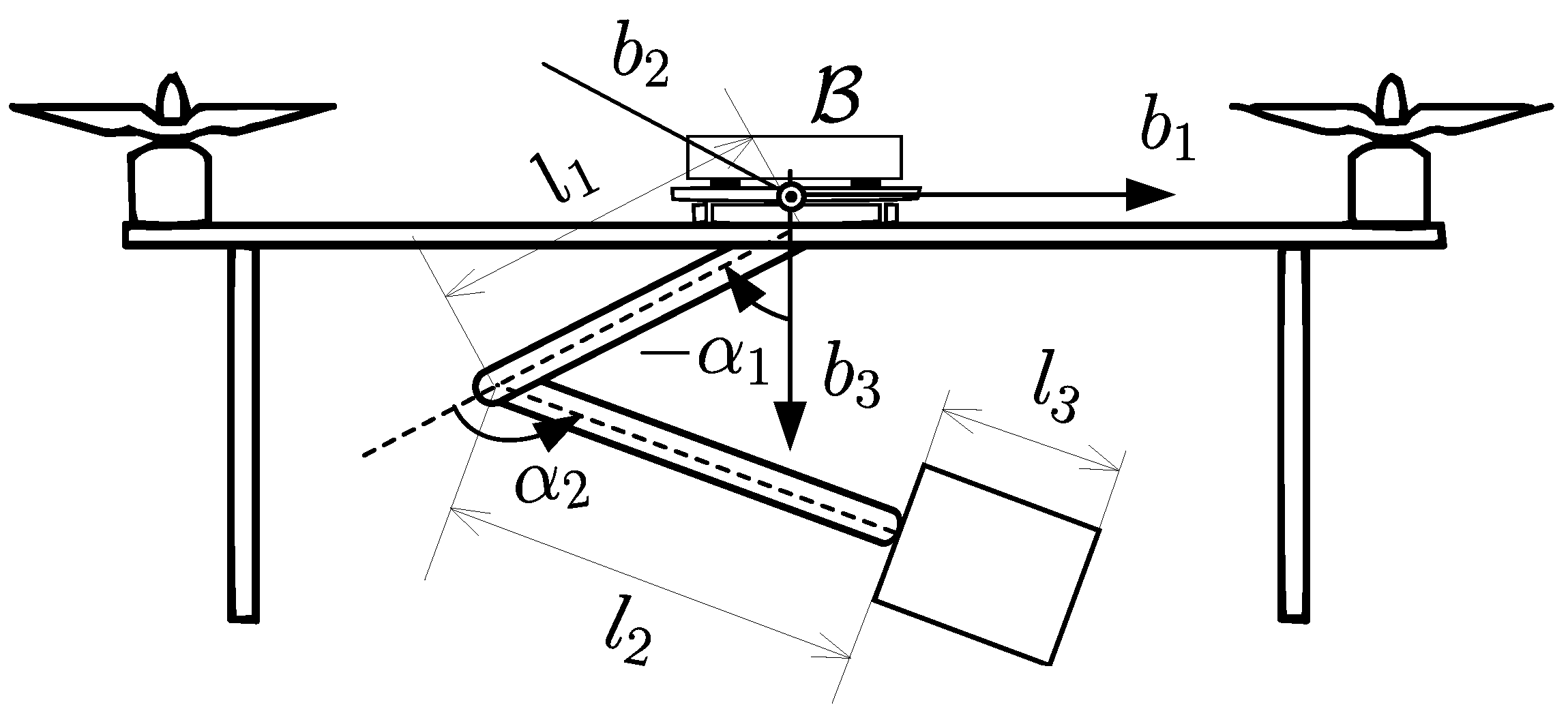
This section presents numerical simulations using MATLAB R2024b and the Simscape Multibody toolbox to validate our control design. The files used to generate these simulations can be found at https://github.com/ANCL/UAM_control (accessed on 1 June 2025). A multibody simulation is necessary to avoid the complexity of simulating the closed loop in a traditional state-space format. The UAM used in the simulation is shown in Figure 3. The arm is a three-link, two-DoF manipulator with two revolute joints. Link 1 is attached to the CoM of the UAV and rotates in the b 1 b 3 plane about the origin of B . Link 2 is a revolute joint, which also rotates in the same plane. Link 3 is fixed to Link 2 and acts as a payload mass. The UAV and arm parameters are given in Table 1 and Table 2 respectively. We consider three simulations: a figure-of-eight desired position with fixed and moving arm cases and a pick-and-place operation.

4.1. Figure-of-Eight Reference Trajectory

For the figure-of-eight trajectory, in addition to the coupling forces and torques due to the arm, we consider a constant external disturbance force of [ 0.2 , 0.2 , 0.2 ] N } acting at the UAV CoM. The controller gains used for all simulations are given in Table 3. The initial conditions are p ( 0 ) = [ 2 , 2 , 0 ]   m , v ( 0 ) = 0   m s 1 , η ( 0 ) = 0   rad and ω ( 0 ) = 0 rad s 1 , a ^ ( 0 ) = 1 0.7 m , and J ^ v ( 0 ) = 0.6 J v , i.e., we consider a 30% error in mass and a 40% error in inertia initially. The initial conditions for the disturbances are d ^ f ( 0 ) = d ^ τ ( 0 ) = 0 .
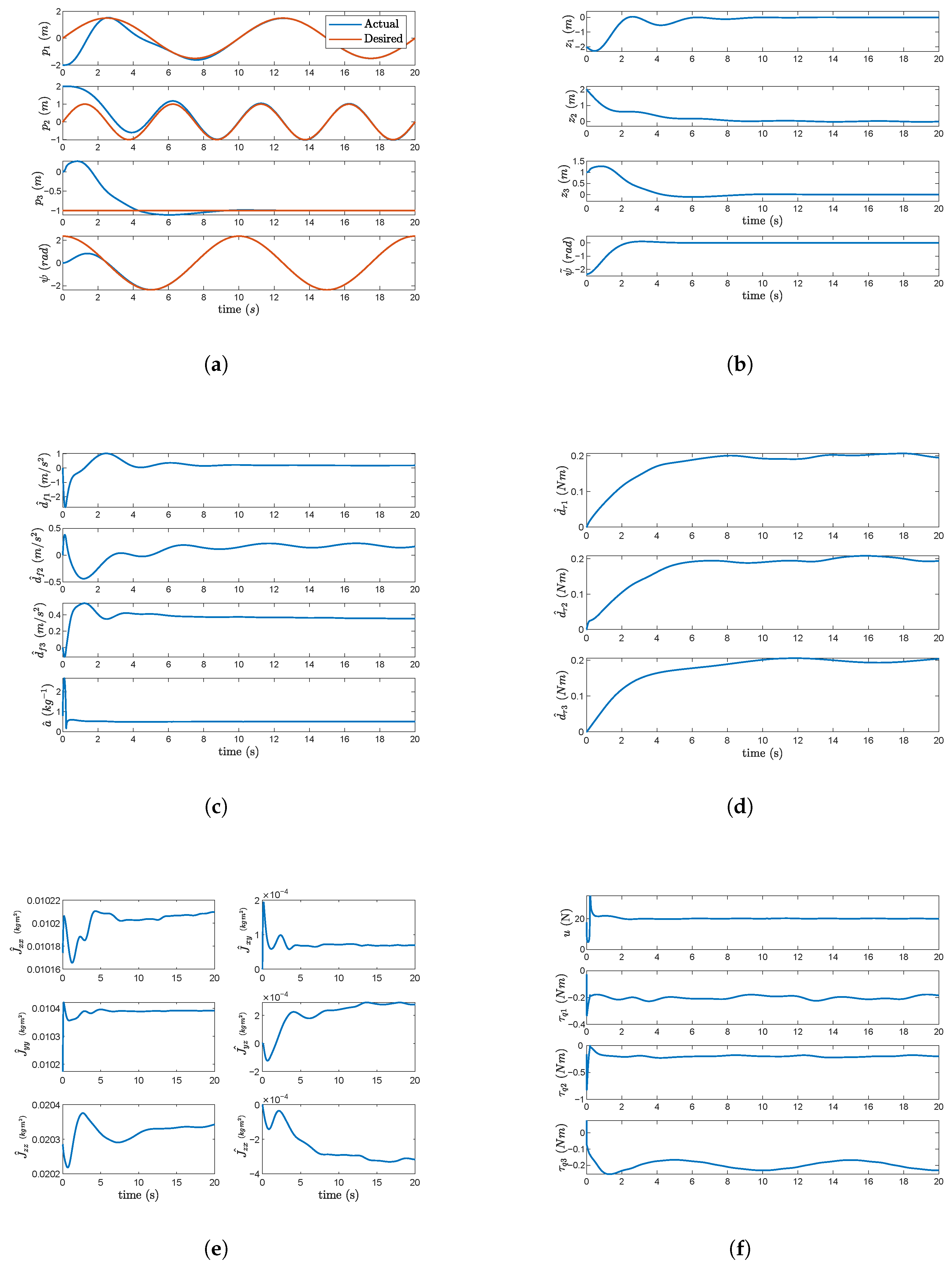
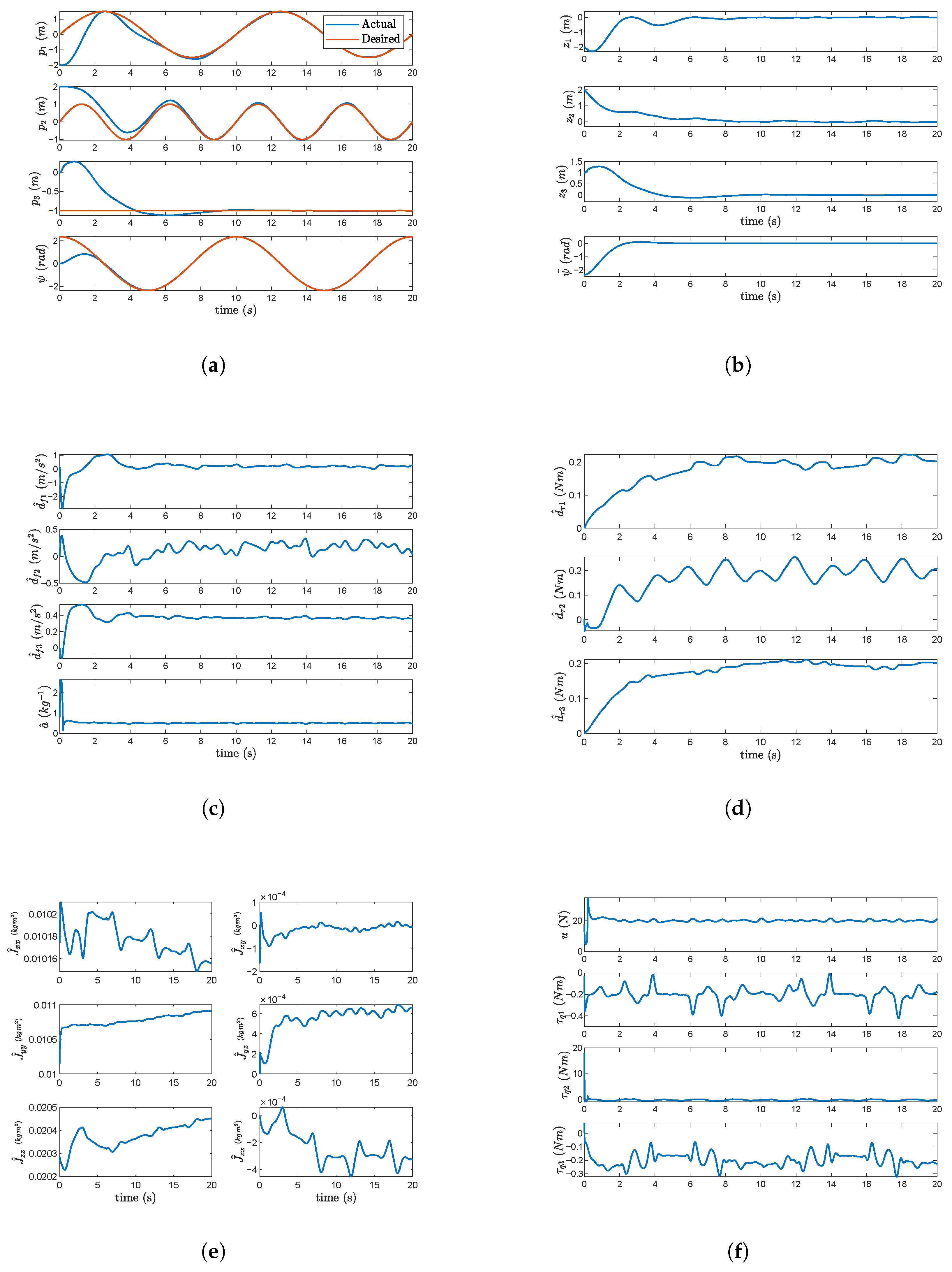
Figure 4a–f present the simulation results for the fixed-arm case α 1 = α 2 = 0 , where the arm is locked in the b 3 direction. The position tracking errors in Figure 4b converge to a small neighborhood of 0. The estimates a ^ , d ^ f , d ^ τ , and J ^ v remain bounded. These estimates are shown in Figure 4c–e. We observe that in steady state these parameters are time-varying due to the time-varying reference trajectory. That is, the UAV must vary its attitude to track the position trajectory, and this creates a time-varying disturbance. Figure 4f shows the control inputs. The simulation results for the moving-arm case are shown in Figure 5a–f. The arm motion is given by α 1 ( t ) = π 3 sin ( π t ) and α 2 ( t ) = 3 π 2 t . Figure 5b presents the UAV CoM position errors, which remain small with only mild oscillations around the origin. Compared with the fixed-arm case, the steady-state error is somewhat larger but still acceptable from a practical standpoint. The estimated parameters and disturbances remain bounded and time-varying in steady state, with significant variation, as shown in Figure 5c–e. Figure 5f shows the control inputs.

4.2. Adaptation Comparison with Fixed-Parameter Case

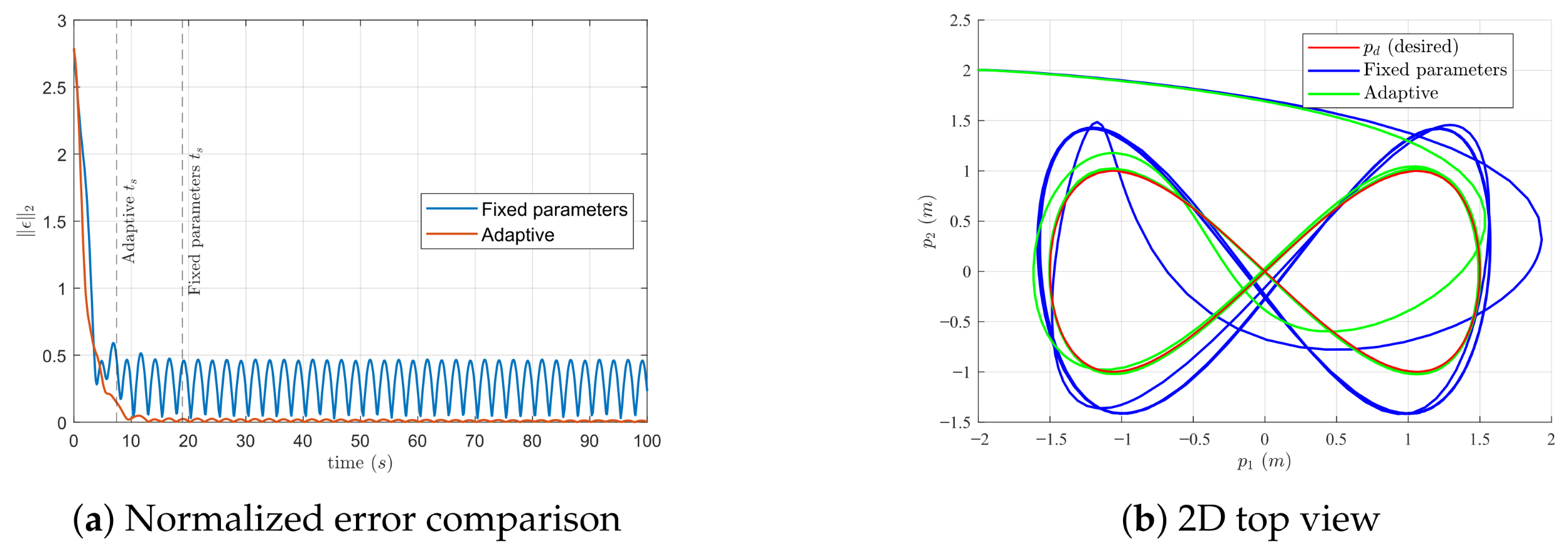
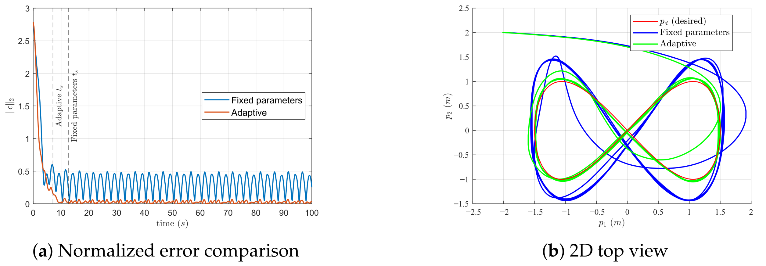
This section assesses the performance of the proposed method compared to a method in the existing literature. In order to make a sensible and fair comparison, we choose to compare it with the design in [30]. This method shares certain elements with the proposed design. Both approaches use a backstepping methodology, but [30] does not adapt to inertial parameters a and J. In the adaptive case, all update laws (25) and (36) are active. In the fixed-parameter case, the updates for a ^ and J ^ v are disabled, i.e., a ^ ˙ = 0 and J ^ ˙ v = 0 , so these estimates remain at their initial values. The disturbance-related estimates d ^ f and d ^ τ continue to adapt, ensuring disturbance rejection. Both controllers use identical gains that are shown in Table 3.
Performance is evaluated using the settling time t s and the steady-state nRMSE of the combined error norm e. For periodic responses, t s is defined as the time taken to reach 5 % of the steady state. The tracking error is normalized using the desired trajectory with
ε = p 1 p d 1 max ( p d 1 ) min ( p d 1 ) p 2 p d 2 max ( p d 2 ) min ( p d 2 ) p 3 p d 3 max ( p d 3 ) min ( p d 3 ) ψ ψ d max ( ψ d ) min ( ψ d ) R 4 ,
and we compute its norm
e = ε 2 .
The steady-state nRMSE is computed over the interval [ t s , T ] as
nRMSE = 1 T t s t s T e 2 d t .
The proposed method reduces t s from 18.93 s to 7.45 s (approximately 61% faster) and nRMSE from 33.3% to 1.4% (approximately 96% reduction) in the fixed-arm case (Table 4, Figure 6a). In the moving-arm configuration, the improvements are similar: t s drops from 12.60 s to 7.04 s and nRMSE from 33.6% to 2.0% (Table 5, Figure 7a). These results demonstrate that adaptation consistently accelerates convergence and tightens tracking accuracy under the added complexity of arm dynamics.

4.3. Robustness to Parameter Variation

To evaluate robustness, ten simulations were performed with random UAM parameters and disturbances. The parameter range considered was ± 30 % for masses, ± 40 % for principal inertias, and ± 15 % for link lengths. Disturbances were randomized within ± 250 % of their nominal value. The adaptive controller was applied with the same fixed gains (Table 3) for all runs. Table 6 summarizes the results. All simulations converged within 6–8 s, with steady-state normalized RMSEs consistently around 1–3%. The variation across simulations was small: the standard deviation of t s was less than 1 s and the standard deviation of steady-state nRMSE remained below 0.3 % . These results indicate that, even under parameter uncertainty and different disturbance levels, the adaptive controller achieves robust tracking performance.

4.4. Pick-and-Place

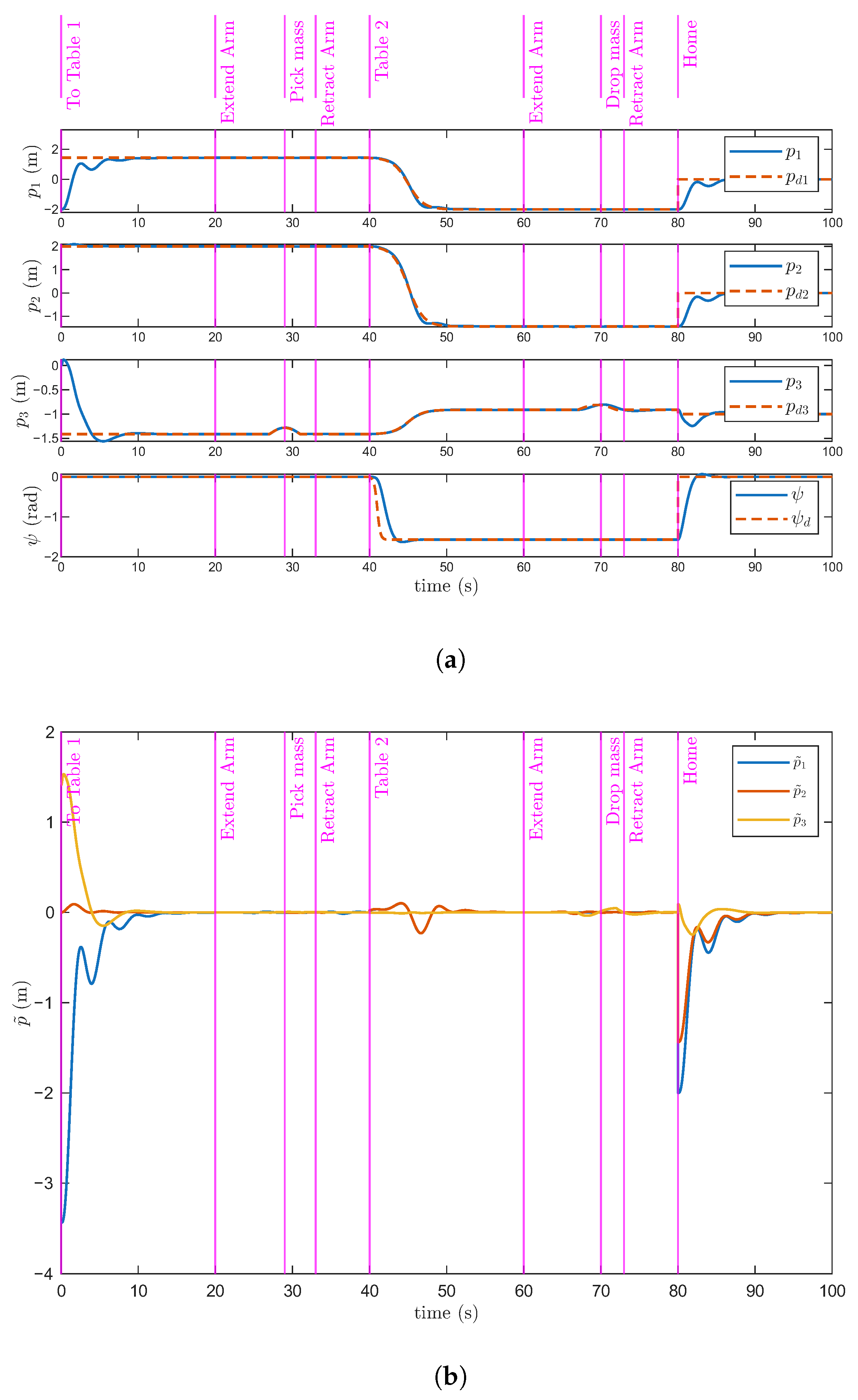
We now present a practical pick-and-place motion, where the UAM takes off to a target position, extends its arm, picks up a payload, flies it to a desired location, and places the payload at the desired location. Multiple “table” landmarks are created in MATLAB Simscape Multibody that correspond to the various locations of the task. A small cubic payload of mass 0.1   k g and dimension 0.1   m is attached to the end-effector. The UAV CoM start location is p ( 0 ) = [ 2 , 2 , 0 ]   m . The first and second desired UAV CoM positions and yaws are denoted as Location 1 and Location 2, respectively. Location 1 is p d 1 = [ 1.4379 , 2.0000 , 1.4121 ]   m , ψ d 1 = 0   rad , and Location 2 is p d 2 = [ 2 , 1.4379 , 0.9121 ]   m , ψ d 2 = π / 2   rad . When picking up the payload, the UAV position is lowered using a function h ( t 0 ) = [ 0 , 0 , 0.1 sin ( π ( t 0 ) / 5 ) ) ] . Table 7 shows the desired trajectory for the UAV and arm. The Home configuration for the arm is selected to be α 1 = π / 4 , α 2 = 3 π / 4 . The desired values of p and ψ are shown in Figure 8a. The position errors are given in Figure 8b. The figures label each phase of the task. Evidently, the figures show that tracking error is asymptotically convergent, as expected by the theory. In this task, the assumptions of Theorem 2 hold as the desired position, and the arm configuration is eventually constant. Hence, this simulation case illustrates a practical case where assumptions hold.

5. Conclusions

In this paper, we have presented a control design for a UAM consisting of a UAV and a multi-DoF robotic arm. The design is based on a UAV model that accounts for the arm’s effect by including torque and force disturbances and parametric uncertainty. An adaptive backstepping control law is presented that achieves UAV CoM position and yaw tracking when disturbances and parameters are constant. Numerical simulations demonstrate that bounded tracking error results when disturbances and parameters are varying. A practical pick-and-place task illustrates a case where tracking error converges. Future work will involve indoor and outdoor experimental validation of the control with an open-source platform, as in [40]. An intermediate step for this validation is software-in-the-loop testing that includes various non-idealities such as actuator saturation, sampling effects, state estimation errors, and rotor drag [41].

Author Contributions

Methodology, M.A.R. and A.F.L.; Software, M.A.R. and M.E.E.; Validation, M.E.E.; Formal analysis, M.A.R. and A.F.L.; Writing—review & editing, A.F.L. and M.E.E.; Visualization, M.E.E. All authors have read and agreed to the published version of the manuscript.

Funding

This research was funded by the Natural Sciences and Engineering Council of Canada (NSERC) Grant RGPIN-2023-04156 and The Government of Alberta Major Innovation Fund Grant No. MIF-23-009.

Data Availability Statement

The data presented in this study are openly available at [https://github.com/ANCL/UAM_control], accessed on 1 June 2025.

Conflicts of Interest

The authors declare no conflicts of interest.

References

  1. Villa, D.K.D.; Brandão, A.S.; Sarcinelli-Filho, M. A Survey on Load Transportation Using Multirotor UAVs. J. Intell. Robot. Syst. 2020, 98, 267–296. [Google Scholar] [CrossRef]
  2. Watson, R.J.; Pierce, S.G.; Kamel, M.; Zhang, D.; MacLeod, C.N.; Dobie, G.; Bolton, G.; Dawood, T.; Nieto, J. Deployment of Contact-Based Ultrasonic Thickness Measurements Using Over-Actuated UAVs. In European Workshop on Structural Health Monitoring, Proceedings of the European Workshop on Structural Health Monitoring (EWSHM 2020), Palermo, Italy, 6–9 July 2020; Lecture Notes in Civil Engineering; Rizzo, P., Milazzo, A., Eds.; Springer: Cham, Switzerland, 2021; Volume 127, pp. 683–694. [Google Scholar] [CrossRef]
  3. Bonyan Khamseh, H.; Janabi-Sharifi, F.; Abdessameud, A. Aerial manipulation—A literature survey. Robot. Auton. Syst. 2018, 107, 221–235. [Google Scholar] [CrossRef]
  4. Ollero, A.; Tognon, M.; Suarez, A.; Lee, D.; Franchi, A. Past, Present, and Future of Aerial Robotic Manipulators. IEEE Trans. Robot. 2022, 38, 626–645. [Google Scholar] [CrossRef]
  5. Albers, A.; Trautmann, S.; Howard, T.; Nguyen, T.A.; Frietsch, M.; Sauter, C. Semi-autonomous flying robot for physical interaction with environment. In Proceedings of the IEEE Conference on Robotics, Automation and Mechatronics, Singapore, 28–30 June 2010; pp. 441–446. [Google Scholar] [CrossRef]
  6. Nguyen, H.; Lee, D. Hybrid force/motion control and internal dynamics of quadrotors for tool operation. In Proceedings of the IEEE/RSJ International Conference on Intelligent Robots and Systems (IROS), Tokyo, Japan, 3–7 November 2013; pp. 3458–3464. [Google Scholar] [CrossRef]
  7. Mersha, A.Y.; Stramigioli, S.; Carloni, R. Variable impedance control for aerial interaction. In Proceedings of the IEEE/RSJ International Conference on Intelligent Robots and Systems (IROS), Chicago, IL, USA, 14–18 September 2014; pp. 3435–3440. [Google Scholar] [CrossRef]
  8. Kim, S.; Choi, S.; Kim, H.; Shin, J.; Shim, H.; Kim, H.J. Robust Control of an Equipment-Added Multirotor Using Disturbance Observer. IEEE Trans. Autom. Control 2018, 26, 1524–1531. [Google Scholar] [CrossRef]
  9. Jimenez-Cano, A.E.; Martin, J.; Heredia, G.; Ollero, A.; Cano, R. Control of an aerial robot with multi-link arm for assembly tasks. In Proceedings of the IEEE International Conference on Robotics and Automation (ICRA), Karlsruhe, Germany, 6–10 May 2013; pp. 4916–4921. [Google Scholar] [CrossRef]
  10. Korpela, C.; Orsag, M.; Pekala, M.; Oh, P. Dynamic stability of a mobile manipulating unmanned aerial vehicle. In Proceedings of the IEEE International Conference on Robotics and Automation (ICRA), Karlsruhe, Germany, 6–10 May 2013; pp. 4922–4927. [Google Scholar] [CrossRef]
  11. Kannan, S.; Olivares-Mendez, M.A.; Voos, H. Modeling and Control of Aerial Manipulation Vehicle with Visual sensor. IFAC Proc. Vol. 2013, 46, 303–309. [Google Scholar] [CrossRef]
  12. Kannan, S.; Alma, M.; Olivares-Mendez, M.A.; Voos, H. Adaptive control of Aerial Manipulation Vehicle. In Proceedings of the IEEE International Conference on Control System, Computing and Engineering (ICCSCE), Penang, Malaysia, 28–30 November 2014; pp. 273–278. [Google Scholar] [CrossRef]
  13. Khalifa, A.; Fanni, M.; Ramadan, A.; Abo-Ismail, A. Modeling and control of a new quadrotor manipulation system. In Proceedings of the First International Conference on Innovative Engineering Systems, Alexandria, Egypt, 7–9 December 2012; pp. 109–114. [Google Scholar] [CrossRef]
  14. Samadikhoshkho, Z.; Lipsett, M. Decoupled Control Design of Aerial Manipulation Systems for Vegetation Sampling Application. Drones 2023, 7, 110. [Google Scholar] [CrossRef]
  15. Ding, L.; Zhu, G.; Li, Y.; Wang, Y. Cable-Driven Unmanned Aerial Manipulator Systems for Water Sampling: Design, Modeling, and Control. Drones 2023, 7, 450. [Google Scholar] [CrossRef]
  16. Lippiello, V.; Ruggiero, F. Exploiting redundancy in Cartesian impedance control of UAVs equipped with a robotic arm. In Proceedings of the IEEE/RSJ International Conference on Intelligent Robots and Systems (IROS), Vilamoura-Algarve, Portugal, 7–12 October 2012; pp. 3768–3773. [Google Scholar] [CrossRef]
  17. Lippiello, V.; Ruggiero, F. Cartesian Impedance Control of a UAV with a Robotic Arm. In Proceedings of the 10th International IFAC Symposium on Robot Control, Dubrovnik, Croatia, 5–7 September 2012; pp. 704–709. [Google Scholar]
  18. Kim, S.; Choi, S.; Kim, H.J. Aerial manipulation using a quadrotor with a two DOF robotic arm. In Proceedings of the IEEE/RSJ International Conference on Intelligent Robots and Systems (IROS), Tokyo, Japan, 3–7 November 2013; pp. 4990–4995. [Google Scholar] [CrossRef]
  19. Yang, H.; Lee, D. Dynamics and control of quadrotor with robotic manipulator. In Proceedings of the IEEE International Conference on Robotics and Automation (ICRA), Hong Kong, China, 31 May–7 June 2014; pp. 5544–5549. [Google Scholar] [CrossRef]
  20. Korpela, C.; Orsag, M.; Oh, P. Towards valve turning using a dual-arm aerial manipulator. In Proceedings of the IEEE/RSJ International Conference on Intelligent Robots and Systems (IROS), Chicago, IL, USA, 14–18 September 2014; pp. 3411–3416. [Google Scholar] [CrossRef]
  21. Samadikhoshkho, Z.; Ghorbani, S.; Janabi-Sharifi, F.; Zareinia, K. Nonlinear control of aerial manipulation systems. Aerosp. Sci. Technol. 2020, 104, 105945. [Google Scholar] [CrossRef]
  22. Li, H.; Li, Z.; Wu, T.; Dong, C.; Xu, Q.; Yang, Y.; Yu, X. A Novel Active Anti-Disturbance Control Strategy for Unmanned Aerial Manipulator Based on Variable Coupling Disturbance Compensation. Electronics 2024, 13, 1477. [Google Scholar] [CrossRef]
  23. Lee, K.; Back, J.; Choy, I. Nonlinear disturbance observer based robust attitude tracking controller for quadrotor UAVs. Int. J. Control Autom. Syst. 2014, 12, 1266–1275. [Google Scholar] [CrossRef]
  24. Baraban, G.; Sheckells, M.; Kim, S.; Kobilarov, M. Adaptive Parameter Estimation for Aerial Manipulation. In Proceedings of the American Control Conference, Denver, CO, USA, 1–3 July 2020; pp. 614–619. [Google Scholar] [CrossRef]
  25. Alvarez-Munoz, J.; Marchand, N.; Guerrero-Castellanos, J.F.; Tellez-Guzman, J.J.; Escareno, J.; Rakotondrabe, M. Rotorcraft with a 3DOF Rigid Manipulator: Quaternion-based Modeling and Real-time Control Tolerant to Multi-body Couplings. Int. J. Autom. Comput. 2018, 15, 547–558. [Google Scholar] [CrossRef]
  26. Park, C.; Ramirez-Serrano, A.; Bisheban, M. Adaptive Incremental Nonlinear Dynamic Inversion Control for Aerial Manipulators. Aerospace 2024, 11, 671. [Google Scholar] [CrossRef]
  27. Petrlík, M.; Báča, T.; Heřt, D.; Vrba, M.; Krajník, T.; Saska, M. A robust UAV system for operations in a constrained environment. IEEE Robot. Autom. Lett. 2020, 5, 2169–2176. [Google Scholar] [CrossRef]
  28. Wang, Y.; Lu, Q.; Ren, B. Wind turbine crack inspection using a quadrotor with image motion blur avoided. IEEE Robot. Autom. Lett. 2023, 8, 1069–1076. [Google Scholar] [CrossRef]
  29. Ullah, S.; Alghamdi, H.; Algethami, A.; Alghamdi, B.; Hafeez, G. Robust Control Design of Under-Actuated Nonlinear Systems: Quadcopter Unmanned Aerial Vehicles with Integral Backstepping Integral Terminal Fractional-Order Sliding Mode. Fractal Fract. 2024, 8, 412. [Google Scholar] [CrossRef]
  30. Moeini, A.; Lynch, A.F.; Zhao, Q. Exponentially Stable Motion Control for Multirotor UAVs with Rotor Drag and Disturbance Compensation. J. Intell. Robot. Syst. 2021, 103, 15. [Google Scholar] [CrossRef]
  31. Moeini, A.; Rafique, M.A.; Xue, Z.; Lynch, A.F.; Zhao, Q. Disturbance Observer-Based Integral Backstepping Control for UAVs. In Proceedings of the the International Conference on Unmanned Aircraft Systems (ICUAS), Athens, Greece, 1–4 September 2020; pp. 382–388. [Google Scholar] [CrossRef]
  32. Imran, I.; Wood, K.; Montazeri, A. Adaptive Control of Unmanned Aerial Vehicles with Varying Payload and Full Parametric Uncertainties. Electronics 2024, 13, 347. [Google Scholar] [CrossRef]
  33. Rafique, M.A. Adaptive Nonlinear Control for Unmanned Aerial Vehicles: Visual Servoing and Aerial Manipulation. Ph.D. Thesis, University of Alberta, Edmonton, AB, Canada, 2022. [Google Scholar] [CrossRef]
  34. Bangura, M. Aerodynamics and Control of Quadrotors. Ph.D. Thesis, College of Engineering and Computer Science, The Australian National University, Canberra, ACT, Australia, 2017. [Google Scholar]
  35. Bouabdallah, S. Design and Control of Quadrotors with Application to Autonomous Flying. Ph.D. Thesis, Ecole Polytechnique Federale de Luasanne, Lausanne, Switzerland, 2007. [Google Scholar]
  36. Khalil, H.K. Nonlinear Systems, 3rd ed.; Prentice Hall: Upper Saddle River, NJ, USA, 2002. [Google Scholar]
  37. Bisgaard, M.; la Cour-Harbo, A.; Dimon Bendtsen, J. Adaptive control system for autonomous helicopter slung load operations. Control Eng. Pract. 2010, 18, 800–811. [Google Scholar] [CrossRef]
  38. Huber, F.; Kondak, K.; Krieger, K.; Sommer, D.; Schwarzbach, M.; Laiacker, M.; Kossyk, I.; Parusel, S.; Haddadin, S.; Albu-Schäffer, A. First analysis and experiments in aerial manipulation using fully actuated redundant robot arm. In Proceedings of the IEEE/RSJ International Conference on Intelligent Robots and Systems (IROS), Tokyo, Japan, 3–7 November 2013; pp. 3452–3457. [Google Scholar] [CrossRef]
  39. Meier, L.; Honegger, D.; Pollefeys, M. PX4: A node-based multithreaded open source robotics framework for deeply embedded platforms. In Proceedings of the IEEE International Conference on Robotics and Automation (ICRA), Seattle, WA, USA, 26–30 May 2015; pp. 6235–6240. [Google Scholar] [CrossRef]
  40. Jiang, Z.; Yu, Y.; Lynch, A. Nonlinear Motion Control of a Multirotor Slung Load System: Experimental Results. In Proceedings of the American Control Conference, Toronto, ON, Canada, 10–12 July 2024; pp. 2851–2857. [Google Scholar] [CrossRef]
  41. Lawati, M.A.; Zhang, Z.; Yan, E.; Lynch, A.F. Nonlinear Control of a Multi-Drone Slung Load System. In Proceedings of the American Control Conference, Denver, CO, USA, 8–10 July 2025; pp. 1989–1996. [Google Scholar]
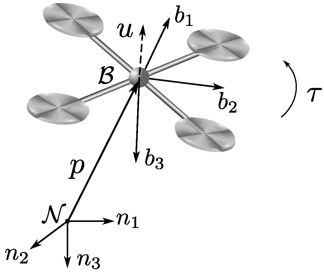
Figure 1. Quadrotor modeling notation.
Machines 13 00915 g001
Figure 2. The proposed UAM controller structure. The control of the UAV and that of the arm are decoupled.
Machines 13 00915 g002
Figure 3. UAM configuration.
Machines 13 00915 g003
Figure 4. Results for fixed-arm configuration ( α 1 = α 2 = 0 ). (a) Trajectories for p and ψ . (b) Tracking error. (c) Parameter estimates d ^ f and a ^ . (d) Parameter estimates d ^ τ . (e) Parameter estimates J ^ . (f) Inputs u and τ .
Machines 13 00915 g004
Figure 5. Results for the moving arm configuration. (a) Trajectories for p and ψ . (b) Tracking error. (c) Parameter estimates d ^ f and a ^ . (d) Parameter estimates d ^ τ . (e) Parameter estimates J ^ . (f) Inputs u and τ .
Machines 13 00915 g005
Figure 6. Fixed-arm configuration ( α 1 = α 2 = 0 ): (a) normalized tracking error norm e for fixed-parameter vs. adaptive case; (b) 2D top-view trajectories with desired path.
Machines 13 00915 g006
Figure 7. Moving-arm case: (a) normalized tracking error norm e for fixed-parameter vs. adaptive case; (b) 2D top-view trajectories with desired path.
Machines 13 00915 g007
Figure 8. Pick-and-place application results: (a) UAV pose and (b) position errors.
Machines 13 00915 g008
Table 1. UAV parameters.
ParameterValueParameterValue
m1.6 k g J x x , J y y 0.03 k g   m 2
J z z 0.05 k g   m 2 J x y , J z x , J y z 0.0 k g   m 2
Table 2. Arm parameters.
ParameterLink 1Link 2Link 3
Joint TypeRevoluteRevoluteFixed
Mass ( k g )0.10.10.1
Length ( m )0.20.30.1
Inertia ( k g   m 2 ) [ 7.508 , 7.533 , 0.0417 ] × 10 4 [ 7.508 , 7.533 , 0.0417 ] × 10 4 [ 1.667 , 1.667 , 1.667 ] × 10 4
Table 3. Control gains.
ParameterValueParameterValue
k 1 0.4 k 2 0.5
k 3 0.5 k 4 7
k d f 1 λ 3
Γ 0.001 k d τ 5
k ψ 1
Table 4. Settling time t s (s) and steady-state nRMSE (%) for the fixed-arm case.
Case t s (s)SS nRMSE (%)
Fixed parameters18.9333.34
Adaptive7.451.37
Table 5. Settling time t s (s) and steady-state nRMSE (%) for the moving-arm case.
Case t s (s)SS nRMSE (%)
Fixed parameters12.6033.57
Adaptive7.041.96
Table 6. Performance per case: settling time (5% criterion) and steady-state nRMSE (%) for fixed- and moving-arm configurations.
CaseFixed ArmMoving Arm
t s (s)SS nRMSE (%) t s (s)SS nRMSE (%)
17.391.736.772.64
27.251.806.802.42
37.931.267.811.56
47.552.207.282.38
57.631.527.332.07
67.391.516.891.92
77.331.476.842.04
87.641.577.432.18
97.541.647.442.12
107.161.546.832.05
STD0.250.260.290.29
Table 7. Object pick-and-place sequence.
Time tDesired Position p d Desired Yaw ψ d Arm ConfigurationCube Location
0 p d 1 ψ d 1 HomeTable 1
20 p d 1 ψ d 1 ExtendingTable 1
27 p d 1 + h ( t 27 ) ψ d 1 ExtendedTable 1
29 p d 1 + h ( t 27 ) ψ d 1 ExtendedUAM
32 p d 1 ψ d 1 RetractingUAM
40 p d 1 + p d 2 p d 1 1 + exp ( ( t 45 ) ) ψ d 2 1 + exp ( ( t 45 ) ) HomeUAM
60 p d 2 ψ d 2 ExtendingUAM
67 p d 2 + h ( t 67 ) ψ d 2 ExtendingUAM
70 p d 2 + h ( t 67 ) ψ d 2 ExtendedTable 2
73 p d 2 ψ d 2 RetractingTable 2
80 [ 0 , 0 , 0 ] T 0HomeTable 2
Disclaimer/Publisher’s Note: The statements, opinions and data contained in all publications are solely those of the individual author(s) and contributor(s) and not of MDPI and/or the editor(s). MDPI and/or the editor(s) disclaim responsibility for any injury to people or property resulting from any ideas, methods, instructions or products referred to in the content.