Abstract
Additive manufacturing (AM) has revolutionized the design and production of complex geometries by offering unprecedented creative freedom over traditional manufacturing. Despite its growing prominence, AM lacks automated and standardized design rules tailored to specific AM processes, resulting in time-consuming and expert-dependent manual verification. To address these limitations, this research introduces a novel design for additive manufacturing (DfAM) framework consisting of two complementary models designed to automate the design process. The first model, based on a decision tree algorithm, evaluates part compliance with established AM design rules. A modified J48 classifier was implemented to enhance data mining accuracy by achieving a 91.25% classification performance accuracy. This model systematically assesses whether input part characteristics meet AM processing standards, thereby providing a robust tool for verifying design rules. The second model features an AM design rule engine developed with a Python-based graphical user interface (GUI). This engine generates specific recommendations for design adjustments based on part characteristics and machine compatibility, offering a user-friendly approach for identifying potential design issues and ensuring DfAM compliance. By linking part specifications to various AM techniques, this model supports both researchers and engineers in anticipating and mitigating design flaws. Overall, this research establishes a foundation for a comprehensive DfAM expert system.
1. Introduction
Additive manufacturing (AM) involves the fabrication of intricate three-dimensional objects through a layer-by-layer technique with materials such as plastics, ceramics, or metals [1,2,3]. Traditional methods of manufacturing are limited in producing complex shapes and require extra steps, tools, and skilled labor, which raises the cost. In contrast, AM makes manufacturing complex geometries much easier with very few additional concerns [4,5]. Different types of AM processes include selective laser sintering (SLS) [6], fused deposition modelling (FDM) [7], stereolithography (SLA) [8], 3D printing (3DP) [9], and laminated object manufacturing (LOM) [10]. Expert systems, including artificial intelligence (AI)-based AM solutions, are employed in many domains, including process planning and work scheduling [11,12,13]. Three main factors impact an expert’s system job speed: (a) the geometrical complexity of parts, which in turn affects the yield of working space available around the part; (b) the total yield of the working space for this particular AM system; and (c) the technology used in the AM system [14,15].
AM processes have applications in various areas, including biomedical devices [16,17], semiconductor electronics [9], energy devices [18], and building and construction [19]. In each AM technology, there are distinct process capabilities, and the optimum use of material and machine resources requires expert assessment [20]. The large learning curve and specialized knowledge required for these technologies, however, do not allow for easy access to the AM technologies [21,22]. Biases of expert opinions and very limited off-the-shelf process guidelines add to the constraining factors against the spread of AM. Thereby, a generic system to assist novice designers and any AM enthusiast will serve as an important development toward its wider adoption in various applications [23,24].
Various research efforts have been made by both academia and industry to develop an expert AM-based system [25,26,27,28,29,30]. Kumke et al. illustrated a design concept framework to support design engineers during all phases of product development, enabling the full exploitation of potential from additive manufacturing and the development of AM-conformal designs [31]. Glen et al. investigated the additive manufacturing machine learning challenges by studying design repositories in a series of interconnected studies. A methodology demonstrated the study of the utility of large-scale engineering design repositories for additive manufacturing machine learning in both contexts: generalized and application-specific [32]. Stolt et al. showed how the integration of the AM design of components can be carried out with the design of the complete engine structure [33]. Wiberg et al. presented a DA (design automation) framework that smoothened the entire process of DfAM. It provides an overall view of the entire DfAM process by bringing on board all aspects concerning functional requirements to manufacturing evaluation and preparation within one design automation framework [34]. Pradel et al. proposed a DfAM framework that was based on a generic design process model made of five parts: conceptual design, embodiment design, detail design, process planning, and process selection [35]. Yao et al. introduced a hybrid machine learning algorithm for additive manufacturing design feature recommendation at a time during the phase of conceptual design [36]. Ghiasian et al. demonstrated an additive manufacturing recommender system for component inventories enabled by machine learning [37]. Ghazy et al. proposed an updatable decision support system, which supports a user’s choices of AM process chains, materials, finishing methods, and machines [38]. Yang et al. introduced an expert system for use in analyzing printability and integrability of assembly structure in design for additive manufacturing [39].
While previous efforts have been dedicated to automating the design and process planning stages of AM, there is still a need for a flexible framework that identifies AM process selections based on specific part requirements. In this research study, a data-driven system was developed for the optimum selection of AM processes based on CAD data and user-specified preferences. The AM techniques considered in this research include SLS, FDM, SLA, 3DP, and LOM. The specific objectives of the research included (a) generating a meta-model from an input part design to ensure conformity with the AM process rules and (b) developing a design for an AM rule engine, which gives recommendations on characteristics of the input part and compatibility with various machines.
2. Methodology
2.1. Design for Additive Manufacturing Framework (DFAM)
The design framework consists of four segments that include input (digital CAD design and extracting CAD features), database (AM process features thresholds and design rules guidelines, knowledge base, literature review, OEM database, and expert opinion), process analysis (decision tree algorithm and design rule engine), and output (DFAM rules compliance and rules recommendation). The overall framework of the research is illustrated in Figure 1.
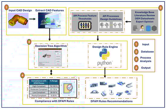
Figure 1.
DFAM Compliance and Design Rule Engine Framework.
2.2. Input CAD Feature Extraction
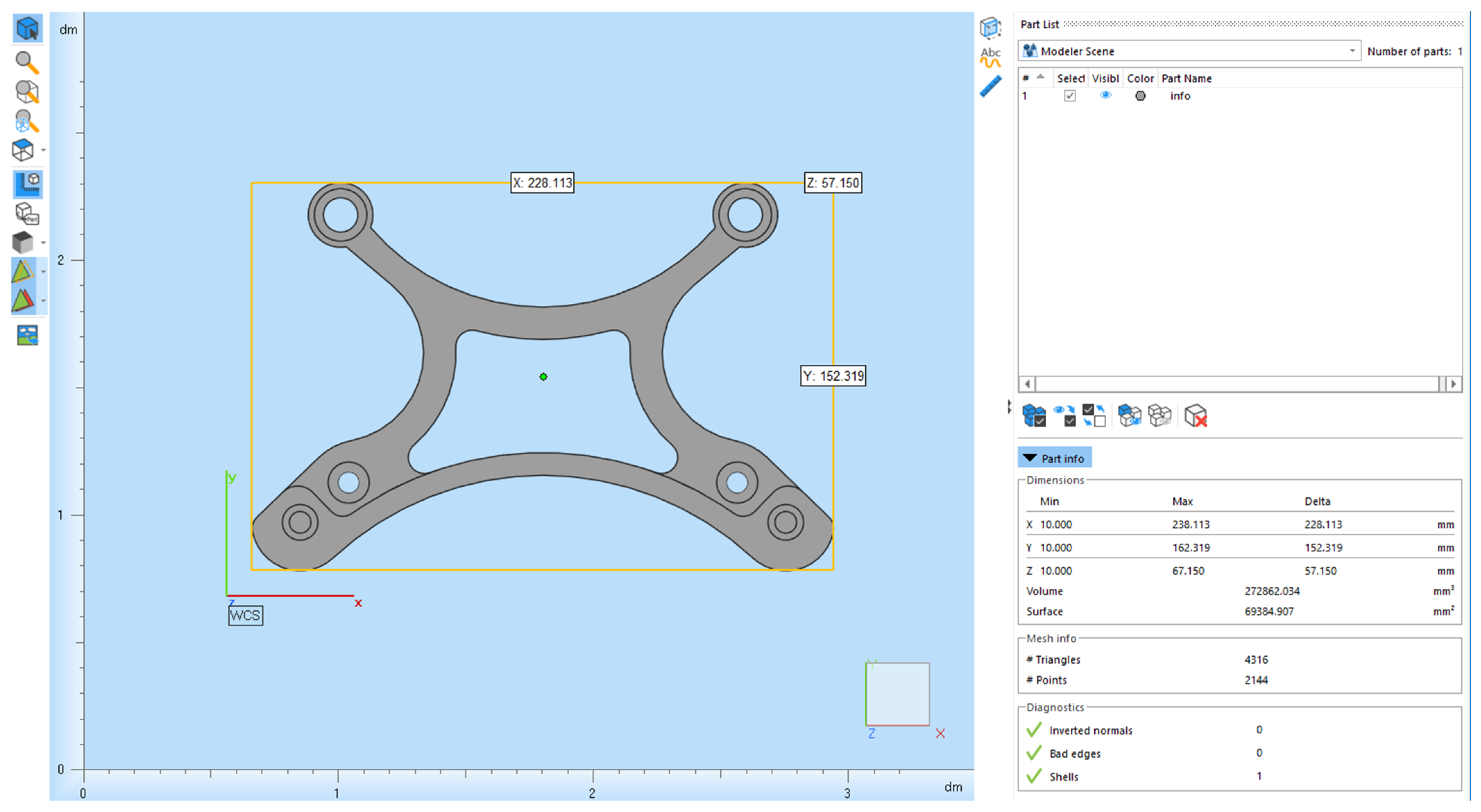
The digital computer-aided design (CAD) of the input part was exported as an STL file but can also be exported in STEP, IGES, OBJ, DWG, and DXF formats. The STL file was uploaded to the Magics software to extract crucial features such as minimum wall thickness, feature size, bosses/cylinders, hole size, minimum text size, tolerance, embosses, and engraved details, as shown in Figure 2.
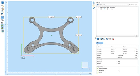
Figure 2.
CAD features were extracted using Magic’s 19.01 software.
Following the feature extraction, all gathered information was applied to a decision tree algorithm for evaluation. The decision tree requires a data sheet containing instances, where each instance is represented by features that describe the model to be 3D printed. The desired features—minimum wall thickness, hole size, embossed and engraved details, bosses/cylinders, minimum text size, feature size, and tolerances—were initially organized in a data file, with each row corresponding to a distinct part, as shown in Table 1. The AM techniques corresponding to respective 3D CAD parts are provided in Table 1 based on the DfAM framework established in this research study. Five AM techniques, which include SLS, FDM, SLA, 3DP, and LOM, were chosen for the evaluation. Each AM technique had 80 data instances derived from AM part sources [40]. Thus, our methodology can be applied to a variety of common input files used in the industry. Further, each type of input file can also be converted into STL format and vice versa, making it versatile in extracting the CAD features. In Figure 2, we demonstrate how an input part file can be used to extract dimensional information, which is then used to populate the datasheet shown in Table 1. The seven features, namely thickness, hole size, embossed details, bosses, text, feature size, and tolerance, are the most prominent features that are used in the literature to evaluate parts for different AM processes. Thus, our DfMA system provides a first-pass or first-stage methodology to seek if different parts can be manufactured with a variety of AM processes.

Table 1.
Sample CAD features data sheet for 400 parts.
2.3. Database
The DfAM database developed in this research involved compilation of information from different sources including datasheets from OEM and expert opinions [41,42,43]. Crucial for harnessing the full potential of AM are process feature thresholds and guidelines on design rules that enable an effective DfAM framework [44]. The thresholds define the minimum wall thickness, hole size, feature size, and levels of tolerance among other factors, as shown in Table 2 [45,46]. Knowledge of these thresholds enables designers to make decisions regarding the feasibility of designs [47,48]. Violation of one or more of these process feature thresholds for an input part resulted in different compliance values, as explained in Section 2.5.
Table 2.
Threshold values for different features in AM processes.
2.4. Process Analysis
Decision Tree Algorithm and Design Rule Engine: A model of the DfAM methodology consisted of four components, namely input part characteristics, database, process analysis, and output DfAM rules recommendations. This research work deals with efficient data mining procedures for predicting compliance with DFAM rules for an input part corresponding to each AM process [14]. The modified J-48 decision tree classifier algorithm was implemented [49,50,51] using the CAD features datasheet readable by the data mining tool WEKA [52,53]. By employing the meta model with data from both part characteristics and knowledge base, a program was developed using Python language to execute the design rule engine (Python) that develops DfAM rules recommendations [54]. The software requires only the part number as input; based on this, it searches for relevant constraints and provides appropriate DfMA (design for manufacturing and assembly) rule recommendations. After that, it performs the matching of input part number with relevant constraints available in the system and calculates the compliance percentage. In addition to compliance, the system finds both compliant and non-compliant design rules and generates recommendations. The number of recommendations is linked to accepted design rules, with an alert mechanism for instances falling below a minimum threshold.
2.5. Output
2.5.1. Compliance with DFAM Rules
Table 3 shows the compliance with DfAM rules ranging from 0 to 100%. This table serves as the key concept in determining the compliance of the CAD design features dataset with respective AM processes.
Table 3.
An expert judgment for compliance with DFAM rules.
2.5.2. Design Rules Recommendations
Table 4 shows design rules recommendations for the FDM technique. Further, Appendix A, Appendix B, Appendix C and Appendix D show the design rules for other AM processes that were used in this research. All information was gathered from a literature review, operation equipment manufacturing (OEM), and expert opinion.
Table 4.
Design Rules Recommendations for FDM.
3. Results and Discussion
The feasibility of the proposed DfAM framework was demonstrated in two stages. Stage 1 involved evaluating compliance with AM rules, and Stage 2 involved developing AM design rules recommendations.
3.1. Stage 1: Evaluating Compliance with AM Rules
In this stage, multiple case studies with different dataset sizes of 100, 200, and 400 were evaluated. The training to the test dataset was in a 80:20 ratio for all the above datasets. Thus, for the 400 dataset, there were 320 sample (parts) for training and 80 for the test dataset, respectively. The CAD model datasets were analyzed by the J-48 decision tree classification algorithm. The classification model was used to evaluate expert judgment classifying compliance with DfAM rules into four categories: highly, moderately, lowly, and poorly compliant [18]. In the table, design rules for compliance are highlighted with green and non-compliance with red. Compliance percentage was calculated based on Equation (1). Table 4 shows the minimum constraint values or threshold for each feature with respect to the FDM process. Thus, an actual CAD feature of the AM processes should be greater or equal to be acceptable or compliant for each feature [19]. Table 5 illustrates the sample datasets for AM process compliance of different CAD models.
Table 5.
Sample datasets for AM process compliance of different CAD models.
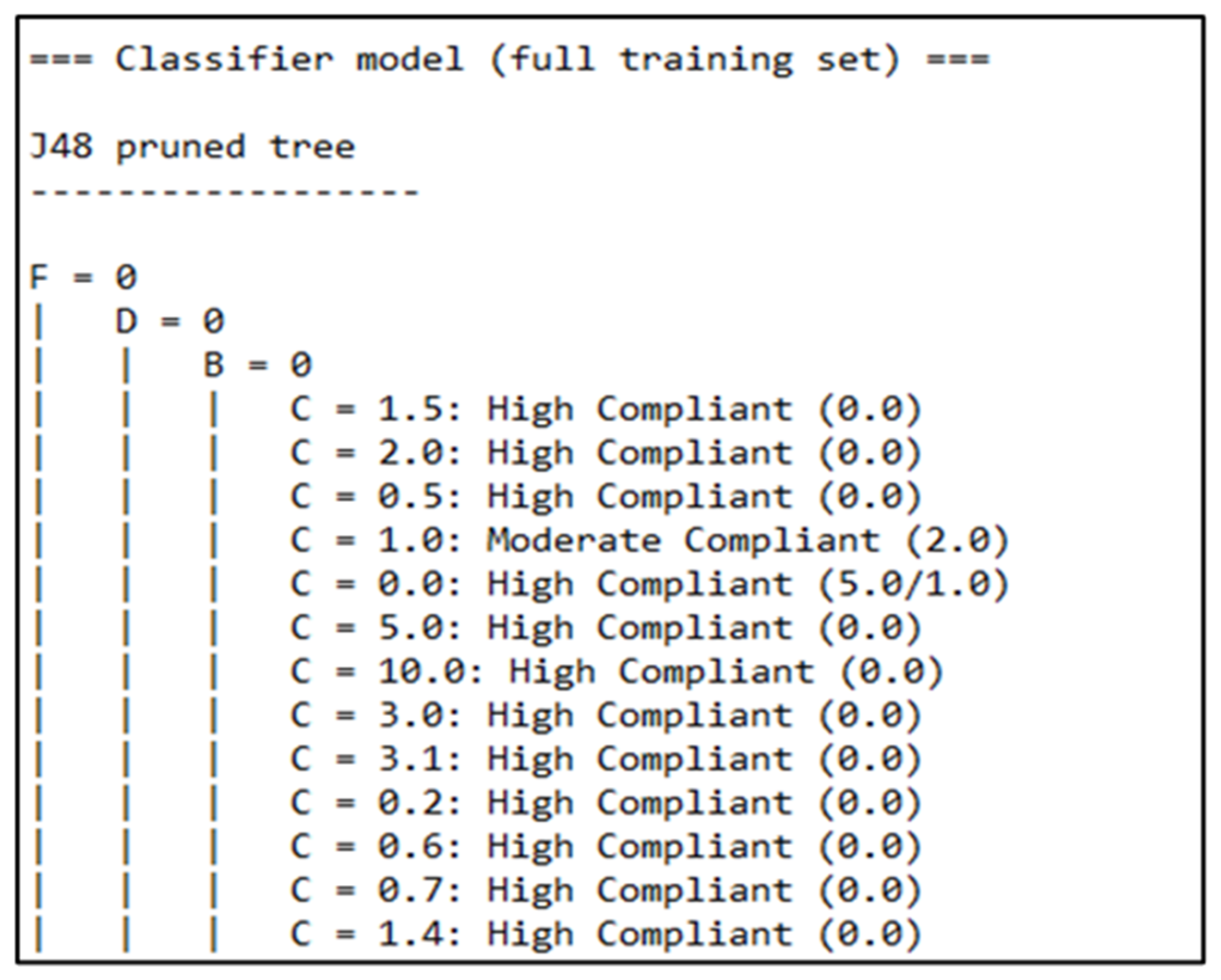
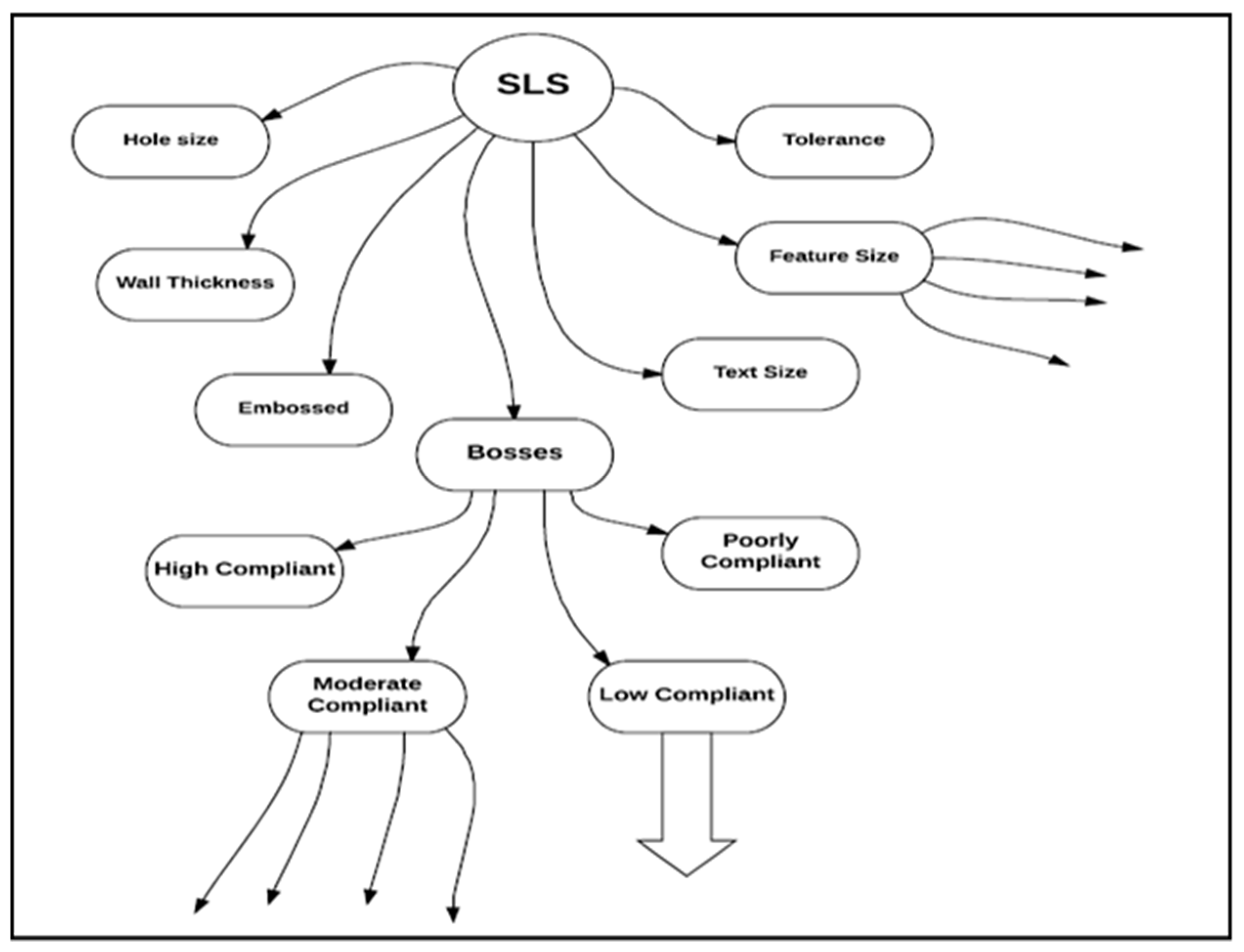
Figure 3 illustrates the J-48 pruned tree classifier model as a full training test. Pruning reduces the complexity of the final classifier and hence improves predictive accuracy by the reduction of overfitting [55]. The main objective of this algorithm was to achieve perfect classification with a minimal number of decisions. In this research, the CAD dataset features of various AM processes such as SLS, FDM, 3DP, LOM, and SLA were investigated to determine compliance with AM design rules. In Figure 4, tree-based modeling is carried out with selective laser sintering (SLS) techniques in a classification framework. That framework depicts a multi-level decision tree with attributes and internal nodes, with the terminal nodes indicating predicted outcomes. This J-48 algorithm uses the information gain approach to obtain the best split. It returns information gained as the difference between the entropy before and after splitting. Entropy here is a measure for the impurity or uncertainty of information [56]. Equation (2) represents the formula of entropy.
wherein pP is the proportion of positive (training) examples, and pN is the proportion of negative (training) examples.
Entropy = −pP × log2 (pP) − pN × log2 (pN)
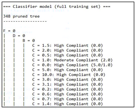
Figure 3.
Sample of J48 pruned tree.
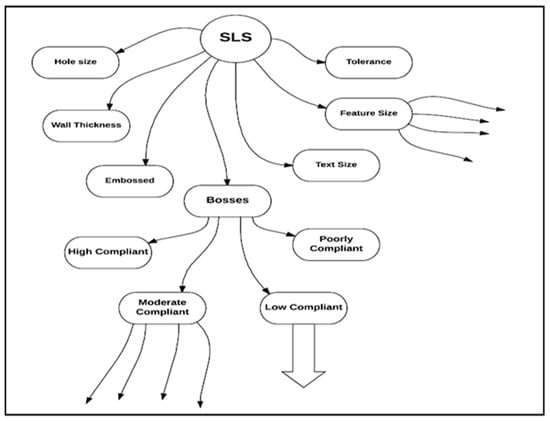
Figure 4.
Decision tree classification of SLS technique with attributes.
Case Study Results for 100, 200, and 400 Datasets
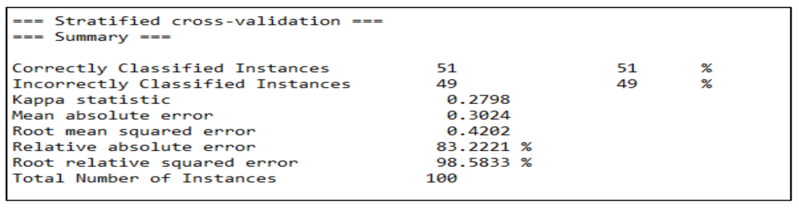
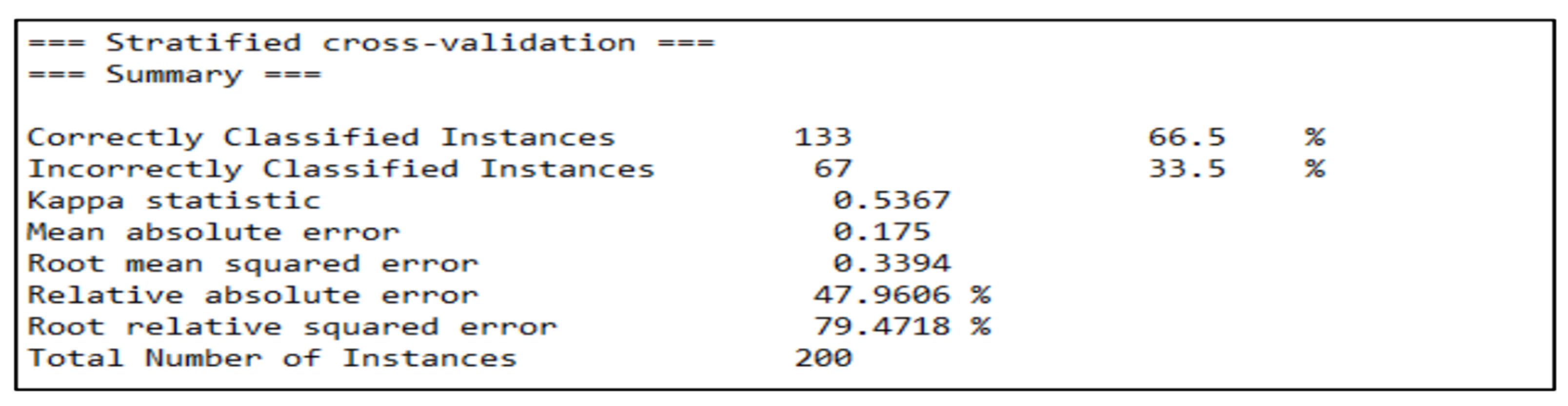
Initially, the training and testing datasets were imported into the WEKA software 4.2 to analyze the different types of datasets, such as 100, 200, and 400. The output accuracy for datasets 100 and 200 is presented in Figure 5 and Figure 6, respectively. The output accuracy for the 100 dataset was 51%, as shown in Figure 5. The output accuracy for the 200 dataset was around 66.5%, as shown in Figure 6, which is a significant improvement over the dataset with 100. The kappa statistic increased from 100 instances, and the error rates decreased. Each of the test instances was classified based on its respective eligible techniques, such as SLS, FDM, SLA, LOM, and 3DP. The lower right section of Figure 7 shows the count of expert judgment’s classification for each of the five AM processes.
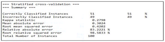
Figure 5.
Stratified cross-validation for 100 dataset.
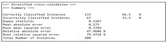
Figure 6.
Stratified cross-validation for 200 dataset.
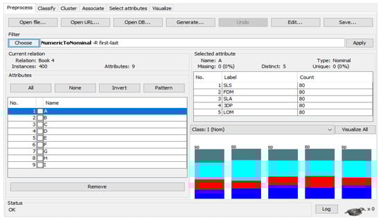
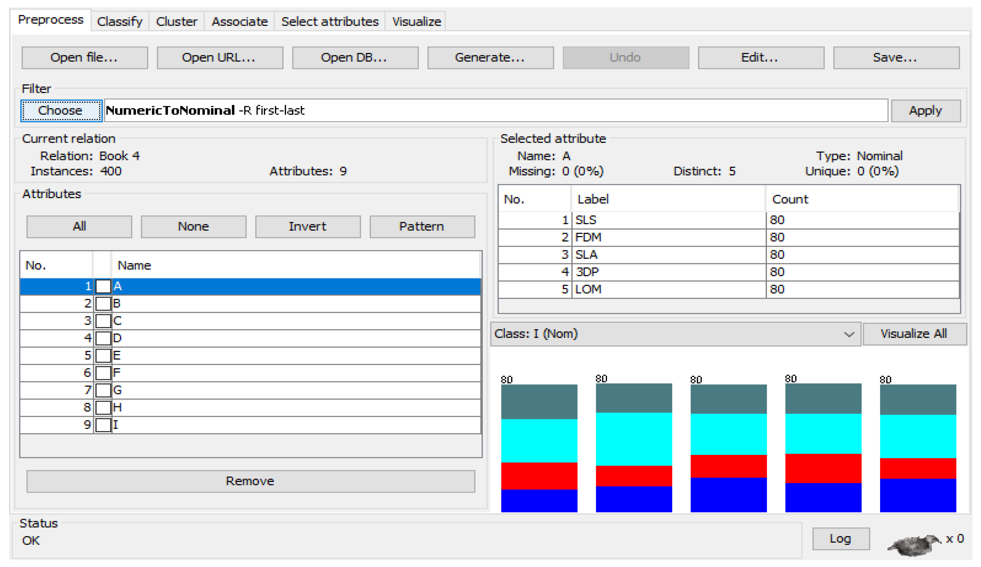
Figure 7.
Applying data sheets to WEKA for 400 dataset.
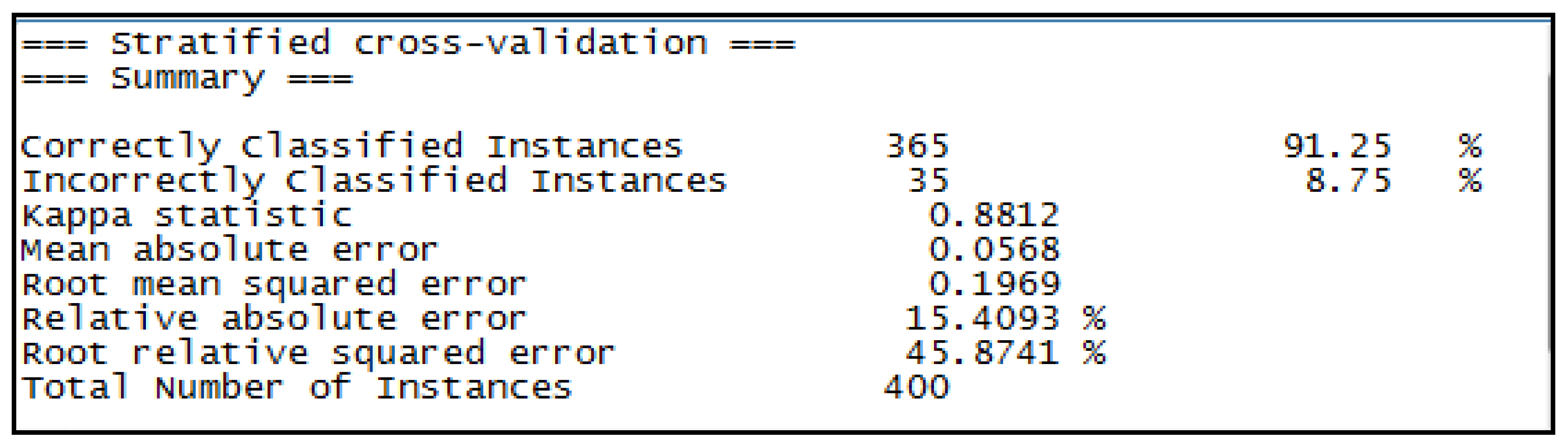
Figure 7 illustrates the WEKA terminal with the 400 dataset for different AM techniques. SLS, the first bar, has an almost perfect distribution of the classification, with bluish green showing high compliance, sky blue showing moderate compliance, red showing poor compliance, and blue showing low compliance. FDM is falls majorly under moderate compliance, SLA shows fairly perfect distribution, 3DP is majorly classified as moderately compliant, and LOM similarly shows a majority of the instances being moderately compliant. With the 400 instance dataset, as shown in Figure 7, all the techniques had a fair spread of expert judgments. This was executed on WEKA, and the output accuracy was 91.25%, as shown in Figure 8.
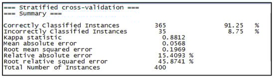
Figure 8.
Stratified cross-validation for 400 dataset.
From Table 6, it can be illustrated that class-specific accuracy resulted in the highest ROC area of 0.972. The “Highly compliant” class had both the highest true-positive and false-positive rates, but the latter was contained within only 5%. The results indicate that further increasing the size of the train dataset and balancing the expert opinions about techniques make a real difference in additive manufacturing rules classification. In these methods, with statistical measures such as kappa statistics, error rates improved with the increase in the number of instances. The pruned tree created by the J-48 algorithm marked some important features decisive for any job compliance to actually be 3D-printed.
Table 6.
Details of accuracy by class for 400 datasets.
3.2. Stage 2: Developing AM Design Rules Recommendations
In this stage, the AM design rules were developed based on the range of compliance results. As mentioned earlier, a sample of 200 parts was considered, and the part quantity can be further extended based on the user requirements. To demonstrate the feasibility of the design engine rules, a case study on parts numbers 1, 50, and 80 was investigated.
3.2.1. Case Study for Part Number 80
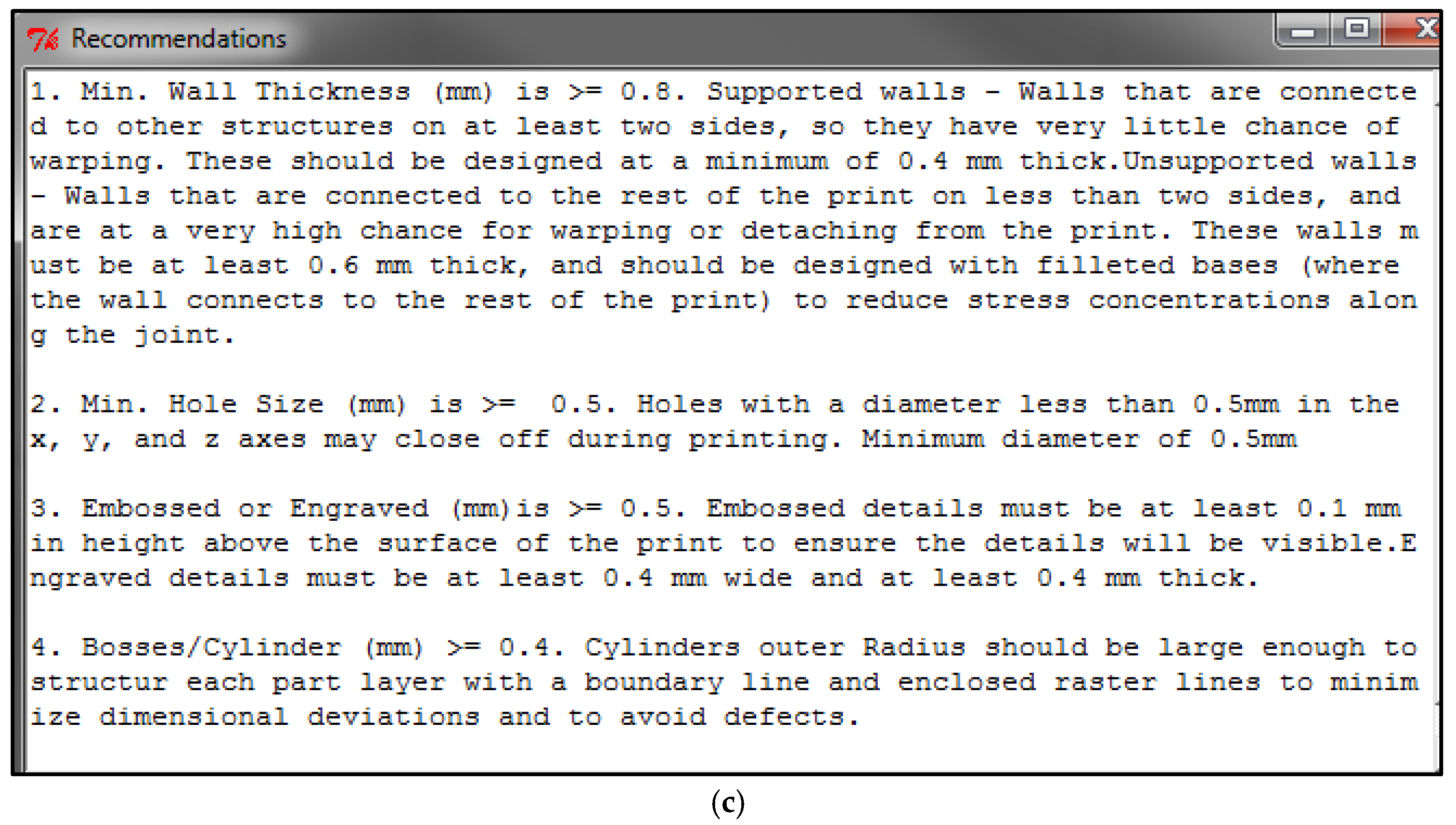
Part number 80 was evaluated in the context of the DfAM rules recommendation framework. This part was related to the FDM AM technique. Based on the J48 classifier decision tree algorithm, the part compliance design rules were satisfied with a range of 75% only. Of the seven design features used, only four of them were considered for this part, and for one feature, the bosses did not meet the recommended minimum threshold constraint values for the features. Table 7 illustrates the datasheet for part number 80, the column: bosses were colored red if they missed the minimum threshold requirements. The design rule engine thus suggests recommendations for part number 80 on the bosses/cylinder feature. Figure 9a illustrates the CAD design of the part. Figure 9b shows the design rule engine window for part number 80. Finally, a new window containing recommended recommendations will open by clicking on the recommendations option in the design engine window, as shown in Figure 9c.
Table 7.
Datasheet for part number 80.
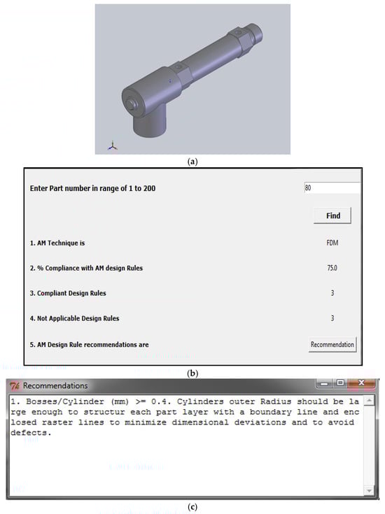
Figure 9.
(a) CAD design of part number 80 from Magic’s software. (b) Design rule engine for part number 80. (c) Recommendations for part number 80.
3.2.2. Case Study for Part Number 1
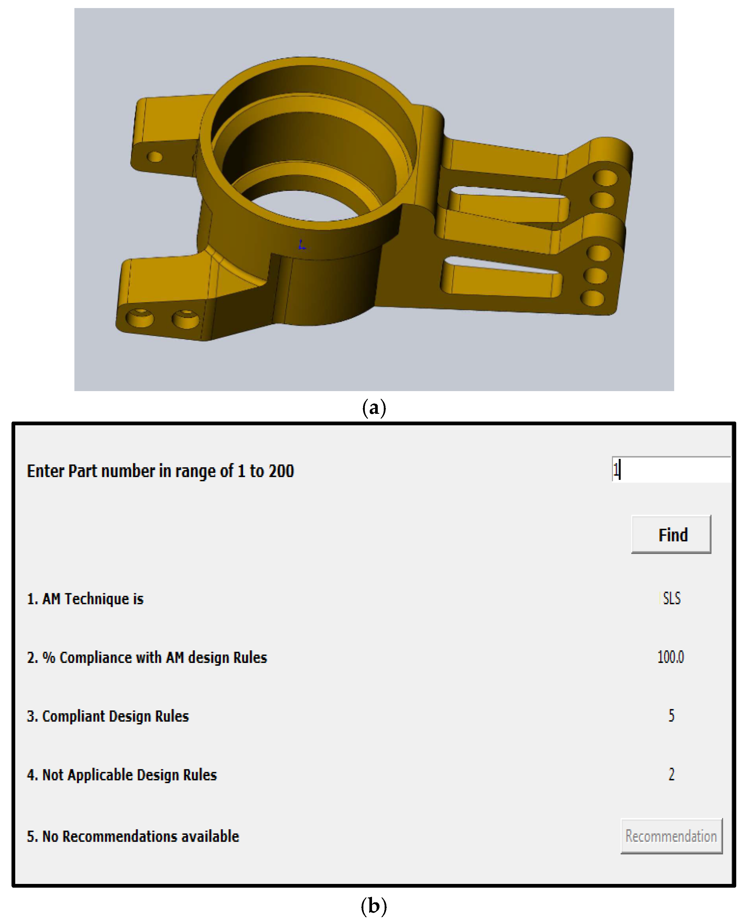
Part number 1 was evaluated by using the DfAM framework. Figure 10a represents the CAD design of the part and was related to the SLS technique. The J48 classifier decision tree algorithm suggested that all the compliance design rules were satisfied within the 100% range. Table 8 illustrates the datasheet for part number 1. Out of all the seven design features considered, only five of them applied to this part, and all those design rules met the recommended features’ minimum threshold constraint values. Thus, no recommendations were suggested by the design rule engine for part number 1. Figure 10b illustrates the design rule engine window for part number 1.

Figure 10.
(a) CAD design of part number 80 from Magic’s software. (b) Design rule engine for part number 1.
Table 8.
Datasheet for Part number 1.
3.2.3. Case Study for Part Number 50
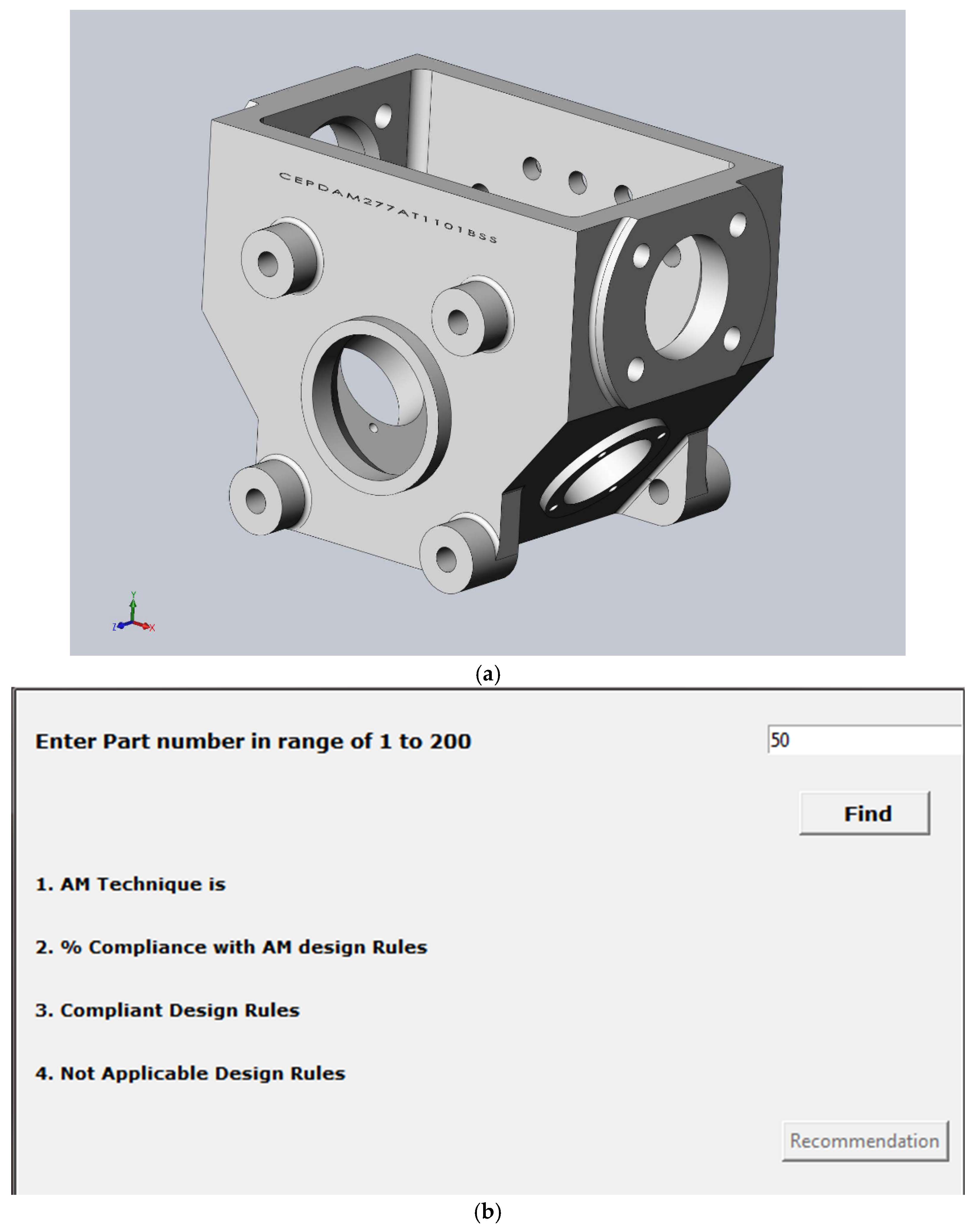
Part number 50, as shown in Figure 11a, was evaluated by using the DfAM framework as the SLS part. The J48 classifier decision tree algorithm analysis suggested that the design rules were poorly compliant, with less than a 25% range. Table 9 illustrates the datasheet for part number 50. Out of all the seven design features considered, four of them did not meet the recommended feature minimum threshold constraint values. Figure 11b illustrates the design rule engine window for part number 50. The findings represent that part number 50 results in multiple recommendations, as shown in Figure 11c, because the design rules did not meet the minimum threshold requirements of this object.
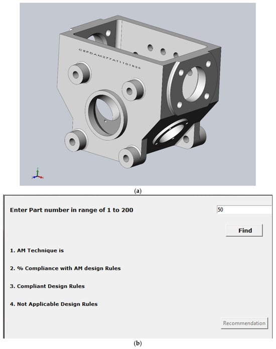
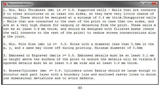
Figure 11.
(a) CAD design of part number 50. (b) Start page for design rule engine for part number 50. (c) Recommendations page for part number 50.
Table 9.
Datasheet for part number 50.
4. Discussion, Limitations, and Future Work
4.1. Discussion
The design for additive manufacturing (DfAM) framework engine developed in this research offers valuable utility to AM researchers and the industry, which relies on compliance with the rules of AM and a design rule engine. In the case of AM researchers, the DfAM framework engine acts as a meta-model in assessing compliance with AM processing rules. In this work, it is demonstrated that the framework diagnosed compliance with DfAM design rules for new datasets containing a total of 400 instances to give an appreciable classification accuracy of 91.25% using the tJ-48 decision tree of the WEKA data mining suite. This further enhances the engine capacity to scale up the training dataset to size, increases coverage of balanced expert judgments, and gives greatly improved classification results and hence useful insight and actionability for the researchers working on AM design [45]. The next best evidence of the effectiveness that the DfAM framework engine has to offer is in its ability to preempt or mitigate design problems in the paradigm [24,46]. The part numbers are mapped to the different additive manufacturing processes, and their associated constraints are retrieved while compliance is calculated, and the design rules are created. This feature allows spotting potential errors at the initial steps of the design process and thus helps to avoid costly iterations. The DfAM rule engine was developed in Python, which can be integrated easily into any existing workflow, and hence, its use by industry professionals will be easy and accessible [47]. The desired features considered in this research, which include minimum wall thickness, hole size, embossed and engraved details, bosses/cylinders, minimum text size, feature size, and tolerances, are the initial fundamental features for any AM process. These above-mentioned features of a 3D CAD design have a significant impact on the manufacturability, functionality, structural integrity, and postprocessing of the AM fabricated objects with respective AM techniques [23,24]. These features address the distinctive challenges of the respective AM processes, such as material behavior, geometric resolution limits, thermal effects, and postprocessing requirements. By precisely taking these features into consideration throughout the design phase, AM engineers can maximize the full potential of the producibility, cost efficiency, and performance of AM 3D components [25].
4.2. Limitations
Regardless of the developments in AM, there exist various shortcomings in design optimization. The current design guidelines, which include minimum wall thickness, hole size, embossed and engraved details, bosses/cylinders, minimum text size, feature size, and tolerances, are basic first-pass features. Despite the technological advancements in additive manufacturing, various limitations persist in terms of design optimization. Current design guidelines, including wall thickness, hole sizes, and tolerances, are often limited to specific materials or equipment corresponding to a respective AM process, which limits their general use [47,48]. To overcome such challenges, standardized, predictive, and sustainable design paradigms matched to the increasing capabilities of AM need to be established for broader adoption of the AM processes across different fields.
4.3. Future Work
Additive manufacturing design principles are evolving with new challenges and opportunities. Development of data-driven criteria for optimization of parameters such as build orientation, wall thickness and hole diameter, material, and the additive manufacturing process should be investigated to maximize the future prospects of AM processes’ manufacturability to full capability. Research on controlling material transition and optimization of tolerances in multi-material printing needs to be undertaken. Since the resulting parts can suffer from shrinkage and thermal stresses, enhanced dimensional accuracy is a requirement, which may improve using predictive models [24]. Design details such as text clarity need better geometrical designs or advanced layering techniques. AM tolerance practices need refinement for anisotropic properties and postprocessing. Standards should be established for new technologies, including hybrid AM, high-speed sintering, and minimum wall thickness. Integrated automatic tools and additive manufacturing constraints can aid in ensuring AM process manufacturability with maximized strength and functionality. This includes tools for analyzing lattice structures and providing guidance using topological optimization. Standardization of the additive manufacturing platforms will provide consistency in quality and ensure the full potential of the AM process for wide range of applications [46].
Future works can involve integrating machine learning algorithms within the design rule engine to enhance its capabilities and evolve the prediction-grade decision-support features of the DfAM framework. Future work may further populate the knowledge base through real-time data in the various AM processes and include feedback mechanisms to serve in further improving the adaptability and robustness of the design rule engine [57,58,59]. Through a more interactive user interface and making the engine compatible with different AM software, applicability and adoption could increase through the entire AM industry.
5. Conclusions
A design for additive manufacturing (DfAM) framework was developed in this research for various AM techniques by establishing compliance using decision tree algorithm and design rule engine recommendations. Crucial features such as minimum wall thickness, feature size, bosses/cylinders, hole size, minimum text size, tolerance, embosses, and engraved details were considered as baseline features to evaluate input parts for AM process compatibility. Threshold values for the above features were compiled using sources from the literature for five prominent AM processes commonly used in practice. These include SLS, FDM, SLA, 3D printing, and LOM. The compliance of the 3D parts was predicted by implementing the J-48 decision tree classification algorithm for multiple case studies with dataset sizes such as 100, 200, and 400 parts. The findings of the study demonstrated that the output accuracy of the 100 dataset and 200 dataset was 51% and 66.5%, respectively. This clearly indicates that data augmentation is vital for higher accuracies. Thus, an accuracy of 91.25% was achieved for AM compliance for a dataset of 400 parts. Moreover, the feasibility of the design rule engine developed by python graphical user interface was investigated by conducting case analysis on various 3D CAD parts designs. The Python-based engine enabled the early detection of potential errors that may be committed in the AM 3D design process, which is very promising for AM researchers and engineers to avert and minimize design errors. Three case studies were illustrated for distinct parts with 25%, 75%, and 100% compliance, along with their subsequent design modification recommendations. The results of the study illustrate the superiority of the DfAM framework not only in terms of providing accurate predictions of AM 3D CAD parts compliance but also demonstrating the recommended design rules for respective 3D CAD parts to maintain the AM design guidelines. The baseline feature considered in this research plays a significant role in evaluating the compatibility of a 3D CAD parts’ manufacturability with the five prominent AM processes, thus enabling the advancement of DfAM expert system development for the AM industry.
Author Contributions
All authors contributed to the study conception and design. Material preparation, data collection, and analysis were performed by B.A.A., S.K.P., and S.D.; the first draft of the manuscript was written by S.K.P. and S.D. All authors have read and agreed to the published version of the manuscript.
Funding
This research was funded by the National Science Foundation. The authors extend their gratitude to the U.S. National Science Foundation (NSF Awards #2434487, #2100739, #2100850, #2200538, 2315654) for support towards this research.
Data Availability Statement
The data presented in this study are available on request from the corresponding author.
Conflicts of Interest
The authors declare no conflicts of interest. The funders had no role in the design of the study; in the collection, analysis, or interpretation of data; in the writing of the manuscript; or in the decision to publish the results.
Appendix A. Design Rules Recommendations for SLA
| Features | Threshold Value (mm) | Recommendations |
| Min. Thickness (mm) | ≥0.8 | Supported walls: These walls have extremely low likelihood of warping because they are attached to other structures on at least two sides. These must have a minimum thickness of 0.4 mm. Unsupported walls: These walls have a very high risk of warping or separating from the print because they are only attached to two sides of the print. To lessen stress concentrations around the joint, these walls—where the wall joins the remainder of the print—should have filleted bases and be at least 0.6 mm thick. |
| Min. Hole Size (mm) | ≥0.5 | During printing, holes in the x, y, and z axes that have a diameter smaller than 0.5 mm may seal off. A minimum of 0.5 mm in diameter is necessary. |
| Embossed or Engraved (mm) | ≥0.5 | In order ensure visibility, embossed details must be at least 0.1 mm above the print’s surface. Details that are engraved must be at least 0.4 mm thick and 0.4 mm wide. |
| Bosses/Cylinder (mm) Like SLS | ≥0.4 | Cylinders’ outer radius should be large enough to structure each part layer with a boundary line and enclosed raster lines to minimize dimensional deviations and to avoid defects. |
| Min. Text Size (mm) | ≥1 | Recommended raised text to be at least 0.013” (0.3302 mm) tall or recessed. |
| Min Feature Size | ≥0.5 | The laser spot size must always be greater than the minimum feature size. Very tiny details, with a minimum feature size of 0.2 mm, are retained by this resin. Resin burns out with little to no trace or ash when it is properly cured. |
| Tolerance (mm) | ≥0.2 | SLA prototypes can achieve tolerances +/−0.005” (0.127 mm) for the initial inch, plus an additional 0.002” (0.0508 mm) for each additional inch. |
Appendix B. Design Rules Recommendations for SLS
| Features | Threshold Value (mm) | Recommendations |
| Min. Thickness (mm) | ≥0.7 | The wall thickness should be large enough to structure each part layer with a boundary line and enclosed raster lines to minimize dimensional deviations and to avoid defects. |
| Min. Hole Size (mm) | ≥0.8 | If hole curvatures are mainly approximated by layers, a cylinder’s inner radius should be as large as possible in order to decrease the approximation error related to the nominal inner radius. |
| Embossed or Engraved (mm) | ≥0.8 | The guidelines below are applicable to make sure little details are visible: Engraving must be at least 1 mm deep and embossed at least 1 mm high. |
| Bosses/Cylinder (mm) Like SLS | ≥0.8 | Cylinders outer radius should be large enough to structure each part layer with a boundary line and enclosed raster lines to minimize dimensional deviations and to avoid defects. |
| Min. Text Size (mm) | ≥2 | The following guidelines are applicable to guarantee text readability: For all directions, a minimum font height of 2 mm (font size 14) is appropriate. For readability, a sans serif typeface is advised. |
| Min Feature Size | ≥0.5 | 0.8 mm is the minimal size that is advised. Practically speaking, LS features must be at least 0.030 inches (0.8 mm) in size. |
| Tolerance (mm) | ≥0.3 | For SLS parts, the usual tolerances are either ± 0.05 mm/mm or ± 0.3 mm, whichever is larger. |
Appendix C. Design Rules Recommendations for 3DP
| Features | Threshold Value (mm) | Recommendations |
| Min. Thickness (mm) | ≥1.2 | Major supported walls: Major supported walls must have a minimum wall thickness of 1 mm. Every other wall: The minimum wall thickness for every other wall shall be at least 0.5 mm. |
| Min. Hole Size (mm) | ≥0.5 | For a hole to print properly, its minimum diameter must be at least 0.5 mm. Whenever feasible, holes should be positioned vertically to increase the feature’s circularity. |
| Embossed or Engraved (mm) | ≥0.5 | The following guidelines are applicable to make sure minor details are visible: 0.5 mm is the minimum engraving depth, and 0.5 mm is the minimum embossing height. |
| Bosses/Cylinder (mm) Like SLS | ≥0.5 | Cylinders outer radius should be large enough to structure each part layer with a boundary line and enclosed raster lines to minimize dimensional deviations and to avoid defects. |
| Min. Text Size (mm) | ≥1.5 | At least 0.8 mm of details must be present in your model in order to produce visible details with general-purpose plastics. |
| Min Feature Size | ≥0.5 | With material jetting, part details as small as 0.25 mm can be produced. |
| Tolerance (mm) | ≥0.1 | Parts manufactured via material jetting have tolerances ranging from +/−0.1 mm to −0.3 mm, depending on the material and geometry. |
Appendix D. Design Rules Recommendations for LOM
| Features | Threshold Value (mm) | Recommendations |
| Min. Thickness (mm) | ≥1.8 | The wall thickness should be large enough to structure each part layer with a boundary line and enclosed raster lines to minimize dimensional deviations and to avoid defects. |
| Min. Hole Size (mm) | ≥2.0 | If hole curvatures are mainly approximated by layers, a cylinder’s inner radius should be as large as possible in order to decrease the approximation error related to the nominal inner radius. |
| Embossed or Engraved (mm) | ≥2.0 | In order to make minor details noticeable, the following guidelines are applicable: 2 mm is the minimum engraving depth, and 2 mm is the minimum embossing height |
| Bosses/Cylinder (mm) Like SLS | ≥2.0 | Cylinders outer radius should be large enough to structure each part layer with a boundary line and enclosed raster lines to minimize dimensional deviations and to avoid defects. |
| Min. Text size (mm) | ≥1 | A greater heat-affected zone is produced when the laser engraving tool interacts with paper or plastic materials. Therefore, 3 mm and larger is the smallest text size that can be engraved. |
| Min Feature Size | ≥1.2 | LOM primarily uses paper or polymer sheets, which limits accuracy of features. Typical accuracy of features ranges from 1.2 to 2.0 mm. |
| Tolerance (mm) | ≥0.8 | Recommended tolerance of +/−1 mm. |
References
- Gibson, I.; Rosen, D.; Stucker, B. Additive Manufacturing Technologies 3D Printing, Rapid Prototyping, Direct Digital Manufacturing; Springer: Berlin/Heidelberg, Germany, 2012. [Google Scholar]
- Wohlers, T.; Caffrey, T. Additive manufacturing: Going mainstream. Manuf. Eng. 2013, 150, 67–73. [Google Scholar]
- Scott, J.; Gupta, N.; Weber, C.; Newsome, S.; Wohlers, T.; Caffrey, T. Additive Manufacturing: Status and Opportunities; Institute of Defense Analyses (IDA): Alexandria, VA, USA, 1998; pp. 935–940. [Google Scholar]
- Jandyal, A.; Chaturvedi, I.; Wazir, I.; Raina, A.; Haq, M.I.U. 3D printing—A review of processes, materials and applications in industry 4.0. Sustain. Oper. Comput. 2022, 3, 33–42. [Google Scholar] [CrossRef]
- Parupelli, S.; Desai, S. A comprehensive review of additive manufacturing (3D printing): Processes, applications and future potential. Am. J. Appl. Sci. 2019, 16, 244–272. [Google Scholar] [CrossRef]
- Kumar, M.B.; Sathiya, P.; Varatharajulu, M. Selective laser sintering. In Advances in Additive Manufacturing Processes; China Bentham Books: Beijing, China, 2021; p. 28. [Google Scholar]
- Vyavahare, S.; Teraiya, S.; Panghal, D.; Kumar, S. Fused deposition modelling: A review. Rapid Prototyp. J. 2019, 26, 176–201. [Google Scholar] [CrossRef]
- Huang, J.; Qin, Q.; Wang, J. A review of stereolithography: Processes and systems. Processes 2020, 8, 1138. [Google Scholar] [CrossRef]
- Murr, L.E. 3D Printing: Printed Electronics. In Handbook of Materials Structures, Properties, Processing and Performance; Springer: Cham, Switzerland, 2015; pp. 613–628. [Google Scholar]
- Feygin, M.; Freeform, B.H. Laminated object manufacturing (LOM): A simpler process. In Proceedings of the 1991 International Solid Freeform Fabrication Symposium, Austin, TX, USA, 12–14 August 1991; Available online: http://hdl.handle.net/2152/64325 (accessed on 12 September 2024).
- Air, A.; Wodehouse, A. A DfAM framework for the design of compliant structures. Proc. Des. Soc. 2023, 3, 111–120. [Google Scholar] [CrossRef]
- Thompson, M.K.; Moroni, G.; Vaneker, T.; Fadel, G.; Campbell, R.I.; Gibson, I.; Bernard, A.; Schulz, J.; Graf, P.; Ahuja, B.; et al. Design for Additive Manufacturing: Trends, opportunities, considerations, and constraints. CIRP Ann. 2016, 65, 737–760. [Google Scholar] [CrossRef]
- Rosen, D. Design for additive manufacturing: Past, present, and future directions. J. Mech. Des. 2014, 136, 090301. [Google Scholar] [CrossRef]
- Brajlih, T.; Valentan, B.; Balic, J.; Drstvensek, I. Speed and accuracy evaluation of additive manufacturing machines. Rapid Prototyp. J. 2011, 17, 64–75. [Google Scholar] [CrossRef]
- Hague, R.; Campbell, I.; Dickens, P. Implications on design of rapid manufacturing. Proc. Inst. Mech. Eng. C J. Mech. Eng. Sci. 2003, 217, 25–30. [Google Scholar] [CrossRef]
- Curodeau, A.; Sachs, E.; Caldarise, S. Design and fabrication of cast orthopedic implants with freeform surface textures from 3-D printed ceramic shell. J. Biomed. Mater. Res. Off. J. Soc. Biomater. Jpn. Soc. Biomater. Aust. Soc. Biomater. Korean Soc. Biomater. 2000, 53, 525–535. [Google Scholar] [CrossRef]
- Ogunsanya, M.; Desai, S. Physics-based and data-driven modeling for biomanufacturing 4.0. Manuf. Lett. 2023, 36, 91–95. [Google Scholar] [CrossRef]
- Sun, K.; Wei, T.; Ahn, B.Y.; Seo, J.Y.; Dillon, S.J.; Lewis, J.A. 3D printing of interdigitated Li-Ion microbattery architectures. Adv. Mater. 2013, 25, 4539–4543. [Google Scholar] [CrossRef] [PubMed]
- Rayna, T.; Striukova, L. The impact of 3D printing technologies on business model innovation. In Digital Enterprise Design & Management: Proceedings of the Second International Conference on Digital Enterprise Design and Management DED&M 2014, Paris, France, 4–5 February 2014; Springer: Berlin/Heidelberg, Germany, 2014; pp. 119–132. [Google Scholar]
- Olowe, M.; Ogunsanya, M.; Best, B.; Hanif, Y.; Bajaj, S.; Vakkalagadda, V.; Fatoki, O.; Desai, S. Spectral Features Analysis for Print Quality Prediction in Additive Manufacturing: An Acoustics-Based Approach. Sensors 2024, 24, 4864. [Google Scholar] [CrossRef]
- Aljabali, B.A.; Shelton, J.; Desai, S. Genetic Algorithm-Based Data-Driven Process Selection System for Additive Manufacturing in Industry 4.0. Materials 2024, 17, 4544. [Google Scholar] [CrossRef]
- Ogunsanya, M.; Isichei, J.; Desai, S. Grid search hyperparameter tuning in additive manufacturing processes. Manuf. Lett. 2023, 35, 1031–1042. [Google Scholar] [CrossRef]
- Gibson, I.; Rosen, D.; Stucker, B.; Khorasani, M.; Gibson, I.; Rosen, D.; Stucker, B.; Khorasani, M. Design for additive manufacturing. In Additive Manufacturing Technologies; Springer: Berlin/Heidelberg, Germany, 2021; pp. 555–607. [Google Scholar]
- Diegel, O.; Nordin, A.; Motte, D. A Practical Guide to Design for Additive Manufacturing; Springer: Berlin/Heidelberg, Germany, 2020. [Google Scholar]
- Obi, M.U.; Pradel, P.; Sinclair, M.; Bibb, R. A bibliometric analysis of research in design for additive manufacturing. Rapid Prototyp. J. 2022, 28, 967–987. [Google Scholar] [CrossRef]
- Desai, S.; Bidanda, B.; Lovell, M.R. Material and process selection in product design using decision-making technique (AHP). Eur. J. Ind. Eng. 2012, 6, 322–346. [Google Scholar] [CrossRef]
- Elhoone, H.; Zhang, T.; Anwar, M.; Desai, S. Cyber-based design for additive manufacturing using artificial neural networks for Industry 4.0. Int. J. Prod. Res. 2020, 58, 2841–2861. [Google Scholar] [CrossRef]
- Majeed, A.; Zhang, Y.; Ren, S.; Lv, J.; Peng, T.; Waqar, S.; Yin, E. A big data-driven framework for sustainable and smart additive manufacturing. Robot. Comput. Integr. Manuf. 2021, 67, 102026. [Google Scholar] [CrossRef]
- Jan, Z.; Ahamed, F.; Mayer, W.; Patel, N.; Grossmann, G.; Stumptner, M.; Kuusk, A. Artificial intelligence for industry 4.0: Systematic review of applications, challenges, and opportunities. Expert Syst. Appl. 2023, 216, 119456. [Google Scholar] [CrossRef]
- Ogunsanya, M.; Isichei, J.; Parupelli, S.K.; Desai, S.; Cai, Y. In-situ droplet monitoring of inkjet 3D printing process using image analysis and machine learning models. Procedia Manuf. 2021, 53, 427–434. [Google Scholar] [CrossRef]
- Kumke, M.; Watschke, H.; Vietor, T. A new methodological framework for design for additive manufacturing. Virtual Phys. Prototyp. 2016, 11, 3–19. [Google Scholar] [CrossRef]
- Williams, G.; Meisel, N.A.; Simpson, T.W.; McComb, C. Deriving metamodels to relate machine learning quality to design repository characteristics in the context of additive manufacturing. In International Design Engineering Technical Conferences and Computers and Information in Engineering Conference; American Society of Mechanical Engineers: New York, NY, USA, 2020; p. V11AT11A006. [Google Scholar]
- Stolt, R.; Elgh, F. Introducing design for selective laser melting in aerospace industry. J. Comput. Des. Eng. 2020, 7, 489–497. [Google Scholar] [CrossRef]
- Wiberg, A.; Persson, J.A.; Ölvander, J. A Design Automation Framework Supporting Design for Additive Manufacturing. In International Design Engineering Technical Conferences and Computers and Information in Engineering Conference; American Society of Mechanical Engineers: New York, NY, USA, 2023; p. V002T02A083. [Google Scholar]
- Pradel, P.; Zhu, Z.; Bibb, R.; Moultrie, J. A framework for mapping design for additive manufacturing knowledge for industrial and product design. J. Eng. Des. 2018, 29, 291–326. [Google Scholar] [CrossRef]
- Yao, X.; Moon, S.K.; Bi, G. A hybrid machine learning approach for additive manufacturing design feature recommendation. Rapid Prototyp. J. 2017, 23, 983–997. [Google Scholar] [CrossRef]
- Ghiasian, S.E.; Lewis, K. A recommender system for the additive manufacturing of component inventories using machine learning. J. Comput. Inf. Sci. Eng. 2022, 22, 011006. [Google Scholar] [CrossRef]
- Ghazy, M.M. Development of an Additive Manufacturing Decision Support System (AMDSS). Ph.D. Thesis, Newcastle University, Newcastle upon Tyne, UK, 2012; pp. 1–245. [Google Scholar]
- Yang, M.; Dai, W.; Jiang, P. An expert system for analysing the printability and integratability of assembly structures under the context of design for additive manufacturing. J. Eng. Des. 2023, 34, 691–717. [Google Scholar] [CrossRef]
- Rokach, L.; Maimon, O. Data mining for improving the quality of manufacturing: A feature set decomposition approach. J. Intell. Manuf. 2006, 17, 285–299. [Google Scholar] [CrossRef]
- Agrawal, R. Sustainable design guidelines for additive manufacturing applications. Rapid Prototyp. J. 2022, 28, 1221–1240. [Google Scholar] [CrossRef]
- Wang, Y.; Blache, R.; Xu, X. Selection of additive manufacturing processes. Rapid Prototyp. J. 2017, 23, 434–447. [Google Scholar] [CrossRef]
- Durakovic, B. Design for additive manufacturing: Benefits, trends and challenges. Period. Eng. Nat. Sci. 2018, 6, 179–191. [Google Scholar] [CrossRef]
- Wiberg, A.; Persson, J.; Ölvander, J. Design for additive manufacturing—A review of available design methods and software. Rapid Prototyp. J. 2019, 25, 1080–1094. [Google Scholar] [CrossRef]
- Prater, T. Database development for additive manufacturing. Prog. Addit. Manuf. 2017, 2, 11–18. [Google Scholar] [CrossRef]
- Kadkhoda-Ahmadi, S.; Hassan, A.; Asadollahi-Yazdi, E. Process and resource selection methodology in design for additive manufacturing. Int. J. Adv. Manuf. Technol. 2019, 104, 2013–2029. [Google Scholar] [CrossRef]
- Ituarte, I.F.; Kretzschmar, N.; Chekurov, S.; Partanen, J.; Tuomi, J. Additive manufacturing validation methods, technology transfer based on case studies. In Additive Manufacturing–Developments in Training and Education; Springer: Berlin/Heidelberg, Germany, 2019; pp. 99–112. [Google Scholar]
- Gibson, I.G.I. Additive Manufacturing Technologies 3D Printing, Rapid Prototyping, and Direct Digital Manufacturing; Springer: Berlin/Heidelberg, Germany, 2015. [Google Scholar]
- Maimon, O.Z.; Rokach, L. Data Mining with Decision Trees: Theory and Applications; World Scientific: Singapore, 2014; Volume 81. [Google Scholar]
- Hall, M.; Frank, E.; Holmes, G.; Pfahringer, B.; Reutemann, P.; Witten, I.H. The WEKA data mining software: An update. ACM SIGKDD Explor. Newsl. 2009, 11, 10–18. [Google Scholar] [CrossRef]
- Moisen, G.G.; Freeman, E.A.; Blackard, J.A.; Frescino, T.S.; Zimmermann, N.E.; Edwards, T.C., Jr. Predicting tree species presence and basal area in Utah: A comparison of stochastic gradient boosting, generalized additive models, and tree-based methods. Ecol. Model. 2006, 199, 176–187. [Google Scholar] [CrossRef]
- Kesavaraj, G.; Sukumaran, S. A comparison study on performance analysis of data mining algorithms in classification of local area news dataset using weka tool. Int. J. Eng. Sci. Res. Technol. 2013, 2, 2748–2755. [Google Scholar]
- Ahishakiye, E.; Taremwa, D.; Omulo, E.O.; Niyonzima, I. Crime prediction using decision tree (J48) classification algorithm. Int. J. Comput. Inf. Technol. 2017, 6, 188–195. [Google Scholar]
- Chun, W. Core Python Programming; Prentice Hall Professional: Westford, MA, USA, 2001; Volume 1. [Google Scholar]
- Landwehr, N.; Hall, M.; Frank, E. Logistic model trees. Mach. Learn. 2005, 59, 161–205. [Google Scholar] [CrossRef]
- Greven, A.; Keller, G.; Warnecke, G. Entropy; Princeton University Press: Princeton, NJ, USA, 2014; Volume 47. [Google Scholar]
- Saimon, A.I.; Yangue, E.; Yue, X.; Liu, C. Advancing additive manufacturing through deep learning: A comprehensive review of current progress and future challenges. arXiv 2024, arXiv:2403.00669. [Google Scholar] [CrossRef]
- Lehmhus, D.; Wuest, T.; Wellsandt, S.; Bosse, S.; Kaihara, T.; Thoben, K.D.; Busse, M. Cloud-based automated design and additive manufacturing: A usage data-enabled paradigm shift. Sensors 2015, 15, 32079–32122. [Google Scholar] [CrossRef] [PubMed]
- Qin, J.; Hu, F.; Liu, Y.; Witherell, P.; Wang, C.C.; Rosen, D.W.; Simpson, T.W.; Lu, Y.; Tang, Q. Research and application of machine learning for additive manufacturing. Addit. Manuf. 2022, 52, 102691. [Google Scholar] [CrossRef]


Disclaimer/Publisher’s Note: The statements, opinions and data contained in all publications are solely those of the individual author(s) and contributor(s) and not of MDPI and/or the editor(s). MDPI and/or the editor(s) disclaim responsibility for any injury to people or property resulting from any ideas, methods, instructions or products referred to in the content. |
© 2025 by the authors. Licensee MDPI, Basel, Switzerland. This article is an open access article distributed under the terms and conditions of the Creative Commons Attribution (CC BY) license (https://creativecommons.org/licenses/by/4.0/).