1. Introduction
Reducing CO
2 emissions from the transport sector by displacing internal combustion engines with electric or hybrid drives plays a decisive role in compliance with the European Climate Law. More than 30 million locally emission-free motor vehicles are to be registered in the European Union as early as 2030 [
1]. The acoustic and structural dynamic behavior (noise, vibration and harshness—NVH) of combustion engines, which has been known and imprinted for over a century, has significantly embossed the consumers. Electric machines are often perceived as disturbing due to their noise behavior with tonal components in the medium- and high-frequency range, although they are much quieter than combustion engines. Due to the overall low noise level and the absence of strongly masking drive noise, the sensitivity for the perception of the components of the electric powertrain increases. It is therefore crucial to adapt the acoustic characteristics and sound design of the electric motor to the requirements of consumers, as its purchasing behavior is strongly influenced by subjective criteria, especially in the automotive sector [
2,
3].
Studies of the NVH behavior of electric machines started at the beginning of the last century [
4]. These analyses were initially based on the development of empirical guidelines and analyses in the frequency domain [
5]. The analytical models were constantly expanded by numerical approaches [
6,
7]. Nowadays, in modern development processes, it is possible to simulate the NVH behavior of idealized electrical machines with the help of model chains of electromagnetic and structural dynamic models [
8,
9,
10]: this model chain, also described as a multi-domain model, imprints pre-calculated electromagnetic forces for discrete states as an excitation on the structural dynamics model. A so-called multi-slice approach is often used, which imprints two-dimensional forces over a large number of slices on a three-dimensional body [
11,
12]. Although these modeling approaches are commonly used as a high-fidelity modeling approach during the development process [
13], the validation of such models with the help of measurements proves to be difficult due to random, asymmetric manufacturing deviations between the test specimens and the initially simplified ideal geometries of the models [
14].
Production tolerances lead to a misalignment between the rotor and the stator of the electric machine. The magnetic fields induced by both components are thus eccentrically shifted to each other, resulting in unbalanced magnetic forces [
15]. Eccentricity can be further differentiated between static and dynamic eccentricity. The former describes a constant distance between the rotor and the stator axis. This reduces the air gap between the rotor and the stator tooth in a fixed direction. Dynamic eccentricity, on the other hand, describes a state in which the rotation axis of the rotor rotates around the rotation axis of the stator. As a result, the position of the smallest air gap rotates around the rotation axis of the stator [
16]. Deng et al. [
17] explain that static eccentricity and dynamic eccentricity independently produce sidebands to the main excitation orders of the electrical machine but also result in increased dynamic excitation.
In order to detect eccentricities in physical applications, various methods have been developed over the years. Ebrahimi et al. [
18] presented a method of estimating both static and dynamic eccentricity with the help of machine currents and a comparison with simulated currents. In addition, search coils can be placed in the teeth of the stator and thus measure the air-gap flux density, on the basis of which the eccentricity could also be determined [
19]. Aggarwal et al. [
15] summarizes that there are various methods to determine eccentricities in electrical machines, but these methods are limited to the electromagnetic domain and do not capture the influence on the NVH behavior of electric machines. In order to estimate the influences on the excitation behavior of a PMSM with static and dynamic eccentricity statistically, Schröder et al. [
16] used a tolerance chain in order to estimate the minimum and maximum eccentricities of the electrical machine. For this purpose, the electromagnetic forces of the machine are simulated for different eccentricity states and the nonlinear force distributions caused by the unbalanced magnetic pull are determined. However, Schröder also does not consider structural dynamic effects and his numerical approach of calculating the minimum and maximum forces caused by static and dynamic eccentricities was not validated. In order to determine the effects of electromagnetic excitation on the NVH behavior of an electric machine, the simulated forces can be imprinted on a structural dynamic model. This then makes it possible to calculate the interactions between the components of the electric machine (rotor, stator and bearing) for a wide variety of eccentricity states [
20,
21]. However, the conclusive validation of such models is still lacking, as often only one eccentricity state is considered in measurements carried out for validation and thus the effects of static and dynamic eccentricity cannot be clearly verified [
22].
Since the influence of eccentricities on the NVH behavior of electrical machines is yet not validated and numerical approaches to study such influences are based on unprecise statistical approaches, a method is needed that allows us to study the influences of eccentricities in electric machines as isolated influencing factors which can be distinguished from other manufacturing-related variations, such as magnetization deviations or production tolerances, as would be the case in a comparison of multiple identical machines. The following chapters are therefore dedicated to the question: What influence does the change in eccentricity between rotor and stator have on the NVH behavior of a PMSM?
The paper is structured as follows: First, a test bench and measurement setup are introduced that allows the study of various eccentricity states of an electrical machine. After that, a method is introduced that enables the determination of an exact eccentricity shift between the investigated measurement scenarios. Based on those eccentricity states, the influence of eccentricity on the total level of acceleration and order level are discussed.
2. Test Bench and Measurement Setup
To examine the NVH behavior of the electric machine, the system can be divided into three subsystems: the stator, the rotor, and the bearings, which interact with each other. Electromagnetic forces act between the stator and the rotor to generate torque. These locally applied forces depend on the local air gap between the stator teeth and the rotor. As described in
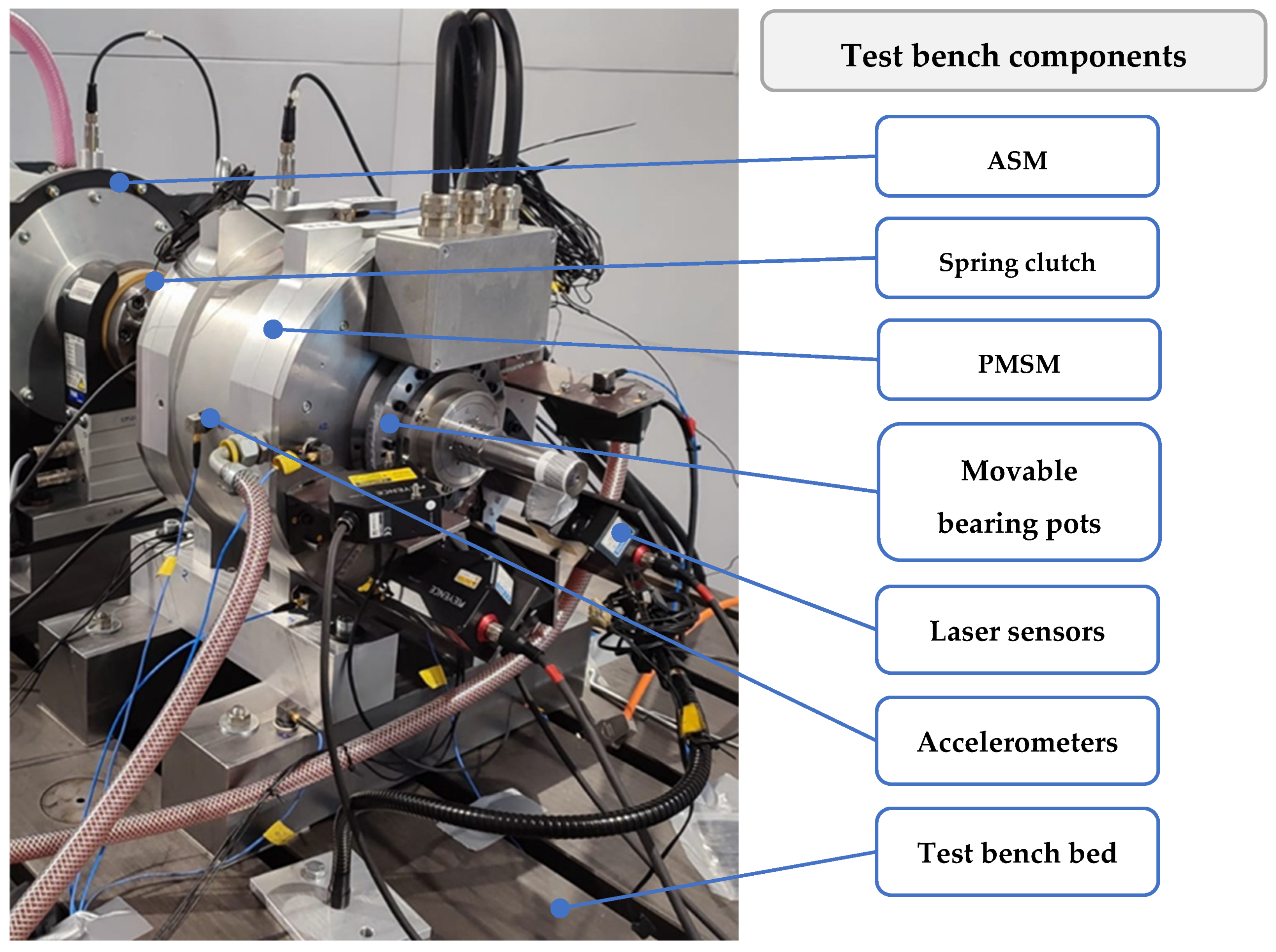
Section 1, the rotor is offset eccentrically to the stator due to manufacturing tolerances, resulting in sidebands in additional dynamic excitations which can be determined in the frequency spectrum as sidebands in addition to the main excitation orders of the electric machine. This static eccentricity shifts the force distribution within the electric machine, thereby altering the direction of the main excitation. Additionally, the rotor experiences centrifugal forces due to manufacturing-related imbalances, which increase quadratically with the rotor’s rotational frequency. The bearings exhibit nonlinear stiffness properties and air gaps, which depend on the manufacturing tolerances of both the rotor and stator. Consequently, to accurately measure the NVH behavior of an electric machine, it is necessary to account for the influence of all individual system components on the dynamic behavior of the electrical machine, as each has its own manufacturing-induced structural dynamic behavior. To investigate the influences of eccentricity on the NVH behavior of electric machines, a test bench for a permanent magnet synchronous machine (PMSM) was designed. This setup allows for the determination of the effects of eccentricity changes (see
Figure 1).
The PMSM under consideration is a custom-made electrical machine manufactured by the author’s institutes. It has 4 pole pairs and 48 teeth, with a maximum torque of 150 Nm and a maximum power of 63 kW. The test bench features movable bearing pots that enable each bearing to be independently adjusted radially by up to 0.2 mm. The displacement of the bearing pot is achieved using appropriate dowel pin pairs. This maximum displacement corresponds to approximately 30% of the prevailing air gap of the PMSM.
The PMSM is connected to another test bench machine (ASM) via a spring clutch and mounted on a common test bed. With each variation in eccentricity, the PMSM and the output machine are realigned to ensure no additional forces arise from axle misalignment in the clutch. In order to measure the influence of eccentricity on the NVH behavior of the electrical machine both the structural dynamics and the eccentricity have to be measured. The structural dynamic behavior of the electrical machine can be measured using accelerometers. Those measure the structure-borne sound at a fixed location on the housing. In order to measure the eccentricity laser sensors can be used to measure the location, displacement and deformation of the rotor. To capture the NVH behavior and the varying states of eccentricity, the sensor setup shown in
Figure 2 was used. Accelerometers from PCB with a sensitivity of 150 g and a maximum frequency range of up to 8 kHz were attached to the PMSM to record its acceleration behavior. These triaxial piezoelectric sensors detect surface acceleration in three spatial directions. To record the eccentricity state of the PMSM, three different cross-sections of the rotor’s position were monitored. For this purpose, the LK-H152 and LH-G15 lasers from Keyence were used with a sample rate of 24 kHz and a sensitivity of 0.3 µm at normal discretion. Two lasers offset by 90 degrees were positioned at each bearing heel, and an additional three lasers offset by 90 degrees were placed near the rotor sheet stack. The latter also allows for the determination of axial changes in static eccentricity.
For the measurements, the entire test bench setup was mounted inside an acoustic chamber to isolate the test environment from its surroundings. The associated test bench setup is shown in
Figure 3, illustrating not only the schematic representation of the sensors used in
Figure 2 but also all other cables, pipes and components of the test bench, which are required for operating and monitoring the test bench.
To control a speed ramp-up, the system is initially tensioned. The ASM controls the torque, which is measured by a torque sensor near the coupling and compared with the target torque of the ASM. The speed is then increased by regulating the PMSM during the ramp-up. The regulated currents are transmitted via a CAN bus signal to the high-frequency measurement system, which also records the data from the accelerometers and laser sensors. A separate vibration monitoring system for both electric machines continuously checks for impulses acting on the system. This, combined with the torque monitoring, triggers an emergency shutdown if needed, which is connected to the manual test bench control on the test bench computer. All measurement data are buffered in the internal storage of the high-frequency measurement system, ensuring the temporal synchronization of all data. After reaching the maximum speed, the measurement is completed, and the system is slowed down.
3. Determination of the Influence of Static Eccentricity
To measure the acoustic behavior of the PMSM, ramp-ups up to 5000 rpm at 100 Nm torque were performed. Both the rotation speed and the applied torque are the maximum operation conditions of the considered electrical machine. By applying those operation conditions, it is ensured, that the maximum of electromagnetic forces are applied at a wide frequency range. To ensure the reproducibility of the measurements, the test bench environment was preconditioned to 60 °C, and each measurement scenario was repeated three times since the temperature increased up to a maximum of 64 °C during one runup. This procedure ensures that the electric machine does not overheat during full-load operation, preventing changes in electromagnetic excitation forces and deformation of the PMSM due to heat.
During the measurements, the eccentricity is increased with a nominal increment of 0.04 mm five times (see
Table 1). This increment is based on the tolerance chain that was applied accordingly to Schröder et al. [
16] and represents the expected static eccentricity of the electrical machine due to manufacturing tolerances. Since the orientation of this manufacturing dependent eccentricity remains unknown, five eccentricity adaptions are applied to ensure that the investigated eccentricity states do not shift the eccentricity towards a concentric run. However, the set eccentricity states are also influenced by the dowel pin pairings used which are subject to further manufacturing tolerances.
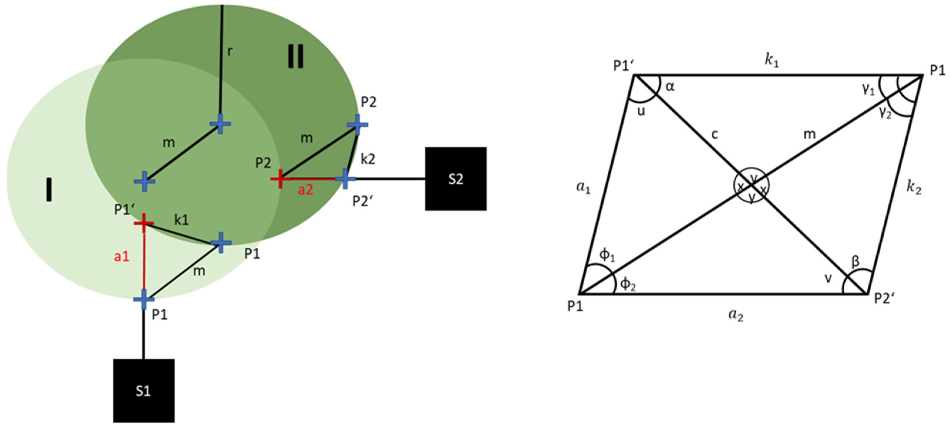
Therefore, it is essential to determine the absolute eccentricity change resulting from the variation in eccentricity states. For this purpose, the laser signals are considered. The change in eccentricity occurs in a radial direction and is detected by the lasers at the bearing points, which are each offset by 90°. However, the radial change in eccentricity is a two-dimensional problem. Considering that the surfaces of the shaft are not ideally cylindrical, the one-dimensional measuring lasers do not point perpendicularly to the moving surface of the rotor (see
Figure 4). This can lead to distortions in the measured eccentricity, especially considering that the interval of eccentricity change is smaller than the roundness tolerance of the shaft at the bearing seats.
The changes in the measurement signals of lasers S1 and S2 to states I and II are represented by the values a1 and a2 in
Figure 4. However, due to the curvature of the rotor, the displacement of the rotor center m resulting from a change in eccentricity cannot be determined from a1 and a2 using the Pythagorean theorem. Additionally, it must be noted that the lasers measure at different positions, leading to different curvatures for a shaft that is not ideally round. The geometric problem can be resolved by applying the cosine theorem to the geometric dependence shown on the right side of
Figure 4 and
Figure 5:
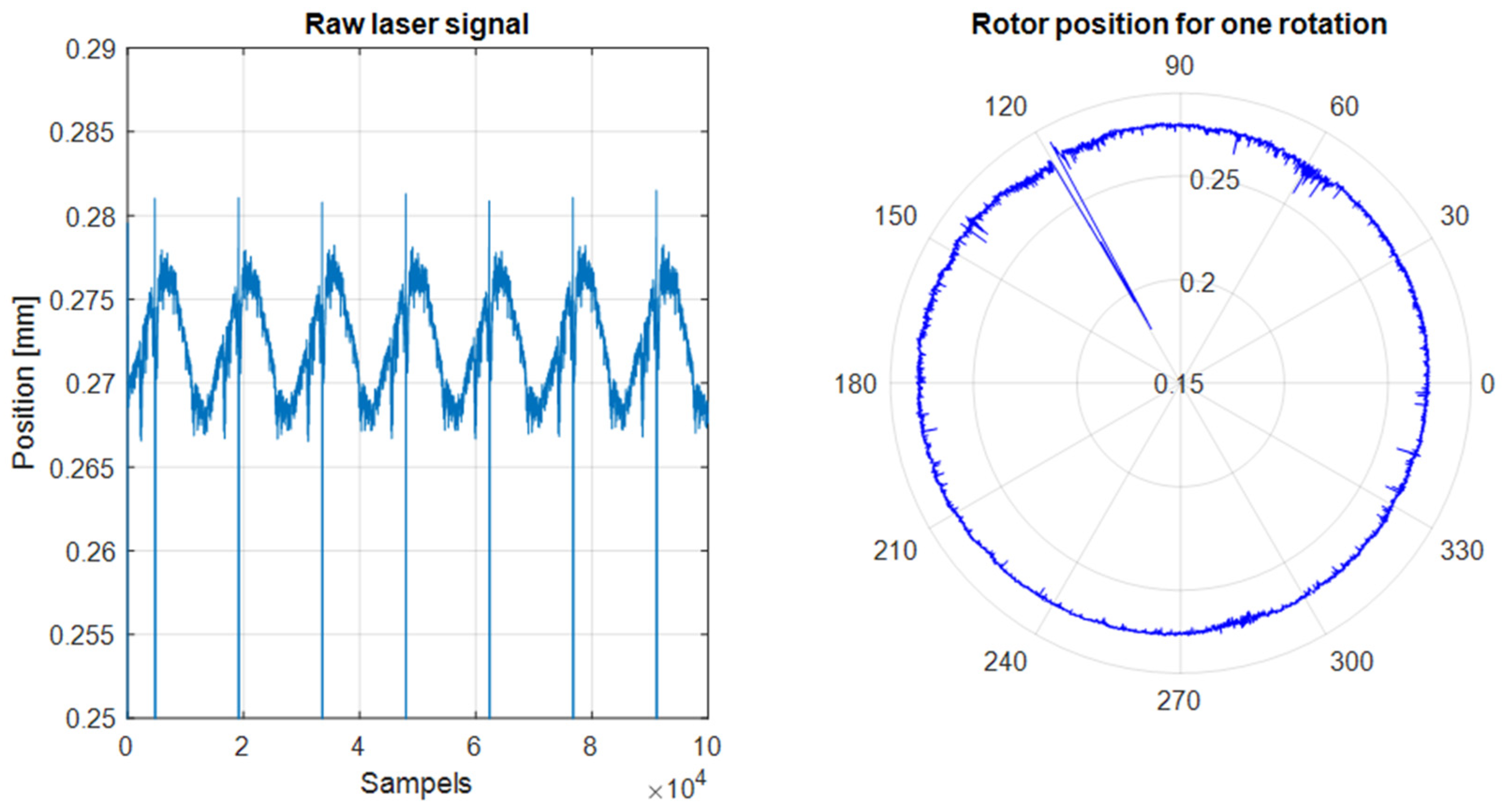
The only unknown factor in determining m is the curvature of the shaft at discrete points in time. However, this can be ascertained by examining the rotor in a quasi-static state, where the lasers record the geometry of the rotor cross-section.
Figure 5 shows an unprocessed laser signal from the S1 sensor at a speed of 100 revolutions per minute. At this speed, it is assumed that dynamic effects are negligible. Examining the time signal for 10
5 samples at a sampling rate of 24 kHz (left), it can be observed that the shaft exhibits a certain degree of unroundness that is detectable by the lasers. Additionally, a distinct notch with a significantly different amplitude from the average can be seen for each revolution. This notch was intentionally stamped on the shaft in advance to enable the lasers to detect the angular position of the rotor relative to the stator. This angular position allows for the precise determination of when the rotor has completed a revolution. Using this information, the rotor position for one revolution can be visualized (
Figure 4 right). Individual notches on the shaft surface are clearly visible, as well as the out-of-roundness or curvature depending on the angle. This laser measurement signal for one rotation is subsequently used as a mask (see
Figure 4 right) to determine the curvature of the laser signal and the actual change in eccentricity by comparing two masks of different eccentricity states.
In
Figure 6, the measured eccentricity changes for states 1 to 6 are shown for both the floating and fixed bearings. In each case, the eccentricity steadily shifts in the direction of sensor 5 (see
Figure 2).
For the following analysis of the influences of static eccentricity on the NVH behavior of electrical machines, two hypotheses are assumed: 1. The dominant influence of static eccentricity on the structural dynamic behavior of the PMSM is due to effects in the air gap, not due to changes in mechanical properties such as mass and stiffness distribution. 2. The temperature distribution that changes during the operation of the PMSM has no influence on the electromagnetics or on the static eccentricity itself.
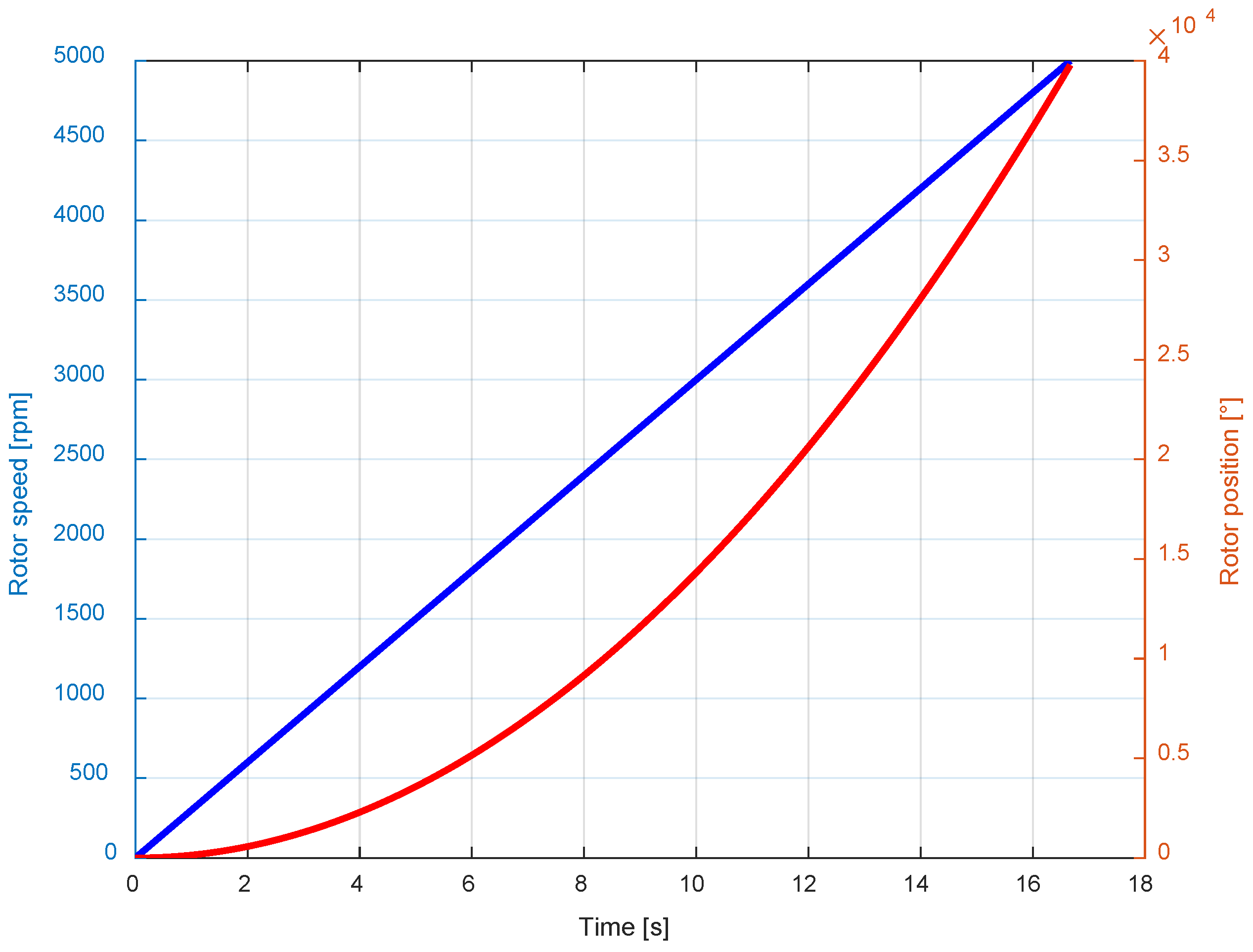
Figure 7 illustrates the corresponding speed profile and the rotor position, represented as an integral, as a function of time, with an acceleration of 300 rpm/s that was applied during the measurements. This relatively slow ramp-up was chosen to allow the system sufficient time to stabilize and avoid passing through acceleration-sensitive resonances. For simplicity, in the following analysis, acceleration signals will no longer be presented as functions of time but will be converted to the speed profile shown in
Figure 7.
In
Figure 8, the total levels of acceleration from sensor number 5 (see
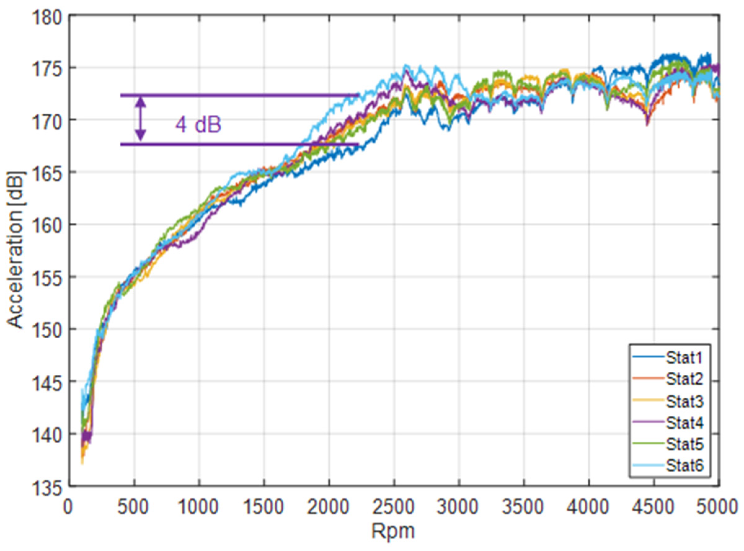
Figure 2) in the normal direction are shown as a function of the static eccentricity states. In the first static eccentricity state (Stat1), the critical operating point which is defined by the maximum surface acceleration level is around 176 dB between 4500 rpm and 5000 rpm.
The variation in the static eccentricity shows that both the maximum total level and the critical operating point change. A direct comparison between Stat1 and Stat6 shows that the total level as a function of the static eccentricity state varies by up to 4 dB at different speeds. Furthermore, each measured state of static eccentricity results in a different critical operating point, and there is no linear relationship between the eccentricity changes (
Figure 6) and the change in the overall level as a function of speed.
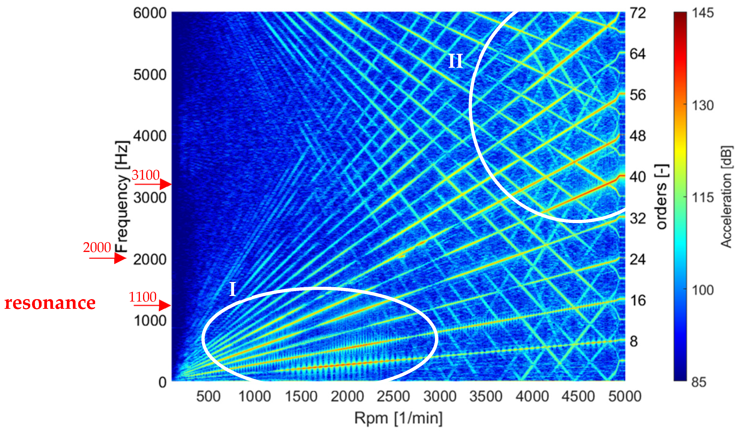
By analyzing the spectrogram of the acceleration signal from sensor position number 5 (see
Figure 2) in the normal direction for the first static eccentricity state (
Figure 9), it can be seen that two compartments are spreading with increasing rotation speed. The compartment of the electrical machine starts in the lower left corner of the spectrogram at low rotation speeds and frequencies. This compartment consists of the orders of the electrical machine, which represent multiples of the number of pole pairs and number of teeth and increase proportionally with the speed. The second compartment, which spreads out starting at 6000 Hz, contains the orders of the inverter, which decrease proportionally to the rotation speed of the electrical machine. Mirroring of these orders on the
x-axis at 0 Hz represents aliasing effects, which result from the measurement setup used and are not physically meaningful excitation orders. In comparison, the excitation orders of the electrical machine have a significantly higher acceleration level and are therefore more dominant in the overall level of the electrical machine. Consequently, the influence of the static eccentricity on the excitation orders of the electrical machine is examined in more detail below. The acceleration signal shows that the lower machine orders (8th, 16th, 24th and 32nd; see
Figure 9 reference I) have an increased acceleration level, especially in the low-speed range from 0 to 2500 rpm. In addition, higher orders (40th, 48th, 56th, 64th and 72nd; see
Figure 9 reference II) show a dominant share of the acceleration level during higher speeds. High acceleration levels at the same frequency but different rotation speeds represent resonances of the measured system, occurring, for example, around 1100 Hz, 2000 Hz, and 3100 Hz (see
Figure 9).
Comparing the acceleration signal of the sixth static eccentricity state (see
Figure 10) with that of the first static eccentricity state, it can be observed that, for instance, the 48th and 56th orders are much less dominant at higher speeds indicated by the reference I. However, the 56th order increases in dominance in the speed range from 1700 to 3700 rpm (see
Figure 10 reference II). In addition, the lower orders now seem to have a more dominant share of the overall level over a much larger speed range (see
Figure 10 reference III). Furthermore, sidebands to the main excitation orders, such as the 48th order and 56th, which were not present at the first eccentricity state, can be identified.
In summary, the comparison of the acceleration signals for the first and sixth eccentricity states shows that the dominant parts of the excitation orders in the resonances sometimes occur over a much wider frequency range or appear weakly in previously dominant frequency ranges. From these differences, it is assumed that either the resonances of the system or the excitation amplitudes of the electromagnetic forces, or both, must have changed as a result of the variation in static eccentricity. Since the shown spectrograms in
Figure 9 and
Figure 10 are a relatively unprecise visualization of the frequency content of the acceleration signal and differences can only be identified optically, a comparison of the relevant order levels follows in order to identify the influences of the static eccentricities in greater detail.
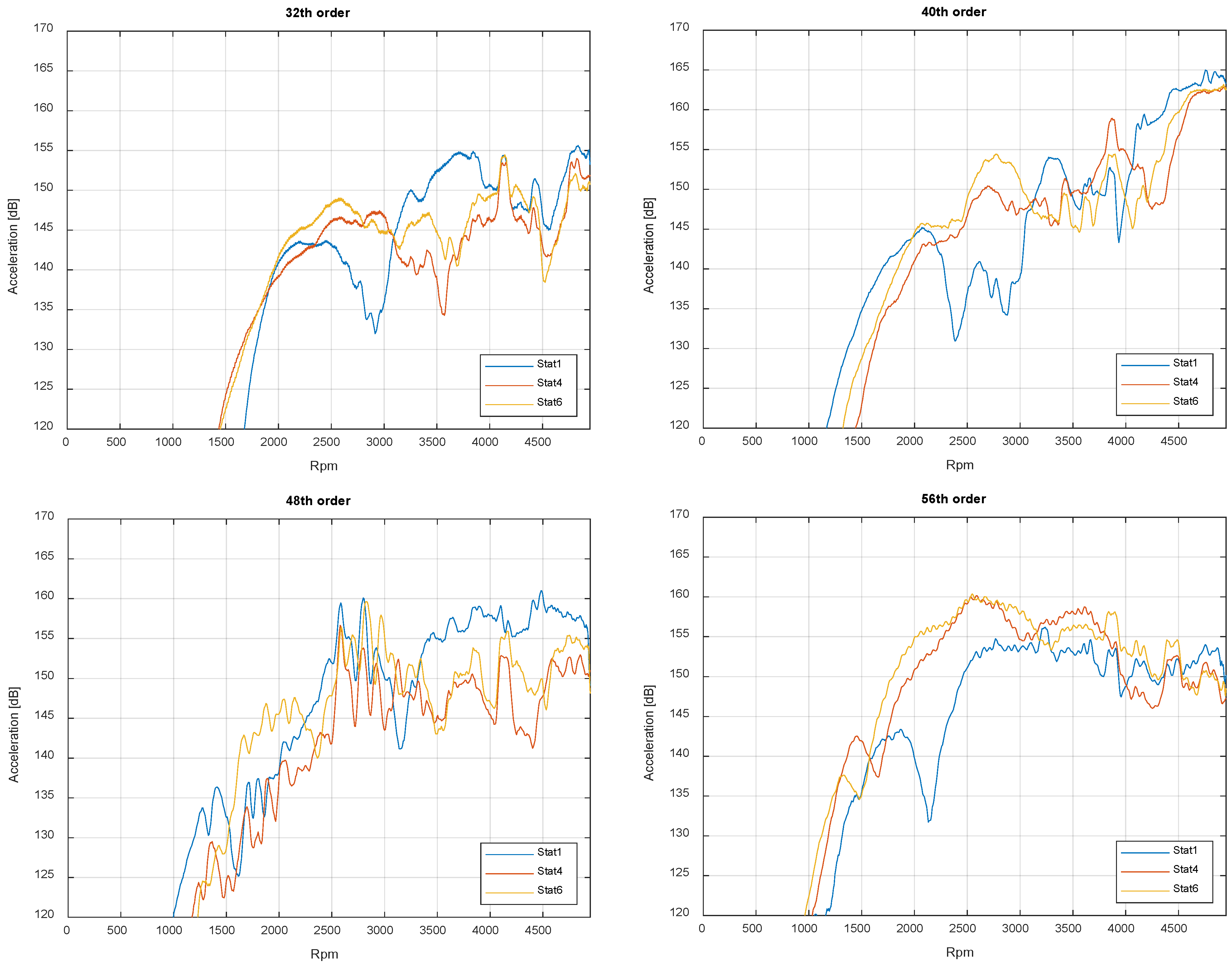
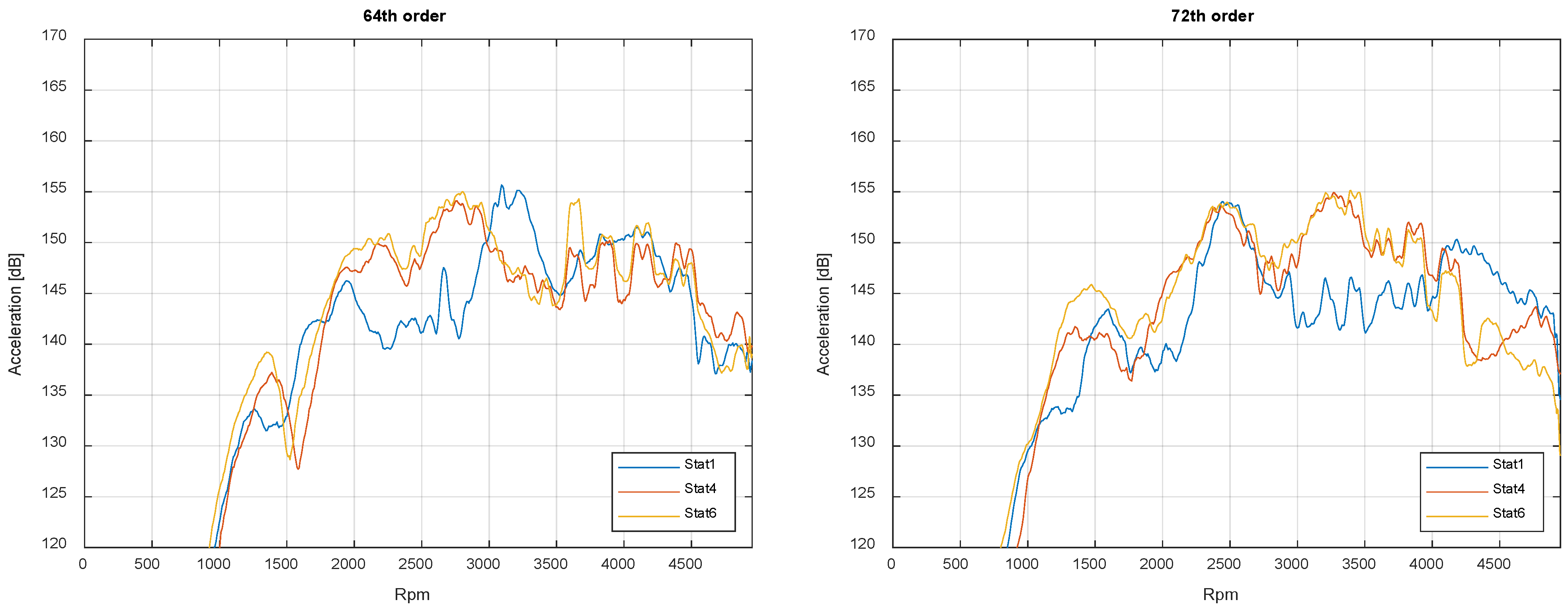
Figure 11 illustrates the various order levels of the electric machine that are significantly affected by changes in static eccentricity for the eccentricity states Stat1, Stat4, and Stat6. Lower and higher machine orders seem to be hardly influenced by eccentricity, and therefore, they are not discussed further. All order levels exhibit a speed-dependent difference in the double-digit dB range, with a maximum of 24 dB at the 56th order at approximately 2200 rpm. The significant variation in order levels depending on static eccentricity demonstrates how sensitive the overall system is to this single manufacturing parameter. Additionally, eccentricity influences when an order level reaches its speed-dependent maximum and thus becomes relevant in the overall structure-borne noise level (see
Figure 6). This is mainly due to the two effects that can be observed in the order levels: change in excitation amplitude and shift in resonances.
The order level of the 48th order for the eccentricity states Stat1, Stat4 and Stat6 clearly shows that at higher rotation speeds, the order level is significantly reduced at higher static eccentricity. Additionally, from 2500 to 3000 rpm, there is a shift in the local order level maxima to a higher rotation speed, suggesting a stiffening of the system. There is also a clear difference in the order levels for the two eccentricities in the range of 1500 to 2200 rpm, which can further indicate stiffening. A similar shift can be observed at the 72nd order at 2500 rpm, although shifting to lower rotation speeds indicates a softening of the structure. Since the mode shapes of the electrical machines cannot be measured with the sensor setup used, a sufficient comparison of all modes of the electrical machine is not feasible. Therefore, in the case of large differences between the order level at different eccentricity states, for example, that displayed in the 40th order plot at a speed of 2700 rpm or the 64th order plot at a speed of 2700 rpm, they cannot be unequivocally attributed to either of the two effects.
However, the 56th order shows a significantly higher level throughout the entire middle rotation speed range at the static eccentricity state Stat6. This is mainly due to an increase in the excitation force since no resonance peaks are indicated in the graph of the order level. The same behavior can be observed for all order levels up to a maximum rotation speed of 1500 rpm.
In summary, the acceleration behavior of the sensors on the electric motor housing is significantly influenced by static eccentricity. The speed-dependent dominance of the excitation orders at the total level, as well as the order level, changes notably, indicating a change in the system resonances and excitation amplitudes due to changes in static electromagnetic forces. It should be noted that although the sidebands that occur with increasing eccentricity (see
Figure 9 and
Figure 10) are visible in the spectrograms, the changes in the main excitation orders seem to be more relevant for the acoustic behavior of the electrical machine. It can be concluded that the dominance of the level within a specific frequency range significantly depends on the eccentricity in the overall level. However, there is no linear relationship between the increase in static eccentricity and the change in acceleration behavior. Additionally, the mode shapes of the PMSM cannot be determined with the current sensor setup, preventing a comparison of the mode shapes and natural frequencies as a function of static eccentricity.
4. Conclusions and Outlook
In the scope of this publication, a methodology was introduced to systematically explore the impact of static eccentricity on the NVH (noise, vibration, and harshness) characteristics of an electric machine. A PMSM equipped with radially adjustable bearing wells, allowing targeted variation in static eccentricity of up to 0.2 mm, was investigated. Laser sensors, capturing the rotor cross-section at three positions, facilitated the determination of eccentricity changes during quasi-static states. Comparative analysis of acceleration order levels revealed that the speed-dependent dominance of the machine’s excitation orders varied significantly with the set eccentricity state. The measured overall level exhibited a difference of up to 4 dB, while the order levels showed a difference of up to 28 dB, depending on the manufacturing-induced eccentricity across various speed ranges. The displacement of local maxima in order levels was found to correspond to shifts in critical operating points of the electric machine. The shift in resonances and the change in excitation amplitudes due to eccentricity changes were discussed as two main influencing effects. Despite experimentation, no correlation was established between increased eccentricity and changes in acceleration behavior. However, numerical models could be developed by using experimental data of varying eccentricity states in order to improve the accurate prediction of simulated NVH behavior of electrical machines and to address their optimization efficiently. This absence of correlation might be attributed to inherent manufacturing eccentricity present in the machine at the initial Stat1 eccentricity state. This manufacturing eccentricity, estimated statistically at 40 μm based on a tolerance chain, remained undetectable throughout the investigations, potentially leading to a temporary approximation of the machine to a concentric state during eccentricity changes. Moreover, deviations in magnetization within the rotor’s permanent magnets could result in asymmetrical magnetic fields, potentially affecting the machine’s excitation characteristics in conjunction with non-ideal sinusoidal currents. Although the general importance of static eccentricities for total acceleration level and sound design can be extended to other electrical machines further experimental inquiries are warranted to scrutinize the influence of radial eccentricities, as well as the axial tilt of the rotor and magnetization deviations on the NVH behavior. However, the test bench and measurement setup for such experiments must ensure that potential interdependencies between geometric eccentricities in the radial and axial directions can be clearly distinguished from magnetic eccentricities. Additionally, consideration must be given to how other factors, such as slippage in asynchronous machines, may supersede the effects of eccentricities. Thus, methodologies that can discern various influences on the NVH behavior of different types of machines are indispensable.
The findings underscore static eccentricity as a pivotal parameter in the NVH optimization of electric machines. The sensitivity of dominant frequency ranges underscores the importance of manufacturing tolerances in sound design for electric vehicles. Furthermore, it has been demonstrated that precise prediction of excitation characteristics and structural dynamic behavior of electric machines poses major challenges for optimizing sound radiation from drivetrains and transfer paths to other components.
