Energy demand has been drastically increasing on a global scale and to accomplish a sustainable future, the development of renewable energy systems is necessary [
1]. To tackle climate change on a large scale, it needs to be acknowledged that our global economic system is mainly based on fossil fuels, more specifically, oil for all the transportation sector, and coal and gas for electricity generation. However, while fossil fuels become scarcer, the method used to obtain these resources turns more extreme and aggressive with our ecosystem. In today’s technology, we can find the right tools and techniques to develop a more sustainable energy landscape [
2]. The research of innovative optimization strategies and the implementation of new technologies for renewable energy systems is crucial for sustainable development. Wind energy is considered one of the most efficient and cost-effective renewable energy sources, with offshore wind farm projects increasing in recent years due to their vast energy density and reliability [
3,
4]. The implementation of direct-drive generator structures for offshore applications is common for producing more efficient systems, preventing the use of a gearbox, reducing the weight of the structure, and decreasing failure rates. In open sea locations, the simplification of the system is an important factor to account for considering the harsh environmental conditions and inaccessibility [
5]. The costs of development of offshore wind turbine farms are high and the optimization of these projects at an early stage is of significant interest to developers and manufacturers [
6]. New and more innovative optimization approaches for offshore wind turbine projects are in high demand to overcome the challenges involved in the design of the different components integrating these systems [
7,
8,
9,
10,
11] and the current supply chain issues.
1.1. Direct-Drive Wind Turbine Generators
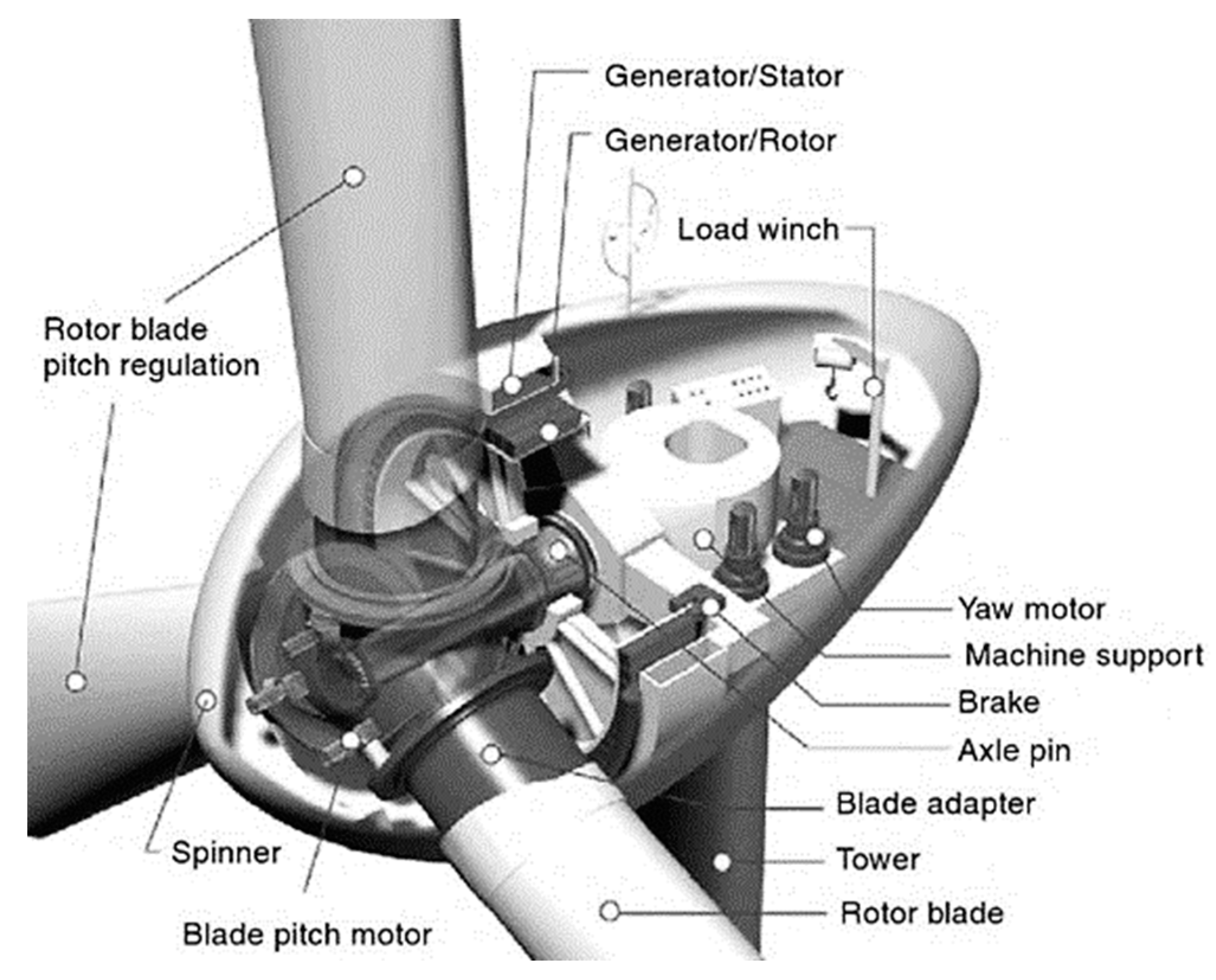
Large direct-drive generators are rotational electrical machines operating under high electromagnetic and gravitational loads. In
Figure 1, we can observe a representation of a direct-drive, wind turbine, electrical machine configuration with different components forming the design.
Direct-drive generators are AC synchronous electrical machines and can be excited electrically or through permanent magnets. These types of generators are classified depending on the direction of the magnetic flux crossing between the rotor and the stator structure; the three different configurations are axial flux, transverse flux, and radial flux, with the former configuration representing the most popular choice for offshore wind turbine generators [
13,
14]. Direct-drive generator structures work under high torques while rotating at low speed, and this requires high levels of structural stiffness to keep the deformation below the established limits of 10% through the air gap length “
z” between the rotor and stator of the generator [
12].
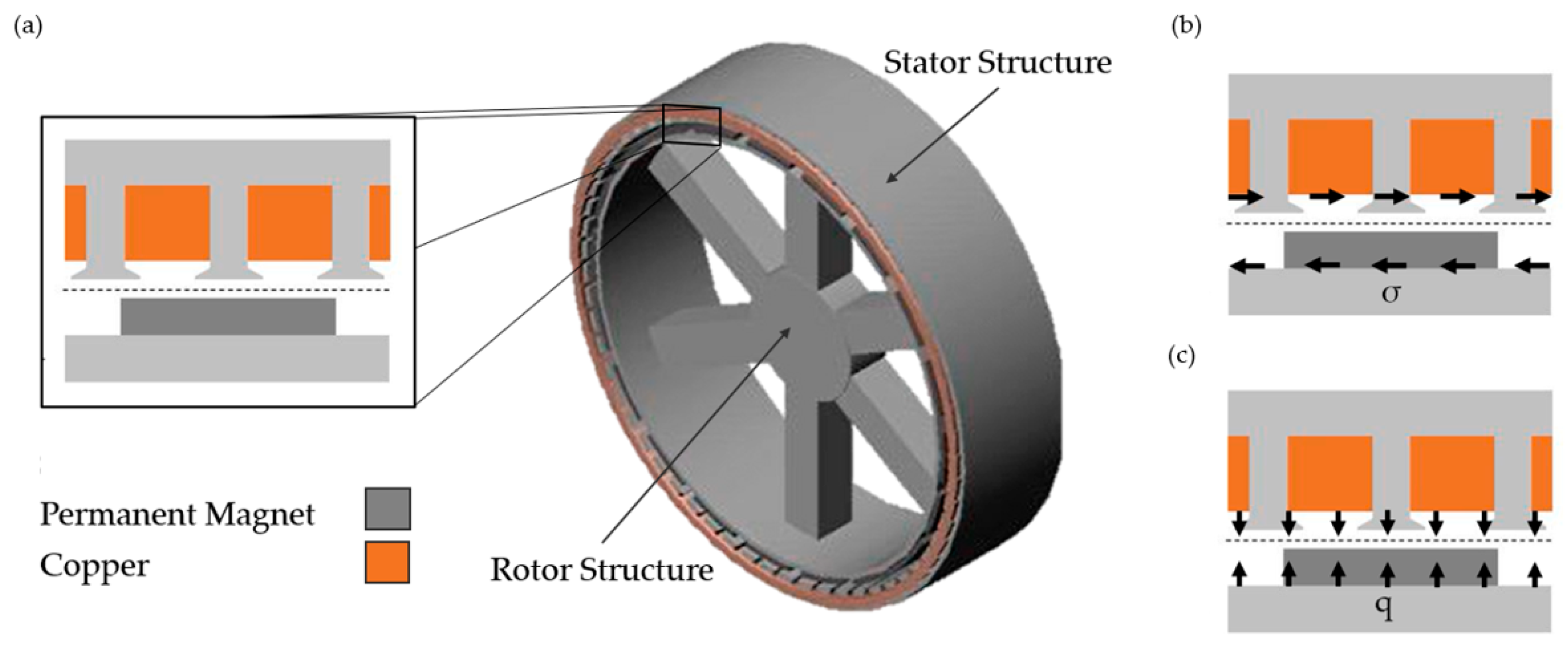
The main loads generated upon a direct-drive generator structure under working conditions are represented in
Figure 2. Maxwell stress “
q”, or normal stress, is the electromagnetic force generated in the direction of the magnetic flux across the air gap between the rotor and the stator, having a typical value of 200–400 kPa for these electrical machines. Shear stress “
σ” is the force generated perpendicular to the magnetic flux, having a value of 25–50 kPa. The third main load to consider for the structural analysis of direct-drive generators is the gravitational load [
13].
Direct-drive generator structures are large components typically made of steel, which account for over 60% of the overall mass of the system, opening the door to ambitious optimizations through high-performance structural analysis strategies. These specific requirements and the harsh operational conditions constitute a great challenge to the structural design of these machines [
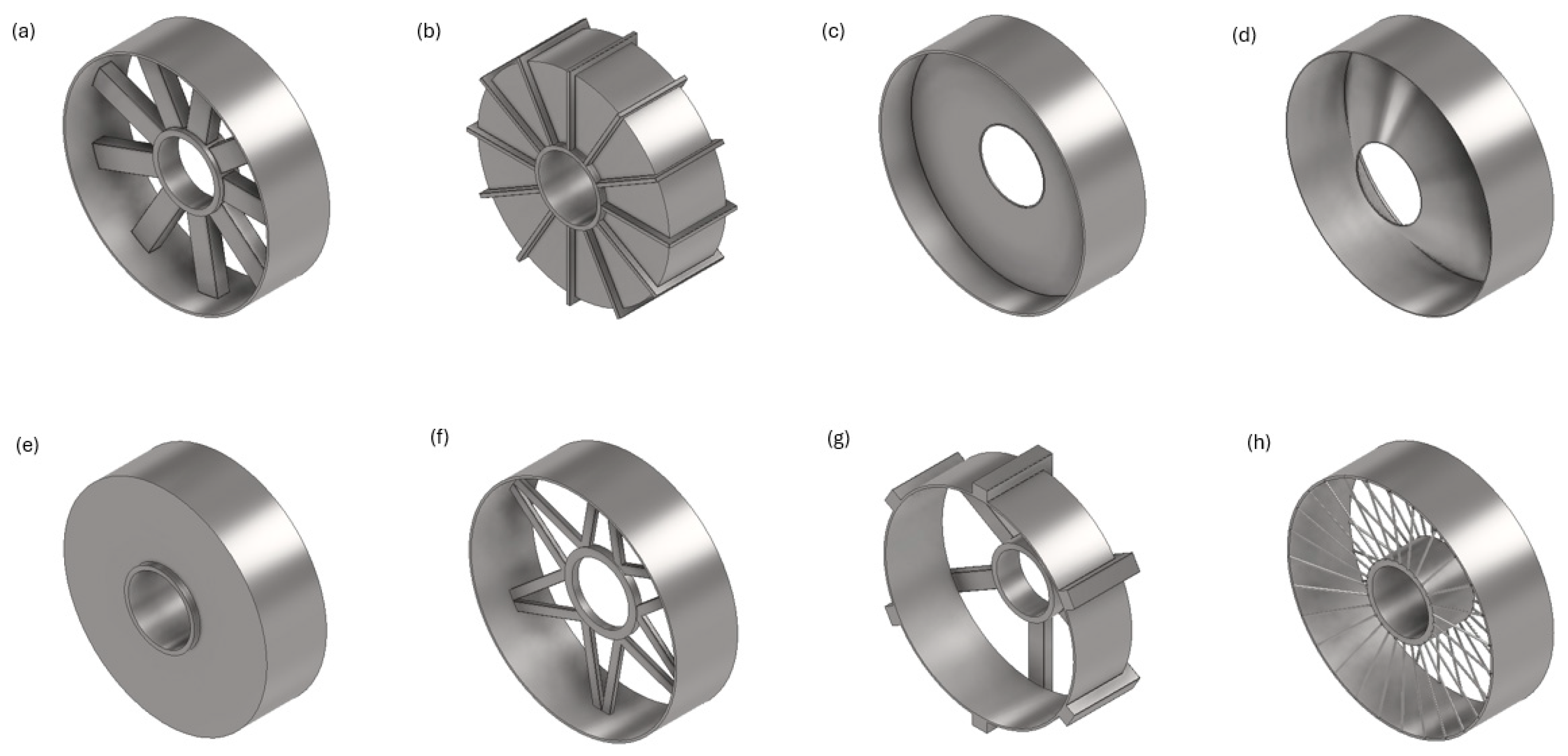
12]. Different support structures for direct-drive generators have been explored through the implementation of simple topologies (discs, cones, and arms) designed to be manufactured commonly in cast iron [
15]. The representation of a review of conventional structures can be observed in
Figure 3. Advanced optimization techniques such as generative design constitute an innovative approach to overcoming complex multi-objective structural challenges of direct-drive generators and have been implemented to discover nonconventional structural configurations [
16,
17].
1.2. Additive Manufacturing
New optimization methods allow engineers to explore nonconventional topologies and, with the development of innovative manufacturing techniques, for the fabrication of these novel topologies to become a reality in the form of high-performance and lightweight structures.
Additive manufacturing is a general term used to describe a fabrication process, which generates, layer-by-layer, a physical object from model data [
18]. Additive manufacturing is capable of generating highly efficient, complex parts, that are otherwise unfeasible to obtain by conventional manufacturing methods. This process of manufacturing consists of adding material through the process of building up a three-dimensional model directly from computer-aided design software, in opposition to conventional manufacturing, which focuses on subtracting techniques [
19]. New progress in additive manufacturing technologies allows the production of nonconventional structural configurations. The recent development of metal additive manufacturing has experienced significant growth, driving innovation in design optimization techniques across different high-profile sectors, such as the aerospace industry, the automotive industry, and the energy sector [
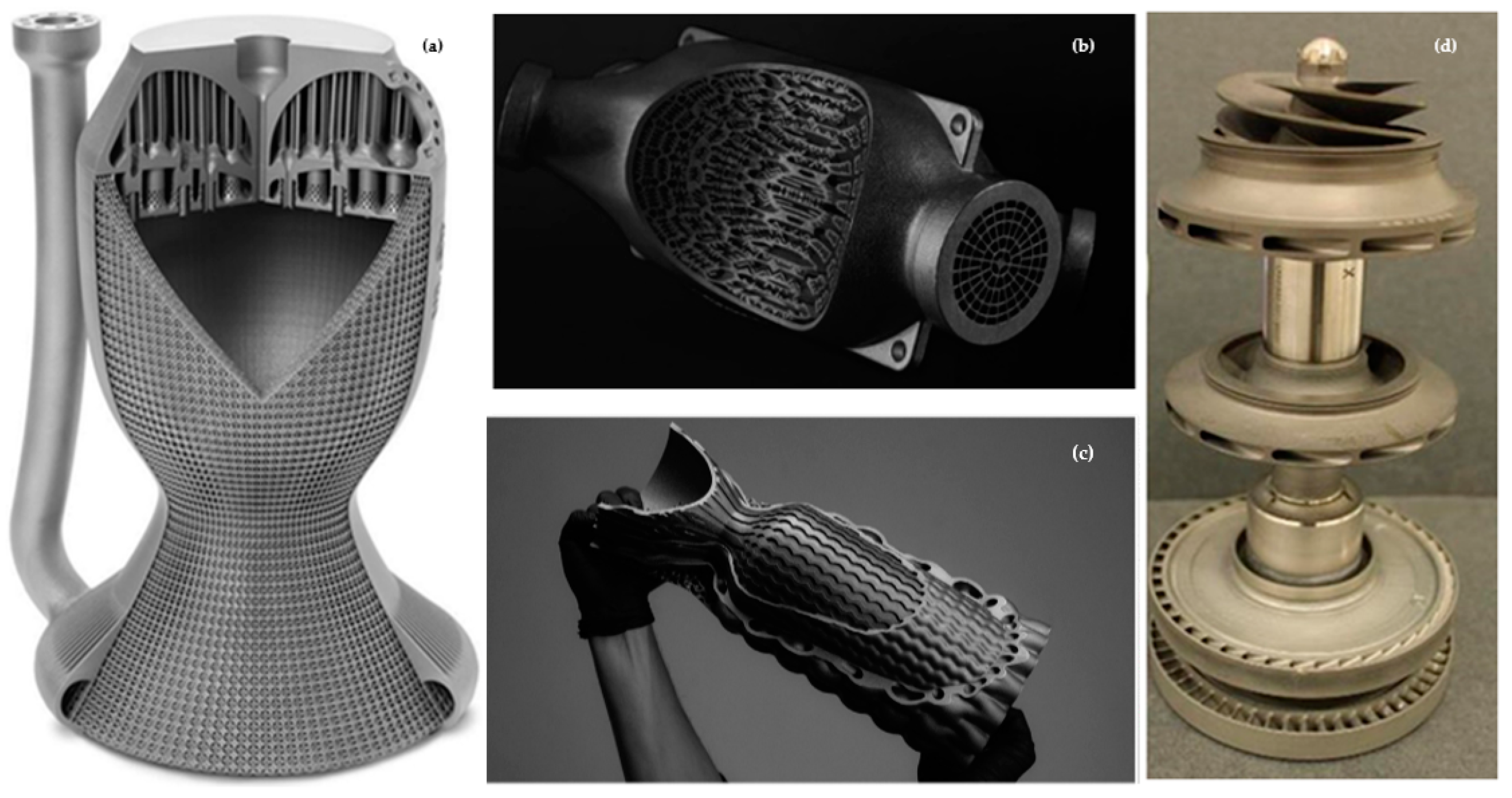
20]. In
Figure 4, we can observe the result of the implementation of additive manufacturing processes for different high-performance components. Complex designs can be achieved through additive manufacturing methods coupled with advanced optimization strategies linked to algorithmic methods, such as generative design, to efficiently redistribute the mass of the part, which improves mechanical, thermal, and dynamic performance [
16].
Laser powder bed fusion (L-PBF) is one of the most popular metal additive manufacturing processes, characterized by a high level of precision and short lead times with a minimum feature size of 0.2 mm and large building volume, with new commercial machines achieving just under 1 m
3 of volume. The laser powder bed fusion process uses powerful lasers, with some commercial machines having up to 12 lasers of 1000 W each [
21], to melt layers of metal powder and using materials such as steel alloys, aluminum alloys, and nickel and iron superalloys [
22].
Figure 4.
Implementation of additive manufacturing approaches for the development of high-efficiency components over diverse disciplines [
22]; (
a) Prototype rocket nozzle featuring internal cooling channels; (
b) F1 heat exchanger; (
c) Hyperganic prototype rocket nozzle featuring internal cooling channels and an external lattice; (
d) Liquid hydrogen and liquid oxygen turbopumps by NASA.
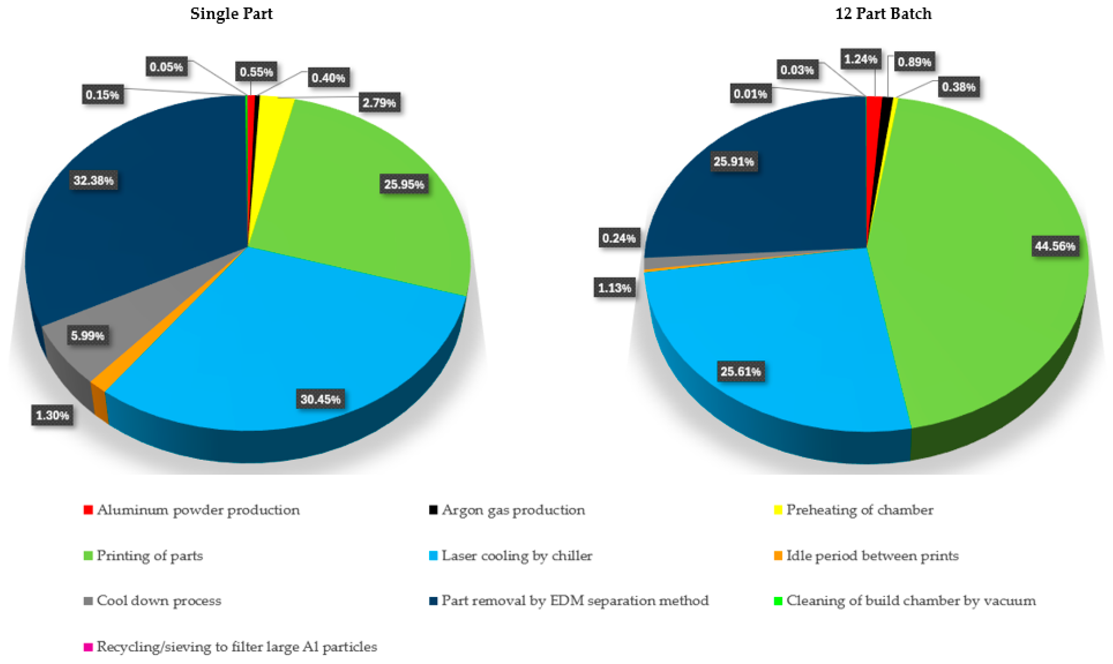
Understanding the additive manufacturing process is fundamental to achieving the full potential of this new technology. Acknowledging the energy efficiency of a manufacturing process is important to assess the energy usage during the full manufacturing process. To evaluate additive manufacturing processes in comparison to conventional subtracting processes, it is necessary to establish different parameters, such as production costs or environmental impact [
23]. In
Table 1, the energy consumption for each stage of a selective laser melting process is described for the production of a single part and for the production of a batch of 12 parts [
24]. In
Figure 5, an example of energy efficiency assessment has been addressed with a visualization of the energy consumption percentages for a metal additive manufacturing process using selective laser melting (SLM) technology and AlSi10Mg as printing material.
Figure 5 shows the importance of the build volume optimization during an SLM process on the energy efficiency of the production of the printed part, with a 55.64% total energy consumption reduction per part when producing a batch of 12 parts against a single part production.
The consideration of a design for an additive manufacturing (DfAM) approach during a structural optimization strategy in order to improve the efficiency of the production and the sustainability of the process is essential. Integrating additive manufacturing constraints into structural optimization strategies allows the development of more efficient, sustainable, and fit-for-purpose processes. Simulation-driven design for additive manufacturing and, more precisely, selective laser melting processes, such as laser powder bed fusion (L-PBF), represents a breakthrough in the fields of design optimization for metal 3D printing components. L-PBF possess multiple advantages in comparison with conventional manufacturing methods for structural optimization methods of highly efficient metal components. Some benefits of L-PBF applied to optimization processes are a decrease in lead times, waste material reduction, design flexibility, and on-demand production, with great performance on lightweight applications. The recent development of L-PBF commercial machines allows the comparison of metal additive manufacturing against conventional manufacturing techniques and highlights the advantages of using this process [
25,
26]. SLM commercial machines such as the NXG XII 600 present a step further toward metal additive manufacturing mass production and incrementing the number of lasers up to 12 to achieve a process 20 times faster in comparison with other SLM machines. This new technology development has been addressed in several academic and industrial investigations across different fields in the last few years [
27].
In [
24], the energy efficiency of the additive manufacturing process is discussed, where manufacturing parameters such as additional support structure could increase energy efficiency by over 45% and bulk part production optimization pushing the energy efficiency even further. Optimization strategies focusing on metal additive manufacturing at a design stage could revolutionize the industry, drastically reducing material waste, energy consumption, and production costs [
28]. The implementation of additive manufacturing constraints over design optimization strategies has a direct impact on the manufacturing stage and the overall sustainability of the production [
29].
Additive manufacturing has been applied for the structural optimization of direct-drive generators in [
30,
31], where triply periodic minimal surfaces were employed for the generation of the lattice topology using evolutionary algorithms, and mass reduction of the generator structure was observed.
1.3. Potential Applications: Multirotor Wind Turbines
The power rate and scale of the systems within traditional horizontal axis wind turbines have been substantially increased recently. Some of the most important logistical challenges of these large wind turbines are those associated with large-scale blades of over 100 m long and structural components, such as the big steel structures of direct-drive generators [
32]. The multirotor configuration demonstrates an improvement in efficiency and a reduction in overall loads, although it introduces a larger number of moving parts in the system [
33]. The multirotor wind turbine concept offers an alternative to increasing the power output of the machine by combining multiple rotors into a single wind turbine. This configuration has been assessed to be 80% of the cost of an equivalent power rate single rotor wind turbine and over 8% higher on power output than a single rotor with an equivalent swept area. The major advantage of this configuration is the standardization offering a modular design in which the systems could be upscaled or adapted to the environmental conditions of the location, with standardized components being easily replaceable [
34]. Due to the advantages presented by the multirotor wind turbine system, new companies such as Myriad Wind Energy Systems [
35], as well as established multinationals, such as Vestas [
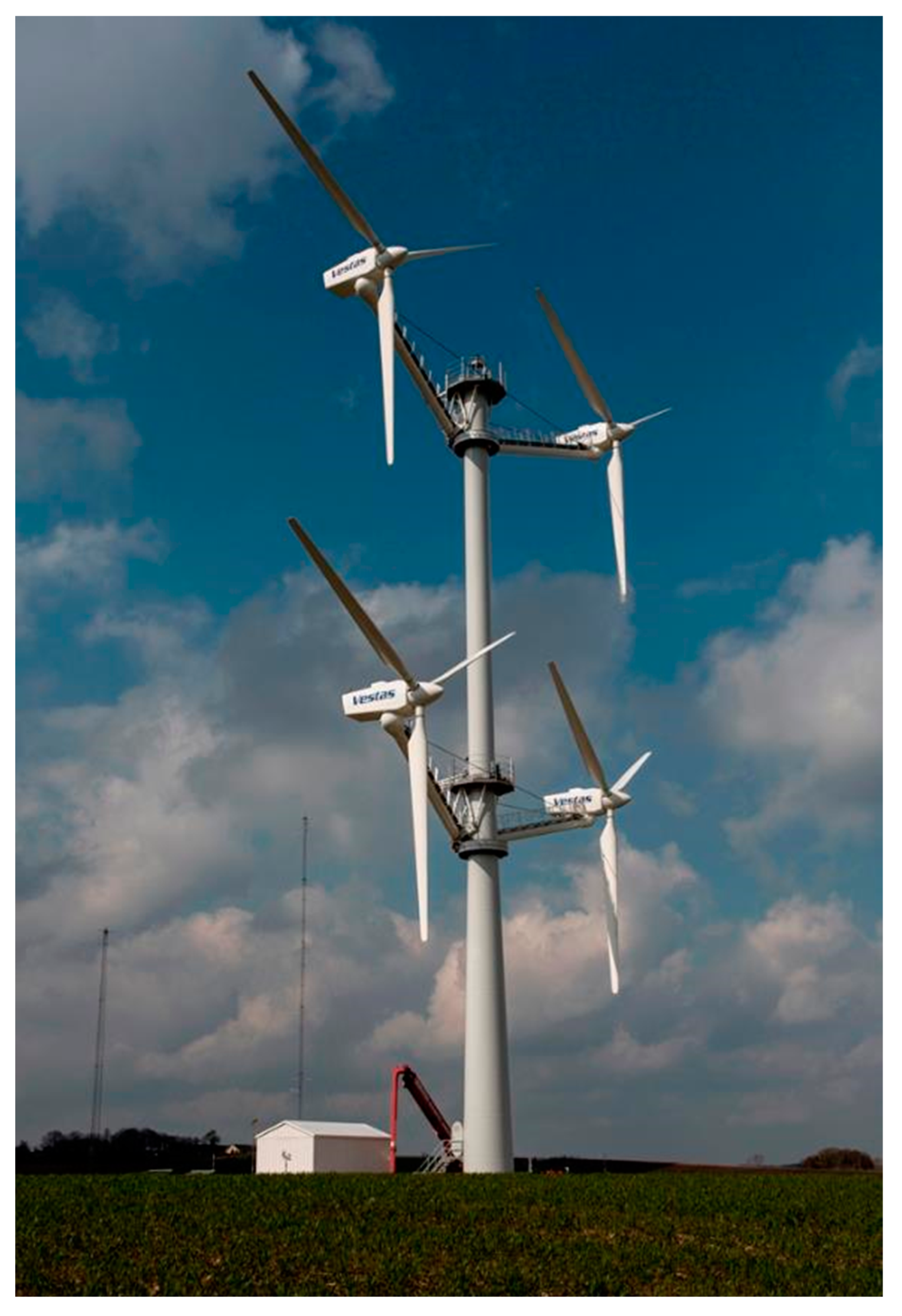
33], are adopting this unconventional wind turbine configuration.
Figure 6 shows a multirotor wind turbine built and tested by Vestas as part of the review performed for future emerging technologies in the wind power sector [
33].
A small generator structure implemented on the Vestas multirotor wind turbine opens the door to alternative and innovative manufacturing processes, such as additive manufacturing, as part of a modular, efficient, and more sustainable wind turbine configuration. In [
36,
37], steel structures and structures made with composite materials are explored for direct-drive generators. The 100-kW generator considered in this study is based on the electrical machine explored in [
36] and possesses a rotor diameter of 0.5 m with a cylinder width of 150 mm. The challenges associated with the design of the support structure of a permanent magnet direct-drive electrical generator (PMDD) require the careful assessment of the design parameters in order to develop an efficient structural optimization strategy. The high torques generated in these electrical machines demand a great level of structural stiffness. The parameters of a 3-MW and a 100-kW PMDD electrical generator are described in
Table 2, following the considerations in [
16,
17,
36,
37].
New commercial metal additive manufacturing machines integrate building envelopes big enough to manufacture the generator structure of these wind turbine rotors as one single part. One example of a large-envelope metal additive manufacturing machine is the SLM NGX XII 600, with a building envelope of 600 × 600 × 600 mm [
21]. The 3-MW generator support structure, with a 2-m rotor diameter, represents a challenge to be manufactured by current commercial additive manufacturing methods due to its size. A modular design with a design for an additive manufacturing approach holds great potential for future research on 3-MW generators.
1.4. Structural Optimization Strategy
An integrated structural optimization strategy consists of a large set of design analysis data involving the selected structure and its environmental conditions [
17]. Performing a complex three-dimensional structural optimization requires an advanced stress package embedded in a modelling piece of software, such as the one used in this study, ANSYS Workbench 2022. Structural optimization is a combination of multiple mathematical algorithms representing different aspects of the design specifications, optimization objectives, dynamic behavior, boundary conditions, or manufacturing constraints [
39].
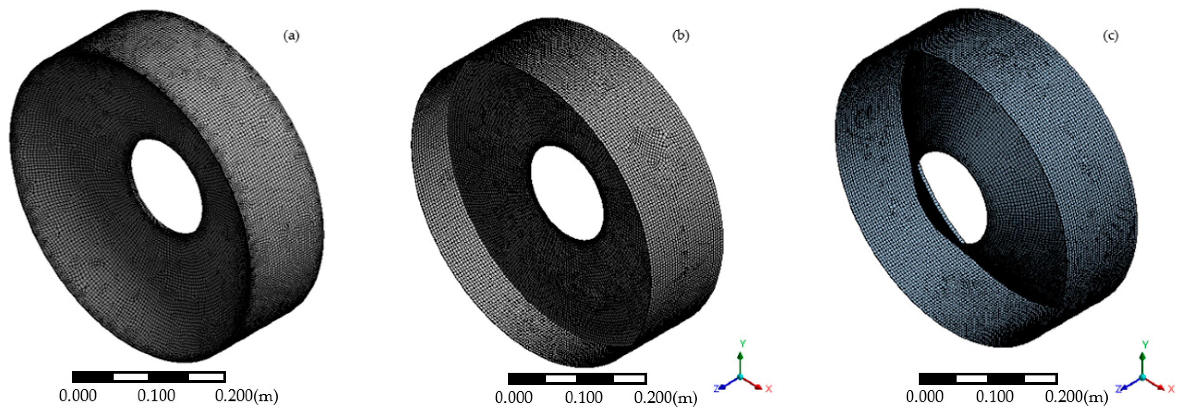
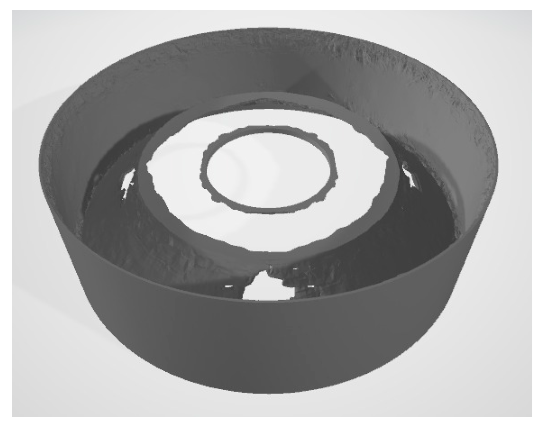
In a structural optimization process, the initial optimization volume represents the range of volume in which the software performs the optimization study. Depending on the software or the parameters, this volume can be described, or the software can determine it automatically. The initial optimization volume range is represented in
Figure 7.
On a structural optimization strategy for a direct-drive generator structure, maintaining the air gap deformation is crucial. Therefore, the primary criteria for the structural optimization strategy, as in [
17], is determined by the limit of deformation through the air gap between the rotor and the stator. In Equation (1), we can see a strain-based function used in structural optimization, where “Ω
mat” represents the volume of the material, “
ε” represents the strain, “
u” is the displacement, and “
σ” is the density [
39].
The considerations of structural vibrations of a rotational machine are fundamental for the optimization strategy. A modal analysis needs to be performed and integrated into the optimization strategy in order to identify and modify the natural frequencies of the structure and avoid the effect of resonance. Vibrations on rotating machinery need to be minimized to avoid fatigue, noise generation, and ultimately catastrophic system failure [
17]. The major excitation frequencies to consider for a direct-drive wind turbine generator are the turbine rotation speed “
1P”, the electrical frequency “
fe”, and the frequencies generated by the rotor blades “
3P” and “
6P” [
38].
A complex three-dimensional model requires the assessment of a modal analysis, in which the natural frequencies of the structure are identified and compared against the excitation frequencies of the system. The method used by the modal analysis to identify the frequency modes affecting the dynamic behavior of the structure is known as the effective mass participation factor (EMPF), in which the mass participation for a specific direction can be determined for each natural frequency mode of the structure. A frequency mode is identified as dangerous when over 1% of the participation mass is contributing within the operational range of the wind turbine [
17]. A modal analysis is integrated as part of the advanced structural optimization strategy to optimize the structure, avoiding dangerous frequency modes [
40].
An example of the algorithm used in the modal analysis can be seen in Equation (2), where “
ηr“ is the generalized mass of mode
r, “Ω
mat” represents the volume of the material, “
φr” is the load participation factor of mode
r, “
fmag” is the spatial distribution of the displacement and magnetic force, “
ωr” is the frequency of mode
r, and “
ωext” is the harmonic excitation frequency [
39].
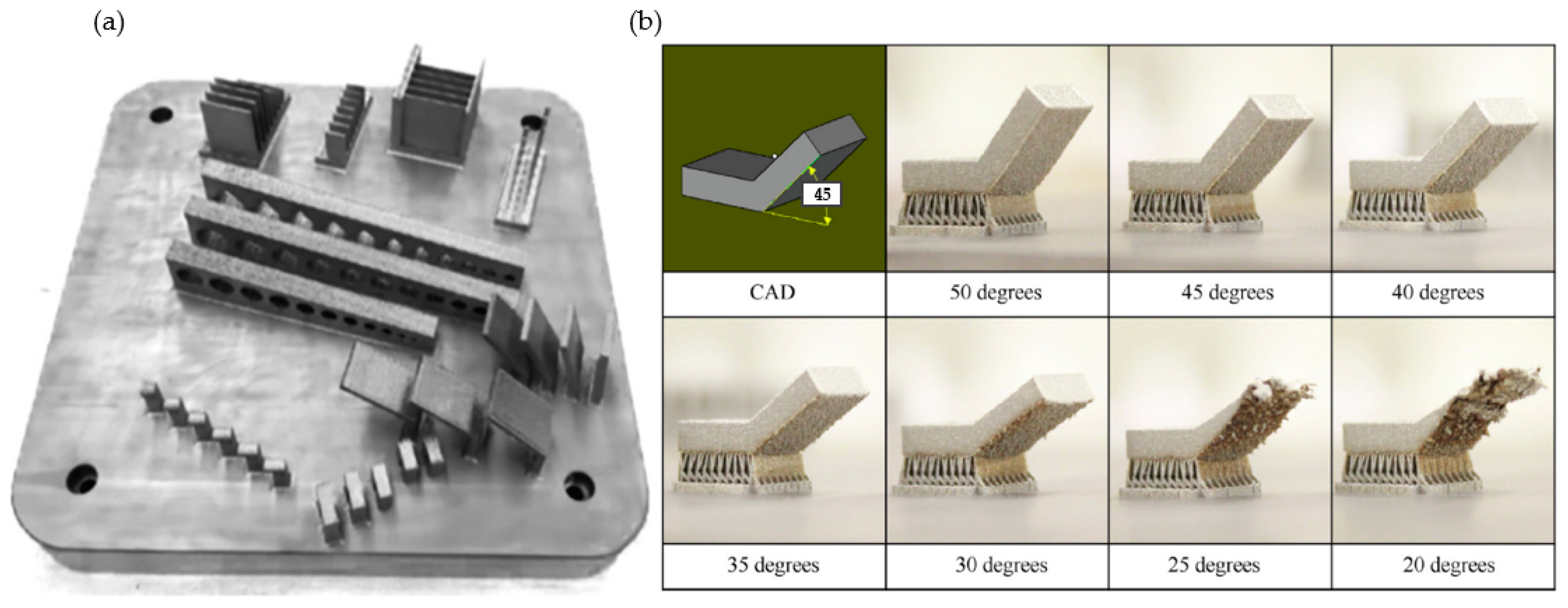
Introducing additive manufacturing constraints into the structural optimization strategy is fundamental to achieving an optimal result model. The implementation of design for additive manufacturing (DfAM) practices is essential to incorporating this new manufacturing knowledge into advanced structural optimization techniques for high-efficiency results [
41]. In
Figure 8, different additive manufacturing tests, such as design guidance, can be observed.
Manufacturing constraints such as overhang angle are essential to produce efficient result models while performing structural optimization techniques for additive manufacturing applications. The overhang angle constraint represents the minimum angle to accomplish the design performance required, obtaining the minimum surface finish intended or avoiding part failure. In
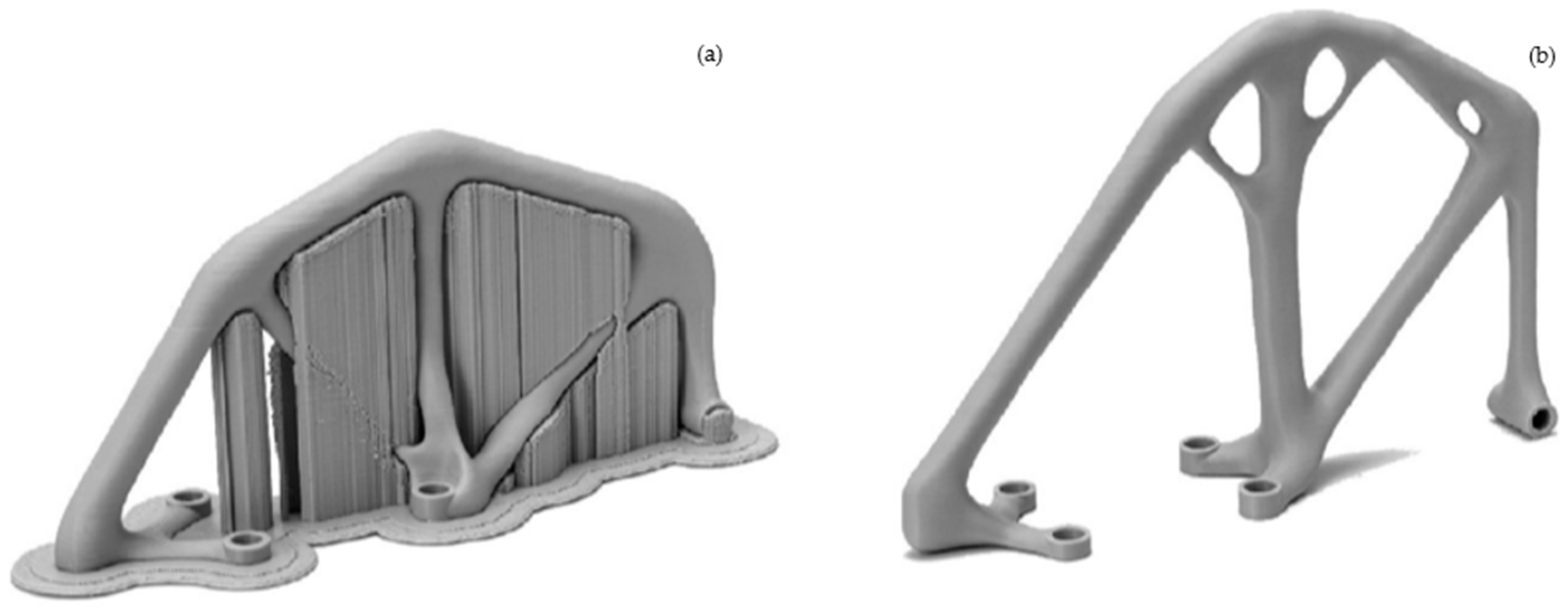
Figure 8b, we can observe the results at various overhang angle values. Considering design for additive manufacturing while developing a structural optimization strategy centered on the use of generative design techniques is an efficient approach that can lead to the generation of complicated designs. An example of the design for additive manufacturing is shown in
Figure 9, where the consideration of additive manufacturing constraints generates a self-supported structure, avoiding the need for additional supporting structure and reducing waste material, production costs, and manufacturing time.
Adding all the previously mentioned functions and constraints into an advanced, multi-objective, structural optimization strategy produced an adaptable and efficient method of analysis. Nonetheless, the complexity of the optimization strategy is proportional to the computing cost needed and needs to be considered through the iteration process [
42].
An integrated structural optimization strategy has been developed based on the studies [
16,
17] for a 100-kW permanent magnet direct-drive, wind turbine generator structure [
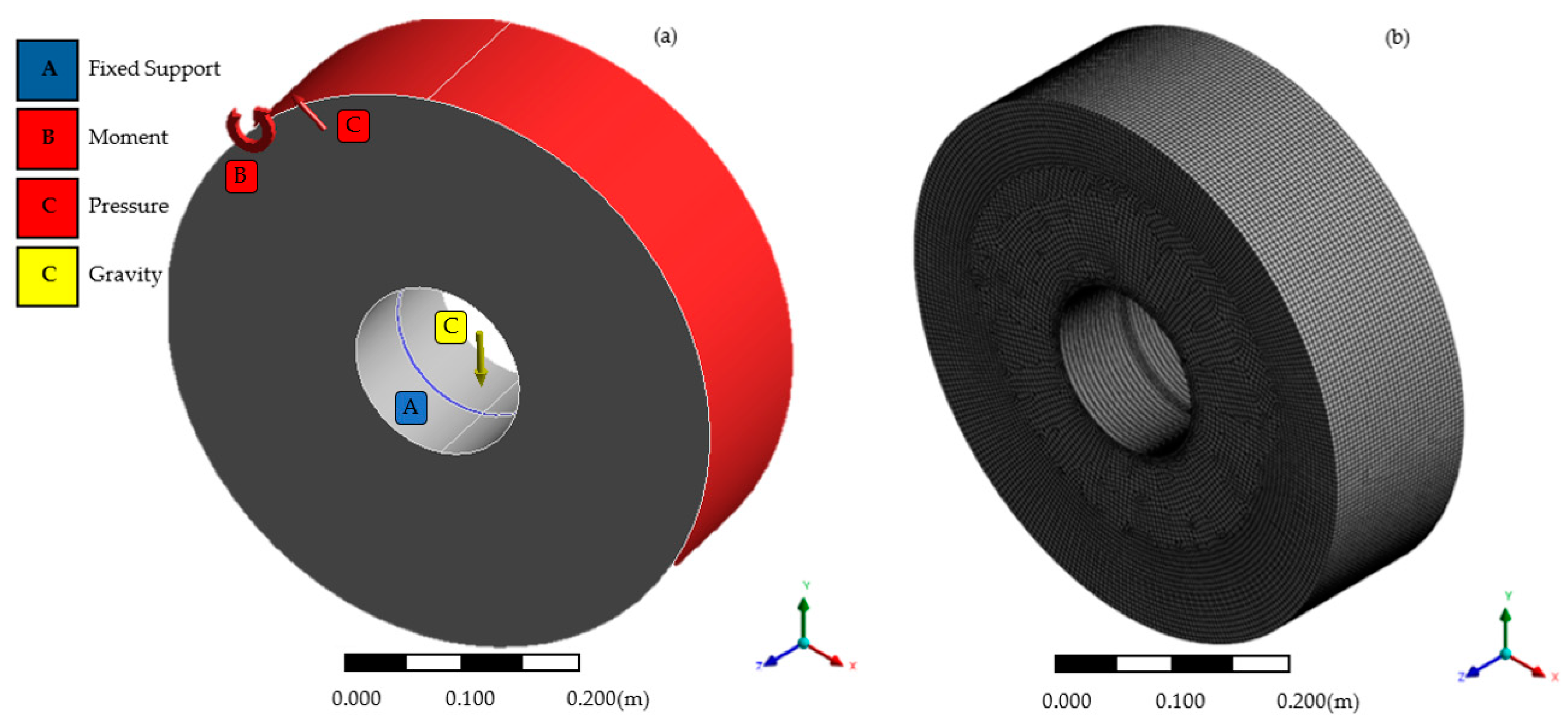
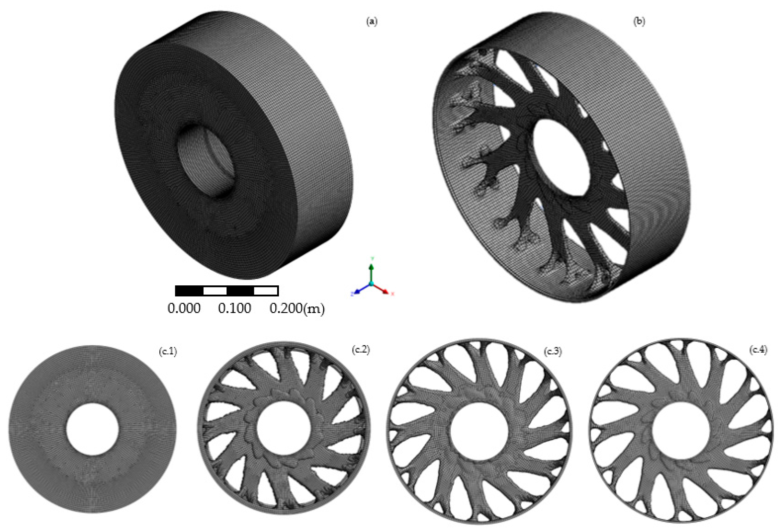
36]. A generative design process has been used, combining a static structural analysis and a modal analysis using the commercial software packages ANSYS for the structural optimization process and Fusion 360 for the additive manufacturing process simulation.
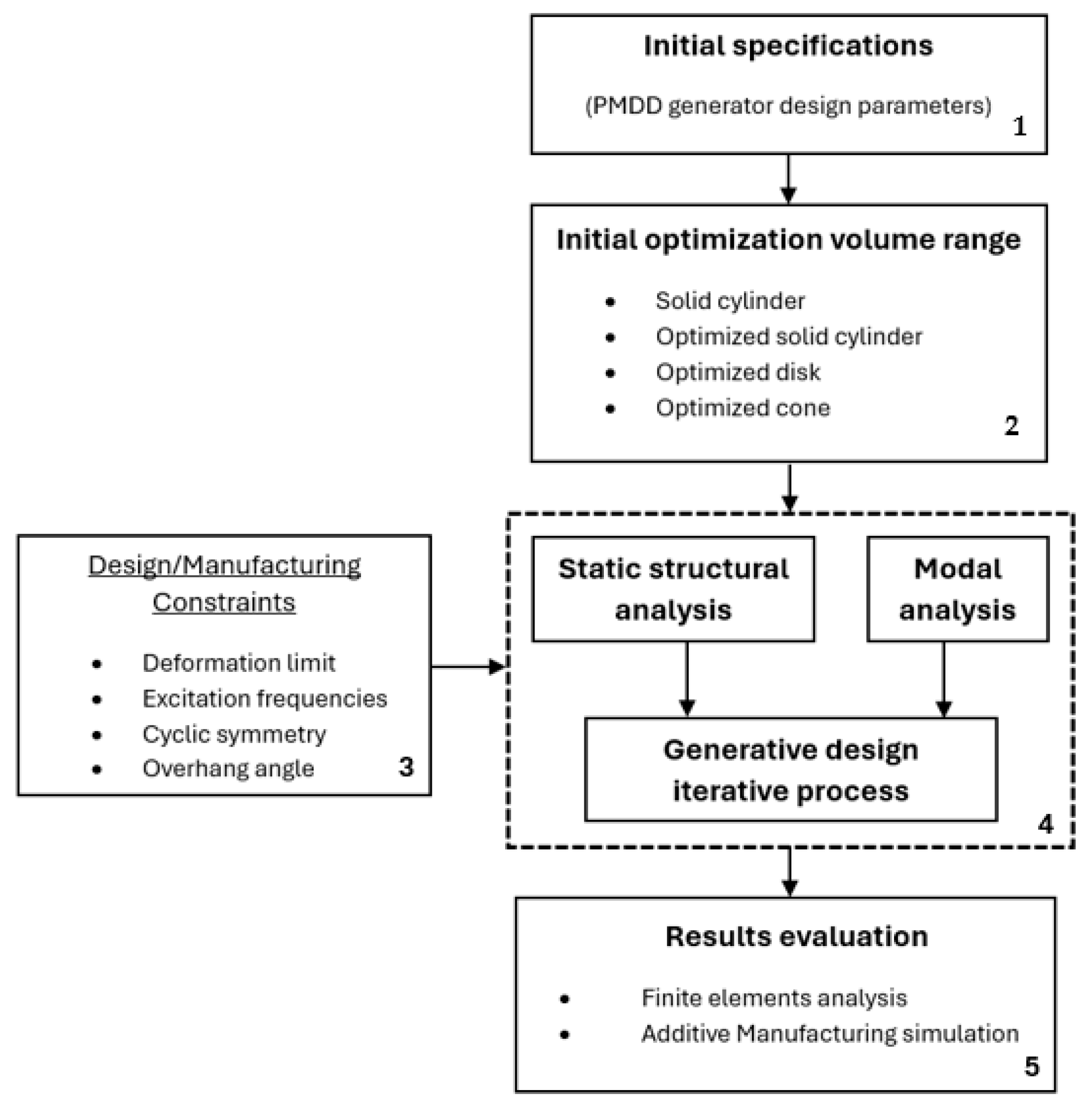
The process starts by determining the electrical generator design parameters and specifications, the considerations for the diverse optimization volume ranges for the different approaches, and the integrated structural optimization strategy, including the static structural analyses, the modal analyses, and the design and manufacturing constraints as part of the iterative generative design stage.
A workflow of the structural optimization strategy developed in this study has been represented in
Figure 10, where we can see the different steps followed during the process. The structural optimization strategy consists of:
The initial specification parameters of the direct-drive generator structure to be optimized.
The consideration of the different initial optimization volume ranges for the diverse approaches.
The design and manufacturing constraints strategy as objectives for the structural optimization process.
The development of the iterative generative design process integrating static structural analyses and modal analyses.
The evaluation of the results obtained from finite element analysis techniques and a metal additive manufacturing process simulation study.
The aim of this study is to develop an advanced structural optimization strategy based on the methodology produced in the investigations presented in [
16,
17], making use of generative design techniques that consider static structural and modal analyses and include a design for the additive manufacturing approach.
This novel design and manufacturing structural optimization strategy represents a zero-waste approach that integrates not only the optimization of the structures but also the optimization of the intended manufacturing process, virtually reducing the material waste to zero and significantly reducing the energy and water usage during fabrication. The integrated consideration of the latest developments in technology, both for computational structural optimization and manufacturing techniques, is a novel approach for complex engineering applications, such as the design of the support structures of permanent magnet direct-drive electrical generators.
