3.1. Asymmetrical 8/6 SRM Drive Design Principles
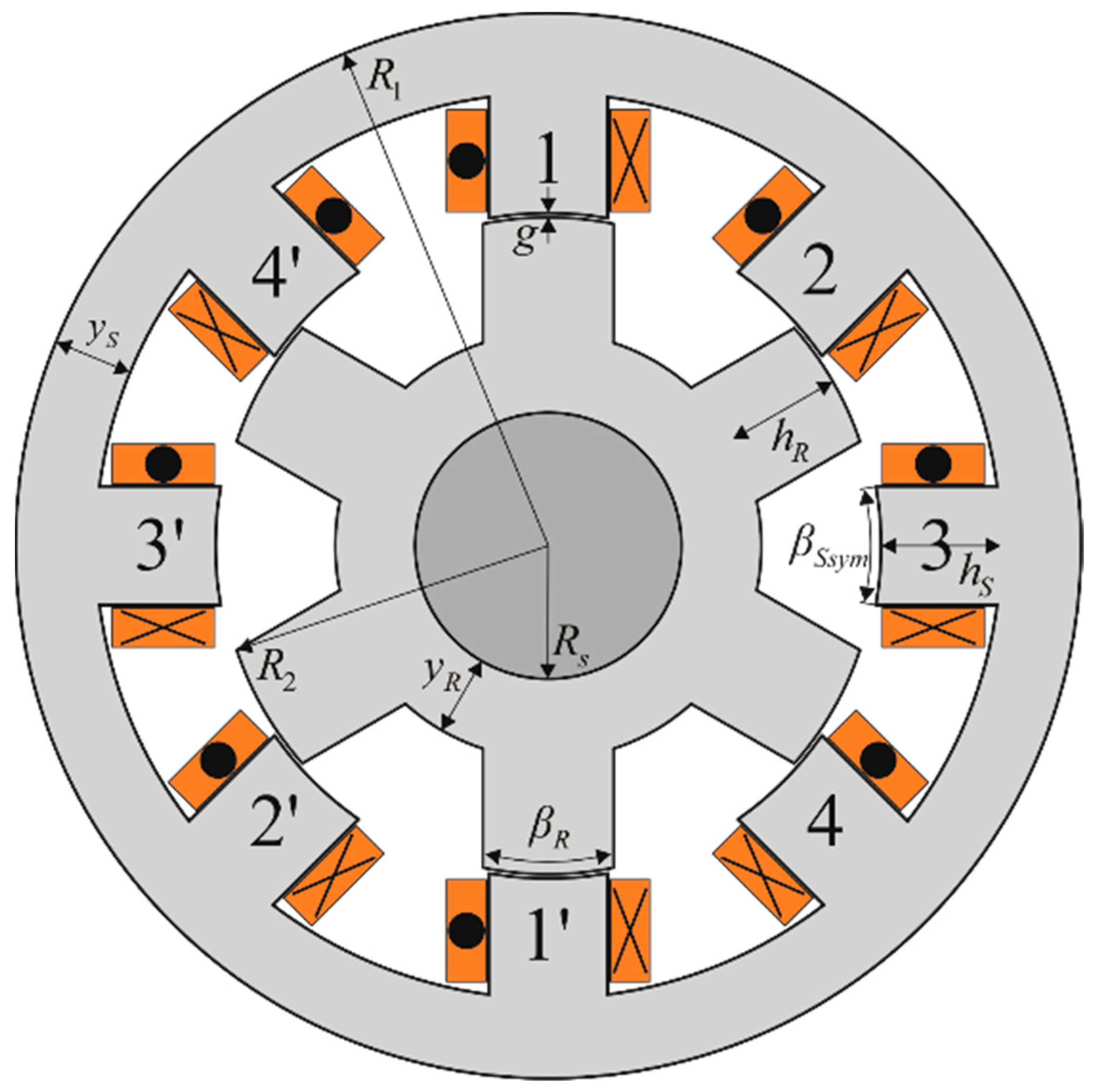
To introduce the asymmetrical 8/6 SRM, we start from the symmetrical 8/6 SRM displayed in
Figure 1 with the parameters given in
Appendix A. According to
Figure 1, the slot cross-section area is defined as
where
tSsym = 2(
R2 +
g)∙sin(
βSsym·π/360) is the stator pole width expressed in millimeters. The symmetrical 8/6 SRM holds
Nsym/2 coil sides of one phase in each slot, with
Nsym being the total number of coils per phase. The total slot area occupied by conductors is
where
AwCu is the total conductor cross-section area (including insulation).
The slot fill factor can be expressed according to (1) and (2) as
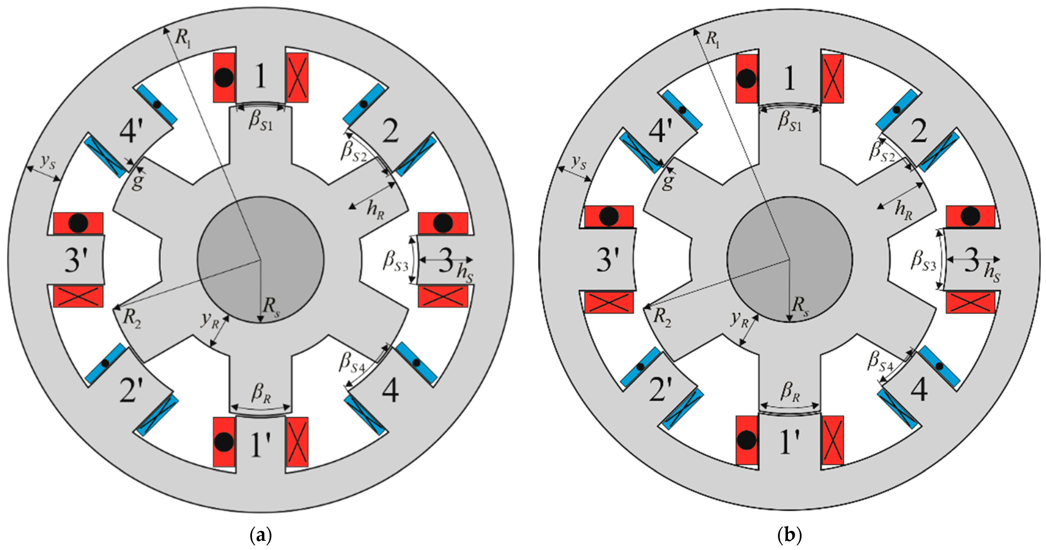
The asymmetrical 8/6 SRM concept is displayed in
Figure 2. The orthogonal phases 1 and 3 have the same number of turns
N1 =
N3 =
N13 and stator pole span
βS1 =
βS3 =
βS13. The same holds for the other orthogonal phase pair (phases 2 and 4), namely,
N2 =
N4 =
N24 and stator pole span
βS2 =
βS4 =
βS24.
Two variants of the asymmetrical 8/6 SRM are analyzed and compared. In the first variant (variant 1), as shown in
Figure 2a, orthogonal phases 1 and 3 have a higher number of turns compared to the symmetrical design (
N13 >
Nsym), whereas the orthogonal phases 2 and 4 have a lower number of turns (
N24 <
Nsym). The stator poles of phases 1 and 3 span the same or a smaller angle compared to the symmetrical design (
βS13 ≤
βSsym), whereas the opposite holds for phases 2 and 4 (
βS24 ≥
βSsym). The second variant (variant 2) differs from the first in terms of stator pole widths. In variant 2, the stator poles of phases 1 and 3 span a larger angle than the poles of the symmetrical configuration (
βS13 ≥
βSsym), whereas the poles of phases 2 and 4 span a smaller angle (
βS24 ≤
βSsym). The other parts of the magnetic circuit in both variants are unchanged compared to the symmetrical configuration, according to condition (ii).
According to
Figure 2 and the machine cross-section, in an asymmetrical 8/6 SRM with
NS = 8 stator poles,
NS/2 poles have a width of
tS13 = 2(
R2 +
g)·sin(
βS13·π/360), whereas the widths of the remaining
NS/2 poles equal
tS24 = 2(
R2 +
g)·sin(
βS24·π/360). It should be noted that condition (ii) must be satisfied, which translates to
All slots of the asymmetrical 8/6 SRM have the same cross-section area given by
whereas the coil-filled area of the slot equals
The fill factor of the asymmetrical 8/6 SRM is determined as
If a constant
K is defined as
to simplify given relationships, and considering that the fill factors of the symmetrical and asymmetrical 8/6 SRM are mutually equal, Equations (3) and (7) can be combined to obtain the following relationship:
After introducing coefficients, for the sake of easier manipulations,
and
the previous expression can be formulated as
Equation (12) defines the relationship between the number of turns and stator pole width of the symmetrical and asymmetrical 8/6 SRMs. When βS13 = βS24 = βSsym, (12) reduces to k13 + k24 = 2, which verifies derived relationships.
Condition (iv) defined in
Section 2 states that the ohmic per-phase losses of the asymmetrical 8/6 SRM may not be greater than the corresponding losses of the symmetrical 8/6 SRM, which is expressed as
where
R13 =
R1 =
R3,
R24 =
R2 =
R4, and
RSsym are the phase winding resistances, and
I13 =
I1 =
I3,
I24 =
I2 =
I4, and
Isym are the corresponding RMS phase currents of the asymmetrical and symmetrical 8/6 SRM, respectively.
Using a software package [
21], it was determined that the phase winding resistances can be approximately calculated as
where
i should be replaced by 13, 24, or
sym, depending on the observed winding and configuration,
σCu is copper conductivity,
ACu is the conductor cross-section area (insulation excluded), and
L is the lamination stack length. Coefficients 2.84 and 1.57 in (14) are obtained by interpolation of the huge number of resistance values for different stator pole widths and number of turns.
By combining (13) and (14), coefficients
k13 and
k24 can be formulated as
and
By substituting (15)–(19) into (12), we obtain
where
and
According to condition (i), to obtain comparable power (torque)-speed characteristics, the asymmetrical 8/6 SRM must have the same VA demands as its symmetrical counterpart. The asymmetrical half-bridge converter (AHBC) is considered a benchmark topology for SRM supply [
1]. However, supplying an 8/6 SRM from an AHBC involves three “Short Flux Path Excitation” (SFPE) modes and one “Long Flux Path Excitation” (LFPE) mode within each electrical cycle [
22]. Mutual coupling between the phases causes differences in the phase current waveforms of the 8/6 SRM, and consequentially, their RMS values differ [
22,
23,
24,
25].
To fulfill condition (13), RMS current values of orthogonal phases must be equal, i.e.,
I1 =
I3 and
I2 =
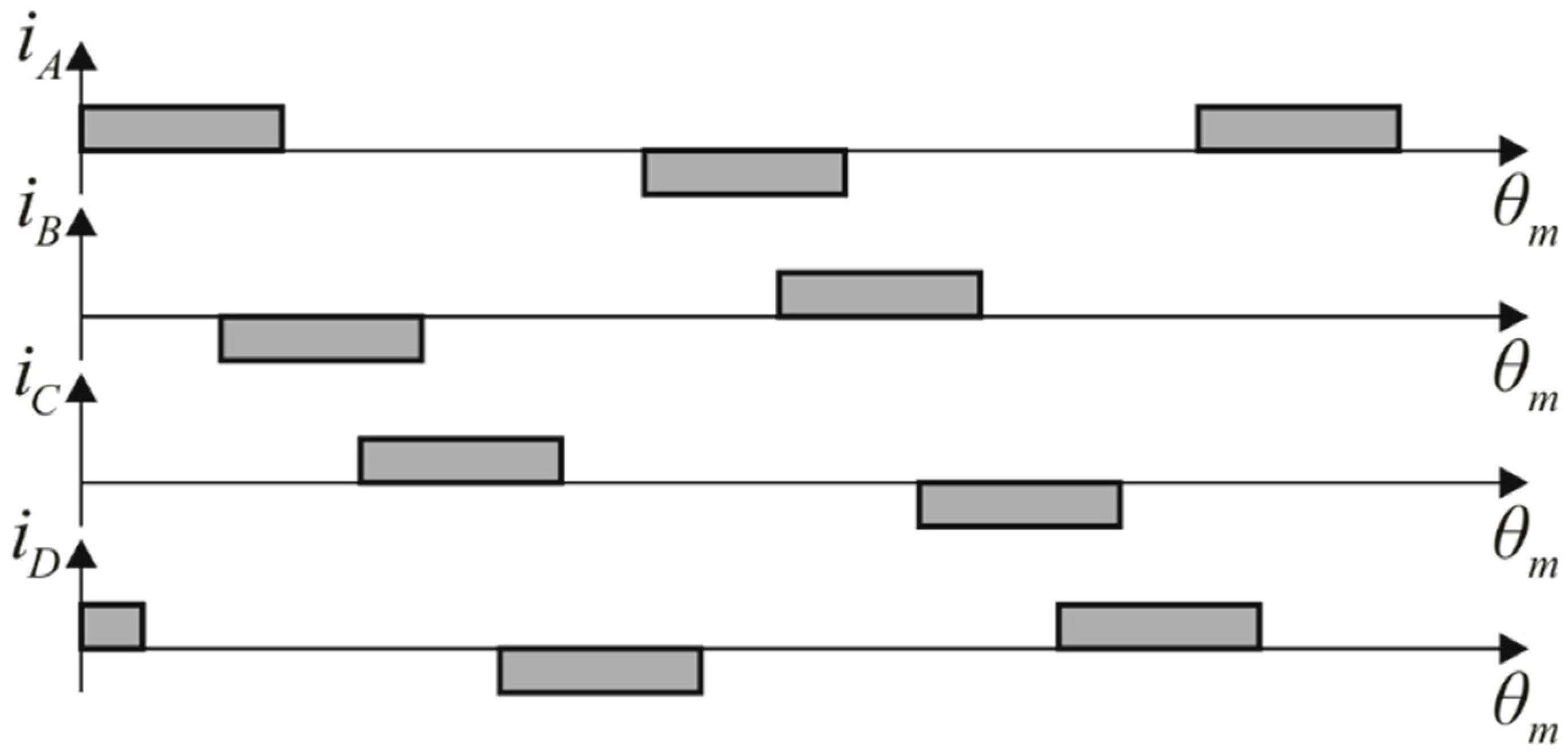
I4, which is possible if magnetic symmetry between phases exists. Magnetic symmetry can be achieved using industrial dual-pack modules (H-bridges) with the control algorithm [
22], which ensures four SFPEs over each electrical cycle. This type of supply results in bipolar phase currents. A converter topology that ensures magnetic symmetry in both the symmetrical and asymmetrical 8/6 SRM consists of four separate full-bridge (H-bridge) converters, one supplying each phase [
22]. The bipolar phase excitation [
22] corresponding to the coil directions shown in
Figure 1 and
Figure 2 for maintaining a SFPE within each electrical cycle of an 8/6 SRM is illustrated in
Figure 3.
When magnetic symmetry is ensured, the magnitudes of orthogonal phase currents are mutually equal. The condition (i) related to the equality of total converter VA demands of the asymmetrical and symmetrical designs can be formulated as
where
I13max_P,
I24max_P, and
Isymmax_P are the maximal phase current peaks of the asymmetrical and symmetrical 8/6 SRM, respectively, whereas
V13,
V24, and
V are the corresponding DC-link voltages. As all H-bridges are connected to the same DC-link, the DC-link voltages are mutually equal (
V13 =
V24 =
V), and (23) is reduced to
By introducing coefficients
c13 =
I13max_P/
Isymmax_P, and
c24 =
I24max_P/
Isymmax_P, the previous relationship can be reformulated as
3.2. Asymmetrical 8/6 SRM Drive Design and Control Optimization
The optimal 8/6 SRM design and control parameters need to be determined. To do so, the following steps are followed:
- (a)
Feasible combinations of stator pole widths (βS13, βS24) and numbers of turns (N13, N24) are defined according to conditions (4) and (20);
- (b)
Optimization is first performed for each of the selected
βS13/
βS24 combinations. The optimization variables are the numbers of turns
N13 and
N24 and the control parameters (reference phase currents and turn-on and turn-off angles). The optimization objective is to obtain the maximal torque while satisfying constraints (i)–(iv) defined in
Section 2. Optimization is performed over a wide speed range of 400–13,200 rpm;
- (c)
Optimization of control parameters is performed for selected βS13/βS24 and N13/N24 combinations from the previous step. Unlike the previous step, a fixed number of turns is now used over the entire speed range in each optimization run;
- (d)
A single combination of pole widths (βS13, βS24) and numbers of turns (N13, N24) is selected and declared optimal based on the shapes of the respective power-speed characteristics obtained in the previous step.
The optimization procedure requires that the ranges of optimization variables and all constraints are defined. The optimization variables are as follows:
Coefficients z13 and z24;
Coefficients c13 and c24;
Turn-on angles for each set of orthogonal phases (θON13, θON24);
Dwell angles for each set of orthogonal phases (θDWELL13, θDWELL24).
It should be noted that all of the listed variables are optimized only in the first stage (step (b)), when design and control optimization are conducted simultaneously. In the second stage (step (c)), only the control parameters (
θON13,
θON24,
θDWELL13,
θDWELL24) are optimized for a selected design obtained in step (b). Such an approach is required, as design parameters obviously cannot be modified during operation. On the other hand, the optimal set of control parameters for the selected design is determined only for a single operating point in step (b); therefore, control parameter optimization must be conducted for all other operating points. In this way, optimization in step (c) results in optimal driver performance using a specific 8/6 SRM design obtained in step (b). It should be noted that simultaneous optimization of design and control parameters in step (b) is necessary to determine optimal design parameters. A JADE (Joint Optimization Differential Evolution) algorithm [
26] is used for optimization of the design and control parameters. The algorithm implements a “current-to-
p-best” mutation strategy with self-adaptive values of mutation and crossover rates to ensure fast and reliable convergence. The optimization algorithm is based on randomly selecting values of optimization variables within defined ranges, each combination constituting one viable candidate solution. In each step of the optimization, the algorithm attempts to improve the candidate solutions by preserving, replacing, or modifying previous solutions based on their measure of quality.
The outline of the JADE algorithm is illustrated by the flowchart in
Figure 4. Some of the specifics regarding algorithm implementation in this paper should be emphasized:
The limit values of optimization variables are determined empirically to include all feasible design and control variants.
The population size NP is set to 40 in step (b) and to 24 in step (c).
The optimization is completed if the number of iterations is higher than 100 and the standard deviation of average torque (Tavg) is lower than 0.5 Nm. If this condition is never met, the optimization procedure is ended after 400 generations.
Individuals are ranked according to the obtained average torque Tavg. The optimization constraint is that RMS currents may not exceed predefined permissible values.
To avoid overburdening the text, only the application-specific aspects of the JADE algorithm have been addressed. For more details, particularly regarding the self-adaptation of algorithm control parameters, one should refer to [
26].
Coefficients
z13 and
z24 are corelated by (20), and
c13 and
c24 are corelated by (25). Therefore, there are a total of six independent optimization variables. Note that
z13 and
z24 are complex functions of the machine dimensions, number of turns, and RMS current, whereas
c13 and
c24 are proportional to maximal phase current peaks. The stator pole width combination is not an optimization variable, as it is selected prior to each optimization run. The minimal stator pole width is limited to 360°/
NS/
q = 15° due to starting requirements [
1], whereas the rotor pole width
βR needs to be greater or equal to the width of the stator poles. The stator pole spans must therefore be kept within ranges
βS13 = (15°,
βSsym) and
βS24 = (
βSsym,
βR) in the case of variant 1, and vice versa in the case of variant 2. The selected values of pole widths must also satisfy condition (4). On the other hand, considering relationship (20), the theoretical range for coefficient
z1 would be (0, 1). However, seeing as
N13 >
Nsym, and due to practical limitations, the actual range of
z1 is reduced to (0.5, 0.8). The range of
z24 is then automatically determined, as
z24 = 1 −
z13. For given (selected) values of
βS13,
βS24 and
z13,
z24, values of
x13 and
x24 are determined from (21) and (22), after which maximal RMS currents of orthogonal phase sets
I13 and
I24 are calculated from (17) and (18), respectively. Based on the RMS current values, coefficients
k13 and
k24 are obtained. The numbers of turns
N13 and
N24 are determined based on the known values of
k13 and
k24. Finally, the phase winding resistances
R13 and
R24 are calculated according to (14). Having determined all the aforementioned parameters, a feasible asymmetrical 8/6 SRM drive that satisfies constraints (ii)–(iv) is defined, i.e., a design with the same fill factor and ohmic losses as the original symmetrical 8/6 SRM. In each iteration,
NP asymmetrical designs are defined in the described way, constituting a population.
Once the asymmetrical 8/6 SRM design parameters are defined, the control parameters need to be assigned to each asymmetrical design within the population. The control parameters should ensure maximal available torque without RMS phase currents exceeding maximal permissible values
I13 and
I24. The control parameters include reference current and turn-on and turn-off angles for each set of orthogonal phase pairs. Control parameters for phases 1 and 3 are the reference current
Iref13, turn-on angle
θON13, and turn-off angle
θOFF13. The given angles refer specifically to phase 1 and should be shifted by 30° for phase 3. Similarly, the reference current and turn-on and turn-off angles of phases 2 and 4 are
Iref24,
θON24, and
θOFF24, respectively. The given angles refer to phase 2 and should be shifted by 30° for phase 4. If the reference angle is set so that the unaligned position of phase 1 equals 30°, the turn-on angle values are selected from ranges that depend on the stator and rotor pole widths as follows [
27]:
Note that the turn-off angles are defined as θOFF13 = θON13 + θDWELL13 and θOFF24 = θON24 + θDWELL24. The dwell angles for all phases are selected from the range (13°, 30°).
When setting the values of reference currents, the constant VA demand formulated by (25) must be fulfilled. The theoretical range of c13 is (0, 2), but it is narrowed down to (0.2, 1.8) due to practical considerations. By selecting the value of c13, we automatically obtain c24 = 2 − c13.
In order to carry out steps (b), (c), and (d), as well as the comparison of asymmetrical and symmetrical drive, it is necessary to determine the optimal control parameters of the symmetrical drive, turn-on angle (
θON), turn-off angle (
θOFF), and reference current (
Iref) for which the maximum output torque is achieved, and the RMS value of the phase current does not exceed the rated value
Isym =
Inom = 3.2 A, which is given in
Appendix A. To determine optimal control parameters of the symmetrical drive, model [
25] is used, which includes all substantial non-linearities and mutual coupling between phases. This model is also used for the design of the asymmetrical 8/6 SRM drive, i.e., the realization of steps (b) and (c). Though using a FEM model in the optimization process would yield slightly more accurate results, such an approach would be much more time-consuming compared to using model [
25]. On the other hand, it was previously shown that the results of model [
25] are in very good agreement with the results of the corresponding FEM model. Further validation of the applied model is provided in
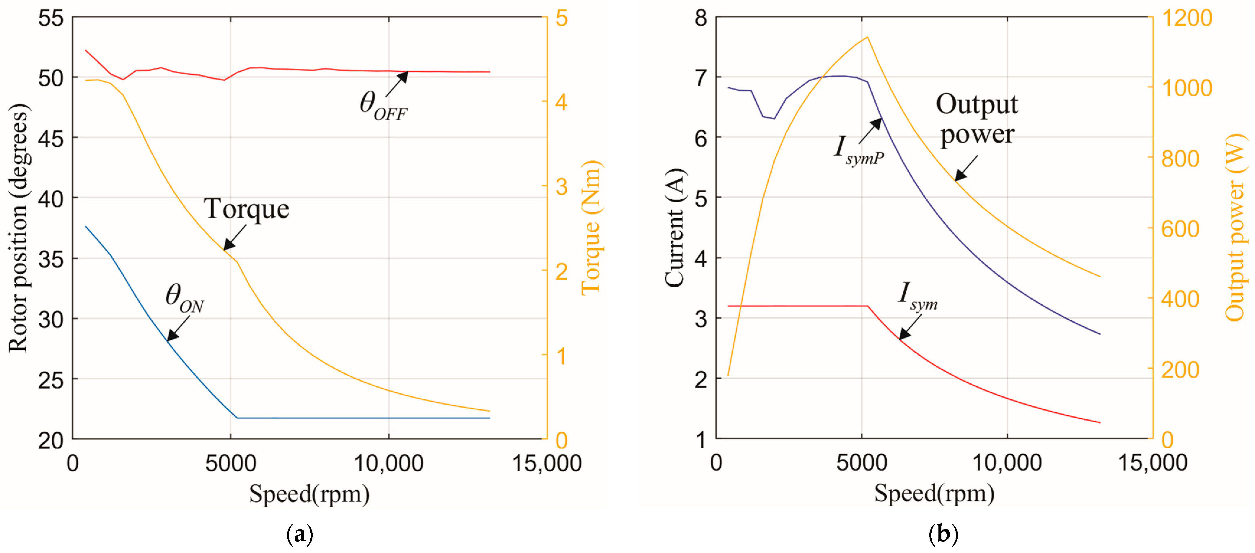
Section 6. The optimization of the control parameters of the symmetrical drive was performed for a speed range between 400 and 13,200 rpm with a step of 400 rpm.
The calculation results are shown in
Figure 5. The optimal control turn-on and turn-off angles together with developed torque are given in
Figure 5a, and the output power, RMS phase current (
Isym), and phase current peak value (
IsymP) are shown in
Figure 5b. From
Figure 5b, it can be seen that the maximum of
IsymP is
Isymmax_P = 7.01 A. Based on this value, the total VA requirements of the symmetrical drive are determined according to relationship (23) as 16
VIsymmax_P = 16 × 220 × 7.01 = 24.675 KVA.


