Article

Parameter Identification of Flexible Link Manipulators Using Evolutionary Algorithms

by
Fabian Andres Lara-Molina
Department of Mechanical Engineering, Federal University of Triângulo Mineiro, Uberaba 38025-180, MG, Brazil
Machines 2024, 12(6), 409; https://doi.org/10.3390/machines12060409
Submission received: 10 May 2024 / Revised: 2 June 2024 / Accepted: 11 June 2024 / Published: 14 June 2024
(This article belongs to the Special Issue Nonlinear Mechanical Vibration in Machine Design)

Abstract

:
This paper addresses the parameter identification of a one-link flexible manipulator based on the experimental measurement of the inputs/outputs, the finite element model, and the application of evolutionary algorithms. A novel approach is proposed to find the values of inertia, stiffness, and damping parameters by minimizing the difference between the numerical model’s outputs and the testbed’s outputs, thus considering the joint position and acceleration of the link’s tip. The dynamic model is initially obtained using the finite element method and the Lagrange principle. A prototype of a single one-link flexible manipulator is used in the experimental application, wherein the servomotor applies the input torque, and the outputs are the joint angle and the link’s tip acceleration. Then, an optimization problem minimizes the difference between the numerical and experimental outputs to determine the set of parameters using evolutionary algorithms. A comparative analysis to obtain the identified parameters is established using genetic algorithms, particle swarm optimization, and differential evolution. The proposed identification approach permitted the determination of the dynamic parameters based on the complete dynamic model of the flexible-link manipulator, which is different from the approaches reported in the literature that identify a simplified model. This information is essential for the design of the motion and vibration control laws.

1. Introduction

Flexible manipulators equipped with compliant structures have garnered significant interest due to their adaptability, dexterity, and safety features. Flexible manipulators have been applied to diverse application domains ranging from manufacturing and healthcare to space exploration and beyond, thus highlighting the versatility and potential impact of flexible manipulator technology. In manufacturing, flexible manipulators improve efficiency and accuracy in tasks such as assembly, pick-and-place operations, and quality inspection [1]. In healthcare, they enhance patient outcomes and reduce procedural risks in minimally invasive surgeries, rehabilitation therapies, and medical diagnostics [2]. Flexible manipulators also play integral roles in space exploration missions, thus enabling tasks such as satellite servicing, planetary exploration, and the maintenance of space infrastructure [3]. In addition, several research studies about flexible manipulator have been conducted to enhance their performance: these include modeling [4], optimization [5,6,7], and control [8].
In this context, several approaches have been proposed regarding the system identification of robotic manipulators for implementing control schemes that enhance the dynamic performance in the execution of the aforementioned applications [9]. Thus, system identification consists of a numerical and experimental procedure applied to estimate the physical parameters of a system and a mathematical model based on the system’s inputs and outputs [10]. Considering this, robotic manipulators with rigid link and transmissions different parameter identification methods have been applied, such as least squares, the extended Kalman filter, Adaptive Linear Neuron (Adaline) neural networks, Hopfield recurrent neural networks, and genetic algorithms [11].
Gray box model identification methods have widely been applied to flexible-link manipulators. Gray box model identification refers to methods that develop a mathematical model that combines known physical principles with empirical data-driven techniques; this approach is used for modeling systems that are partially understood, thus leading to simplified model systems being obtained [12]. The identification of a two-link flexible manipulator belonging to a class of multi-input, multi-output (MIMO) nonlinear systems was carried out by using adaptive time delay neural networks (ATDNNs) [13]. The identified model based on the modal responses of individual modes was evaluated; this approach allowed for obtaining the parameters of the modal model of a flexible-link manipulator [14]. The generalized orthonormal basis functions (GOBFs) were used for the model identification of flexible-link manipulators [15]. Moreover, The stiffness and damping ratio of a 3-TPT parallel manipulator with flexible links were identified using simulation and experimentation in [16]. An array of fundamental system identification procedures, which includes the ARX (AutoRegressive eXogenous method), SSEST (State Space Estimation method), N4SID (Numerical Algorithm for Subspace State Space System Identification), ERA/OKID (Eigensystem Realization Algorithm combined with the Observer/Kalman Filter Identification method), and TFEST (Transfer Function Estimation method) methods were applied to flexible-link manipulators [17]. In this direction, the model identification of single-link flexible manipulator was performed in [14,15,17], and the two-link flexible manipulator model identification was also considered in [13]. Thus, the approaches mentioned above were proposed to identify flexible manipulators to obtain a linear first-order and second-order linear mechanical system model; these approaches obtained nonparametric models that express the simplified linear dynamics of the flexible-link manipulators. Moreover, the vibrational dynamics of the flexible link were identified without taking into account the dynamics of the actuator [15,17].
However, the approaches mentioned above do not permit obtaining the dynamic parameters based on the complete model of the manipulation, i.e., these approaches updated the parameters of a simplified model that represents the flexible-link manipulator dynamics. Additionally, several research studies aimed at improving the modeling of flexible-link manipulators [8] to include the dynamics effects inherent to flexible-link manipulators such as uncertainties [18], modal characteristic [19], and nonlinear dynamic behavior [20]; this modeling approaches offers valuable information about the manipulator’s dynamics that can be considered to design optimization and the synthesis of control strategies of flexible-link manipulators. Consequently, it is necessary to develop identification approaches for flexible-link manipulators that permit the estimation of the nonlinear dynamic behavior based on the dynamic model without model simplifications.
Several approaches to identifying the parameters of flexible structures based on their input/output analysis and evolutionary algorithms have been successfully implemented. A modified genetic algorithm (GA) strategy was proposed to improve the accuracy and computational time for parameter identification of multiple-degree-of-freedom structural systems in [21]. A GA-based substructural identification strategy for large structural systems was conducted in [22] using an improved identification method based on a multi-feature GA. The inverse identification of elastic properties of composite materials was carried out using a hybrid GA-ACO-PSO algorithm in [23]. The structural parameter identification with evolutionary algorithms and correlation functions was carried out in [24]. A hybrid identification method in [25] was applied to structural health monitoring to detect the reduction of stiffness with limited sensors and contaminated measurements by applying evolutionary algorithms. The parameter identification of the sound absorption model of porous materials based on a modified particle swarm optimization algorithm was performed in [26]. Nevertheless, the approach mentioned above has not been applied to flexible manipulators.
In this context, the present contribution proposes an identification method that permit the identification of the physical parameters of flexible manipulators. The main contributions and improvements of the proposed identification method are (i) the identification of the dynamic parameters of the system based on the complete dynamic model that includes the flexible-link vibrational dynamics and the rotational dynamics of the actuator; (ii) considering the nonlinear dynamics such as the Coulomb frictions of the motor; and (iii) the estimation of all physical parameters of the model system; the existing approaches compute estimates of nonparametric models [14,15] or the parameters of simplified models [17]. Consequently, the present contribution proposed a parameter identification method to estimate the dynamic parameters of a flexible-link manipulator based on the complete model. Thus, the dynamic model is initially obtained using the finite element method and the Lagrange principle. Then, an optimization problem minimizes the difference between numerical and experimental outputs to determine the set of parameters using evolutionary algorithms. A comparative analysis to obtain the identified parameters is established using genetic algorithms, particle swarm optimization, and differential evolution. The proposed identification approach permitted the determination of the dynamic parameters based on the complete dynamic model of the flexible-link manipulator, which is different from the approaches reported in the literature that identify a simplified model.
The paper is organized into five sections. Section 2 presents the flexible-link manipulator modeling and the parameter identification approach. Section 3.2 shows the case study, wherein the proposed parameter identification approach is applied. Then, Section 4 presents the experimental results. Finally, Section 5 presents the conclusions and future work.

2. Materials and Methods

2.1. Flexible-Link Manipulator Dynamics

Several methods have been used to obtain the dynamic equation of flexible-link manipulators. These methods can be summarized into four main approaches: lumped-parameter system [27], Assumed Modes Method (AMM) [28,29], perturbation method [29], and Finite Element (FE) method [18,30]. The methods above lead to the dynamic equation of the flexible-link manipulator in the following form:
M q q ¨ + h q , q ˙ + C q ˙ + K q = f
where q is the vector of generalized coordinates, M ( q ) is the total inertia matrix, h ( q , q ˙ ) is the the Coriolis/centripetal vector, C is the total damping matrix, K is the total stiffness matrix, and f is the vector of generalized force/torque inputs. The control inputs correspond to the generalized force/torque τ applied by motors or actuators in the vector generalized force/torque f .
Differently from rigid body manipulator models, the flexibility of the links introduces additional generalized coordination to the model. Thus, the control inputs are less than the number of generalized coordinates.
The least squares methods have been widely applied to identify the parameters of rigid body manipulators [9,11]. However, the traditional method for parameter identification based on the least squares method widely applied to rigid body manipulators cannot be applied to flexible-link manipulators, since the identified parameters cannot express the control inputs as a linear combination of the parameters. Therefore, an alternative approach should be proposed to identify the parameters of flexible-link manipulators.

2.2. Parameter Identification Approach

Inverse problems are employed to estimate system parameters by examining experimental inputs/outputs to infer the characteristics or properties of a given system. This process involves working backward from the effects or outputs of a system to determine the underlying causes or parameters that govern its behavior. Mathematical models that describe the relationship between inputs and outputs are often formulated to estimate system parameters. These models are then inverted to obtain the best-fit parameters that align with the experimental outputs to the numerical model outputs [23,25].
The present approach aims at identifying the parameters of the flexible-link manipulator based on an inverse problem approach that adjusts the parameters of the model to minimize the differences between the experimental inputs/outputs of the manipulator and the numerical model of Section 2.1. As an innovative contribution, the present approach permits (i) white box identification of the dynamic parameters of the system based on the complete dynamic model based on the finite element method and the Lagrange principles and (ii) consideration of the nonlinear dynamics such as the Coulomb frictions of the motor.
The proposed approach is presented in the diagram of Figure 1. This approach is composed of two main steps: experimental measurements of the flexible-link manipulator inputs/outputs and numerical procedure.
Initially, the actuator’s inputs and the generalized coordinate’s outputs are measured. For this approach, the inputs correspond to the actuator torques ( τ 1 ), and the outputs correspond to joint angles ( ϕ e ) and the acceleration at the tip of the link. The dynamic behavior of the flexible-link manipulator encompasses the joint motion and the vibration of the flexible link. For this purpose, two different inputs should be considered for the actuator torque: (a) a pulse input to mainly excite the flexible-link dynamics and (b) a step input to excite the joint dynamics. Moreover, the measurement outputs of the generalized coordinates are the joint actuator of the actuator ( ϕ e ) and the link’s tip acceleration ( u ¨ e ).
Then, there is the numerical procedure to minimize the difference between the numerical model outputs ( u ¨ e and ϕ e ) and the measurement outputs of the prototype by fitting the parameters to be identified within the numerical model. The numerical model is computed by integrating the dynamic equation of flexible-link manipulator in Equation (1); for this procedure, the inputs are the motor torque τ 1 and the vector of the parameter to be identified p ^ (see Figure 1). The numerical model outputs u ¨ n and ϕ n correspond to the link’s tip acceleration and joint angle, respectively. Moreover, the Frequency Response Function ( F R F ) is obtained to evaluate the vibratory dynamics of the flexible link by applying the pulse torque and measuring the link’s tip acceleration. The minimization of the output difference between the experimental measurements and numerical model outputs derives from an optimization problem that aims at minimizing the objective function J ( p ^ ) .
min p ^ ( p ^ l , p ^ r ) J ( p ^ )
where p ^ is the identified parameters vector, and the objective function is defined as J ( p ^ ) = | | F R F e F R F n ( p ^ ) | | + | | ϕ e ϕ n ( p ^ ) | | .
The optimization problem of Equation (2) can be solved by using evolutionary algorithms such as genetic algorithms (GAs), differential evolution (DE), and particle swarm optimization (PSO).

3. Case Study: One-Link Flexible Manipulator

3.1. Testbed

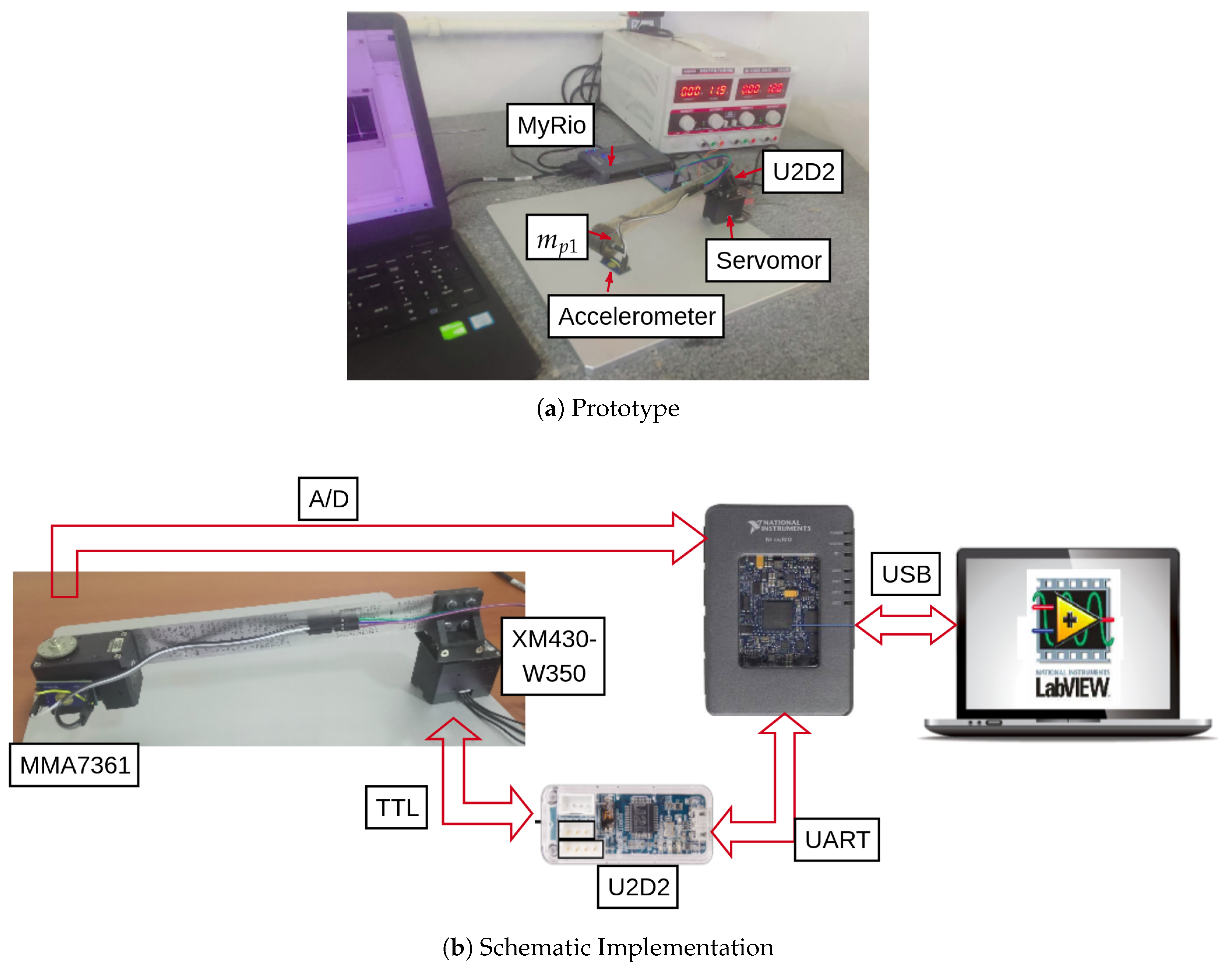
Figure 2a shows the prototype of the one-link flexible manipulator used in the experimental application. The servomotor applies the input torque ( τ 1 ). The outputs are the joint angle ( ϕ ) and the link’s tip acceleration ( u ¨ 4 ), which are measured by the servomotor encoder and the tip’s link accelerometer, respectively. These inputs and output will make it possible to compute objective function J ( p ^ ) that will consider the joint angle ϕ and the F R F between the tip’s acceleration ( u ¨ 4 ) and the torque input ( τ 1 ) according to Equation (2).
The following geometrical and mass parameters of the prototype were directly measured. The link length was defined as l 1 = 0.197 m. The link cross-section area A was defined as a rectangle with dimensions h = 0.001 m by b = 0.0266 m; thus, A = b h , and the moment of inertia of the cross-section area is I = b h 3 / 12 . Moreover, the mass density was ρ = 6404.3 kg/m3, and the payload mass was m p 1 = 0.09466 kg. The Euler beam theory can be applied to model the manipulator’s link, because it is a slender (long and thin) beam [31]. For this model, the accelerometer MMA7361 was attached to payload mass, and its moment of inertia was negligible.
Figure 2b shows the schematic diagram of the flexible manipulator’s instrumentation, data acquisition, and actuation. The NI myRIO board controls the XM430-W350 Dynamixel servomotor, and the U2D2 interface couples the servomotor and the NI myRIO board. The accelerometer MMA7361 is connected to the input of the A/D (Analog-to-Digital Converter). The programs of NI myRIO were coded using LabVIEW®.

3.2. Numerical Model

The schematic model of the one-link flexible manipulator is presented in Figure 3. The manipulator has one revolute joint defined by the angle ϕ 1 . The moment of inertia of the actuator hub is defined as I m 1 and considers the moment of inertia of the rotor motor and the hub that join the motor to the flexible link, and the flexible link with length l 1 and Young modulus E is attached to the actuator hub. Moreover, a payload mass m p 1 is attached at the link’s tip. Initially, the flexible link is split into four Euler–Bernoulli beam elements, as presented in Figure 3.
The finite element model was applied to obtain the dynamic equation of the manipulator according to the procedure presented in [18,30]. Thus, the dynamic equation is presented in Equation (3).
M 1 ( q 1 ) q ¨ 1 + h 1 ( q 1 , q ˙ 1 ) + C 1 q ˙ 1 + K 1 q 1 + f b = f 1
where f 1 = τ 1 0 0 0 0 0 0 0 means that the input torque τ 1 of the motor is applied only on the joint ϕ 1 . The generalized coordinates are defined as q 1 = ϕ 1 ψ 1 , with ψ 1 being generalized coordinates of the link ψ 1 = u 1 θ 1 u 2 θ 2 u 3 θ 3 u 4 θ 4 . Moreover, M 1 ( q ) is the total inertia matrix, h 1 ( q 1 , q ˙ 1 ) is the Coriolis/centripetal vector, and K 1 is the total stiffness matrix. The motor applies the input torque τ 1 ; the outputs considered in the model are the joint angle of the motor ϕ and the link’s tip acceleration defined as u ¨ n = l 1 ϕ ¨ 1 + u ¨ 4 .
The mass matrix and the total stiffness matrix of Equation (3) can be written in the following form:
M 1 ( q 1 ) = m ϕ 1 ϕ 1 m ϕ 1 ψ 1 m ψ 1 ϕ 1 M ψ 1 ψ 1 K 1 = 0 0 0 K ψ 1 ψ 1
where M ψ 1 ψ 1 is related to the transverse displacements or the elastic degrees of freedom of the links that correspond to ψ 1 ; m ϕ 1 ψ 1 indicates the coupling between the joint ϕ 1 and these elastic degrees of freedom ψ 1 , and m ψ 1 ϕ 1 = m ϕ 1 ψ 1 ; m ϕ 1 ϕ 1 takes into account the dynamics of the joint. Moreover, K ψ 1 ψ 1 of the total stiffness matrix is the elementary stiffness matrix of the link; the total stiffness matrix does not have a coupling between the joint motion and the elastic degrees of freedom.
C 1 of Equation (3) is the damping matrix, which is based on the Rayleigh damping formulation with C 1 = α M ψ 1 ψ 1 + β K ψ 1 ψ 1 , where α and β are constants of proportionality.
Moreover, f b considers the viscous friction and Coulomb friction of the motor; thus, we have the following:
f b = v ϕ ˙ + τ c s g n ( ϕ ˙ ) 0 0 0 0 0 0 0
where v is the viscous friction coefficient, τ c is the Coulomb torque, and s g n ( . ) refers to the sign function.
The inertia, joint friction, stiffness, and damping parameters significantly influence the manipulator dynamics. Nevertheless, these parameters cannot be measured experimentally. Therefore, the parameters to be identified in the flexible-link manipulator model are set in the vector p ^ = E ^ I m ^ v ^ τ c ^ α ^ β ^ .

4. Results and Discussion

The parameter identification process based on the flexible-link manipulator dynamics model was carried out according to the method of Section 2.2. The parameters to be identified are set in vector p ^ = E ^ I m ^ v ^ τ c ^ α ^ β ^ . The computation of the objective function J ( p ^ ) demands to compute the numerical model of the one flexible-link manipulator based on Equation (3) that depends on the parameters to be identified p ^ . The objective function J ( p ^ ) to be minimized is defined as the difference between the outputs of the numerical model and those measured experimentally in the flexible-link manipulator prototype. Thus, the objective function J ( p ^ ) considers the frequency domain response that takes into account the vibrational dynamics of the flexible link and the time domain response of the motor angle ϕ , as presented in Equation (6).
J ( p ^ ) = F R F e F R F n ( p ^ ) F R F e + ϕ e ϕ n ( p ^ ) ϕ e
The experimental frequency response functions F R F e (toque input/link’s tip acceleration) were measured on the flexible manipulator by applying a pulse torque input τ 1 at the motor and the link’s tip acceleration; the response output of the acceleration at the tip u ¨ e is in a range of 0–50 Hz and steps of 0.2 Hz.
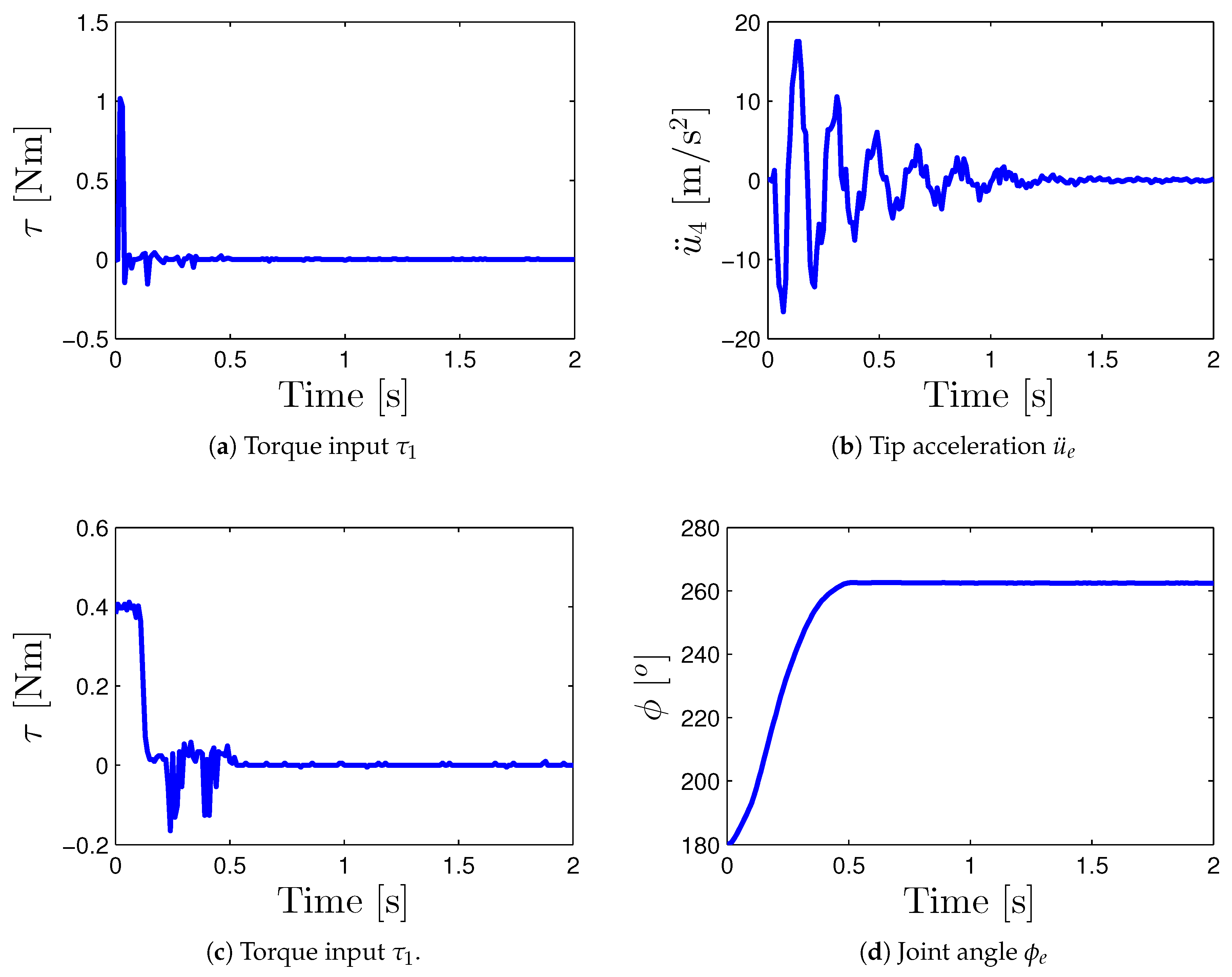
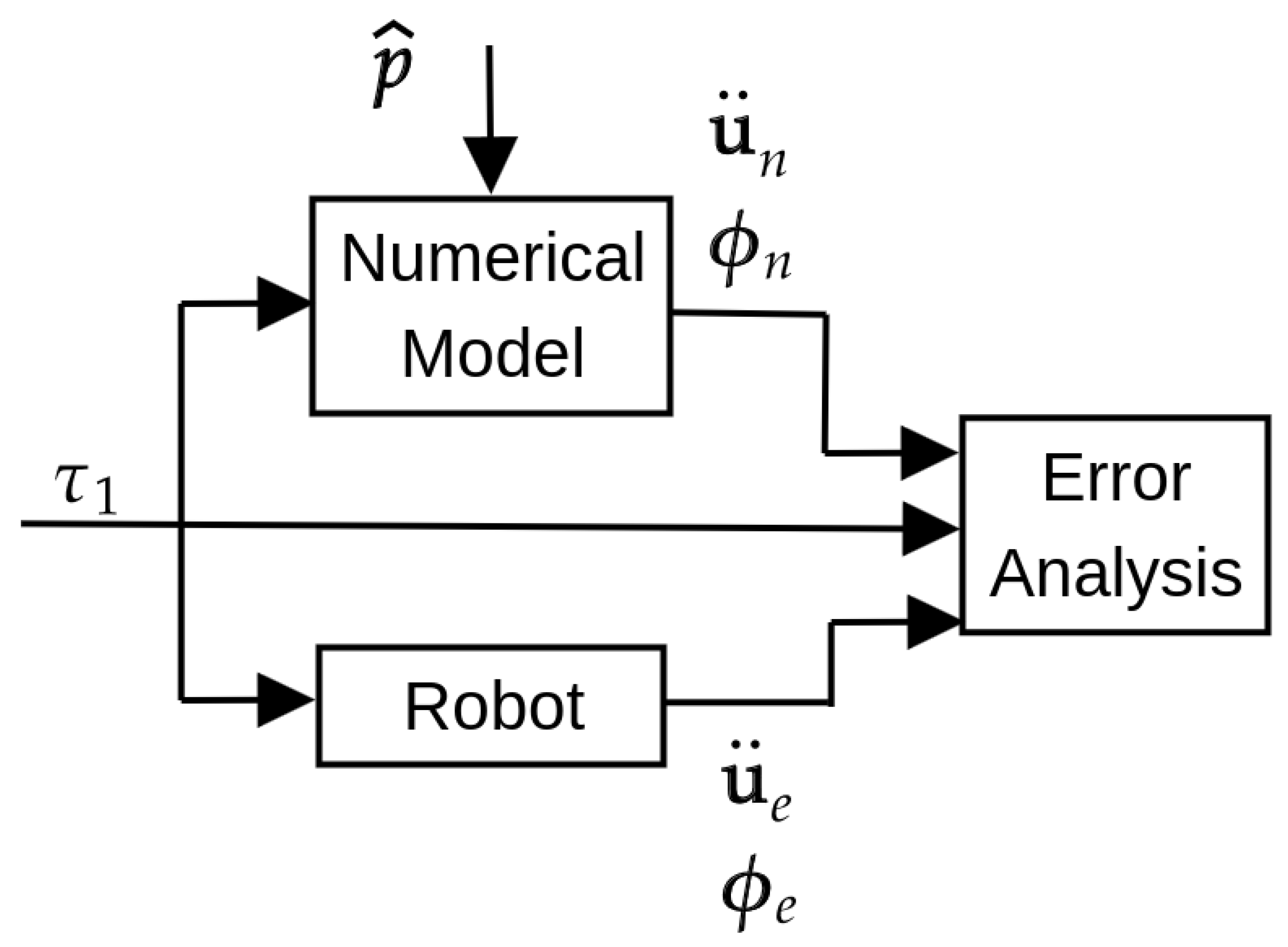
The experimental procedures described in Figure 1 consist of measuring the experimental inputs and outputs necessary to compute the objective function J ( p ^ ) of Equation (6) (see Figure 4). The short time pulse torque of Figure 4a was considered as an input to excite the vibratory dynamics of the flexible link; thus the link’s tip acceleration of Figure 4b is measured as an output; thus, the F R F e of link’s tip acceleration ( u ¨ e )/pulse torque ( τ 1 ) is obtained. Then, the input torque τ 1 of Figure 4c is applied to obtain the joint angle ϕ e of Figure 4d.
The identified parameters are obtained by solving the optimization problem of Equation (2). Table 1 shows the set of lower ( p ^ l ) and upper bounds ( p ^ r ) on the design variables that correspond to the identified parameters; thus, p ^ ( p ^ l , p ^ r ) .
This optimization problem is solved by using differential evolution (DE), the genetic algorithm (GA), and particle swarm optimization (PSO). The configurations and settings of the evolutionary algorithms (GA, PSO, and DE) were set based on the literature and previous results to make a fair definition of computational time and computational resources. For PSO, the parameters were suggested by [32]. For the case of the GA and DE, the parameters were set based on previous experience in solving similar problems [33,34]. Some assumptions were defined regarding the numerical application of the evolutionary algorithms:
  • The parameters used by the DE algorithm [35] are the following: population size N P = 100, weighting factor F = 0.5, crossover probability C R = 0.8, 100 generations, and D E / r a n d / 1 / e x p strategy for the generation of candidates.
  • The parameters used by the GA algorithm [36] are the following: N P = 100, selection rate S R = 0.5, crossover rate C R = 0.8, mutation rate M R = 0.2, and 100 generations.
  • The parameters used by the PSO algorithm [32] are the following: number of particles N P = 100, inertia weigth w = 1.4, c 1 = 1.5, c 2 = 2.5, and 100 iterations.
  • The stopping criteria considered was the maximum number of generations/iterations.
  • The study cases were run 10 times, and the average values were obtained.
  • To establish a fair comparison among the evolutionary algorithms, the seeds 0, 1, 2, …, 9 were used to initialize the random generator for each simulation.
  • The aforementioned case studies, using DE, the GA, and PSO, were run 10 times to obtain the upcoming average values.
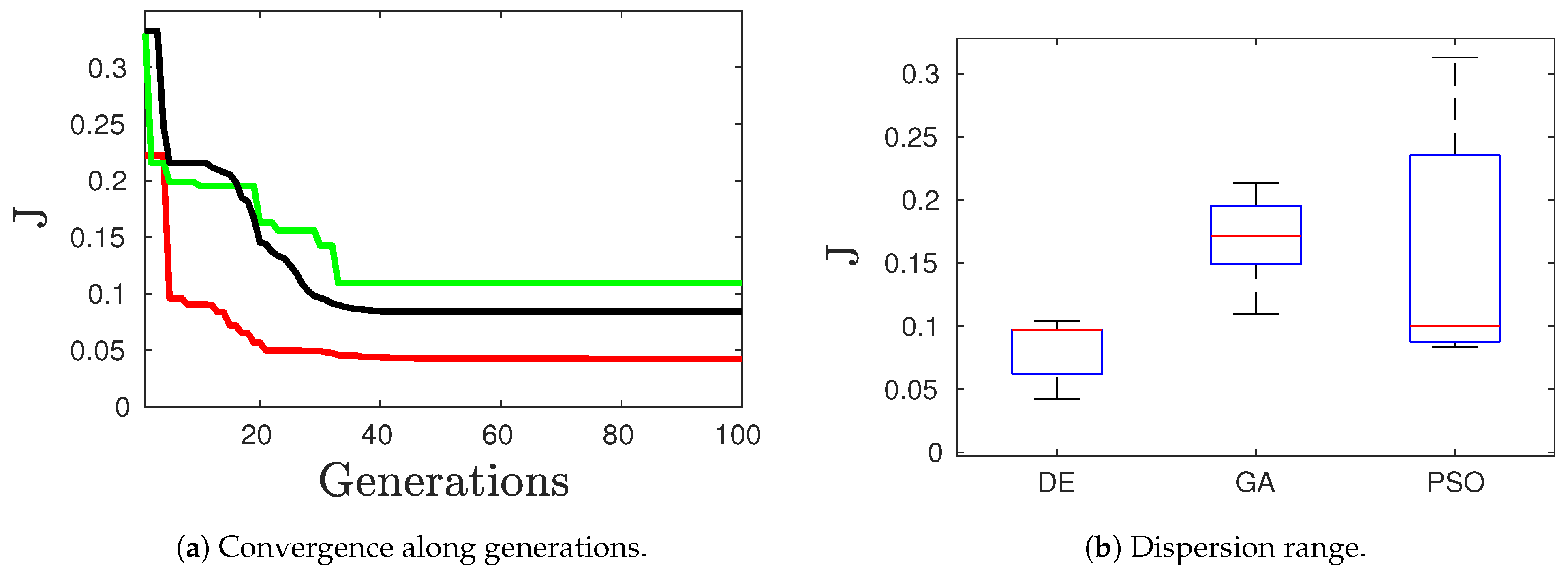
Figure 5 shows the convergence of the objective function J ( p ^ ) of Equation (6) during the optimization process solution considering the best solution for DE, the GA and PSO. Figure 5a exhibits the best individual of the population along the generations. One can observe that the DE algorithm exhibited the best performance, because it obtained the minimum value of J ( p ^ ) at the twelfth generation. The GA algorithm presented the worst behavior for solving the optimization problem.
For comparison purposes, the dispersion range obtained by minimizing the objective function J ( p ^ ) of Equation (6) 10 times considering the evolutionary algorithms is presented in Figure 5b. The PSO algorithm presented the highest dispersion of the results; nevertheless, the GA obtained the highest mean, thus indicating that the solution of the optimization problem using the GA is inaccurate in the present application. On the other hand, DE presented the lowest mean and dispersion.
Table 2 shows the best result of Figure 5a obtained using evolutionary algorithms. One can observe that the results found using the considered evolutionary algorithms are similar. It is worth pointing out that the joint friction and damping coefficients identified showed an expressive difference. These results are expected, because the model has three types of energy dissipation: joint friction (viscous and Coulomb friction) and the proportional damping of the flexible link.
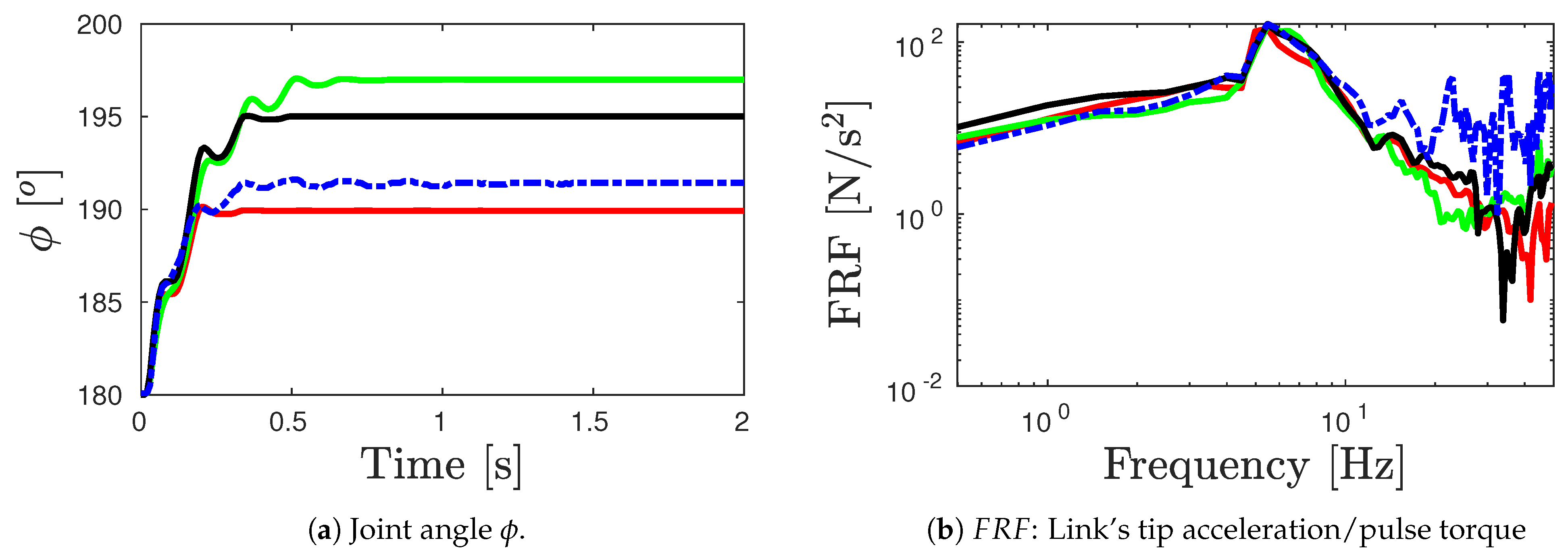
Figure 6 shows the dynamic response obtained from the DE, GA, and PSO algorithms. These results considered the joint angle ϕ and the F R F that were used in the objective function J ( p ^ ) . These results consider the F R F (see Figure 6b, which was obtained by applying a pulse torque input in the motor) and the joint angle ϕ ( t ) (see Figure 6a). As expected, the solution of the numerical model using the identified parameters obtained with DE is close to the experimental results (see Figure 6a). In addition, the F R F obtained with the numerical model considering the identified parameters are satisfactory (see Figure 6b) and close to the peak; nevertheless, expressive differences can be observed for high frequencies.
A comparison study with previous approaches could be conducted. Nevertheless, this study would present an unfair comparison of our proposed parameter identification method to a time domain model identification approach that conveys nonparametric and simplified linear models. The techniques presented in the literature were used to obtain first-order and second-order mechanical models of the flexible manipulator by using the ARX, SSEST, N4SID, ERA/OKID, and TFEST methods [17].

Model Validation

The model validation aims at evaluating confidence in the estimated robot model by comparing the numerical model outputs to the experimental outputs. The model validation approach is presented in Figure 7. A test input τ 1 was applied to the flexible robot prototype (of Figure 7) to obtain the experimental outputs u ¨ e and ϕ e . In this procedure, the same test input τ 1 was applied to the numerical model considering the identified parameters p ^ to obtain the numerical outputs u ¨ n and ϕ n . Table 3 shows the mean and standard deviation of the identified parameters p ^ using DE of the outcomes obtained from the ten times that DE was run.
Finally, an error analysis assessed the differences between the numerical and experimental outputs.
The model validation of the proposed identification approach was carried out, and the following results were obtained:
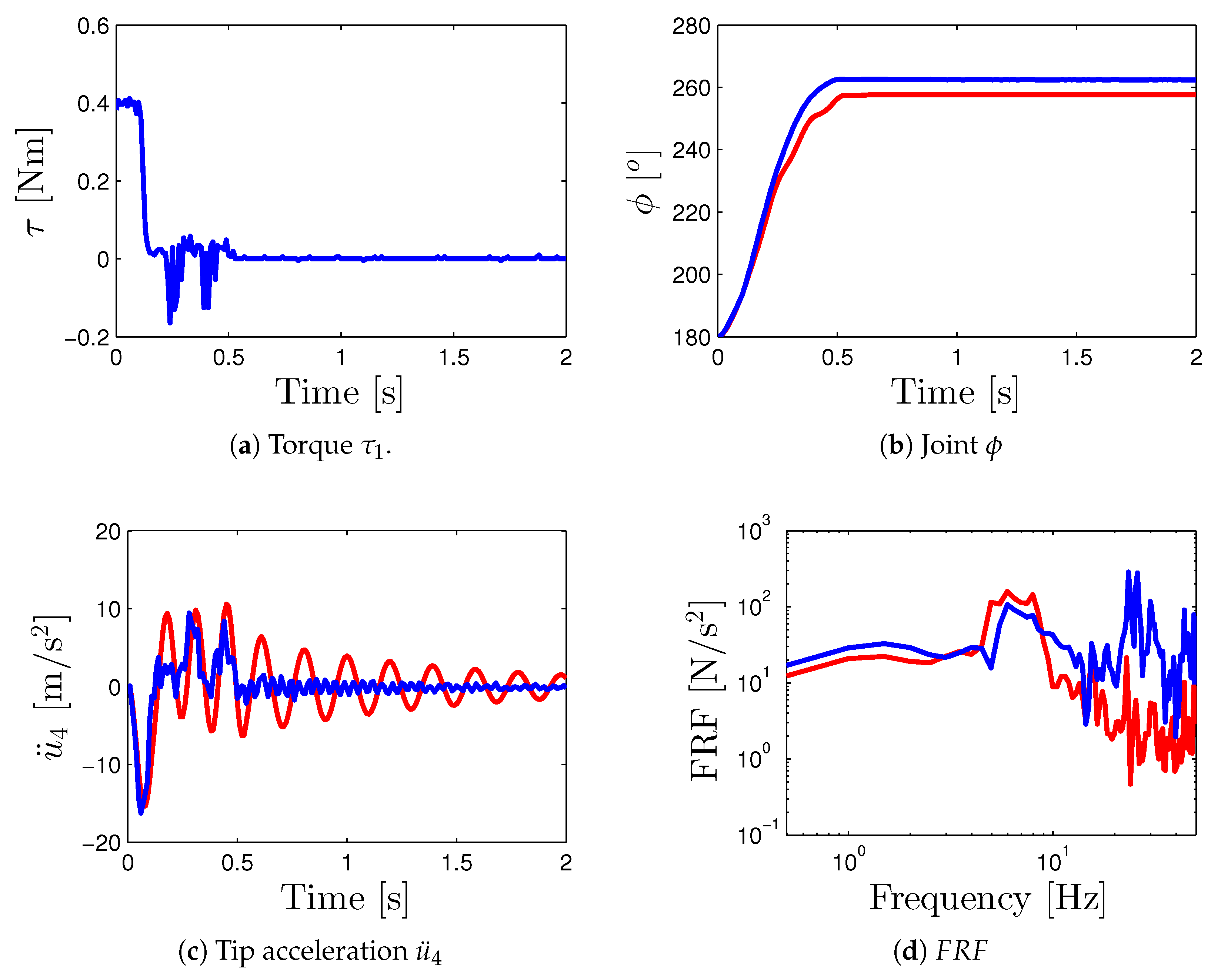
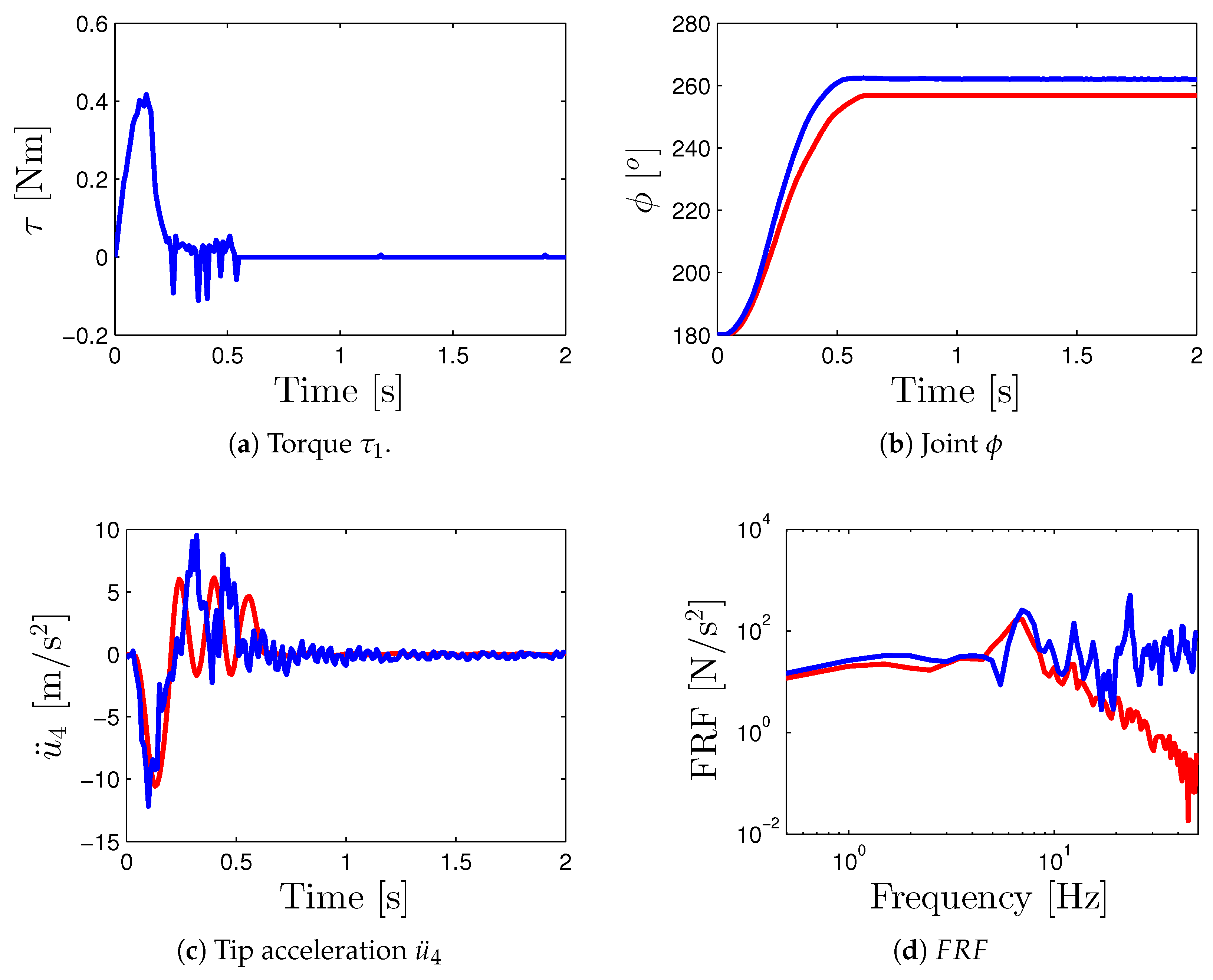
  • Three different test inputs were considered for the torque applied by the servomotor that permits assessment of the numerical and experimental dynamic response: triangular (see Figure 8a), pulse (see Figure 9a), and sinusoidal that considers the positive part (see Figure 10a). These inputs are three different signal profiles of torque that produce different angular accelerations at the flexible link. These torques were applied from 0 (seg) to 0.3 (seg) to move the joint angle ϕ to a maximum angular displacement of 80 (deg). Figure 8a, Figure 9a and Figure 10a show the torque applied torque that was measured using the current sensor of the servomotor.
  • The identified parameters p ^ considered in the numerical model were obtained from the best case of DE, and these parameters are presented in Table 2.
  • The numerical and experimental outputs of the joint angle ϕ for the corresponding test inputs are presented in Figure 8b, Figure 9b and Figure 10b.
  • The numerical and experimental outputs of link’s tip acceleration u ¨ for the corresponding test inputs are presented in Figure 8c, Figure 9c and Figure 10c. Moreover, the frequency response functions (toque input/link’s tip acceleration) for the numerical and experimental outputs are also computed in Figure 8d, Figure 9d and Figure 10d.
  • For the error analysis, the error between the numerical model and experimental outputs in terms of the joint angle ϕ and the F R F s were estimated based on the Normalized Root Mean Square Error ( R M S E ) according to the expressions of Equation (7).
N R M S E ϕ = t = 0 T ( ϕ e ( t ) ϕ n ( t ) ) 2 ϕ e ( t ) ¯ N R M S E F R F = f = 0 F ( F R F e ( f ) F R F n ( f ) ) 2 F R F e ( f ) ¯
where T = 2 s and F = 15 Hz. The Root Mean Square (RMS) outputs are presented in Table 4.
The results of the model validation show that the numerical model adequately represents the dynamic behavior of the flexible-link manipulator according to the results of Figure 8, Figure 9 and Figure 10. Moreover, the normalized R M S E s of Table 4 show that the percentage error between the numerical and experimental output is less acceptable for the present application. However, the numerical F R F does not have an acceptable representation for high frequencies due to the noise introduced by the accelerometer during the experiment.
A slight difference between the numerical and experimental outputs is observed in the validation approach according to the error Root Mean Squares Error of Equation (7). On the one hand, one can observe the steady state error between the numerical joint angle ϕ n and the experimental joint angle ϕ e in Figure 8b, Figure 9b and Figure 10b due to minor errors and neglected dynamics associated mainly with the friction parameters of joints v and τ c ; these parameters have a significant influence in the joint dynamics. On the other hand, a slight difference between the numerical and experimental outputs of the link’s tip acceleration is observed in Figure 8c, Figure 9c and Figure 10c; the effect of this noise in the accelerometer mainly impacted the F R F high frequencies.
The measurement errors of acceleration can be attenuated by substituting the low-cost MMA7361 accelerometer with a high-performance accelerometer. Moreover, the torque control for the input torque of the Dynamixel servomotors was inaccurate and affected by friction and backlash; a servomotor with a high-performance torque control could reduce the errors.

5. Conclusions

The present contribution presented a novel approach to identifying the dynamic parameters of flexible-link manipulators, such as inertia, stiffness, and damping parameters, based on the inverse problem associated with the parameter identification problem. The proposed approach minimized the difference between the numerical model’s outputs and the experimental measurements of the prototype. Then, an optimization problem that minimizes the difference between numerical and experimental outputs was used to determine the dynamic parameters. This optimization was solved using genetic algorithms, particle swarm optimization, and differential evolution. The proposed identification approach permitted the determination of the dynamic parameters based on the complete dynamic model of a one-link flexible manipulator.
The DE algorithm was demonstrated to be the most appropriate algorithm to solve the optimization associated with the identification approach compared to the PSO and GA algorithms. The proposed methodology permitted the estimation of the joint friction, stiffness, and damping coefficients of the flexible link that experimental measurements could not determine. Additionally, the numerical model with the identified parameters adequately simulated the dynamics regarding the joint response and the vibrational flexible-link dynamics of the manipulator, as demonstrated in the model validation approach.
Finally, the results show that the approach represents an alternative method to identify the dynamic parameters of flexible-link manipulators. Further research will aim to develop and improve model-based control schemes of flexible-link manipulators such as computed torque control, adaptive control, and sliding mode control. Moreover, statistical analyses to assess the robustness using sensitivity analysis or Monte Carlo simulation to evaluate the impact of input parameter variations will be carried out in future work.

Funding

This research received no external funding.

Data Availability Statement

The data are contained within the article.

Acknowledgments

The author is thankful for the technical support of Fabio Adan Lara Ordoñez and German Hincapie Navarrete through the Escuela Aeronautica de Colombia.

Conflicts of Interest

The author declares no conflicts of interest.

References

  1. Cordier, J.; Friconneau, J.; Gargiulo, L.; Grisolia, C.; Palmer, J.; Perrot, Y.; Samaille, F. Articulated inspection arm for ITER, a demonstration in the Tore Supra tokamak. In Proceedings of the 20th IEEE/NPSS Symposium on Fusion Engineering, San Diego, CA, USA, 14–17 October 2003; IEEE: Piscataway, NJ, USA, 2003; pp. 197–200. [Google Scholar]
  2. Zhang, Y.; Lu, M. A review of recent advancements in soft and flexible robots for medical applications. Int. J. Med. Robot. Comput. Assist. Surg. 2020, 16, e2096. [Google Scholar] [CrossRef]
  3. Sąsiadek, J. Space robotics and its challenges. In Aerospace Robotics: Selected Papers from I Conference on Robotics in Aeronautics and Astronautics; Springer: Berlin/Heidelberg, Germany, 2013; pp. 1–8. [Google Scholar]
  4. Li, B.; Li, X.; Gao, H.; Wang, F.Y. Advances in Flexible Robotic Manipulator Systems—Part I: Overview and Dynamics Modeling Methods. IEEE/ASME Trans. Mechatron. 2024, 29, 1100–1110. [Google Scholar] [CrossRef]
  5. Lara-Molina, F.A.; Gonçalves, R.S. Reliability-based optimization of flexible manipulators. J. Vib. Eng. Technol. 2023, 11, 3147–3162. [Google Scholar] [CrossRef]
  6. Lismonde, A.; Sonneville, V.; Brüls, O. A geometric optimization method for the trajectory planning of flexible manipulators. Multibody Syst. Dyn. 2019, 47, 347–362. [Google Scholar] [CrossRef]
  7. Lara-Molina, F.A.; Dumur, D.; Assolari Takano, K. Multi-objective optimal design of flexible-joint parallel robot. Eng. Comput. 2018, 35, 2775–2801. [Google Scholar] [CrossRef]
  8. Sayahkarajy, M.; Mohamed, Z.; Mohd Faudzi, A.A. Review of modelling and control of flexible-link manipulators. Proc. Inst. Mech. Eng. Part I J. Syst. Control Eng. 2016, 230, 861–873. [Google Scholar] [CrossRef]
  9. Wu, J.; Wang, J.; You, Z. An overview of dynamic parameter identification of robots. Robot. Comput.-Integr. Manuf. 2010, 26, 414–419. [Google Scholar] [CrossRef]
  10. Cammarata, A.; Sinatra, R.; Rigano, A.; Lombardo, M.; Maddio, P.D. Design of a large deployable reflector opening system. Machines 2020, 8, 7. [Google Scholar] [CrossRef]
  11. Urrea, C.; Pascal, J. Design, simulation, comparison and evaluation of parameter identification methods for an industrial robot. Comput. Electr. Eng. 2018, 67, 791–806. [Google Scholar] [CrossRef]
  12. Pires, I.; Ayala, H.V.H.; Weber, H.I. Nonlinear ensemble gray and black-box system identification of friction induced vibrations in slender rotating structures. Mech. Syst. Signal Process. 2023, 186, 109815. [Google Scholar] [CrossRef]
  13. Yazdizadeh, A.; Khorasani, K.; Patel, R.V. Identification of a two-link flexible manipulator using adaptive time delay neural networks. IEEE Trans. Syst. Man Cybern. Part B (Cybern.) 2000, 30, 165–172. [Google Scholar] [CrossRef] [PubMed]
  14. Liu, K.; Sun, X. System identification and model reduction for a single-link flexible manipulator. J. Sound Vib. 2001, 242, 867–891. [Google Scholar] [CrossRef]
  15. Ziaei, K.; Wang, D.W. Application of orthonormal basis functions for identification of flexible-link manipulators. Control Eng. Pract. 2006, 14, 99–106. [Google Scholar] [CrossRef]
  16. Zhu, C.; Wang, J.; Chen, Z.; Liu, B. Dynamic characteristic parameters identification analysis of a parallel manipulator with flexible links. J. Mech. Sci. Technol. 2014, 28, 4833–4840. [Google Scholar] [CrossRef]
  17. Pappalardo, C.M.; Lök, Ş.İ.; Malgaca, L.; Guida, D. Experimental modal analysis of a single-link flexible robotic manipulator with curved geometry using applied system identification methods. Mech. Syst. Signal Process. 2023, 200, 110629. [Google Scholar] [CrossRef]
  18. Lara-Molina, F.A. Modeling of Flexible-Link Manipulators Under Uncertain Parameters Based on Stochastic Finite Element Method. J. Mech. Robot. 2022, 14, 061002. [Google Scholar] [CrossRef]
  19. Meng, D.; She, Y.; Xu, W.; Lu, W.; Liang, B. Dynamic modeling and vibration characteristics analysis of flexible-link and flexible-joint space manipulator. Multibody Syst. Dyn. 2018, 43, 321–347. [Google Scholar] [CrossRef]
  20. Mehrjooee, O.; Fathollahi Dehkordi, S.; Habibnejad Korayem, M. Dynamic modeling and extended bifurcation analysis of flexible-link manipulator. Mech. Based Des. Struct. Mach. 2020, 48, 87–110. [Google Scholar] [CrossRef]
  21. Perry, M.; Koh, C.; Choo, Y. Modified genetic algorithm strategy for structural identification. Comput. Struct. 2006, 84, 529–540. [Google Scholar] [CrossRef]
  22. Trinh, T.N.; Koh, C.G. An improved substructural identification strategy for large structural systems. Struct. Control Health Monit. 2012, 19, 686–700. [Google Scholar] [CrossRef]
  23. Tam, J.H.; Ong, Z.C.; Ismail, Z.; Ang, B.C.; Khoo, S.Y.; Li, W.L. Inverse identification of elastic properties of composite materials using hybrid GA-ACO-PSO algorithm. Inverse Probl. Sci. Eng. 2018, 26, 1432–1463. [Google Scholar] [CrossRef]
  24. Wang, X.; Zhang, G.; Wang, X.; Ni, P. Output-only structural parameter identification with evolutionary algorithms and correlation functions. Smart Mater. Struct. 2020, 29, 035018. [Google Scholar] [CrossRef]
  25. Zhou, H.; Zhang, G.; Wang, X.; Ni, P.; Zhang, J. A hybrid identification method on butterfly optimization and differential evolution algorithm. Smart Struct. Syst. Int. J. 2020, 26, 345–360. [Google Scholar]
  26. Xu, X.; Lin, P. Parameter identification of sound absorption model of porous materials based on modified particle swarm optimization algorithm. PLoS ONE 2021, 16, e0250950. [Google Scholar] [CrossRef] [PubMed]
  27. Yoshikawa, T.; Hosoda, K. Modeling of flexible manipulators using virtual rigid links and passive joints. Int. J. Robot. Res. 1996, 15, 290–299. [Google Scholar] [CrossRef]
  28. Theodore, R.J.; Ghosal, A. Comparison of the assumed modes and finite element models for flexible multilink manipulators. Int. J. Robot. Res. 1995, 14, 91–111. [Google Scholar] [CrossRef]
  29. Jonker, J.B.; Aarts, R.G. A perturbation method for dynamic analysis and simulation of flexible manipulators. Multibody Syst. Dyn. 2001, 6, 245–266. [Google Scholar] [CrossRef]
  30. Usoro, P.B.; Nadira, R.; Mahil, S.S. A Finite Element/Lagrange Approach to Modeling Lightweight Flexible Manipulators. J. Dyn. Syst. Meas. Control 1986, 108, 198–205. [Google Scholar] [CrossRef]
  31. Inman, D.J.; Singh, R.C. Engineering Vibration; Prentice Hall: Englewood Cliffs, NJ, USA, 1994; Volume 3. [Google Scholar]
  32. Kennedy, J.; Eberhart, R. Particle swarm optimization. In Proceedings of the ICNN’95—International Conference on Neural Networks, Perth, WA, Australia, 27 November–1 December 1995; IEEE: Piscataway, NJ, USA, 1995; Volume 4, pp. 1942–1948. [Google Scholar]
  33. Lara-Molina, F.A.; Dumur, D. A fuzzy approach for the kinematic reliability assessment of robotic manipulators. Robotica 2021, 39, 2095–2109. [Google Scholar] [CrossRef]
  34. Lara-Molina, F.A.; Dumur, D. Robust multi-objective optimization of parallel manipulators. Meccanica 2021, 56, 2843–2860. [Google Scholar] [CrossRef]
  35. Storn, R.; Price, K. Differential evolution—A simple and efficient heuristic for global optimization over continuous spaces. J. Glob. Optim. 1997, 11, 341–359. [Google Scholar] [CrossRef]
  36. Holland, J.H. Genetic algorithms. Sci. Am. 1992, 267, 66–73. [Google Scholar] [CrossRef]
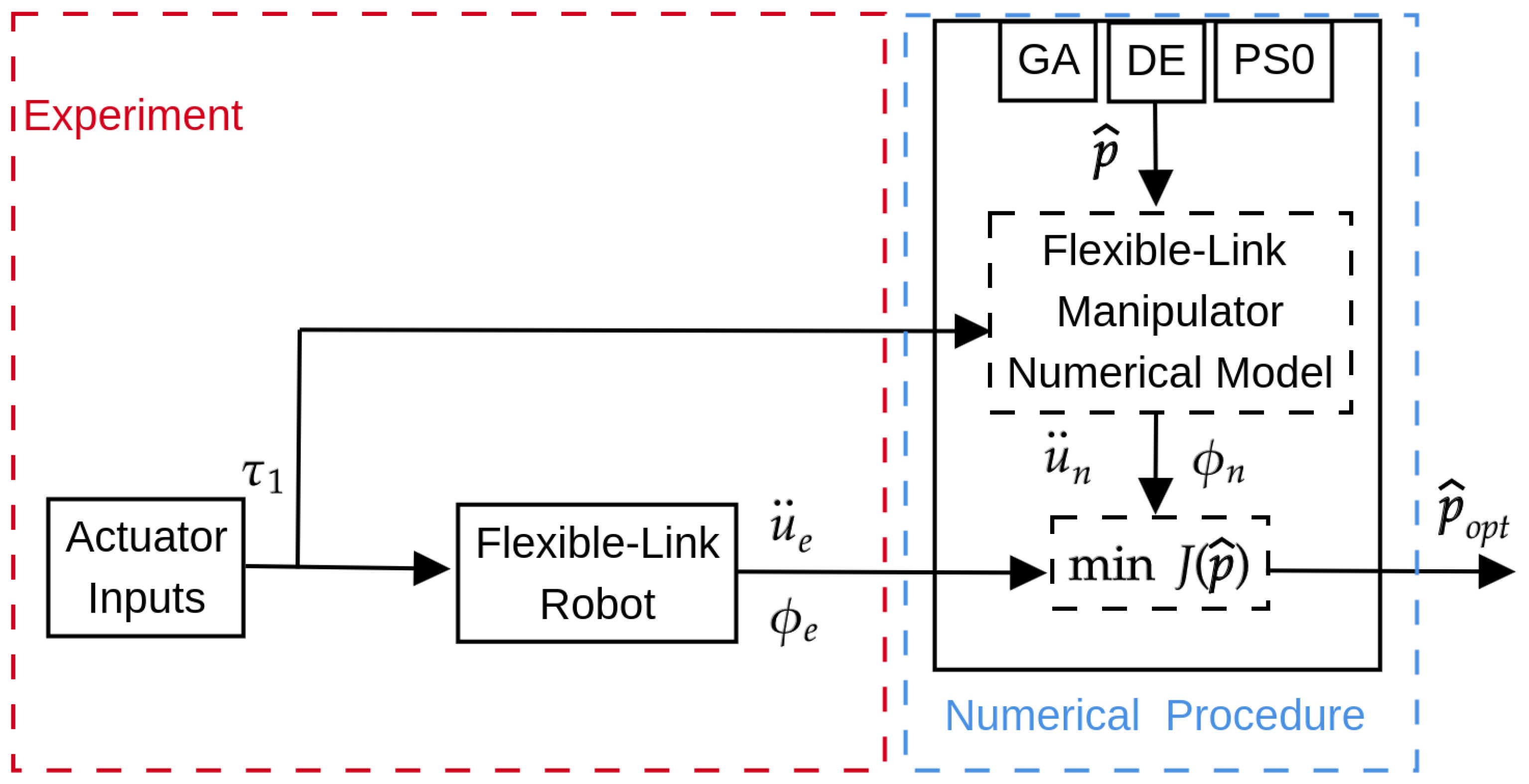
Figure 1. Parameter identification approach.
Machines 12 00409 g001
Figure 2. One-link flexible manipulator.
Machines 12 00409 g002
Figure 3. Finite element method: one-link flexible manipulator.
Machines 12 00409 g003
Figure 4. Inputs and outputs from experimental measurements used for J ( p ^ ) of Equation (6).
Machines 12 00409 g004
Figure 5. Objective function: convergence along generations and dispersion range. DE (); GA (); and PSO ().
Machines 12 00409 g005
Figure 6. Dynamic response of the numerical model obtained with the best parameters: Experimental (- -); DE (); GA (); PSO ().
Machines 12 00409 g006
Figure 7. Model validation approach.
Machines 12 00409 g007
Figure 8. Dynamic response with triangular torque input τ 1 : Experimental (); Numerical ().
Machines 12 00409 g008
Figure 9. Dynamic response with pulse torque input τ 1 : Experimental (); Numerical ().
Machines 12 00409 g009
Figure 10. Dynamic response width sinusoidal torque input τ 1 : Experimental (); DE ().
Machines 12 00409 g010
Table 1. Design space used in the model parameter identification.
ParameterUnitsLower Limit ( p ^ l )Upper Limit ( p ^ r )
EPa20 × 109100 × 109
I m kg m21 × 10−30.2
vNm/(rad/s)1 × 10−50.3
τ c N m1 × 10−30.2
α -1 × 10⁻³⁴
β -1 × 10−72 × 10−4
Table 2. Best optimal solution obtained from GA, DE, and PSO.
ParameterDEGAPSO
E [Pa] 5.7002 × 10 10 6.0665 × 10 10 5.6597 × 10 10
I m [kg m2]0.00530.00730.0048
v [Nm/(rad/s)] 6.3016 × 10 4 1.0000 × 10 5 1.0802 × 10 5
τ c [N m]0.10710.05890.0902
α 1.82400.20200.8055
β 7.6275 × 10 5 1.1754 × 10 4 3.7784 × 10 5
Table 3. Mean ( μ ) and standard deviation ( σ ) of p ^ using DE.
Parameter μ σ
E [Pa] 5.1580 × 10 10 6.3153 × 10 9
I m [kg m2]0.0045 7.6139 × 10 4
v [Nm/(rad/s)]0.00690.0036
τ c [N m]0.08040.0194
α 0.98600.5927
β 8.1550 × 10 5 5.7293 × 10 5
Table 4. Joint and F R F error evaluation.
Torque Input ( τ 1 ) NRMSE ϕ NRMSE FRF
Triangular2.85561.7092
Rectangular5.02351.5390
Sinusoidal6.08961.5093
Disclaimer/Publisher’s Note: The statements, opinions and data contained in all publications are solely those of the individual author(s) and contributor(s) and not of MDPI and/or the editor(s). MDPI and/or the editor(s) disclaim responsibility for any injury to people or property resulting from any ideas, methods, instructions or products referred to in the content.