Article

Digital Simulation of Coupled Dynamic Characteristics of Open Rotor and Dynamic Balancing Test Research

by
Yixiang Guo
1,
Lifang Chen
2,*,
Yuda Long
1 and
Xu Zhang
2
1
Key Laboratory of Engine Health Monitoring-Control and Networking of Ministry of Education, Beijing University of Chemical Technology, Beijing 100029, China
2
State Key Laboratory of High-End Compressor and System Technology, Beijing University of Chemical Technology, Beijing 100029, China
*
Author to whom correspondence should be addressed.
Machines 2024, 12(6), 391; https://doi.org/10.3390/machines12060391
Submission received: 30 April 2024 / Revised: 29 May 2024 / Accepted: 4 June 2024 / Published: 5 June 2024
(This article belongs to the Section Electrical Machines and Drives)

Abstract

:
An aero engine, as the core power equipment of the aircraft, enables safe and stable operation with a very high reliability index, and is an important guarantee in flight. The open rotor turbine engines (contra-rotating propeller) have stood out as a research hotspot for aviation power equipment in recent years due to their outstanding advantages of low fuel consumption, high airspeed, and strong propulsion efficiency. Aiming at the problems of vibration exceeding the standard generated by imbalance during the operation of the dual-rotor system of aircraft development, the difficulty of identifying the coupled vibration under the micro-differential speed condition, and the complexity of the dynamic characteristic law, a kind of numerical simulation of the dynamics based on the finite element technology is proposed, together with an experimental research method for the fast and accurate identification of the coupled vibration of the dual-rotor system. Based on the existing open rotor engine structure design to build a simulation test bed, establish a double rotor finite element simulation digital twin model, and analyze and calculate the typical working conditions of the dynamic characteristics of parameters. The advanced algorithm of double rotor coupling vibration signal identification is utilized to carry out decoupling and dynamic balancing experimental tests, comparing the simulation results with the measured data to verify the accuracy of the technical means. The results of the study show that the vibration suppression rate of the finite element calculation simulation test carried out for the simulated double rotor is 98%, and the average vibration reduction ratio of the actual field test at 850 rpm, 1000 rpm, and 3000 rpm is over 50%, which achieves a good dynamic balancing effect, and has the merit of practical engineering application.

1. Introduction

The open rotor engine (no culvert fan engine) is a gas turbine engine in which high-temperature and high-pressure gas impinges on the turbine, driving the output shaft to generate power to drive the propeller fan. It is a new concept of aviation power equipment between the turboprop engine with an advanced propeller and the turbofan engine, with a multiple wide chord, thin-blade type swept back propeller, as well as a double-row rotor counter-rotating structure, and with no culvert on the periphery of the rotor in the higher air-speed operating conditions to ensure a certain degree of propulsive efficiency, the effective culvert ratio is as high as 25–60%, indicating that the double-row counter-rotating open-rotor engine, compared to the structure of a single row of propellers, has a better fuel economy value. Combining the low fuel consumption of the turboprop engine and the high flight speed of the turbofan engine, it has become a high-quality alternative power source for the new generation of civil aircraft and military transport aircraft to achieve the goal of energy saving and emission reduction [1].
Many scholars at home and abroad have carried out a series of research works on the analysis of dynamic characteristics and the identification of coupled vibration signals based on the coaxial twin rotor structure (coaxial co-rotation/coaxial counter-rotation) in the context of the double-row open rotor engine. Zhang Zhixin [2,3] and others seized the key point of the machine balancing of a micro-velocity difference dual-rotor system, successfully separated the respective unbalance components of the inner and outer rotors from the complex coupled beat vibration signals, and developed and researched a portable intelligent machine balancing instrument for the micro-velocity difference dual-rotor system. In order to evaluate the vibration coupling effect of the intermediate bearing on the double rotor system, Wang Jie [4] and others explained the manifestation of the double rotor coupling vibration and the internal relevance from the angles of the rotor’s critical rotational speed and positional vibration changes, modal vibration and intermediate shaft bearing force changes, etc. [5,6,7], and put forward the corresponding evaluation indexes and evaluation methods, which were analyzed and evaluated for the typical gas turbine engine with double rotor system as a research object. The method provides a reference for the design and troubleshooting of double rotor-mediated bearing systems. Song Ziyu et al. [8] used the mechanical impedance theory to quantitatively characterize the structural mass/stiffness distribution of a dual rotor system with a shared load-bearing frame between turbine stages, established a vibration coupling mechanism model for a complex rotor system, and proposed a method for determining the vibration coupling point for a shared support-dual rotor system. The simulation results show that the mechanical nature of the vibrational coupling of the two-rotor system is the coupling of the dynamic response under the vibrational interaction between the rotor and the supporting structure [9,10,11,12]. It includes both the vibration coupling mechanical behavior brought about by the vibration foundation excitation of the shared support structure, and also the vibration response coupling mechanical behavior of multi-frequency combinations under the interactive excitation of multiple rotors.
Zhang Dayi et al. [13] addressed the whole-engine dynamics of an aero-engine rotor and used a whole-engine dynamics model to solve the vibration characteristics of the engine. The simulation results show that there exists only a first-order high-pressure rotor advection vibration pattern in the interval between the slow and maximum rotational speeds, and the overall total strain energy of the rotor system is not more than 20%, with a resonance margin of more than 20%, which meets the kinetic design requirements of the rotor of the aircraft engine. Ouyang Yunfang et al. [14] took the twin-rotor aero-engine system without intermediary bearings as the research object, used the method of centralized mass to establish the dynamics model of the twin-rotor–bearing–cabinet coupling, and simulated and studied the touching failure of the inner and outer rotors, respectively [15], and at the same time extracted the characteristics of the touching failure of the inner and outer rotors, but there is a lack of comparative work in experimental validation. In the dual-rotor system of an aircraft engine, considering the extruded oil film damper as well as the nonlinear force of the intermediate bearing, Wang Fei et al. [16] modeled the coupled dynamics of the dual-rotor system with the help of finite element technical means [17,18,19,20]. The simulation calculates the effect of speed ratio on the nonlinear response characteristics of the rotor system, and it is found that the cross-excitation phenomenon can be clearly observed in the response, and the coupling frequency is different for different speed ratios, and the speed ratio has a large effect on the axial trajectory and motion period of the rotor system.
In the course of the study of the dynamic behavior of unbalanced multi-frequency dynamics occurring simultaneously at different speeds of multiaxial rotating machinery, Mikhail Guskov et al. [21] proposed a generalized method of harmonic balancing [22,23] with arc-length extension, which corrects the nonlinear response of the Jeffcott rotor system under the action of multiple unbalances. For the research of the accurate identification and fault traceability diagnosis of aero-engine vibration signals, domestic scholars Pi Jun et al. [24] proposed a blind source separation algorithm based on the cumulative amount of improved independent component analysis. The new method was applied to separate the rotor vibration signals [25] and identify the fault types, which showed a significant improvement in terms of performance indices and signal similarity coefficients. Feng Guoquan et al. [26] investigated the vibration characteristics and unbalance response of a rotor system with initial bending, established a multi-degree-of-freedom analytical model suitable for engineering applications from the theory of rotor dynamics, and illustrated the dynamics characteristics through the computational analysis of an actual rotor system. Jasmine Chen et al. [27,28,29] carried out simulation analysis and experiments by using the multidimensional graphical method for the small frequency difference problem of beat vibration. The traditional two-beat vibration theory was extended to multi-source beat vibration [30,31], and the upper and lower limit amplitudes and fundamental frequencies of beat vibration were obtained. Experimental studies have shown the correctness of the upper and lower limits of amplitude, and the fundamental frequency of beat vibration obtained by multi-source beat vibration theory [32,33,34,35,36], which proves the effectiveness of the multidimensional graphical method in the real-time observation and analysis of small-frequency difference vibration phenomena.
Luciano Paiva Ponci [37] and others proposed a new vibration analysis and dynamic balancing program for mechanical systems affected by beat frequency, which uses traditional hardware and software to adjust data acquisition parameters, and has significant advantages in terms of maintenance costs and response speed. Aleksandar Vencl et al. [38] used rolling bearings in rotor systems as a starting point for their study and constructed a rolling bearing fault tree (FTA) based on the main types of bearing wear (abrasive wear, surface fatigue wear, and corrosive wear, etc.) to determine the root causes of bearing failures. Limited by the inapplicability of frequency–domain techniques for the steady-state cyclic vibration of rotor unbalance systems with nonlinear bearings to real structures such as aero-engine assemblies, Philip Bonello [39] et al. proposed an RHBM methodology that enables the frequency–domain analysis of such structures. The results of this study have shown that the RHBM is a very powerful tool that can greatly facilitate the analysis of nonlinear dynamics of real engine structures [40]. A Sembiring [41] et al., in their analysis of a coaxial twin rotor multi-degree of freedom system, solved the equations of motion of the system numerically using the MATLAB r2017b programming language, and the results of the simulated modal method [42] and the direct method were also compared, and the most effective method of predicting the critical rotational speed was obtained through the plotting of Campbell’s diagrams. A. Nandi [43] proposed a simplified method for the finite element modeling of non-axisymmetric rotors based on non-isotropic spring supports. The stiffness matrix, mass matrix, and Coriolis matrix of a non-axisymmetric rotor are independent of time, but the support force is a periodic function of time, which results in the need to deal with a large number of linear ordinary differential equations with periodic coefficients in the position of the support degrees of freedom, and therefore requires a large amount of computation quantities. The proposed method can handle this large system efficiently and simplify the computation while being able to keep the main information of the system intact.
In summary, scholars at home and abroad have conducted relevant research work on the dynamic modeling, numerical simulation analysis and coupled vibration characteristic mechanism of the typical structure of double rotors of aircraft engines. However, most of the research results focus on the simulation and numerical study of the separation algorithm of the coupled vibration signal, or the simulation and analysis of the dynamics of the typical working conditions of the dual-rotor structure, without comprehensively evaluating the agreement between the theoretical modeling simulation and the experimental test, and the lack of guided support in the process of practical engineering applications. In addition, there is not much representation of the measures and technical means to solve the problem after the unbalanced fault characteristics of the double rotor structure. To address the above problems, the main contribution of this paper is to design and build a physical platform of a double-row open rotor simulation tester, and establish a finite element simulation model to carry out the calculation and analysis of dynamic characteristics. Further, the vibration coupling mechanism of a typical dual-rotor structure is studied, and the independent vibration responses of the inner and outer dual rotors are more accurately and actively identified, and the dynamic response law and vibration characteristics of a typical dual-rotor structure are more comprehensively characterized through the comparison of onsite experimental test data and simulation results. Combining the simulation test bench and finite element simulation model, we comprehensively study the rotor dynamics based on the double-row open rotor structure, and lay the research foundation for guiding the structural design of the double rotor, the dynamic evaluation of the working conditions, and the fault diagnosis and active regulation of the vibration highlighting problems.

2. Simulation of Double-Row Open Rotor Structure

The double-row contra-rotating propeller structure shares a concentric shaft with two intermediate bearings acting as stiffness supports. The two rows of propellers rotate in the opposite direction, and the rear blade grille changes the flow direction of the vortex generated by the front row of propellers, so that it is twisted to flow in the axial direction, increasing the total thrust and propulsive efficiency of the engine. Taking the existing propulsive direct-drive double-row open-rotor engine as the technical background, the specific structural principle is shown in Figure 1 to design and build the counter-rotating double rotor simulation tester used in this study.
The design idea is benchmarked against the existing double-row open rotor engine double rotor structure, with two intermediary bearing positions as well as double-row propeller positions as axial positioning, and a concentric embedded design of inner and outer rotors.
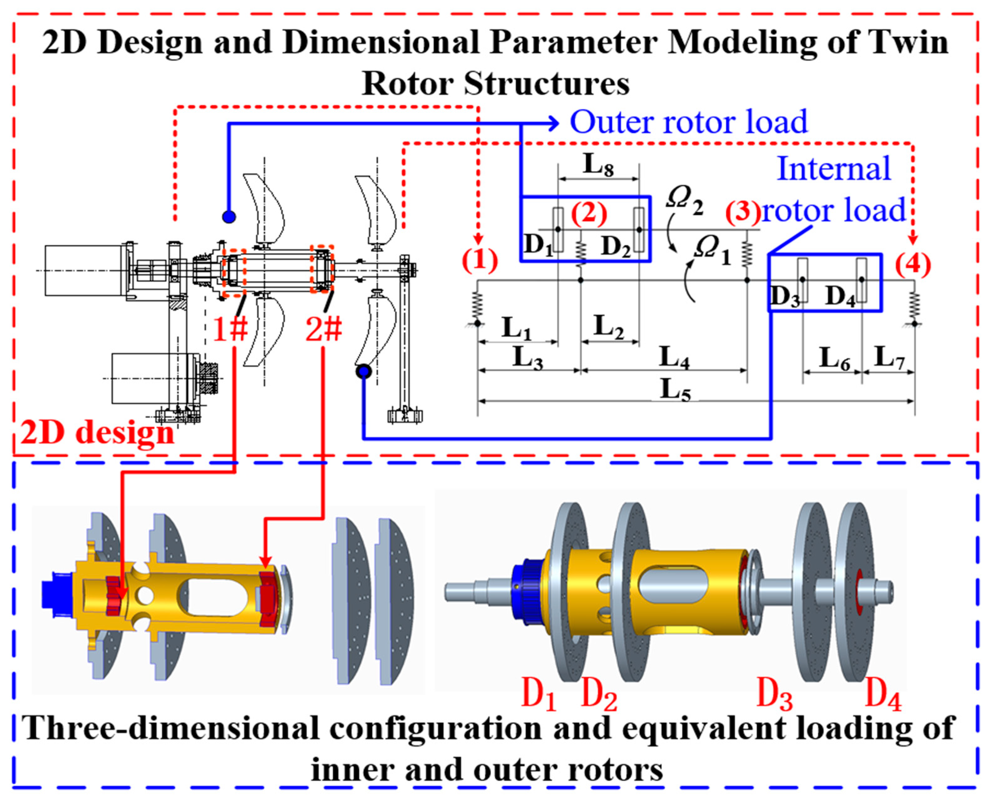
The inner rotor is directly connected to the inner rotor drive motor through a coupling, and the outer rotor is belt driven by the outer rotor drive motor through a synchronous pulley at the end of the shaft. The inner rotor can be fitted with a front analog propeller and counterweight disk, and the outer rotor can be fitted with a rear analog propeller and counterweight disk. Only the lateral vibration of the dual-rotor system is considered in the 3D coordinate system O-xyz, and the inner and outer axes of the rotor are symmetrical in structure and homogeneous in material. The kinetic simulation model of this dual-rotor system can be established by using finite element technology, and the structural design and mechanical model of the dual rotor is shown in Figure 2.
The typical structure of a double rotor is simplified to a two-axis and four-disk configuration based on the support at both ends, the support at the intermediate bearing position, the front and rear propeller rotor positions, and the positions of the inner and outer rotor counterweight disks. The specific simulated double rotor structural parameters are shown in Table 1, and the empirical parameters of the four support bearings are shown in Table 2.
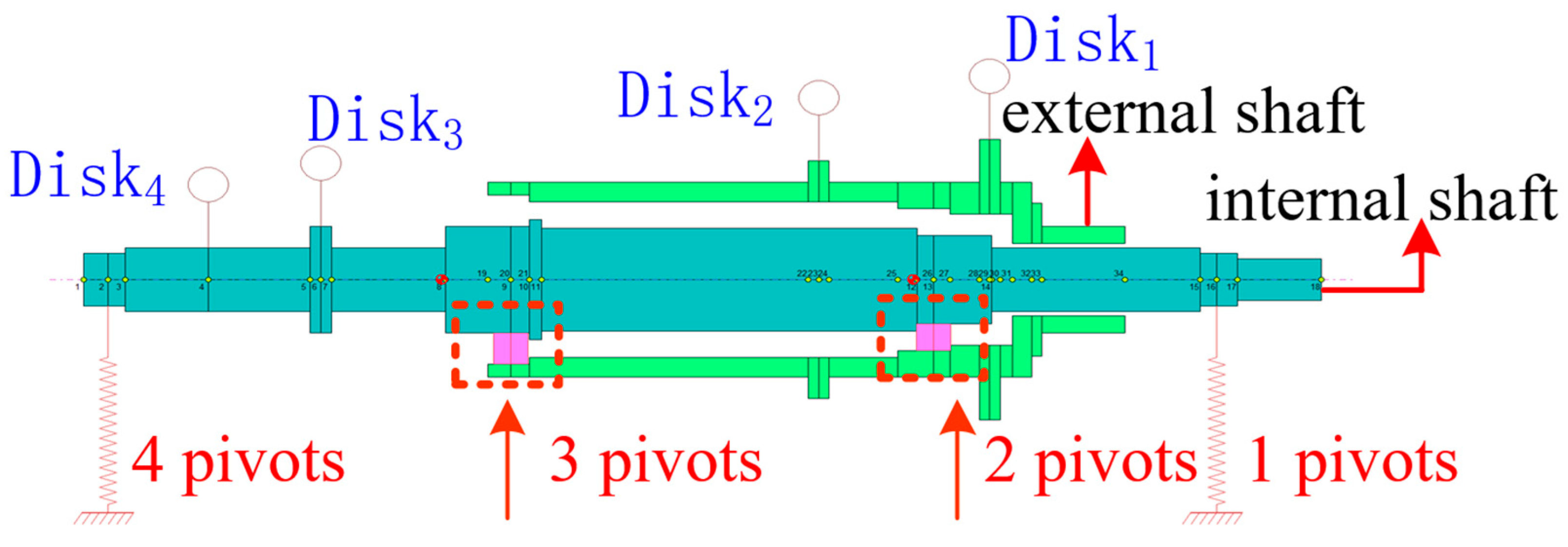
The kinetic similarity criterion is satisfied to establish a finite element model of a typical double rotor analog structure. The simulated propeller, as well as the counterweight disk, are represented by Disk cells with equal mass and moment of inertia, the support bearing is given isotropic stiffness coefficients in both directions, and nodal cells are guaranteed at the centralized mass, the sudden change in the shaft diameter, and at the bearing support, and the simulated double rotor finite element discrete model is shown in Figure 3.
The model contains 18 nodes for the inner shaft and 16 nodes for the outer shaft, with 1–4 pivot points grounded at each end of the inner shaft and 2–3 pivot points in the center for the double rotor intermediate bearings. The internal and external simulated propeller rotors are equivalently divided into two disk units with specific parameters, shown in Table 3.
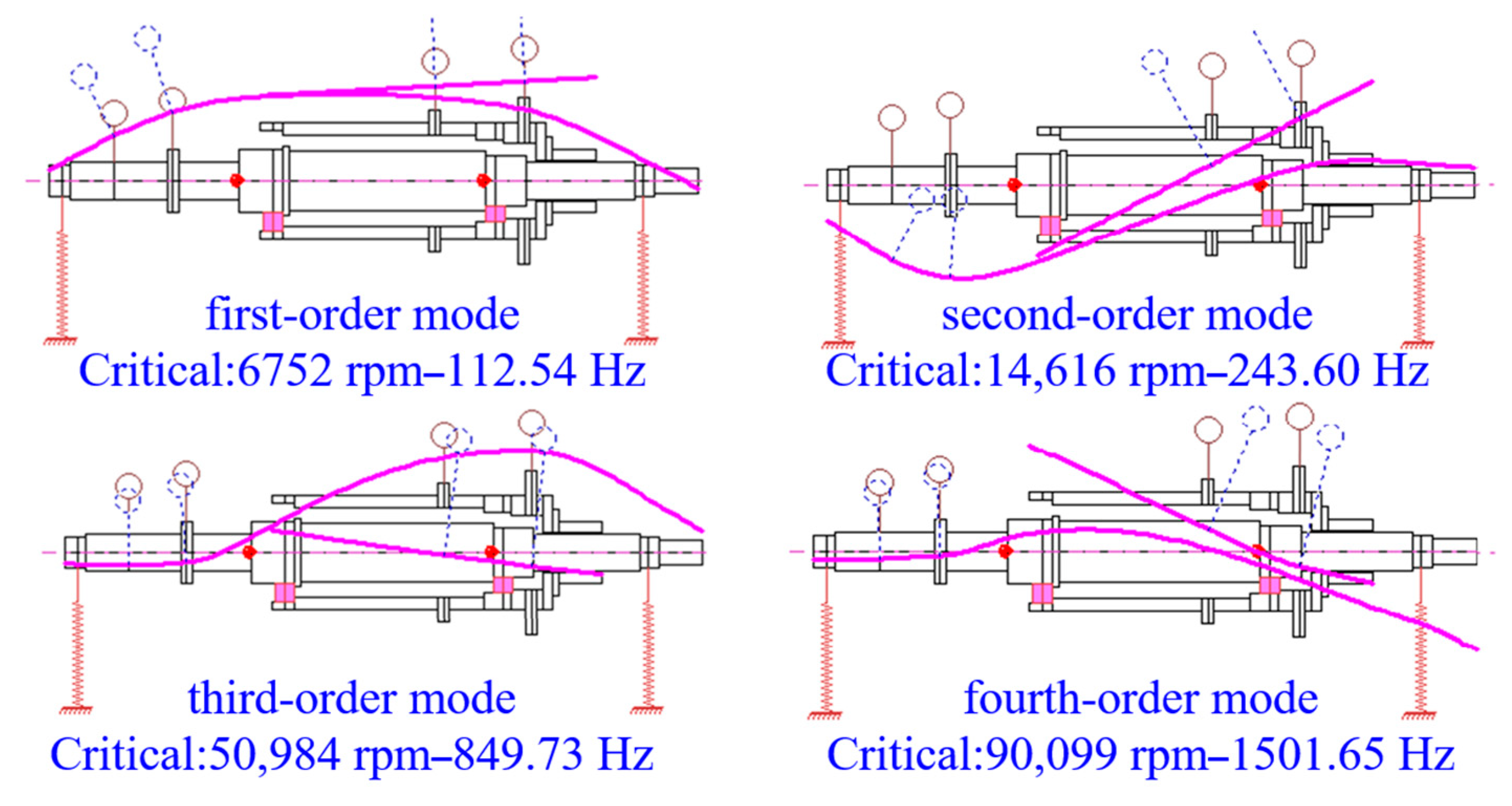
The critical speed analysis is carried out for the double rotor finite element model, and the first four orders of modal vibration patterns are obtained as shown in Figure 4. From the analysis and calculation, it can be seen that the first-order critical speed of the dual-rotor test bench is 6752 rpm, while the actual dual-rotor working speed is 1000 rpm, with a safety margin of 85.2%, which is a typical rigid rotor, and can be carried out for subsequent experimental research.

3. Simulation of Open Rotor Coupling Dynamics

A double-row open rotor simulation dual-rotor model is established, and the dual-rotor dynamic balance simulation test is carried out through the modal simulation of the rotating dual rotor and the frequency sweep analysis of the steady-state response.
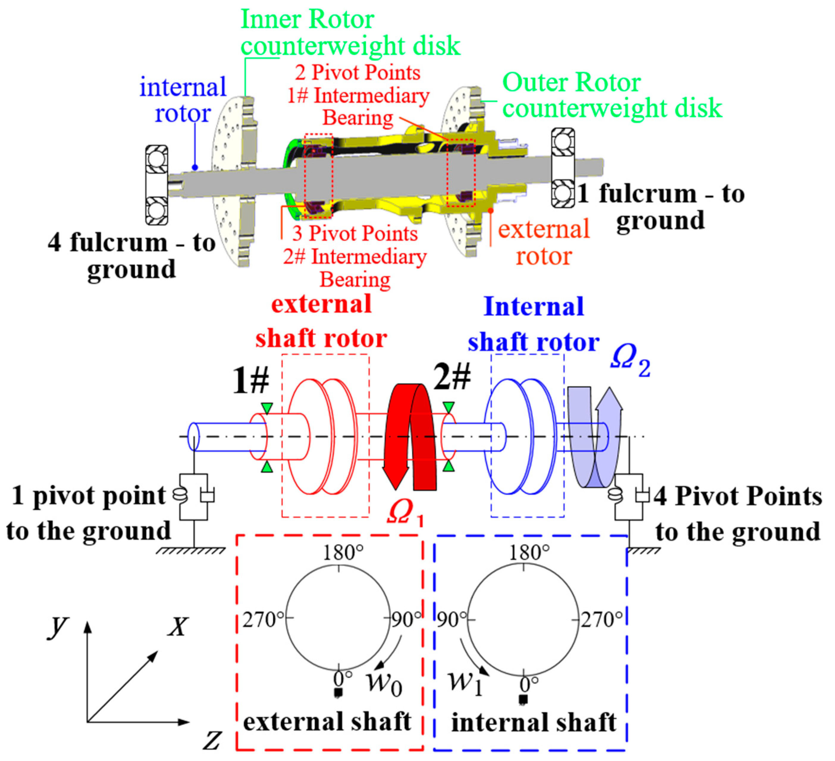
The modeled structure consists of an inner rotor shaft, an outer rotor shaft, inner and outer rotor counterweight disks, two ground support bearings, and two intermediary bearings, as shown in Figure 5. By studying the effects of the multiple couplings of internal and external rotor inertia, damping, and stiffness on the dynamic characteristics and performance of the dual-rotor structure, we also observe the coupled dynamics behavior of the dual-rotor system and analyze the results of the simulation calculations.

3.1. Twin Rotor Modal Simulation

First, the geometric model of the double rotor structure was imported into the FEA software (ANSYS 17.0). Next, finite element meshing is performed on the model to select the appropriate grid cell type. Thirdly, to define the material properties, the material of the twin-rotor structure is all structural steel, which has a density of 7850 kg/m3, a modulus of elasticity of 206,000 N/mm2, and a shear modulus of 79,230 N/mm2. Fourth, the boundary conditions and loading are applied. The double rotor structure is a simply supported beam and contains two ground support bearings and two intermediate bearings. Finally, the modal analysis calculation parameters are set to define the number of modal orders for the solution. After the calculation is completed, the results of the modal simulation of the double rotor are analyzed, specifically including its intrinsic frequency, mode shapes and critical speed values.
In order to improve the accuracy of the simulation calculation, the simulation of the double rotor structure finite element model uses a meshing selection of regular hexahedral and tetrahedral mesh, with a mesh body size of 2 mm, a mesh total number of cells of 3,259,414, the number of nodes is 4,720,860, and it has an average mesh quality of 0.84 > 0.7 to meet the requirements of the computational accuracy, and with this the theoretical convergence of the node force convergence and displacement convergence can be achieved. After mesh-independence verification, the meshing results for this model are proved to be reliable. The key to mesh-independence validation is the determination of an appropriate mesh density, such that further refinement of the mesh does not significantly affect the computational analysis results, improving the confidence level of the analysis results.
The boundary conditions (loads and constraints) of this model are set as bearing-to-ground contact at both ends of the inner rotor, and the inner and outer rotor intermediary bearing as body-to-body contact to provide support stiffness, which is used to transmit the coupled vibration response between the twin rotors, absorbing vibration signals from one node and transmitting them to the other node through the vibration response of the bearings themselves. In addition, the overall structure is subjected to standard gravity, and binding connections are set up at other contact locations.
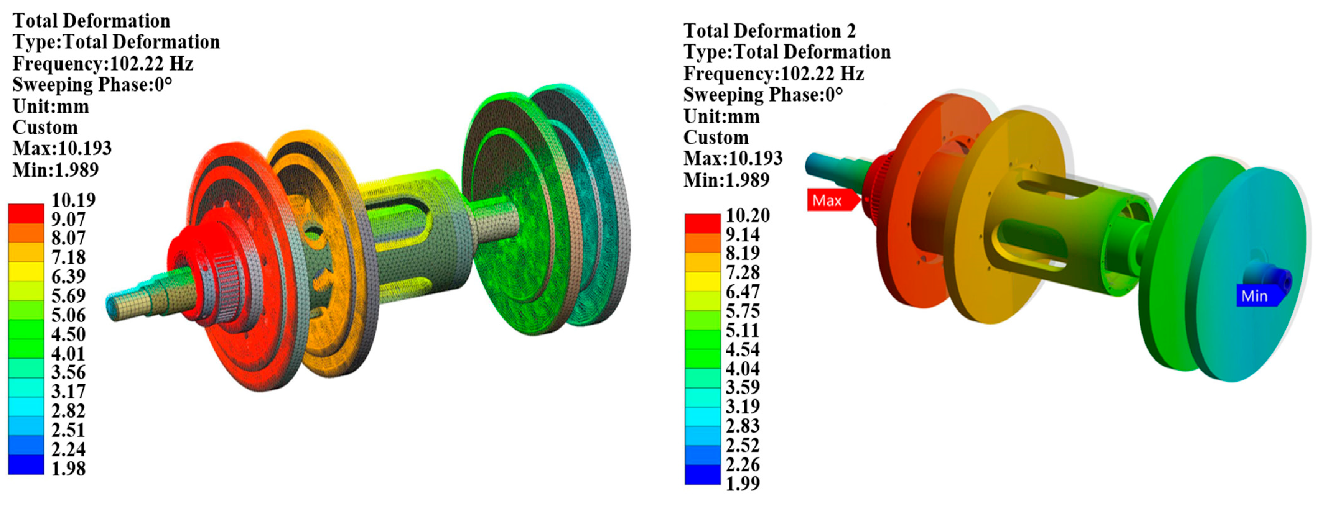
The specific calculation process is to extract the first 12 orders of modal vibration patterns of the simulated double rotor structure, using the MAPDL solver to solve the problem, and then the program control method is carried out, and the specific calculation results and the cloud diagram are shown in Figure 6.
From the calculation results in the above figure, it can be seen that the simulated first-order modal vibration natural frequency of the two-rotor structure (solid unit) is 107 Hz, and this value is 112 Hz from the two-dimensional beam unit modeling, and the deviation of the two calculations is ±5 Hz. Since this value is much larger than the maximum test frequency of the actual dual-rotor structure, the simulated coaxial dual-rotor structure will not generate system resonance during the speed test interval in the subsequent test phase, effectively avoiding the dangerous situation of rotor overcriticality, and the calculation results in this section can provide technical guidance for the verification of the test later.

3.2. Twin Rotor Steady-State Response Sweep

It is assumed that the overall stiffness, mass and damping matrices of the two-rotor structure are constant matrices versus frequency, and that there are no nonlinear problems as well as transient responses in the structure. In addition, the double rotor body loads (inertial loads) are not considered in phase, and the steady-state response is calculated as the control equation [45]:
[ M ] { U ¨ } + [ C ] { U ˙ } + [ K ] { U } = { F max e i ψ } e i Ω t
where Ω is the excitation frequency and t is the time variable.
During the harmonic response analysis of a two-rotor system, all the nodes in the structure move according to a certain frequency as well as different phases. Because of the different damping of the nodes in the structure, which produces different phases, the displacement of the twin rotor structure has an approximate expression for the external load:
{ u 1 } = { u 1 max e i ϕ 1 } e i Ω 1 t   = { u 1 max ( cos Φ 1 + i sin Φ 1 ) } e i Ω 1 t { u 2 } = { u 2 max e i ϕ 2 } e i Ω 2 t   = { u 2 max ( cos Φ 2 + i sin Φ 2 ) } e i Ω 2 t
where { u 1 } , { u 2 } are the inner and outer rotor displacement vectors, Φ 1   , Φ 2 represent the inner and outer rotor phases, and Ω 1   , Ω 2 are the inner and outer rotor excitation frequencies.
{ F 1 } = { F 1 max e i Ψ 1 } e i Ω 1 t   = { F 1 max ( cos Ψ 1 + i sin Ψ 1 ) } e i Ω 1 t { F 2 } = { F 2 max e i Ψ 2 } e i Ω 2 t   = { F 2 max ( cos Ψ 2 + i sin Ψ 2 ) } e i Ω 2 t
where { F 1 } , { F 2 } are the external loads on the inner and outer rotors, Ψ 1   , Ψ 2 represent the inner and outer rotor phases, and Ω 1   , Ω 2 represent the inner and outer rotor excitation frequencies.
The derivation of the expression for the nodal displacements corresponds to obtaining the nodal velocities and accelerations as:
{ u } = ( { u x } + i { u y } ) e i Ω t { u ˙ } = i Ω ( { u x } + i { u y } ) e i Ω t { u ¨ } = Ω 2 ( { u x } + i { u y } ) e i Ω t
The external load F, displacement, velocity and acceleration expressions are obtained by substituting them into the control equations for steady-state response calculation as follows:
( Ω 2 [ M ] + i Ω [ C ] + [ K ] ) ( { u x } + i { u y } ) = ( { F x } + i { F y } )
During the finite element simulation calculations, the complete method (the program uses sparse matrices) direct solver is used to solve the system of algebraic equations containing complex numbers, while the variational technique is turned on to improve the sweeping speed and computational efficiency. The sweep interval is set to 0–60 Hz (0–3600 RPM), and the sweep interval is 120 data points, i.e., every 0.5 Hz the program iterates the results until the calculation is complete.
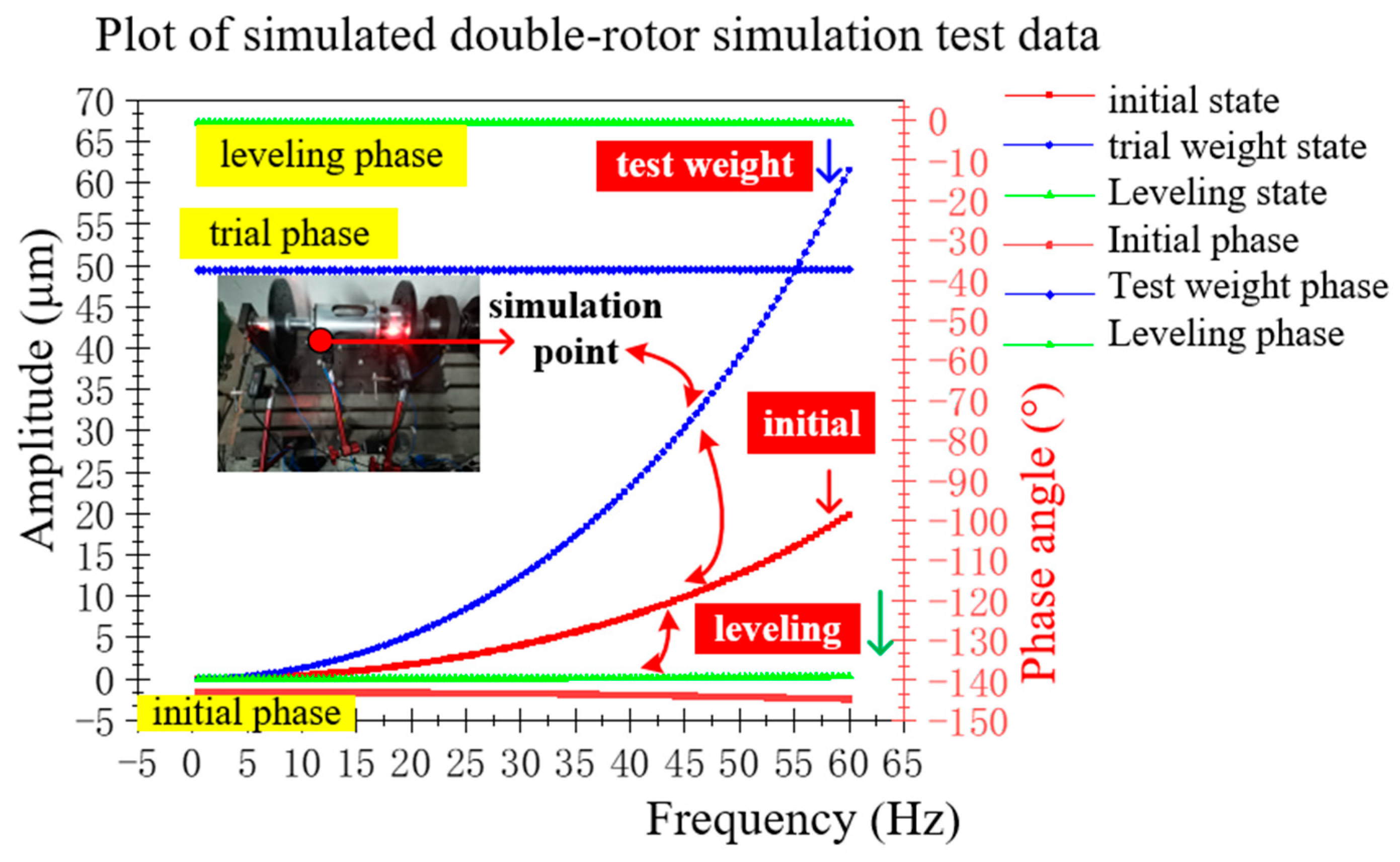
The simulation process simulates the original state of the coaxial double rotor structure, the test weight state, and the leveling state of the deformation response value of the measurement point position, calculates the frequency response curve at the measurement point, and draws the Bode diagram. The curves are plotted based on the vibration data calculated from the analog simulation tests, as shown in Figure 7.
From the figure, it can be clearly seen that after the leveling of the simulated dual-rotor structure at the location of the measurement point of the vibration response, the value decreased significantly (vibration suppression reduction ratio of 97.5%), achieving a good vibration suppression effect. The dynamic balancing simulation test in this part preliminarily verifies the validity of the independent dynamic balancing method based on the double correction plane of the double rotor structure, and lays a theoretical and technical foundation for the simulated onsite dynamic balancing test of the double rotor structure in Section 5.

4. Coupled Vibration Mechanism of Counter-Rotating Double Rotor

4.1. Theory and Properties of Pattern Oscillation

In the double-row open inner and outer rotor in the actual operation process, there is a certain speed difference, resulting in a micro-frequency difference of the two simple harmonic vibrations superimposed on each other and producing beat vibration. Assume that the vibration components of each of the inner and outer twin rotors are [35]:
X 1 = A 1 cos ( ω 1 + φ 1 )
X 2 = A 2 cos ( ω 2 + φ 2 )
where X1, X2 are the internal and external shaft vibration responses, A1, A2 represent the internal and external shaft vibration response amplitudes, ω 1 , ω 2 are the angular frequencies, and φ 1 , φ 2 are the initial phases.
Formed by superimposing two vibrational components:
X = X 1 + X 2 = A 1 cos ( ω 1 t + φ 1 ) + A 2 cos ( ω 2 t + φ 2 ) = A 1 2 + A 2 2 + A 1 A 2 cos [ ω 1     ω 2 2 t + φ 1     φ 2 2 ] × sin ( ω 1   +   ω 2 2 t + φ + φ 1   +   φ 2 2 )
From the above equation:
tan φ = A 1 A 2 A 1 + A 2 tan ( ω 1 ω 2 2 t + φ 1 φ 2 2 )
From the above formula, to draw the beat vibration waveform shown in the figure below, the original vibration signal frequency is ( ω 1 + ω 2 ) / 4 π . As can be clearly seen from the Figure 8, the beat vibration is constituted inside and outside the double rotor simple harmonic vibration component phase of the same peak (beat peak), corresponding to the specific amplitude of A max = A 1 + A 2 ; vibration component phase opposite to the occurrence of low values (beat valley), beat valley amplitude of A min = | A 1 A 2 | .

4.2. Coupled Vibration Identification and Decoupling

4.2.1. Coupling Mechanism and Identification of Double Rotor Vibration Signals

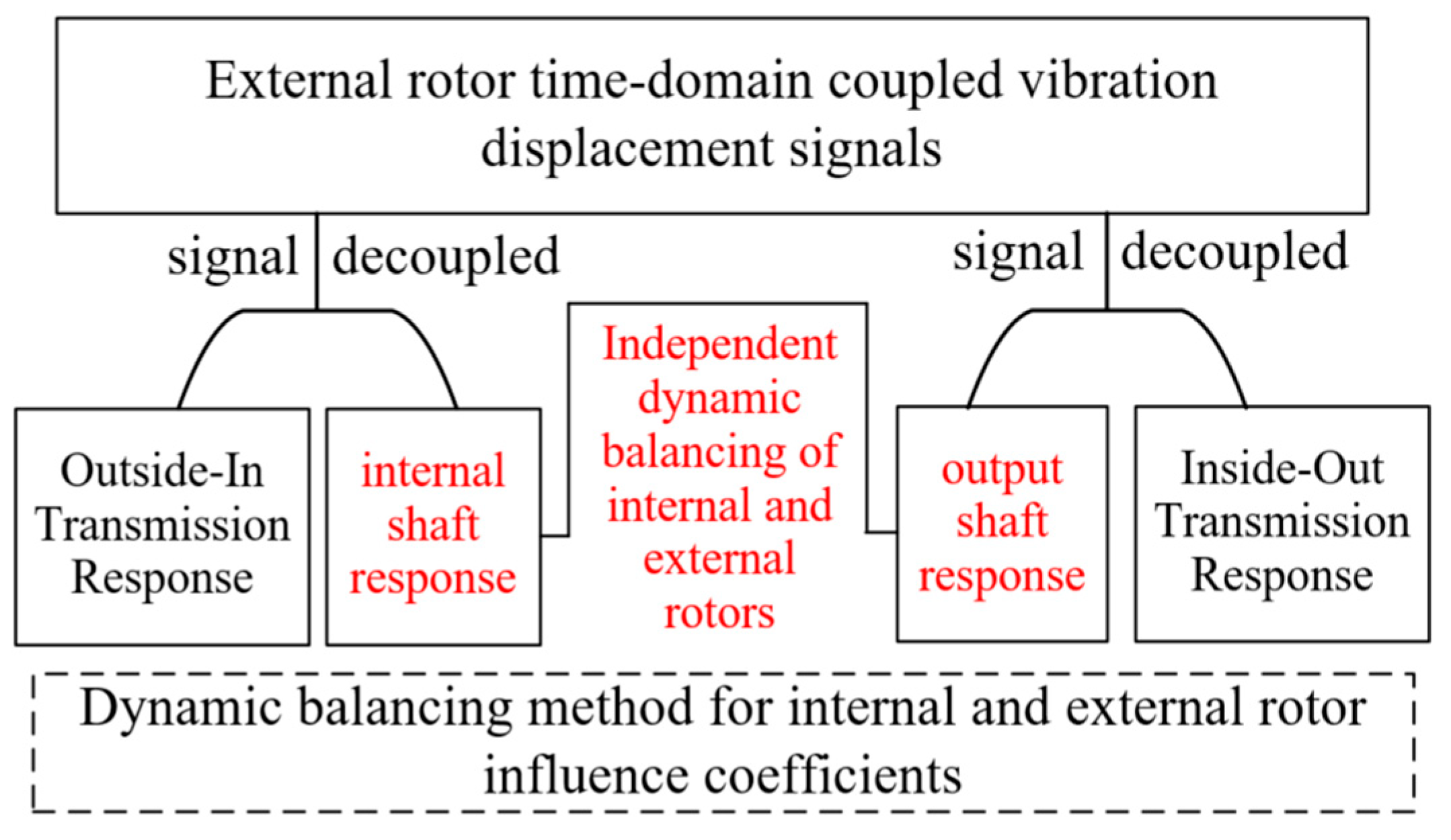
For the vibration signal test of the open double rotor, the decoupling of coupled signals can be realized by the method of micro-frequency difference. When the internal and external two rotor speed ratio is in the range of 1–1.5 Hz (60–90 rpm), it can be measured under the action of its mutual coupling vibration response, the waveform is mainly composed of two frequencies are very close to the sinusoidal signal composition, and this signal is the beat vibration signal. Digital signal processing is used to decouple the signals, thus extracting the respective unbalance responses of the inner and outer rotors, and obtaining the amplitude and phase information, so as to make technical preparations for the later simulation of dynamic balancing of the double rotor structure. The principle of coupled vibration signal identification and independent unbalance response extraction of inner and outer shafts is shown in Figure 9.
For the vibration transmission and coupling of the fundamental frequency signals of the twin rotor, the following method is used to carry out the study: assume that the natural vibration response of the inner shaft due to external excitation is x 1 ( t ) = A 1 sin ( ω 1 t + ϕ 1 ) , and similarly the vibration response of the outer shaft is set to x 2 ( t ) = A 2 sin ( ω 2 t + ϕ 2 ) .
In addition, taking into account the vibration transmission characteristics of the intermediary bearing between the inner and outer rotors in the dual-rotor structure, the vibration response of the inner shaft will stimulate the outer shaft to produce a new response x 1 ( t ) = A 1 sin ( ω 1 t + ϕ 1 ) , and the same reason can be obtained that the inner shaft, due to the stimulation of the outer shaft, produces a new response for the x 2 ( t ) = A 2 sin ( ω 2 t + ϕ 2 ) , and the coupling superimposed on each other, so the total vibration response of the inner shaft is:
y 1 ( t ) = x 1 ( t ) + x 2 ( t ) = A 1 sin ( ω 1 t + ϕ 1 ) + A 2 sin ( ω 2 t + ϕ 2 )
The total vibration response of the outer shaft is:
y 2 ( t ) = x 2 ( t ) + x 1 ( t ) = A 2 sin ( ω 2 t + ϕ 2 ) + A 1 sin ( ω 1 t + ϕ 1 )
Due to the similarity of the operating conditions of the inner and outer shafts of the double rotor and the portability of the vibration generation and transmission principle, only the unbalanced response of the inner shaft is specifically explained.
When the double rotor frequency is close and the difference is a constant value of ω , the vibration signal presents a beat vibration waveform, an amplitude with time periodic changes, and an amplitude contour that is for the envelope A ( t ) , specifically:
A ( t ) = A 1 2 + A 2 2 + 2 A 1 A 2 cos [ ( ω 1 ω 2 ) t + ( ϕ 1 ϕ 2 ) ]
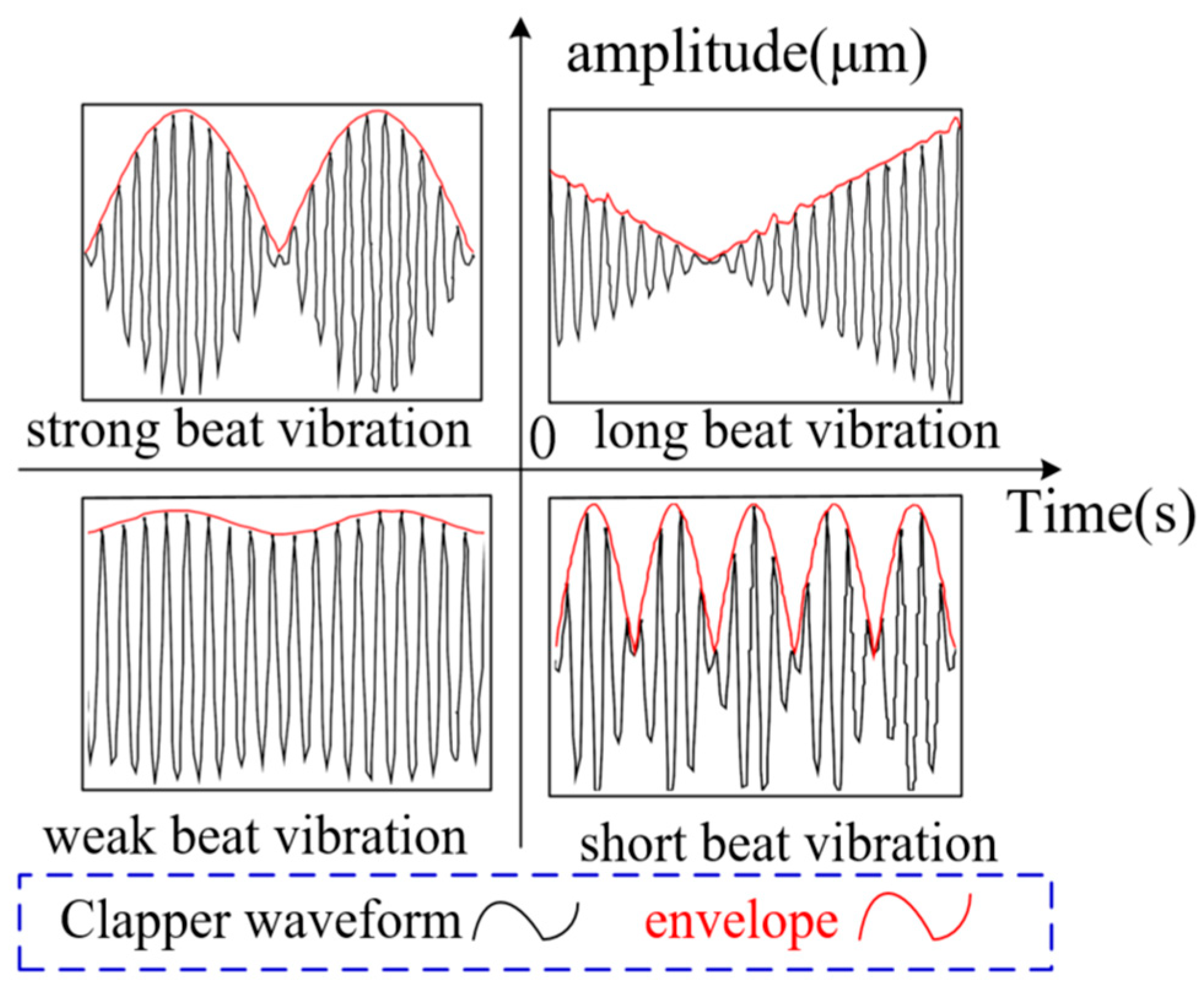
Based on the properties of the envelope, beat signals can be categorized into strong, weak, long, and short beats. When the coupled vibration signals are close to their respective amplitudes, there will be a strong beat; the amplitude gap is obvious when there will be a weak beat; when the difference between the internal and external rotor frequency is small, there will be a long beat; when the difference between the rotational speed is large, the beat vibration cycle is shortened to appear as short beat vibration. The measured results of the relevant beat vibration signals are shown in Figure 10.

4.2.2. Separation and Decoupling of Two-Rotor Coupled Vibration Signals

For the beat vibration phenomenon that occurs after the biaxial vibration coupling of an open rotor, analyzing the rotor amplitude and phase information by using the traditional fast Fourier transform will bring large inaccuracies [46]. Therefore, the least squares derivation algorithm is used to carry out the acquisition and identification of the unbalanced coupled vibration separation of the double rotor at working frequency. Considering that the open rotor vibration signal components are complex and diverse in operation, there are fundamental frequency signals and other white noise and harmonic components, simply relying on the least squares method to realize the decoupling of the double rotor vibration signal beat vibration, which will affect the computational speed and accuracy of the identification.
In this paper, using the least squares derivation algorithm, comprehensive considerations in the actual engineering applications may occur under the interference of unexpected factors of working conditions, so the application of the algorithm can still realize the fast and accurate analysis of the unbalanced coupled vibration of the double rotor, and improve the robustness of the signal identification and separation of the technical software test system.

5. Counter-Rotating Double Rotor Dynamic Balance Test

5.1. Open Rotor Simulation Test System

This test is based on the open rotor simulation test platform to carry out the relevant test validation work. The main components of the measurement and control platform of the simulation tester include software such as the Labview 2017 upper computer vibration analysis and monitoring system, which is equipped with a real-time rotational speed display of internal and external rotors, coupled vibration time–domain signals, FFT spectrograms, and internal and external rotor decoupled vibration amplitude and phase information; and influence coefficient calculation software based on the Labview platform, which can calculate the counterweight quality and position information according to the test weight situation, and provide technical support for the subsequent dynamic balancing of the double rotor; and the hardware mainly includes the internal and external rotor and drive motors, the counterweight disks, the servo motor driver, the NI vibration control box and vibration acquisition card, the eddy current displacement sensor, and the key-phase photoelectric sensor and supporting power module. The construction of the specific open rotor simulation test system is shown in Figure 11.
Among them: eddy current vibration sensor specific parameters are shown in Table 4.

5.2. Simulated Double Rotor Take-Off Speed Condition Dynamic Balancing Test

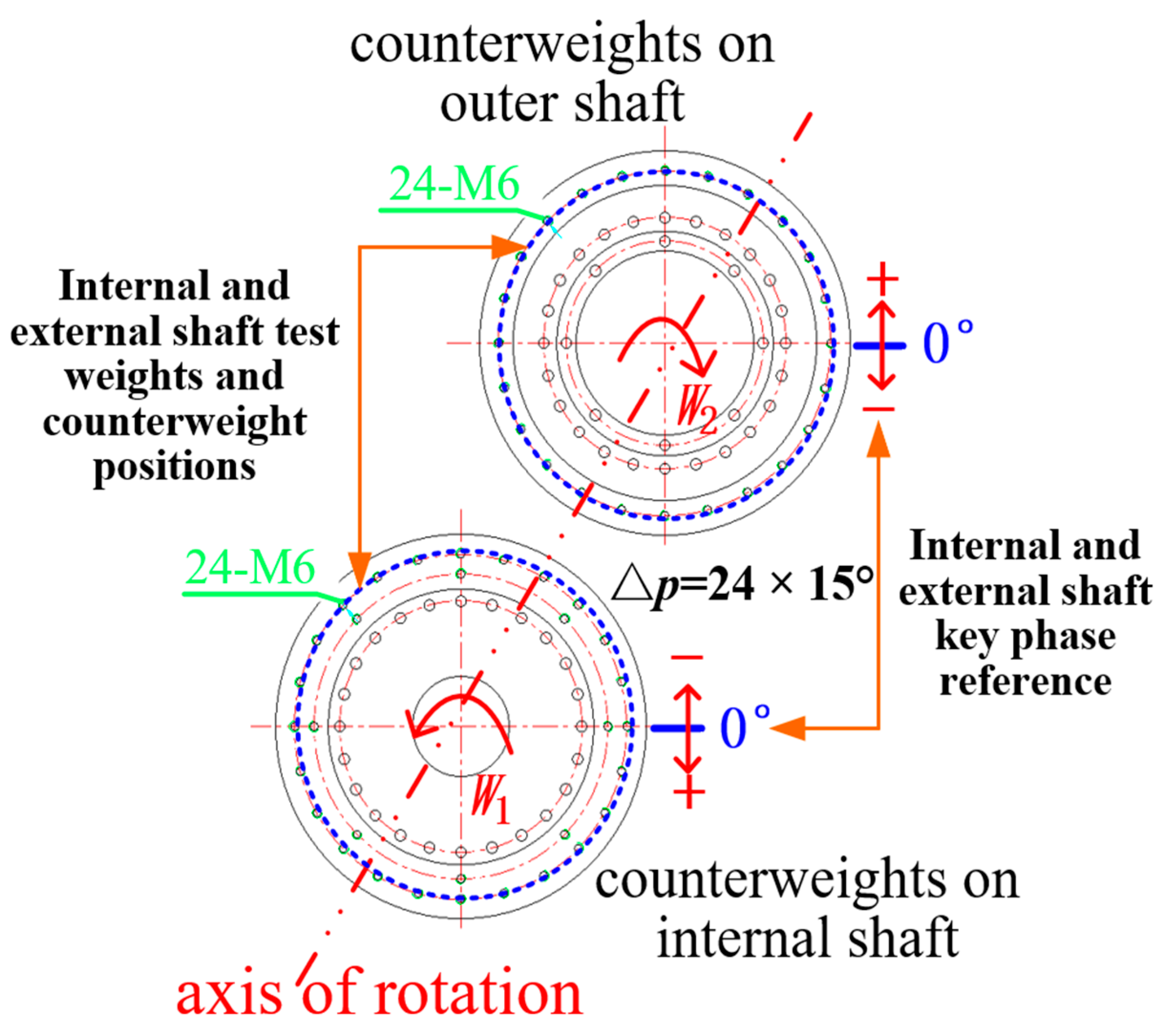
The propeller speed of the actual open rotor engine can reach 1000 RPM during taxiing for takeoff, so the simulation is used to test the dynamic balancing effect of the dual rotor structure at this speed. The test procedure uses 3–5 min of test time to simulate the full equivalent of an open rotor takeoff, which reduces a significant amount of ground simulation test time. Test speed: inner rotor 1000 RPM, outer rotor 1060 RPM, speed difference Δn = 1 Hz (60 RPM). Test process: first test the simulation dual-rotor system initial unbalance response, and then inside and outside the rotor, apply this to the test weight and record the test weight, and at this time start again at the target test speed to record the response information. According to the initial and post-test weight response information and the counterweight situation, the respective influence coefficients of the inner and outer rotors as well as the leveling parameters were calculated, and the specific test data are shown in Table 5.
Finally, the calibration mass is applied at the target leveling position of the inner and outer rotor counterweight disks, and the response of the double rotors is monitored at this time after starting the vehicle again, so as to test and observe whether the amplitude of the double rotors achieves a good suppression effect, and the above expression is a complete dynamic balancing operation process. Information on the direction of the rotation of the inner and outer rotors and the position of the counterweight disk is shown in Figure 12.
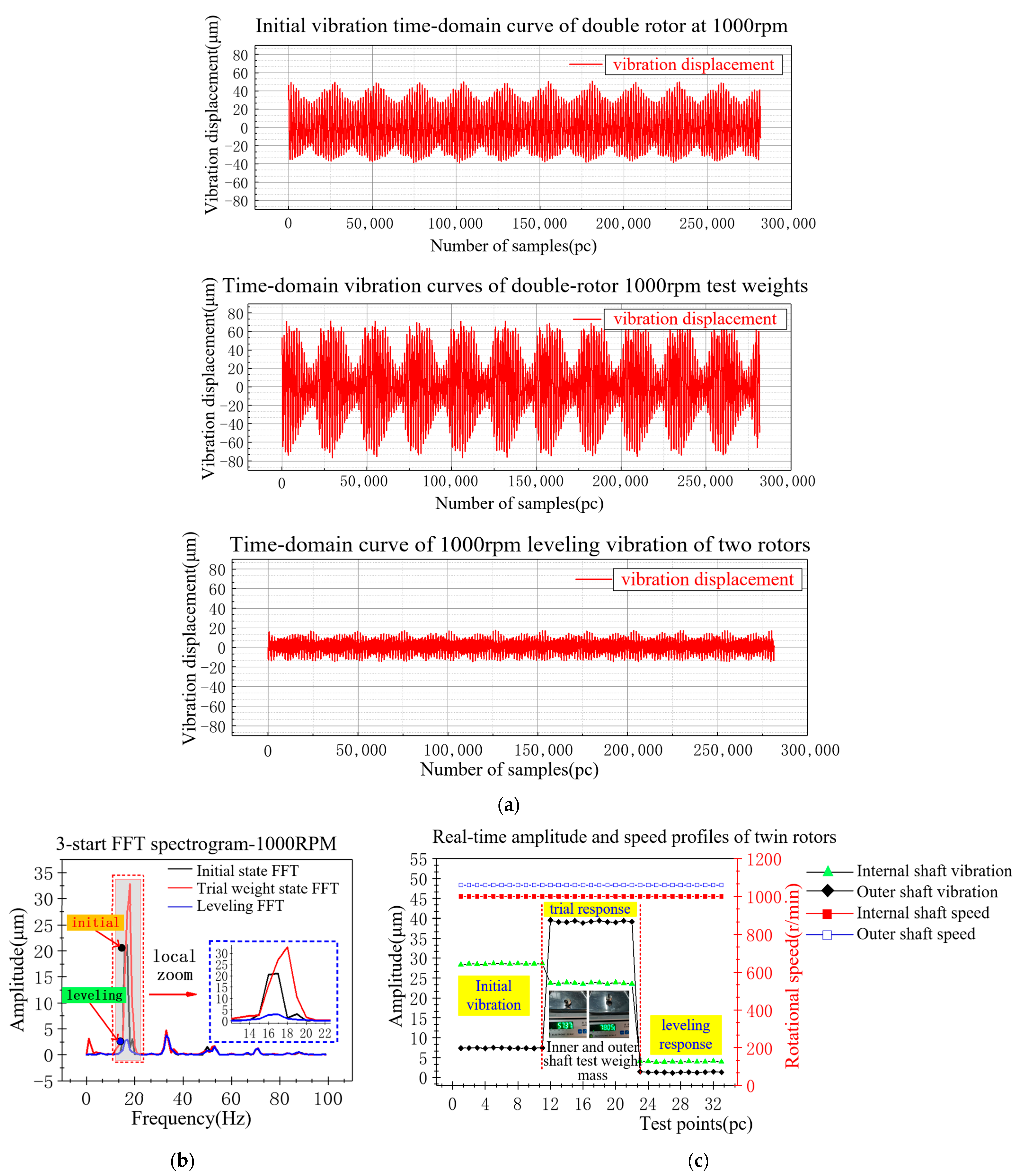
The test results of the simulated vibration response of the two-rotor structure after leveling are shown in Figure 13, where Figure 13a shows the original time–domain vibration displacement signals measured by the sensors at three starts (initial, test weight and leveling); Figure 13b shows the FFT spectrograms of the three starts; and Figure 13c shows the dynamic balancing vibration reduction curves of the inner and outer rotors and the real-time rotational speed graphs.
Analyzing the data in Table 6 reveals that, under the simulated working condition of the 1000 RPM take-off speed of the open rotor engine, the dual-rotor coupled vibration signal analysis algorithm based on dual-rotor coupling can accurately extract the respective unbalance response information of the inner and outer rotors, and then through the coaxial counter-rotation dual correction plane dual-channel influence coefficient, the dynamic balancing method can achieve the precise and stable target suppression of the vibration value of the simulated dual-rotor system under the rotational speed, and the effect of the dynamic balancing is obvious, which lays down a technological foundation for the application of the actual engineering.

5.3. Simulated Dual-Rotor Cruise Speed Condition Dynamic Balancing Test

According to the information, for a certain type of open rotor engine, after reaching the cruise state condition, the counter-rotating double rotor speed is reduced to 850 RPM because its flaps are capable of generating considerable lift. In order to realistically investigate the operating characteristics of the twin-rotor structure under actual cruising conditions, dynamic balance test experiments were conducted to simulate the twin-rotor structure at this speed. Test speed: inner rotor 800 RPM, outer rotor 860 RPM, speed difference Δn = 1 Hz (60 RPM), the specific test steps and test methods are consistent with those described in the previous section, and the actual test data are shown in Table 7.
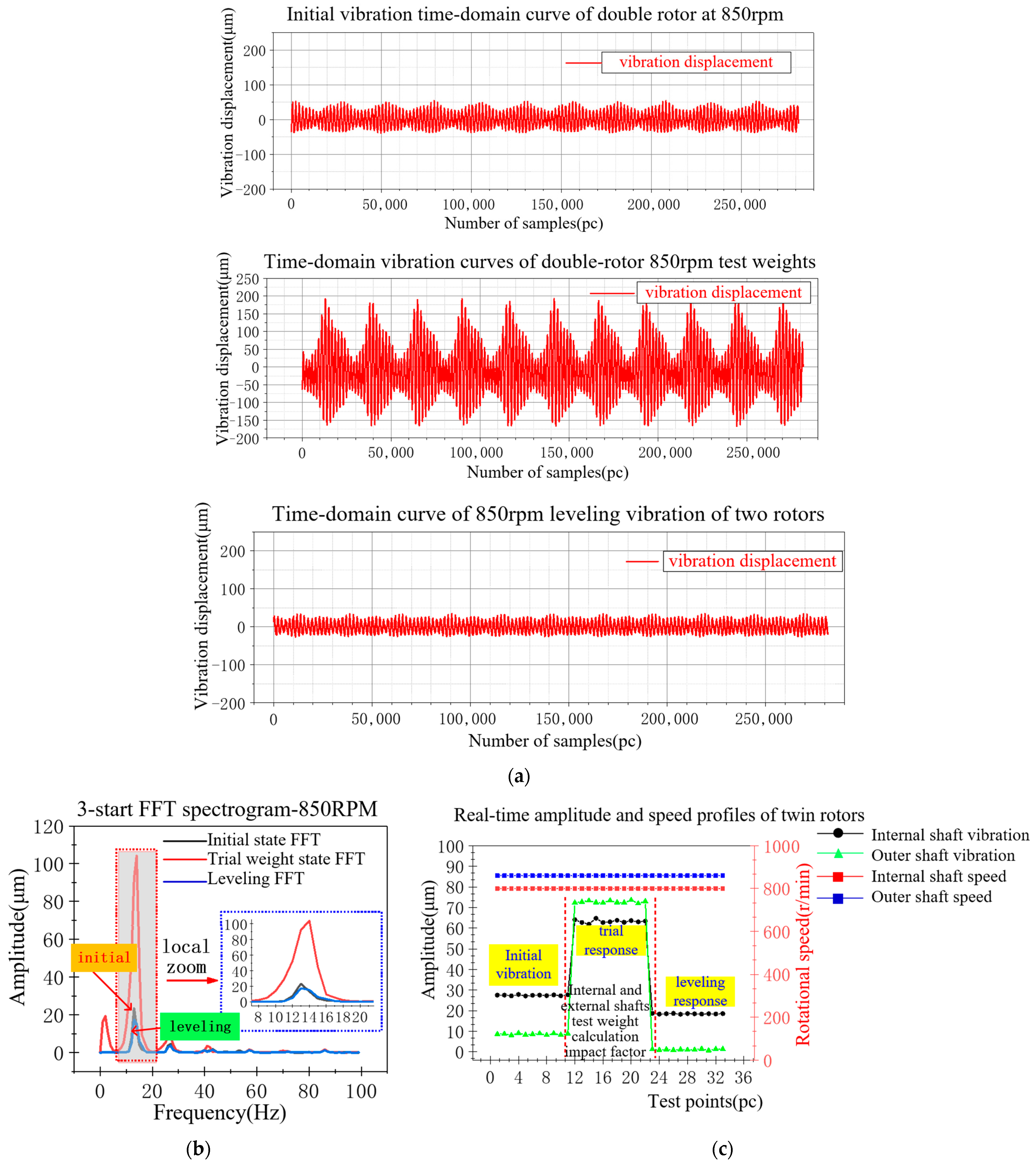
According to the data in the table, in the counterweight position, the inner and outer rotor counterweight disks were applied to the calibration mass. The stand test was started again to observe the changes in the vibration response of the inner and outer rotors, and the specific test process for the actual sensor monitoring of the vibration response curve is shown in Figure 14. Among them, Figure 14a shows the original vibration displacement time–domain signals measured by the sensors in three starts (initial, test weight and leveling); Figure 14b shows the frequency spectrum corresponding to the time–domain signals in the three starts by fast Fourier transform; and Figure 14c shows the vibration reduction curves of the dynamic balancing process of both the internal and external rotors, as well as the real-time rotational speed diagrams.
Analyzing the data in Table 8 reveals that, under the simulated test condition of open rotor engine cruising speed (850 RPM), the use of the dual-rotor coupled vibration identification algorithm and the coaxial rotor dual-plane dual-channel influence coefficient dynamic balancing method can realize the effective suppression of the vibration response of the internal and external rotors, which broadens the prospects of the engineering applications of influence coefficient method dynamic balancing technology in the dual-rotor structure.

5.4. Open Rotor Simulation Tester for High-Speed Dynamic Balancing Test

Since the rated speed of the driving motors of the inner and outer rotors of the designed and constructed double rotor dynamic balancing simulation test bench is 3000 RPM, the dynamic balancing test speed is set near the limit speed of the motors for the consideration of test safety. In addition, in order to investigate the vibration characteristics and the dynamic balancing effect of the coaxial dual-rotor structure under high rotational speed conditions, a simulated dual-rotor test bench vibration test and dynamic balancing test were carried out under the condition of 3000 RPM. Test speed: internal rotation 3000 RPM, external rotor 3060 RPM, speed difference Δn = 1 Hz (60 RPM). The specific test methods and test steps are consistent with those described in the previous section, and the actual test data are shown in Table 9.
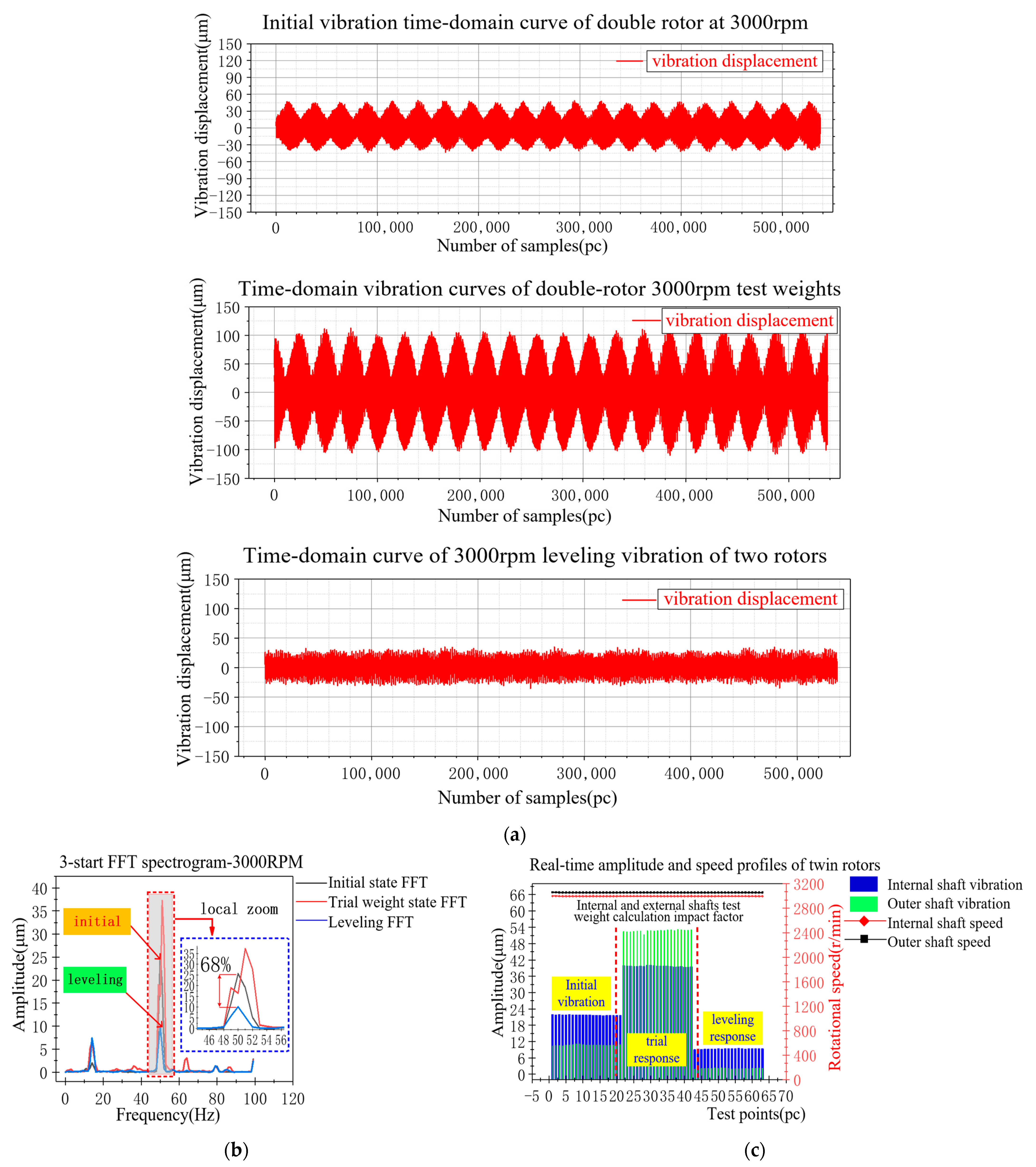
According to the data in the table, the calculated counterweight position in the corresponding positions of the inner and outer rotor counterweight disks was applied to the accurate correction mass. The stand test was started again to observe the changes in the vibration response of the inner and outer rotors, and the specific test process of the sensor was measured, as shown in the vibration response curve in Figure 15. Among them, Figure 15a shows the original vibration displacement time–domain signals measured by the sensors of three starts (initial, test weight and leveling); Figure 15b shows the spectrum corresponding to the fast Fourier transform of the time–domain signals of the three starts; and Figure 15c shows the vibration reduction curves of the dynamic balancing process of both the internal and external rotors, as well as the real-time rotational speed diagrams.
Analyzing the data in Table 10 reveals that, the use of the dual-rotor coupled vibration separation method can accurately and quickly identify the vibration response information of the internal and external rotors, and has good stability at higher speeds; the vibration identification system has a certain degree of robustness, and in the field of vibration faults, generated by mass imbalance in the coaxial dual-rotor structural system, we have achieved a good dynamic balance of the vibration of the active control effect.

6. Conclusions

In this paper, for the aviation power equipment typical twin rotor structure mechanical system, the value of the vibration in the operating conditions exceeds the standard problem, and so the author puts forward a finite element method based on the twin model’s digital dynamic characteristics in the simulation and test, combined with the multi-source technology means. Taking the double rotor structure of the actual open rotor engine as the research object, a dynamically similar digital twin model is established to carry out simulation test research, and a measurement and control platform that realistically simulates the double rotor structure is constructed in parallel to carry out the relevant experimental test verification. The validity and reasonableness of the proposed method is examined by comparing the simulation and measurement results, and the study finally achieves a good vibration reduction effect and has a better engineering application prospect. The proposed method can be focused on the application of typical mechanical equipment to the rotational rigidity of the dual-rotor system dynamic balance test field, as the test speed of a wide range is not limited to the three rotational speed values in the text and can be universally applied to a variety of rotational speed conditions of the dual-rotor dynamic balance test, making it an effective solution vibration suppression problem of the dual-rotor structure in the aerospace field, reducing the operation and maintenance costs of the equipment while improving the stability and safety. Synthesizing the research in this paper, the following conclusions are drawn:
  • Aiming at the typical dual-rotor structure mechanical system of aerospace and civil equipment, the dual-rotor coupled vibration separation algorithm can accurately identify the respective unbalance response information of the inner and outer rotors (a sensor can obtain the vibration information of two rotors), and make technical reserves for the subsequent dual-rotor dynamic balancing;
  • Under the premise of ensuring the accuracy of the model, the calculation results of the finite element twin model in the virtual space can be used to guide the physical reality of the structure of the on-site test, the simulation modeling calculations are basically the same as the results of the real test, and the simulation results of the twin-rotor finite element modeling can be used as a theoretical basis for the actual structural test;
  • Based on the independently designed and constructed simulated dual-rotor test bench, dynamic balancing tests with coaxial counter-rotating dual-plane dual influence coefficients were carried out. Beneficial vibration reduction effects were achieved for both the inner and outer rotors under three typical working conditions, further proving the accuracy of the identification algorithm, which meets the requirements for dynamic balancing accuracy of the equipment and stable operation.
In the subsequent study, the introduction of BP neural network and adaptive particle swarm for the dynamic balancing method is considered to derive the optimal leveling strategy through big data training. In addition, the real-time data interaction between the twin model and the physical entity is improved by the model degradation method, which is a step further in the field of building dynamic digital twin systems. Finally, the automatic balancing method of the dual-rotor system is studied to realize the online real-time suppression of the amount of residual unbalance in the system under the premise of ensuring the equipment does not shut down, so as to help the intelligent development of the equipment with the concept of self-healing.

Author Contributions

Conceptualization, Y.G. and L.C.; methodology, Y.G.; software, Y.L.; validation, Y.G., L.C. and Y.L.; formal analysis, L.C.; investigation, X.Z.; resources, L.C.; data curation, Y.G.; writing—original draft preparation, Y.G.; writing—review and editing, X.Z.; visualization, L.C.; supervision, X.Z.; project administration, L.C.; funding acquisition, L.C. All authors have read and agreed to the published version of the manuscript.

Funding

This research was funded by the National Natural Science Foundation of China, grant number 52375077, 91860126.

Data Availability Statement

Data are contained within the article.

Acknowledgments

The authors sincerely thank the Key Laboratory of Engine Health Monitoring-Control and Networking of Ministry of Education and State Key Laboratory of High-end Compressor and System Technology extended to this study.

Conflicts of Interest

The authors declare no conflicts of interest.

References

  1. Yan, C.Z. Open Rotor Engines; Aviation Industry Press: Beijing, China, 2016. [Google Scholar]
  2. Zhang, Z.X.; Jing, T.; Chen, A.P. Development and research on portable micro-velocity difference double rotor system intelligent whole machine dynamic balancer. J. Vib. Eng. 2003, 16, 62–66. [Google Scholar]
  3. Zhang, Z.X.; Jin, Z.J.; He, S.Z. Research on dynamic balancing method of coaxial micro-speed differential double rotor system. J. Mech. Eng. 2004, 40, 40–44. [Google Scholar] [CrossRef]
  4. Wang, J.; Zuo, Y.F.; Jiang, Z.N.; Feng, K. Evaluation of vibration coupling effects in a two-rotor system with intermediate bearings. J. Aeronaut. 2021, 42, 401–412. [Google Scholar]
  5. Feng, G.Q.; Zhou, B.Z.; Luo, G.H. An analytical approach to the vibration characteristics of a counter-rotating twin-rotor engine. Trans. Nanjing Univ. Aeronaut. Astronaut. 2012, 29, 33–39. [Google Scholar]
  6. Wang, Q.H.; Zhou, L.; Wang, Z.X. Pneumatic design methodology for counter-rotating open rotors. J. Aerodyn. 2024, 39, 138–149. [Google Scholar]
  7. Chen, Z.W.; Jiang, Y.B.; Zhao, Y.; Lu, X.Y.; Tong, F. Wind tunnel test techniques for counter-rotating propeller aerodynamic and aerodynamic noise. J. Aerodyn. 2022, 1–10. [Google Scholar] [CrossRef]
  8. Song, Z.Y.; Hong, J.; Wang, Y.F.; Ma, Y.H. Vibration coupling mechanism and response characteristics of a common support-twin rotor system. J. Aerodyn. 2023, 38, 11. [Google Scholar] [CrossRef]
  9. Wei, G.S. Research on the Analytical Method of Coupled Dynamics of Internal and External Twin Rotor System of Aircraft Development. Master’s Thesis, Dalian University of Technology, Dalian, China, 2019. [Google Scholar]
  10. Tang, Z.H.; Mi, D.; Lu, Y.; Long, L.; Tang, Y. Study on the coupled vibration characteristics of bearing common cavity-twin rotor system. Adv. Technol. 2022, 43, 246–255. [Google Scholar]
  11. Qu, X.X. Research on Blind Separation Technique of Rotor Coupling Fault Vibration Signals. Master’s Thesis, Nanjing University of Aeronautics and Astronautics, Nanjing, China, 2011. [Google Scholar]
  12. Miao, H.; Wang, K.M.; Zhai, X.; Mu, P. Finite element analysis of the dynamic characteristics of a counter-rotating twin-rotor system. J. Shenyang Univ. Aeronaut. Astronaut. 2011, 28, 27–32. [Google Scholar]
  13. Zhang, D.Y.; Liu, Y.H.; Hong, J.; Ma, Y.H. Dynamic modeling and vibration characterization of aero-engine complete machine. Propuls. Technol. 2015, 36, 768–773. [Google Scholar]
  14. Ouyang, Y.F.; Ming, Y. Vibration characterization of aero-engine twin-rotor system with touch-and-go faults. Mech. Eng. 2016, 11, 65–71. [Google Scholar]
  15. Zhang, T.C. Bending-Torsion Coupling Vibration Analysis of Aero-Engine Twin-Rotor System Under Touch-and-Go Failure. Master’s Thesis, Tianjin University, Tianjin, China, 2018. [Google Scholar]
  16. Wang, F.; Luo, G.H.; Cui, H.T. Effect of speed ratio on nonlinear dynamic characteristics of a two-rotor system. J. Nanjing Univ. Aeronaut. Astronaut. 2018, 50, 367–374. [Google Scholar]
  17. Long, L.; Li, J.; Zhao, Y.M.; Wang, D. Coupled vibration characteristics of the power driving shaft-casing system. Sci. Technol. Eng. 2021, 21, 14422–14427. [Google Scholar]
  18. Zhong, W.C.; Wang, Y.; Song, J.; Zhang, H.; Song, J. A novel correction method for aero-engine mathematical models. J. Aerodyn. 2023, 38, 2776–2784. [Google Scholar] [CrossRef]
  19. Wang, N.; Jiang, D.; Xu, H. Dynamic characteristics analysis of a dual-rotor system with inter-shaft bearing. J. Aerosp. Eng. 2019, 233, 1147–1158. [Google Scholar] [CrossRef]
  20. Hai, P.M.; Bonello, P. An impulsive receptance technique for the time domain computation of the vibration of a whole aero-engine model with nonlinear bearings. J. Sound Vib. 2008, 318, 592–605. [Google Scholar] [CrossRef]
  21. Guskov, M.; Sinou, J.-J.; Thouverez, F. Multi-dimensional harmonic balance applied to rotor dynamics. Mech. Res. Commun. 2008, 35, 537–545. [Google Scholar] [CrossRef]
  22. Sun, C.; Chen, Y.; Hou, L. Steady-state response characteristics of a dual-rotor system induced by rub-impact. Nonlinear Dyn. 2016, 86, 91–105. [Google Scholar] [CrossRef]
  23. Hou, L.; Chen, Y.; Fu, Y.; Chen, H.; Lu, Z.; Liu, Z. Application of the HB–AFT method to the primary resonance analysis of a dual-rotor system. Nonlinear Dyn. 2017, 88, 2531–2551. [Google Scholar] [CrossRef]
  24. Pi, J.; Chang, J.Z.; Liu, G.C. Analysis of aero-engine vibration signals. J. Syst. Simul. 2020, 32, 525–532. [Google Scholar]
  25. Zhao, Y.H.; Zhang, H.Y.; Shi, X.Z. An effective vibration signal separation algorithm. Noise Vib. Control. 2002, 22, 13–16. [Google Scholar]
  26. Feng, G.Q.; Zhu, X.G. Vibration characteristics of rotor systems with initial bending. Aeroengine 2003, 1, 20–22. [Google Scholar]
  27. Chen, M.L.; Li, S.M.; Wen, W.D.; Liu, J.Y.; Du, J.J. Multi-source beat vibration analysis methods and tests. Vib. Test Diagn. 2011, 31, 202–206. [Google Scholar]
  28. Bian, B.; Liu, S.Q.; He, S.Y.; Li, D.G. Analysis of beat vibration phenomenon in the electric spindle of magnetic levitation bearing grinding machine. J. Shandong Univ. 2012, 42, 133–142. [Google Scholar]
  29. Zhao, Q.; Jia, M.P.; Huang, Y.G.; Fang, K.R. Analysis of beat frequency in rotating machine vibration. J. Southeast Univ. 2003, 33, 312–315. [Google Scholar]
  30. Ding, X.F.; Liao, M.F.; Cao, H.; Dong, C. Analysis of vibration fluctuation problem caused by multi-source beat vibration in aero-engine. In Proceedings of the Abstracts of the 14th National Vibration Theory and Application Conference, Tianjin, China, 22–24 October 2021; Chinese Society of Vibration Engineering: Nanjing, China, 2021; p. 66. [Google Scholar] [CrossRef]
  31. Xiao, N.; Liu, K. Numerical simulation calculation and test of transient heat transfer in aero-engine heating. China Sci. Technol. Inf. 2022, 1, 38–40. [Google Scholar]
  32. Song, X.P.; Liao, M.F. Separation test technique for vibration signals of twin rotor aero-engine. Mech. Sci. Technol. 2006, 25, 487–490. [Google Scholar]
  33. Liu, X.F. Research on Vibration Signal Separation Technology of Twin Rotor Aero-Engine. Master’s Thesis, Shenyang Institute of Aeronautics and Astronautics, Shenyang, China, 2009. [Google Scholar]
  34. Bai, J.F. Modern Signal Processing Methods and Their Application in Engine Vibration Signal Analysis. Master’s Thesis, Northwestern Polytechnical University, Xi’an, China, 2004. [Google Scholar]
  35. Han, J.; Gao, D.P.; Hu, X.; Chen, G.J. Beat vibration analysis of aero-engine twin rotor system. J. Aeronaut. 2007, 28, 1369–1373. [Google Scholar]
  36. Han, J.; Gao, D.P.; Hu, X. A model-based fault diagnosis method for double rotor imbalance. J. Aerosp. Dyn. 2008, 23, 932–938. [Google Scholar]
  37. Luciano, P.P.; Geraldo, C.; Joao, C.M. Simplified procedure for vibration analysis and dynamic balancing in mechanical systems with beats frequency. Measurement 2021, 174, 109056. [Google Scholar]
  38. Vencl, A.; Gašić, V.; Stojanović, B. Fault tree analysis of most common rolling bearing tribological failures. IOP Conf. Ser. Mater. Sci. Eng. 2017, 174, 012048. [Google Scholar] [CrossRef]
  39. Philip, B.; Pham, M.H. A receptance harmonic balance technique for the computation of the vibration of a whole aero-engine model with nonlinear bearings. J. Sound Vib. 2009, 324, 221–242. [Google Scholar]
  40. Ronny, R.; Volker, D.; Peter, M.; Carsten, S.; Adrian, R. Inverse imbalance reconstruction in rotordynamics. J. Appl. Math. Mech. 2010, 86, 385–399. [Google Scholar]
  41. Sembiring, A.; Lubis, A. Numerical Study for Comparison of Pseudo Modal and Direct Method in Predicting Critical Speed of Coaxial Dual Rotor System. Mater. Sci. Eng. 2020, 990, 012028. [Google Scholar] [CrossRef]
  42. An, S.L.; Jin, W.H.; Dong, H.C. Coupled lateral and torsional vibration characteristics of a speed increasing geared rotor-bearing system. J. Sound Vib. 2003, 263, 725–742. [Google Scholar]
  43. Nandi, A. Reduction of finite element equations for a rotor model on non-isotropic spring support in a rotating frame. Finite Elem. Anal. Des. 2004, 40, 935–952. [Google Scholar] [CrossRef]
  44. Ferraris, G.; Maisonneuve, V.; Lalanne, M. Prediction of The Dynamic Behavior of Non-Symmetric Coaxial Co-Or Counter-Rotating Rotors. J. Sound Vib. 1996, 195, 649–666. [Google Scholar] [CrossRef]
  45. Su, S.K.; Lv, L. ANSYS Finite Element Structural Analysis and Example Analysis; Chemical Industry Press: Beijing, China, 2014. [Google Scholar]
  46. Yang, J.; Zhou, B.T. Study on the vibration signal separation method of micro-velocity difference double rotor system. China Mech. Eng. 2002, 8, 86–89+6. [Google Scholar]
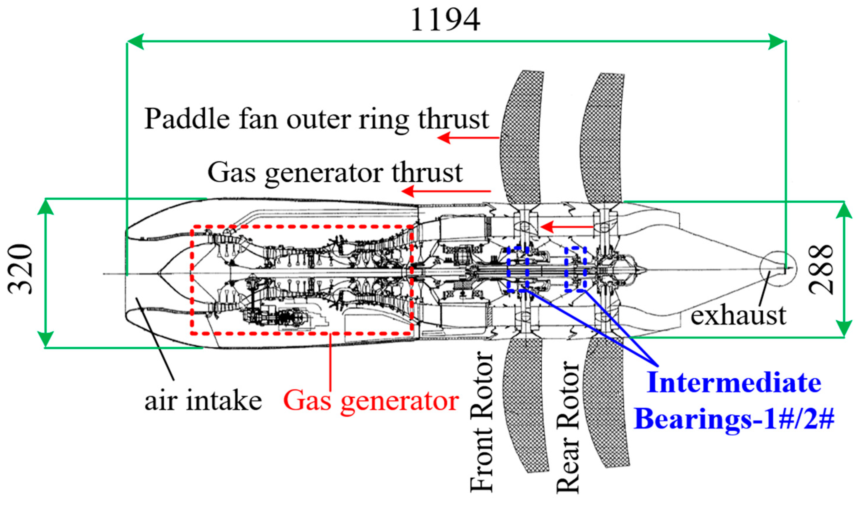
Figure 1. Double-row counter-rotating open rotor engine structure schematic.
Machines 12 00391 g001
Figure 2. Structural design and mechanical model of simulated dual rotor test stand. 1#, 2#: Intermediary bearings; D1, D2: Outer rotor counterweight plate; D3, D4: Internal rotor weight plate; L1–8: Dimensional data of internal and external rotor mechanism; (1), (4): Inner rotor left and right support; (2), (3): Intermediate bearing support.
Machines 12 00391 g002
Figure 3. Simulation of a two-rotor finite element discrete model.
Machines 12 00391 g003
Figure 4. Simulation of the first four orders of modal vibrations of a double rotor.
Machines 12 00391 g004
Figure 5. Simulation of open double rotor structure schematic.
Machines 12 00391 g005
Figure 6. Finite element calculation results of modal simulation of double rotor structure. (a) Calculation of natural frequency and deformation of the first four orders of modes; (b) Campbell diagram calculation of critical speed for double rotor structure [44].
Machines 12 00391 g006aMachines 12 00391 g006b
Figure 7. Simulated two-rotor simulation test vibration suppression data plot.
Machines 12 00391 g007
Figure 8. Double rotor beat vibration waveform and envelope.
Machines 12 00391 g008
Figure 9. Schematic diagram of double rotor vibration response identification under micro-frequency difference.
Machines 12 00391 g009
Figure 10. Schematic diagram of four typical beat vibration waveforms of double rotor.
Machines 12 00391 g010
Figure 11. Schematic diagram of open rotor simulation test platform architecture. (a) Simulation of double rotor dynamic balancing test bench physical picture; (b) Double rotor dynamic balancing test upper computer control software and data acquisition system.
Machines 12 00391 g011
Figure 12. Schematic diagram of inner and outer axle steering and counterweight disk position.
Machines 12 00391 g012
Figure 13. Simulation of open rotor vibration test and dynamic balancing results-1000 rpm. (a) The original vibration displacement signal mapping of the 3 starts measurements; (b) 3 starts Fourier transform spectrum curve; (c) Measured speed of internal and external rotors and vibration reduction curve of dynamic balancing.
Machines 12 00391 g013
Figure 14. Simulation of open rotor vibration test and dynamic balancing results-850 rpm. (a) The original vibration displacement signal mapping of the 3 starts measurements; (b) 3 starts Fourier transform frequency–domain plot; (c) Measured speed of internal and external rotors and vibration reduction curve of dynamic balancing.
Machines 12 00391 g014
Figure 15. Simulation of open rotor vibration test and dynamic balancing results-3000 rpm. (a) The original vibration displacement signal mapping of the 3 starts measurements; (b) 3 starts Fourier transform frequency–domain plot; (c) Measured speed of internal and external rotor and vibration reduction diagram of dynamic balancing.
Machines 12 00391 g015
Table 1. Double rotor test bench structure parameters.
Parameter
Meaning
SymbolicDimensions/(mm)
1 fulcrum-D1L1119
2 fulcrum-D2L263
1 fulcrum-
2 fulcrum
L3138
2 fulcrum-
3 fulcrum
L4202
1 fulcrum-
4 fulcrum
L5536
D3–D4L656
D4-4 fulcrumL743
D1–D2L882
Table 2. Table of empirical bearing parameters.
Pivot Stiffness1 Fulcrum2 Fulcrum3 Fulcrum4 Fulcrum
Kxx/(N·mm−1)1.00 × 1042.00 × 1052.00 × 1051.00 × 104
Kyy/(N·mm−1)1.00 × 1042.00 × 1052.00 × 1051.00 × 104
Table 3. Double rotor disk unit parameter table.
Disk UnitNodal
Position
Disk Mass/kgDiameter Inertia/(kg·m2)Polar Moment of Inertia/(kg·m2)
Disk12912.340.1320.2572
Disk2231.310.0050.0106
Disk3612.250.1310.2548
Disk441.690.0050.0109
Table 4. Eddy current vibration sensor parameter table.
Model NumberProbe SizeRangeMidpoint
Voltage
SensitivityPower Supply Voltage
ZA-218 mm2 mm−10 V8 mV/μm−24 V
Table 5. 1000 RPM Dual Rotor Test Data Sheet.
1000 rpm
Experimental
Test WeightsMeasured Rotor
Response
Amplitude
(μm)
Phase (°)Impact FactorLag AngleCounterweight Position
internal shaft57.67 ginitial
response
28.70212.700.85 μm/g33.38 g
∠−45.00°test weight response23.7070.80∠94.90°∠−62.00°
outer shaft67.57 ginitial
response
7.4058.600.49 μm/g15.06 g
∠30.00°test weight response39.3031.40∠−4.40°∠−117.00°
Note: Inner rotor—1000 RPM, outer rotor—1060 RPM, speed difference Δn = 1 Hz (60 RPM).
Table 6. Comparison table of data before and after dynamic balancing of internal and external rotors.
Internal Shaft: 1000 rpm
Outer Shaft:
1060 rpm
Initial
Vibration
Leveling
Vibration
Percentage
of Vibration
Reduction
inner rotor28.52 μm3.93 μm86.20%
outer rotor7.47 μm1.26 μm83.10%
Table 7. 850 RPM Dual Rotor Test Data Sheet.
850 rpm
Experimental
Test WeightsMeasured Rotor
Response
Amplitude
(μm)
Phase (°)Impact FactorLag AngleCounterweight Position
internal shaft78.19 ginitial
Response
27.70216.300.88 μm/g31.56 g
∠30.00°test weight Response63.50127.70∠73.90°∠−38.00°
outer shaft108.18 ginitial
Response
8.9060.900.61 μm/g15.08 g
∠45.00°test weight Response72.5035.20∠−13.30°∠−106.00°
Note: Inner rotor—800 RPM, outer rotor—860 RPM, speed difference Δn = 1 Hz (60 RPM).
Table 8. Comparison table of data before and after dynamic balancing of internal and external rotors.
Internal Shaft: 800 rpm
Outer Shaft:
860 rpm
Initial
Vibration
Leveling
Vibration
Percentage
of Vibration
Reduction
inner rotor27.53 μm18.21 μm33.90%
outer rotor8.57 μm1.46 μm82.90%
Table 9. 3000 RPM Dual Rotor Test Data Sheet.
3000 rpm
Experimental
Test WeightsMeasured Rotor
Response
Amplitude
(μm)
Phase (°)Impact FactorLag AngleCounterweight Position
internal shaft17.06 ginitial
response
21.70226.502.41 μm/g9.02 g
∠45.00°test weight response39.20147.30∠70.90°∠−24.00°
outer shaft27.12 ginitial
response
11.1072.101.59 μm/g6.94 g
∠30.00°test weight response53.2092.20∠67.30°∠−175.00°
Note: Inner rotor–3000 RPM, outer rotor–3060 RPM, speed difference Δn = 1 Hz (60 RPM).
Table 10. Comparison table of data before and after dynamic balancing of internal and external rotors.
Internal Shaft:
3000 rpm
Outer Shaft:
3060 rpm
Initial
Vibration
Leveling
Vibration
Percentage
of Vibration
Reduction
inner rotor21.94 μm9.47 μm56.80%
outer rotor10.78 μm1.94 μm82.10%
Disclaimer/Publisher’s Note: The statements, opinions and data contained in all publications are solely those of the individual author(s) and contributor(s) and not of MDPI and/or the editor(s). MDPI and/or the editor(s) disclaim responsibility for any injury to people or property resulting from any ideas, methods, instructions or products referred to in the content.