Abstract
Robotic manipulators are critical for industrial automation, boosting productivity, quality, and safety in various production applications. Key factors like the payload, speed, accuracy, and reach define robot performance. Optimizing these factors is crucial for future robot applications across diverse fields. While 6-Degrees-of-Freedom (DoF)-articulated robots are popular due to their diverse applications, this research proposes a novel 5-DoF robot design for industrial automation, featuring a combination of three prismatic and two revolute (2R) joints, and analyzes its workspace. The proposed techno-economically efficient design offers control over the robot manipulator to achieve any reachable position and orientation within its workspace, replacing traditional 6-DoF robots. The kinematic model integrates both parallel and serial manipulator principles, combining a Cartesian mechanism with rotational mechanisms. Simulations demonstrate the end effector’s flexibility for tasks like welding, additive manufacturing, and material inspections, achieving the desired position and orientation. The research encompasses the design of linear and rotational actuators, kinematic modeling, Human–Machine Interface (HMI) development, and welding application integration. The developed robot demonstrates a superior performance and user-friendliness in welding. The experimental work validates the design’s optimized joint trajectories, efficient power usage, singularity avoidance, easy access in application areas, and reduced costs due to fewer actuators.
Keywords:
trajectory; optimization; forward kinematic; inverse kinematic; singularity; orientation; actuators 1. Introduction
The digital era necessitates robotic automation, which utilizes intelligent automation technologies to streamline processes and execute tasks according to predetermined programs, thus automating the process. The adoption of robotic process automation fosters significant increases in productivity and efficiency across various sectors. Industrial manufacturing is a prime example where robotic process automation has become nearly indispensable. By automating tasks like material handling, painting, assembly, packing, and welding, robots have revolutionized manufacturing methods, expanding the potential for efficiency and productivity. These advantages empower automation industries to produce high-quality products at increased output levels. Furthermore, robotic adoption drives innovation, moving robots from research and development to real-world applications. This fosters a new era of human–machine collaboration and intelligent business process automation. It achieves cost reduction by minimizing or replacing manual labor in repetitive, cumbersome, and error-prone tasks. Additionally, the precision and reliability of robotic manipulators make them invaluable assets for identifying and handling abnormal situations where accuracy and repeatability are absolute necessities.
The rapid development of cutting-edge technologies has led to significant advancements in automated welding manufacturing, which has been effectively utilized in production facilities across various industries in recent years. These industries include automobiles, the construction of steel bridges, machinery, and metal products, etc. The adoption of robotic welding facilitates a shift from manual to automated processes, improving production rates through high-speed manipulation and enhancing product quality by achieving smooth and precise weld trajectories [1,2]. However, overcoming challenges in the production line welding process requires significant improvements. These improvements include increased welding torch flexibility, optimized trajectories to avoid singularities, ensured energy efficiency, and user-friendly operations—all achievable through the use of suitable robotic manipulators [3]. Thus, the automated welding manufacturing process demands techno-economic solutions. This necessitates a deep understanding of several key aspects:
- The robot’s optimal mechanism design.
- Kinematic models for precise robot movement.
- Efficient manipulation strategies.
- User-friendly human–machine interfaces for ease of operation.
- The integration of an efficient control system.
Developing high-performance robotic welding applications requires not only implementing various methodologies, but also utilizing robots with more than six degrees of freedom (DoF) to tackle complex tasks. However, robots with multiple rotational manipulators, while offering flexibility, present limitations. Their intricate structure makes programming and control more challenging [4]. Achieving efficient control for robots with redundant kinematic models is a complex task. Fortunately, optimized control schemes based on these redundant models can improve both the power and efficiency of robot control systems [5]. Also, considering DoF and singularity (a configuration where movement becomes impossible), it is important to note that in 6-DoF-articulated robots, the last three axes are typically used to control the orientation of the end effector (tool). Alternatively, two DoF revolute joint manipulators offer greater flexibility in orientation and minimize the risk of singularities during downward welding trajectories [6].
The future of robotic manipulators emphasizes innovation in design and functionality. A major focus is the development of manipulators with flexible structures, allowing for greater dexterity and adaptation in complex environments, which is especially beneficial for intricate tasks. Additionally, smoother trajectory planning is crucial. By optimizing movement paths, robots become easier for control systems to track, ultimately improving the overall performance. Finally, minimizing power consumption and actuation forces is a key objective. This can be achieved by reducing the forces required to move the manipulator (actuation forces) as well as optimizing the trajectory paths for efficiency [7,8,9].
The trajectory planning process plays a critical role in robotic welding. It ensures that the rotational angles of each joint are adjusted precisely along a predefined path as the robot moves from one point to another, ultimately reaching the target position. The robot’s path points are calculated in the robot controller using inverse kinematics and then converted from the Cartesian space (X, Y, and Z coordinates) to a joint coordinate space (joint angles). Achieving optimal joint configurations is crucial for efficient and smooth welding. This is often achieved through the integration of different mechanisms like prismatic joints (linear motion) and revolute joints (rotational motion). These mechanisms work together to create an optimal trajectory path with efficient tool orientation for welding [10,11]. Cartesian robots typically have linear prismatic mechanisms on each axis, allowing them to move independently with high accuracy and repeatability. This linear design simplifies control movements and enables them to operate in a wide range of positions within their workspace. An additional benefit of prismatic mechanisms is their lower friction, leading to lower energy consumption during operation. They also provide stability support for the manipulator’s structure [12].
This research focuses on designing and developing a robotic manipulator optimized for welding applications. The goal is to create an efficient trajectory motion, user-friendly, power consumption, and cost-effective solution. The motivation stems from the development of a 5-DoF (Degree-of-Freedom) hybrid robot for industrial automation, featuring a three Prismatic and two Revolute (3P2R) manipulator design. This optimized design aims to replace the prevalent use of 6-DoF robots for improved welding efficiency.
The proposed methods for enhancing trajectory planning include minimizing the trajectory length and reducing the number of DoF required to reach the desired target position. To reduce the execution time and maximize robot productivity, we consider the inherent limitations in the relative speeds of the actuator components. Trajectory path analysis and power evaluation experiments demonstrate that the proposed mechanism provides an effective trajectory workspace. This research introduces a design that can achieve a broad range of positions, a remarkable motion range, flexibility, power optimization, and efficient task navigation within its workspace. The proposed design makes it well-suited for other applications such as additive manufacturing and material inspections, apart from welding applications, showcasing a good overall performance.
1.1. Scope and Contributions
The industrial manufacturing sector craves advanced technologies that can reduce both maintenance and investment costs, alleviating challenges faced in automating various industries like medical equipment, shipbuilding, and aerospace. Overcoming these hurdles hinges on applying suitable methodologies for manipulator development, where trajectory planning and control are crucial. For a robotic manipulator to precisely follow a planned path (trajectory), it relies on servomotors to apply force at its joints. To accurately describe the manipulator’s motion, we need both kinematic and dynamic analyses.
This research delves into the optimal design of robotic manipulators using prismatic and revolute mechanisms. By analyzing forward and inverse kinematics, along with singularity avoidance, the project paves the way for efficient modeling and design in future applications. Optimizing these fundamental mechanisms prioritizes a large singularity-free workspace and superior kinematic performance. The success of this integrated design extends beyond welding, demonstrating its utility in machine assembly, material handling, inspection, and even the medical field. This research contributes to advancements in these areas by offering benefits such as optimized joint trajectories, minimized joint usage, improved power efficiency, precise positioning, and enhanced welding parameter control.
1.2. Organization of the Work
This paper is organized as follows:
Kinematic Modeling and Design
Section 2 details the kinematic modeling of the proposed 3P2R robot using Denavit–Hartenberg (D-H) parameters. This section covers both forward and inverse kinematics, with the algorithms evaluated through MATLAB R2023a simulations. Section 3 delves into the meticulous design and construction of the manipulator itself. It details the creation of a three-axis prismatic manipulator and a two-axis revolute wrist, carefully assembled to form a hybrid robotic manipulator.
Integration and Control
Section 4 focuses on system integration. It describes how the manipulator seamlessly integrates with a welding setup, ensuring the synchronized movement of each joint for efficient robotic operation. Additionally, a Human–Machine Interface (HMI) is created to facilitate user control over welding applications.
Performance Evaluation
Section 5 details the performance evaluation of the developed system. Here, comprehensive experimental tests are conducted across various welding applications, comparing results to the standard articulated robot trajectory motion. The experiments demonstrate the advantages of the new system, including an effective trajectory motion, reduced power consumption, and the ability to avoid the singularity positions.
2. Design Consideration and Kinematic Modeling
This development considers various industrial welding applications through a comprehensive literature review on manipulator motions. For a robotic arm to position and orient the end effector (tool) precisely during welding, two key aspects are considered:
- Positional Control: the first three joints of an articulated robot manage its position (X, Y, and Z axes).
- Tool Orientation: the last three joints of an articulated robot, or the last two joints in this case, provide rotational freedom for tool orientation (typically achieved with a “wrist”).
The proposed 5-DoF robot leverages this concept. The first three linear joints (Lx, Ly, and Lz) control the robot’s position along the X, Y, and Z axes, respectively. The kinematic modeling of the developed 5-DoF robot is shown in Figure 1. The last two rotary joints (θrot and θtilt) represent the rotational axes (R-axis) and tilting axis (T-axis) of the “wrist,” allowing for precise tool orientation during welding tasks. Los and Lt are defined as the link offset and tool length.
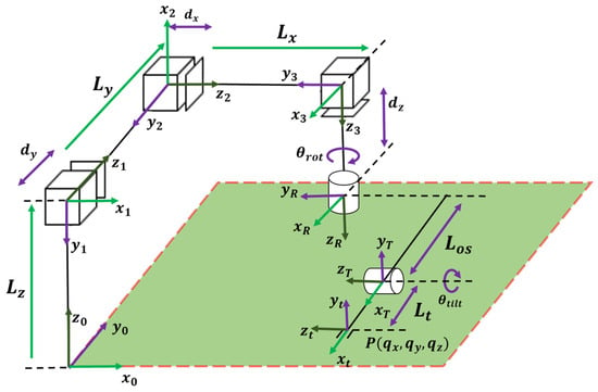
Figure 1.
The kinematic representation of 5 DoF robot.
Developing a precise kinematic model is essential for controlling robotic arms and achieving an optimal performance. Kinematic algorithms serve a vital role in allowing us to calculate the robot’s position (translation) and convert between joint angles and real-world coordinates (Cartesian coordinates) [13,14,15]. The proposed robotic system incorporates these algorithms with additional features specifically designed for welding applications. This not only enhances functionality, but also addresses limitations found in existing systems. The modular design allows for customizations to meet specific welding needs. The relationship between Cartesian and prismatic manipulators and their integrated mobility is established through robot kinematic analysis [16]. This analysis relies on two key formulas: forward and inverse kinematics. Forward kinematics calculates the end effector’s position based on the current joint angles, while inverse kinematics determines the necessary joint angles to reach a desired end-effector position. By leveraging these principles, the robotic system can perform welding tasks with high precision and efficiency. In essence, the kinematic model serves as the foundation for optimizing the performance and achieving desired outcomes across various industrial applications.
The representation of the forward and inverse kinematics of the robotic manipulator adheres to the Denavit–Hartenberg parameters and matrices methodology. The Denavit–Hartenberg parameters consist of a set of four parameters for each joint of the 5-DoF robot, and serving to define the geometry and spatial relationships between consecutive links in the robotic manipulator, is the Transformation Matrix representing the present state (i) from the previous state (i − 1).
Here,
R(z,θi)—Rotational Matrix, the joint angle θi about the z-axis;
T(z,di)—Translation Matrix, the link offset di along the z-axis;
R(x,αi)—Rotational Matrix, the link twist αi about the x-axis;
T(x,ai)—Translation Matrix, the link length ai along the x-axis.
The Denavit–Hartenberg standards incorporate the products of four fundamental transformations to describe the homogeneous transformation matrix used to determine each joint transformation matrix. The reference frame of the kinematic model is represented as a reference frame translated to a tool frame in a manner analogous to the depiction of each translation illustrated in Figure 1. The configuration process involves considering the total kinematic model of the proposed robotic manipulator and determining the Denavit–Hartenberg parameters, as shown in Table 1.

Table 1.
Representation of Denavit–Hartenberg parameters for five-axis manipulators.
2.1. Forward Kinematic Analysis
Forward kinematics is a method utilized in robotics to determine the position of the tool within the workspace based on the movements of all the joints comprising the robotic arm. In this process, each joint of the robot has a reference frame known as the joint frame. The joint frames involve sequentially applying the transformations associated with each joint’s motion to determine the final position and orientation of the end effector within the workspace. In essence, forward kinematics allows us to track the movement of the end effector as each joint of the robot arm changes position. The proposed kinematic model uses a Homogeneous Transformation Matrix to organize fixed and variable elements, describing the relationship between coordinate systems. This unified representation allows precise control over the tool’s spatial relationship, facilitating accurate robotic operations.
Equations (2)–(4) represents the Homogeneous Transformation Matrix for three prismatic joints’ position and orientation. The integrated R-axis, T-axis, and tool end effector, denoted as the 2R-Wrist’s position and orientation, have been calculated from the product of both axis transformation matrices which are defined as Equations (5)–(7). Here, cosθrot = Cr, sinθrot = Sr, cosθtilt = Ct, and sinθtilt = St.
The tool position is determined by the Total Transformation Matrix of the integrated cartesian and 2R-wrist has been computed as .
The resultant total transformation matrix is used to identify the tool’s position and orientation. The tool end-effector location is represented by the final column of the Total Transformation Matrix and the orientation is represented by the first three columns of the matrix.
This position is represented by its x, y, and z coordinates, denoted as qx, qy, and qz in (8a), (8b), and (8c), respectively. The tool’s orientation is represented by θx and θz in (8d) and (8e), respectively. The computation of forward kinematics involves determining the positions of the Cartesian manipulator joints and 2R-Wrist joint, resulting in the location and orientation of the end-effector tool.
2.2. Inverse Kinematic Analysis
Unlike forward kinematics which calculates the end-effector position based on joint angles, inverse kinematics works the other way around. It determines the specific joint angles the robot needs to reach a desired end-effector position. This is particularly important for robots with multiple joints, like articulated robots, where there can be several combinations of joint positions to reach the same target location [17,18].
The robot offers an efficient solution for determining the actual position of each joint based on the tool’s Cartesian coordinates using basic trigonometric functions [19]. This is achieved by integrating Cartesian control, which allows for generating a single, optimized set of joint values. This optimized set is crucial for effective path planning across the robot’s entire workspace. Figure 2a shows the schematic representation of the 2R-Wrist in the Three-Dimensional (3D) plane. Figure 2b shows the Schematic representation of the 2R-Wrist in the XY plane. The ∆x, ∆y, and ∆z values can be utilized to determine the position of the 2R-Wrist using the available variables θ1, θ2, and Los. Figure 2c shows the schematic representation of the tilting manipulator in the tool frame.
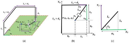
Figure 2.
(a) Schematic representation of the 2R-Wrist in 3D plane, (b) schematic representation of the 2R-Wrist in XY plane, and (c) schematic representation of the tilting frame.
The 2R-Wrist coordinate position denotes ∆x, ∆y, and ∆z. The summation of the 2R-manipulator position and cartesian manipulator joints position is denoted as the actual end-effector tool which is expressed while determining the inverse kinematic solution.
The individual prismatic joint positions (Lx, Ly, and Lz) were determined from the actual position of the tool (qx, qy, and qz) and the 2R-wrist manipulator position (∆x, ∆y, and ∆z) for the inverse kinematic evaluation. As per, the schematic representation of the tool orientation has denoted the revolute manipulator position θrot and θtilt has been directly equated with the given tool orientation with the x-plane and z-plane of the robot workspace, respectively. The analysis of the inverse kinematics describes the mapping from a global position to the joint trajectory, allowing the model to generate the trajectory path from one point to another, thereby creating a suitable trajectory.
Figure 3 showcases a simulation of the 5-DoF robot’s motion trajectory. This simulation utilizes both forward and inverse kinematics algorithms implemented with the MATLAB’s Robotics Toolbox [19]. By analyzing the manipulator’s trajectory under varying Denavit–Hartenberg parameters, the simulation provides valuable insights. These insights include the end-effector’s toolpath, the identification of singularity positions (where movement becomes impossible), and overall efficiency for welding automation. This knowledge allows for optimizing trajectory planning and avoiding problematic configurations in the predefined path. Notably, the integration of parallel and serial manipulator elements within the hybrid kinematic model contributes to this efficiency [20]. While a 6-DoF robot offers complete freedom in choosing the end-effector’s orientation (including roll, pitch, and yaw), the proposed 5-DoF design prioritizes different advantages. Its motion capability is analyzed using the Jacobian matrix and experimentally evaluated for joint mobility. This design offers flexibility in achieving desired trajectories, but may have limitations depending on the specific weld geometry.
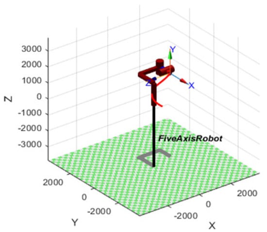
Figure 3.
The simulation of 5-DoF robot trajectory using forward and Inverse Kinematics algorithms.
Furthermore, a key advantage of the three-DoF prismatic manipulators is their ability to achieve singularity-free motion throughout their entire workspace, from start to finish. The attached two-DoF revolute manipulators also offer singularity-free motion in a downward direction. However, their upward orientation may have limitations, which might not be a significant drawback for additive manufacturing and welding applications. It is important to emphasize that the robot’s capabilities are evaluated within the context of its intended use. While it offers advantages like singularity-free motion in key areas, there might be limitations in specific welding tasks that require a wider range of upward orientations.
3. Five-Axis Manipulator Design
Designing a robotic manipulator involves a delicate balance between several factors to ensure optimal performance, reliability, and safety. These key considerations include:
- Stiffness: the robot’s ability to resist deformation under load, which is crucial for precision.
- Motion Stability: smooth and controlled movement, minimizing vibrations and ensuring accuracy.
- Flexibility: the ability to adapt to various tasks and environments effectively.
- End-Effector Mass and Payload: the maximum weight the robot can handle, impacting functionality.
- Material Selection: strength, durability, and heat resistance are vital for welding robots.
The robotic manipulator design must strike a balance between these factors to ensure optimal performance across diverse operational conditions. Careful consideration during the design phase allows engineers to develop robust and reliable systems tailored to specific applications, like industrial welding, while minimizing risks and maximizing efficiency [21,22,23,24,25,26].
This research presents a 5-DoF robot specifically designed for high-accuracy, tabletop-sized industrial welding applications. The system prioritizes safety, complying with all industry standards. This includes emergency switches, joint limit safeguards, welding parameter control, and pre-job safety checks. The design integrates three prismatic and two revolute joint mechanisms, offering a high degree of flexibility while achieving precise positioning and orientation. This optimized configuration allows for smooth and controlled motions during welding tasks.
Joint torque analysis is a crucial aspect of this design. It determines the torque required at each joint to handle the welding tool and consumables, guiding the selection of appropriate motors and gear reduction systems. By optimizing the joint torque, engineers can ensure smooth movement and precise position control throughout the welding process. The detailed mechanical design specifications are outlined in Table 2.

Table 2.
Specifications of the 5-DoF robot.
3.1. Three-Axis Cartesian Joint Design
The core of this robot is the cartesian mechanism, responsible for precise linear movement in the X, Y, and Z directions. This mechanism utilizes several components:
- Servo motors: these provide the driving force for the linear movement.
- Ball screws: these convert the rotary motion of the servo motors into smooth, linear motion.
- Linear guideways: these ensure smooth and accurate movement along the designated axis.
- Gear reduction systems: these adjust the speed and torque output of the servo motors to meet specific application needs.
- Assembling parts: these connect all the components to create a functional unit.
The Z-axis manipulator is mounted vertically, while the X and Y axes are positioned horizontally. This design is optimized for high-precision and repeatable movements, crucial for welding tasks. The selection of appropriate servo motors, ball screws, and gearboxes ensures efficient linear motions, achieving the desired application speed and weld quality. Figure 4 showcases the CAD model of this mechanism, with each component labeled accordingly: (a) the Y-axis prismatic joint, (b) the X-axis prismatic joint, (c) the Z-axis prismatic joint, (d) the R-axis revolute joint, and (e) the T-axis revolute joint, respectively.
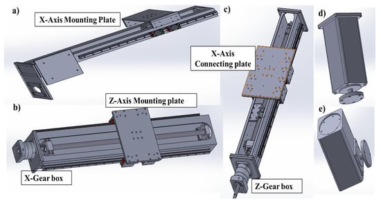
Figure 4.
The manipulator’s CAD Modeling, (a) Y-axis prismatic joint, (b) X-axis prismatic joint, (c) Z-axis prismatic joint, (d) R-axis revolute joint, and (e) T-axis revolute Joint.
The first rotary joint of the “2R” wrist unit is attached at the base of the Z-axis linear actuator. This Z-axis movement is supported by a sturdy double-column beam structure. The same beam structure also provides a movable mounting plate for the X-axis linear actuator. This allows for the precise positioning of the X-axis, which is then mounted on one side of the Y-axis actuator.
3.2. The 2R-Wrist Joint Design
This design prioritizes the flexible control of both the position and orientation, making it ideal for welding applications that demand precise maneuverability. The end effector can move seamlessly across its entire range of motion, ensuring thorough coverage and accurate welds [27,28,29,30]. This flexibility is achieved through a “2R-joint configuration” featuring two revolute actuators that enable both the rotation and tilting of the end-effector tool. Positioned at a 90-degree twist, the R-axis and T-axis actuators provide the necessary movement capabilities. The 2R rotating joint axis, running parallel to the Z-axis, is affixed at its base. Each revolute actuator utilizes servo motors paired with gear reduction systems for high-precision control. The final joint features a customizable end-effector arrangement, allowing for various applications depending on specific tool mounting needs. This adaptability enhances the system’s versatility and utility across different welding tasks.
One notable advantage of this system is its efficient workspace usage. With the entire manipulator supported at one end, the table is left free to accommodate a wide range of welding jobs. This configuration not only maximizes workspace efficiency, but also simplifies maintenance and service procedures, contributing to overall operational ease and productivity.
4. Robot Control System for Welding Applications
The proposed welding robot system comprises three main components: the ABB NextMove e100 motion controller, Bangalore, India, the KempArc Pulse 450 welding power source, Coimbatore, India, and the eSMART10 Human–Machine Interface (HMI) device from Chennai, India. Both forward and inverse kinematics computations are performed within the robot motion controller. The kinematic algorithm translates the positional data input from the pendant into corresponding joint positions. Through closed-loop communication, the controller’s digital pulse interacts with the Servo Drive system. Figure 5 illustrates the control architecture, including details of the drive system, servo motors, and the actuated manipulator. This entire setup facilitates efficient welding operations by providing precise control over the robot’s movements.
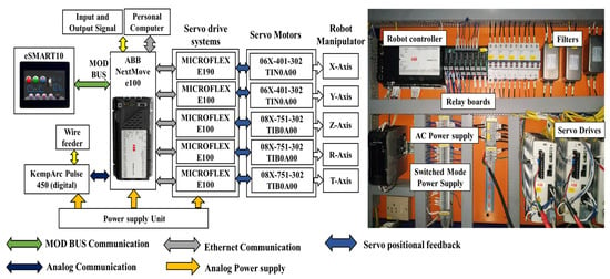
Figure 5.
The Robot Control Panel and its Architecture for Welding Applications.
The HMI features two main operating modes: the JOG mode for individual joint control and the ABSOLUTE mode for specifying exact locations of the welding tool. Additionally, the HMI allows for setting and controlling welding parameters directly, streamlining the process for operators. Furthermore, the HMI offers various profile screens for standard shapes like linear, circular, rectangular, and triangular. This simplifies setting up welding programs for different workpieces. Figure 6 showcases the HMI screen designed specifically for this 5-DoF welding robot. The user-friendly design prioritizes the efficient human–robot interaction. Operators can control the robot’s motion, monitor the system status, and choose between automatic or manual operation modes. This comprehensive interface enhances operator convenience and productivity.
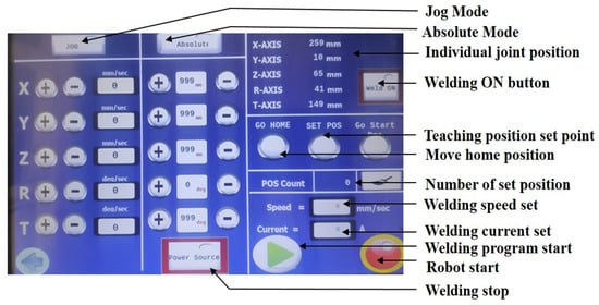
Figure 6.
The 5-DoF robot HMI for welding applications.
The robotic motion controller receives position control commands, which instruct the robot on how to move its tool in synchronization with the desired trajectory to reach the intended target position accurately [31]. The optimal computation of the welding robot’s trajectory is essential to ensure correct torch alignment, seamless robot movement along the weld path, and enhanced positional precision. This goal can be accomplished by minimizing both kinematic and dynamic fluctuations in the robot’s joints, while also controlling welding parameters to ensure high-quality welds. Additionally, the trajectory planning for the robot’s tool should aim to minimize time while maintaining productivity levels [32,33,34]. The proposed control system integrates an additional algorithm for trajectory following, designed to calculate tool trajectory waypoints for manipulating along standard-shaped profile paths. In welding applications, this algorithm enables the welding torch to follow a predefined path based on input parameters provided by the operator, generating wave points along the trajectory. Essential parameters for welding with trajectory paths include the profile shape, dimensions, starting point, tool velocity, and welding parameters.
As an example, the trajectory algorithm can be used for creating circular weld paths with specific angles. Here, ‘r’ represents the radius of the circle and ‘Lt’ refers to the length of the welding tool, which usually remains constant within the program. Figure 7 visually depicts how the tool manipulates along a circular path. The waypoints guiding this movement are determined through trigonometric computation methods.
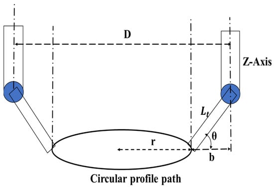
Figure 7.
The visual depiction illustrates the manipulation of the tool along a circular trajectory path.
In Figure 7, ‘D’ represents the diameter of the Z-manipulator joint motion path, while ‘θw’ denotes the weld angle specified by the operators according to their requirements.
The optional parameters ‘r’ and ‘θw’ determine the desired trajectory of the robot’s tool. The Z-manipulator remains constant from the operator’s initial teaching point.
Equations (15)–(17) describe the positions of the X-axis, Y-axis, and R-axis manipulations, respectively, based on the variation of θ(t) from 0 to 360° over time. The rotational axis position directly corresponds to the value of θ(t). These equations are programmed into the robot’s main controller, providing trajectory waypoints for the entire manipulator operation. Variable parameters are inputted through a Human–Machine Interface Device (HMI), processed, and used to generate the desired tool trajectory. Figure 8 shows the trajectory control flow chart of the developed robot. The welding process is facilitated by a power source controller, which configures welding parameters via the HMI. This device also enables the control and monitoring of the robot tool’s position, orientation, and speed data.

Figure 8.
The trajectory control flow chart of the 5-DoF robot.
Figure 9 illustrates a 5-DoF robot equipped for welding tasks. The combination of the motion controller and welding controller facilitates the precise linear movements of the robot while simultaneously controlling the welding parameters. This integrated approach contributes to the improved welding quality.
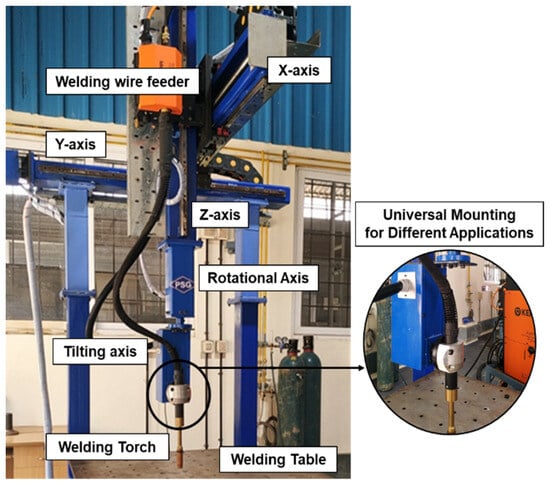
Figure 9.
The 5-DoF robot for welding applications.
In industrial welding processes, prioritizing safety measures is paramount to prevent accidents and mitigate hazardous conditions. Establishing a safe working environment involves implementing advanced sensors, safety interlock programs, emergency alarms, and robotic cells. These safety features not only help in avoiding unwanted incidents, but also foster a harmonious relationship between robots and humans. By incorporating such measures, potential risks are minimized, creating a workspace where both humans and robots can operate efficiently and safely. Figure 10 shows the 5-DoF robot’s functional flow chart for the welding applications. Table 3 contains the details of the performance characteristics of the 5-DoF- and 6-DoF-articulated robot.
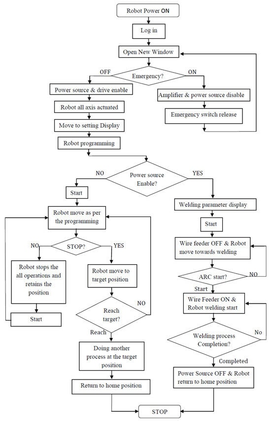
Figure 10.
The 5-DoF robot functional flow chart.

Table 3.
Performance analysis of the 5-DoF- and 6-DoF-articulated robot.
The 3P2R robot excels in simplicity, precision, flexibility, and ease of maintenance, making it ideal for tasks requiring high accuracy in confined spaces for welding application. These capacities are proved by the following experimental process.
5. Results and Discussion
The developed 5-DoF robot’s motion performance was evaluated by performing linear welding tests. These tests involved both rectangular and circular movements. The tests were conducted on both the 5-DoF- and a 6-DoF-articulated robot for comparison purposes. The individual joint motion performance of each robot was analyzed.
The experimental results were then used to calculate the power consumption and the number of rotations required in each joint to achieve the desired target position.
5.1. Rectangular Path Trajectory Experiment
To assess the 5-DoF robot’s performance, a rectangular welding path was chosen. During this test, each joint movement was meticulously evaluated. The robot’s X- and Y-axis actuators were precisely aligned with the frame of the workpiece. Notably, maintaining a 30° orientation throughout the profile motions on each rectangular face proved advantageous for achieving optimal weld penetration.
To achieve the desired rectangular path, the rotational position of each actuator was plotted over time, creating an angle-to-time relationship graph. This graph revealed that the vertical and angular actuators required minimal rotation to execute the trajectory effectively, remaining relatively static. Figure 11 depicts the trajectory displacement of each axis of the 5-DoF robot over time during this rectangular motion.
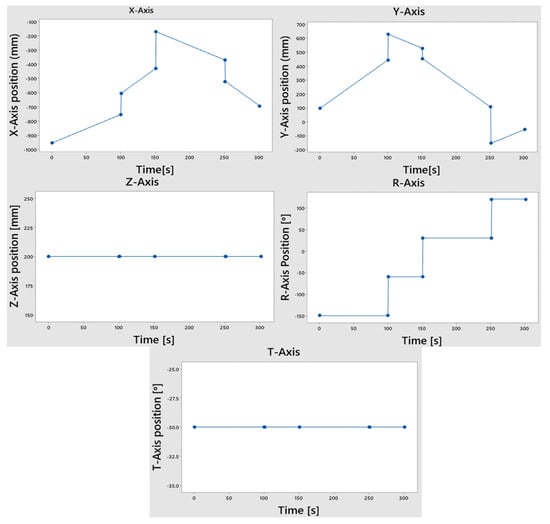
Figure 11.
The 5-DoF robot’s axis trajectory displacement with time in a rectangular motion.
Similar profile motion experiments were conducted with a 6-DoF-articulated robot for comparison. Figure 12 illustrates the rotational position of each axis of the 6-DoF industrial articulated robot over time during a rectangular motion. These experiments provide valuable insights into the performance and capabilities of both robotic systems in handling complex welding tasks with precision and efficiency.
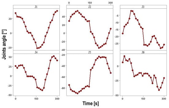
Figure 12.
The 6-DoF-articulated robot axis rotational position with time in rectangular motion.
5.2. Circular Path Trajectory Experiment
The experiment evaluated the robot’s ability to perform circular path welding. The robot executed a circular motion with a diameter of 360 mm. Interestingly, the X- and Y-axis actuators completed the circular movement independently, while the Z-axis remained stationary. This is because the Cartesian XY plane was kept parallel to the welding table surface throughout the process.
Figure 13 showcases the robot performing both circular and rectangular trajectory welding tasks. Notably, even though the welding torch length remained constant, the tilting ability of the robot allowed for the consistent maintenance of the welding angle throughout the entire circular rotation.
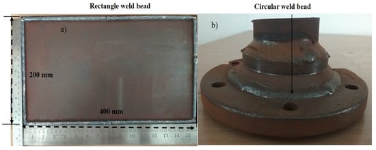
Figure 13.
The 5-DoF robot’s rectangle and circular trajectory path welding.
Figure 14a,b offers a schematic representation of the joint motion for both circular and rectangular paths. This visual aid helps us to understand how the robot’s actuators maneuver to achieve the desired welding trajectories. The experiments demonstrate the robot’s versatility and precision in handling complex welding tasks with varying profiles and orientations. During circular motion, the welding torch moves seamlessly within the same plane, while the X- and Y-axis actuators remain positioned outside the circular path. Interestingly, all five actuators are engaged during this movement, highlighting the coordinated effort required for precise execution. Figure 15 further illustrates the joint positions of the 5-DoF robot during the circular path trajectory.
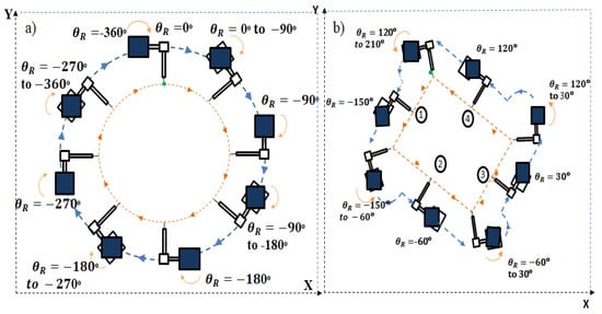
Figure 14.
(a) Schematic representation of circular and (b) rectangular path joint motion.
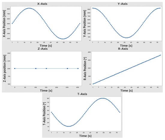
Figure 15.
The 5-DoF robot joint position for circular trajectory.
The circular motion experiment was also performed on a 6-DoF-articulated robot. A meticulous evaluation process tracked and graphed all joint motions for precise performance analysis. Figure 16 shows a graph depicting the position (in degrees) of each joint in the 6-DoF robot over time. Here, the trajectory displacements of the joints consider the output of the gearboxes, while the actual translation is determined by multiplying the gear ratios. Notably, each joint of the 6-DoF robot requires more translation to achieve the desired rectangular and circular paths compared to the 5-DoF robot. These experimental data offer valuable insights into the capabilities and limitations of both robotic systems for handling complex welding tasks with precision and efficiency.
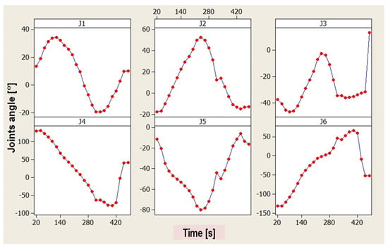
Figure 16.
The 6-DoF robot joint position for circular trajectory.
Table 4 presents the joint trajectory displacement data for both robots, showcasing the movement required for circular and rectangular paths. The experiments within the XY plane revealed an advantage of the 5-DoF robot. Here, a minimal number of axes were actively engaged, with each joint undergoing minimal translational movement. This approach resulted in an efficient trajectory for the robot. On the other side, all six joints of the 6-DoF-articulated robots exhibited the maximum rotational movement to achieve the desired trajectories. To accurately represent the servo motor angle position, the joint’s translational movement was multiplied by the gear ratio. This considered both the rotational and translational aspects of the joint’s movement, allowing for the precise calculation of the servo motor angle. These findings offer valuable insights for optimizing robot trajectories in various welding tasks, ensuring efficient and precise execution.

Table 4.
Joint Trajectory displacement of the 5-DoF robot and 6-DoF robot articulated for circular and rectangular path trajectory.
5.3. Power Utilization for Linear Path Trajectory Experiment
To investigate the power consumption during linear path welding, the robots executed a trajectory between two waypoints with a 660 mm distance with a 30° orientation, requiring coordinated joint movement. To assess power utilization, each servo drive system in the 5-DoF robot was calibrated to measure the power consumption, both individually and for the entire system. This calibration involved a measuring tool (power clamp meter) connected between the power supply and the servo drive.
The experiments were conducted at various velocities while maintaining other parameters constant. Both the 5-DoF robot and 6-DoF-articulated robot were used. Figure 17a,b depicts the experimental setups for power utilization in each robot type. Table 5 and Table 6 provide detailed data on the trajectory displacement and power utilization of each joint. Additionally, Figure 18a,b illustrates how power consumption in each joint varies with the velocity for both robots, respectively.
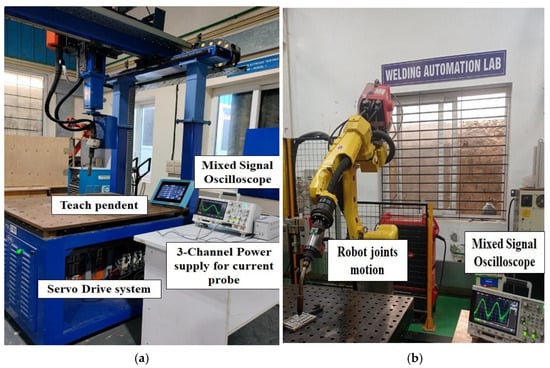
Figure 17.
Power utilization experimental setup of (a) the 5-DoF robot and (b) the 6-DoF-Articulated robot.

Table 5.
Trajectory displacement and power utilization of each joint of the 5-DoF robot.

Table 6.
Trajectory displacement and power utilization of each joint of the 6-DoF-Articulated robot.
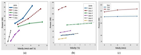
Figure 18.
(a) The 5-DoF Robot: each joint’s power concerning velocity; (b) the 6-DoF-Articulated Robot: each joint’s power concerning velocity; and (c) power utilization comparison between the 6-DoF and 5-DoF robot.
These experiments explored how the robot performance and power consumption vary at different welding speeds during linear path trajectories. The findings provide valuable insights for optimizing robot efficiency in welding applications.
Figure 18 compares the power consumption of the 5-DoF and 6-DoF robots during the linear path welding experiments. The results reveal that the 5-DoF robot consumes less energy than the 6-DoF robot. This difference in power consumption can be primarily attributed to the design characteristics of each robot. The 5-DoF robot uses prismatic joints for some movements, whereas the 6-DoF robot uses mostly revolute joints (rotary joints). Prismatic joints generally require less power to operate compared to revolute joints, contributing to the 5-DoF robot’s improved energy efficiency.
The 5-DoF robot’s design, particularly its 2R manipulator utilizing revolute joints and efficient prismatic joints, contributes significantly to the lower power consumption. This translates to benefits in applications where energy efficiency is crucial.
By minimizing power usage, the robot offers potential advantages in terms of:
- Reduced operating costs.
- A lower environmental impact.
- These factors make the 5-DoF robot a compelling choice for various industrial tasks.
5.4. Results and Validation
The newly developed 3P2R manipulator methodology offers increased flexibility with efficient manipulation, supporting enhanced benefits in industrial automation sectors. The forward and inverse kinematic modeling of the 5-DoF robot, incorporating prismatic manipulators, is easily understandable for a new application interface. The MATLAB simulation demonstrates end-effector trajectory flexibility, showcasing variations in the joint parameters. The following benefits were identified from the new methodology.
5.4.1. Avoiding Singularity Errors
A crucial advantage of the 5-DoF robot’s design is its ability to avoid singularity errors. Singularity errors occur when certain robot configurations prevent further movement.
MATLAB R2023a simulations were conducted to analyze the forward and inverse kinematics of the robot’s joint motions under various parameters. The results showed that the robot’s 2-DoF wrist manipulator generates trajectories within its cubical workspace without encountering singularity errors. In contrast, standard 6-DoF-articulated robots can experience these errors during complex tool orientations, limiting their movement.
Therefore, the 3P2R manipulator methodology offers significant advantages:
- Increased Flexibility: the robot can perform a wider range of motions without encountering limitations due to singularity errors.
- Reduced Complexity: by avoiding singularity errors, the 5-DoF robot eliminates the need for more complex 6-DoF-articulated robots in certain applications.
The 3P2R methodology’s flexible trajectory control makes it suitable for various tasks, such as Welding applications, Additive manufacturing processes, PCB soldering, and Electronic component assembly.
5.4.2. Reduces the Number of Joints
Articulated robots often require a balance between speed, precision, and the ability to maneuver the tool in various orientations. The 5-DoF robot achieves this by combining the strengths of two mechanisms:
- The 3-DoF Cartesian Manipulator: this component provides precise and efficient positional control for the robot’s base.
- The 2-DoF Serial Manipulator: this section offers the flexibility to orient the tool (like the welding torch) in different directions.
By integrating these mechanisms, the 5-DoF robot overcomes the limitations of a single design and achieves the necessary flexibility for various industrial tasks.
5.4.3. Efficient Joint Trajectory and Accuracy
The experimental results demonstrate the efficient movement capabilities of the 5-DoF robot’s joints. The X, Y, and Z axes can each achieve their full range of motion independently. In contrast, 6-DoF-articulated robots might require using all their axes simultaneously, reaching their maximum rotation limits. This five-axis design optimizes joint movements for various applications by allowing individual axes to reach their full potential without needing complex coordination.
Another advantage of the 5-DoF robot lies in its use of linear actuators. These actuators have a lower inertia and produce fewer vibrations compared to the rotary motors found in articulated robots. This allows the 5-DoF robot to utilize lower-torque motors, reducing energy consumption. Combined, the efficient joint motion and use of low-torque motors contribute to the robot’s overall energy efficiency and its ability to operate effectively within a cubical workspace.
5.4.4. Lower Power Consumption
The experiments confirm that the 5-DoF robot consumes less power than the 6-DoF-articulated robot. This difference stems from the design of their actuators:
- The 6-DoF-Articulated Robot: The serial manipulator uses rotary motors that connect to the links indirectly. To move the entire robot, these motors require high torque, leading to a higher power consumption.
- The 5-DoF Robot: The 3-DoF linear actuators directly control the position of the links. They have a lower friction coefficient and require less torque to move the robot, resulting in a lower power consumption.
This design choice contributes significantly to the 5-DoF robot’s energy efficiency.
5.4.5. User-Friendly Welding Interface and Enhanced Efficiency
The robot is equipped with a user-friendly HMI that simplifies the control of both the robot motion and welding parameters. This integrated system combines the welding power source, industrial teach pendant, and robot controller for a streamlined operation.
The single interface screen provides easy access to the robot trajectory and welding parameter controls, making it user-friendly for operators of all experience levels.
This design philosophy has a significant impact on the robot’s overall performance:
- Reduced Power Consumption: the integrated system potentially reduces the power consumption by eliminating the need for separate controllers.
- Improved Efficiency: the simplified interface allows for faster and more efficient operation.
- Versatility: The robot’s capabilities extend beyond welding to include tasks like additive manufacturing, material handling, drilling, assembly, and packing. The compact design makes it well-suited for various industrial applications.
6. Conclusions
This research proposes a novel 5-DoF robot design for industrial automation, featuring a combination of three prismatic and two revolute (2R) joints, and analyzes its workspace which addresses limitations in the trajectory motion present in commonly used 6-DoF-articulated robots. The kinematic model integrates both parallel and serial manipulator principles, combining a Cartesian mechanism with rotational mechanisms. The developed robot demonstrates a superior performance and user-friendliness in welding. The experimental work validates the design’s optimized joint trajectories, efficient power usage, singularity avoidance, easy access in application areas, and cost effectiveness due to fewer actuators compared to 6-DoF-articulated robots.
The parallel manipulator guides the tool position and the serial manipulator provides the orientation of the tool trajectory, generated through forward and inverse kinematics modeling using the Denavit–Hartenberg methodology. This unique design eliminates the need for a higher DoF robot and mitigates singularity errors. The developed HMI display offers various geometric shapes such as round, rectangle, and triangle, additive applications, and provides control settings for welding parameters in single operations. The proposed manipulator’s control system is user-friendly, enabling a quick setup and operation even for unskilled workers. By integrating the welding parameters with an efficient motion trajectory, the system achieves smooth control, resulting in high-quality welds.
Further, the developed 5-DoF kinematic model scheme has been validated through MATLAB simulation experiments by varying the joint parameters. The trajectory simulation is employed for analyzing internal and external disturbances, as well as joint parameter uncertainties. The comparison of the joint trajectory experimental results indicates that the manipulator optimizes the joint-motion trajectory, utilizes power optimally, and achieves an effective position and orientation in welding applications. This methodology demonstrates the flexible motion achieved within a minimum DoF, reducing the manipulator manufacturing cost and increasing the usage effectiveness. The system’s flexible configuration supports effective actions in various applications such as inspection, packing, and assembly. Future efforts will focus on standardizing the 5-DoF robot design to facilitate wider adoption. This will significantly reduce manufacturing costs, making the system a compelling choice for small-scale industries seeking affordable automation solutions.
Author Contributions
Methodology, S.K. and S.M.; Validation, S.K. and S.M.; Formal analysis, S.K.; Investigation, S.K. and S.M.; Writing—original draft, S.K.; Writing—review & editing, B.V.; Supervision, S.M. and B.V. All authors have read and agreed to the published version of the manuscript.
Funding
This research received no external funding.
Data Availability Statement
Data are contained within the article.
Conflicts of Interest
The authors declare no conflict of interest.
References
- Li, S.; Zhang, X. Research on planning and optimization of trajectory for underwater vision welding robot. Array 2022, 16, 100253. [Google Scholar] [CrossRef]
- Gnanavelbabu, A.; Arunagiri, P.; Dhanasekar, D. Implementation of Robotic Welding for the Improvement of Production Systems. Int. J. Eng. Trends Technol. 2017, 49, 304–309. [Google Scholar]
- Alatartsev, S.; Stellmacher, S.; Ortmeier, F. Robotic Task Sequencing Problem: A Survey. J. Intell. Robot. Syst. 2015, 80, 279–298. [Google Scholar] [CrossRef]
- Wang, T.; Pan, B.; Fu, Y.; Wang, S.; Ai, Y. Design of a new haptic device and experiments in minimally invasive surgical robot. Comput. Assist. Surg. 2017, 22, 240–250. [Google Scholar] [CrossRef] [PubMed]
- Roy, S.S.; Pratihar, D.K. Kinematics, Dynamics and Power Consumption Analyses for Turning Motion of a Six-Legged Robot. J. Intell. Robot. Syst. 2013, 74, 663–688. [Google Scholar] [CrossRef]
- Mustafa; Aalim, M. Modeling, Simulation and Control of 2-R Robot. Glob. J. Res. Eng. Robot. Nano-Tech 2014, 14, 49–54. [Google Scholar]
- Asokan, T.; Seet, G.; Iastrebov, V.; Senanayake, R. Kinematic Design and Analysis of a 7 Degree-of-Freedom Dual-Stage Inspection Manipulator for Dexterous Subsea Applications. J. Intell. Robot. Syst. 2003, 38, 277–295. [Google Scholar] [CrossRef]
- Patel, S.; Sobh, T.M. Manipulator Performance Measures—A Comprehensive Literature Survey. J. Intell. Robot. Syst. 2004, 77, 547–570. [Google Scholar] [CrossRef]
- Francalanza, E.; Fenech, A.; Cutajar, P. Generative design in the development of a robotic manipulator. Procedia CIRP 2018, 67, 244–249. [Google Scholar] [CrossRef]
- Franceschi, P.; Mutti, S.; Pedrocchi, N. Optimal design of robotic work-cell through hierarchical manipulability maximization. Comput. Integr. Manuf. 2022, 78, 102401. [Google Scholar] [CrossRef]
- Wiktor, P. Coupled Manipulators. Mech. Mach. Theory 2021, 161, 103903. [Google Scholar] [CrossRef]
- Kim, D.W.; Lee, W.B.; Song, J.B. Design of a linear gravity compensator for a prismatic joint. In Proceedings of the IEEE International Conference on Intelligent Robots and Systems, Las Vegas, NV, USA, 24 October–24 January 2020; pp. 6440–6445. [Google Scholar]
- Eliot, E.; Deepak, B.B.L.V.; Parhi, D.R.; Srinivas, J. Design and Kinematic Analysis of an Articulated Robotic Manipulator. Int. J. Mech. Ind. Eng. 2014, 4, 3. [Google Scholar] [CrossRef]
- Singh, G.; Banga, V.K. Kinematics and trajectory planning analysis based on hybrid optimization algorithms for an industrial robotic manipulators. Soft Comput. 2022, 26, 11339–11372. [Google Scholar] [CrossRef]
- Shah, J.; Rattan, S.S.; Nakra, B.C. End-Effector Position Analysis Using Forward Kinematics For 5 Dof Pravak Robot Arm. IAES Int. J. Robot. Autom. 2013, 2, 112–116. [Google Scholar] [CrossRef]
- Hongtang, C.; Ma, H.; Jiang, H.; Lv, S.; Li, Y.; Liu, H. Kinematic Modeling of 3P2R Welding Robot Based on D-H Parameters. J. Phys. Conf. Ser. 2022, 2218, 012085. [Google Scholar] [CrossRef]
- Wang, Y.; Zhao, C.; Liu, Z.; Peilun, Z.; Li, P.; Liu, H. Inverse Kinematics of a 7-DOF Spraying Robot with 4R 3-DOF Non-spherical Wrist. J. Intell. Robot. Syst. 2021, 101, 1–17. [Google Scholar] [CrossRef]
- Pott, P.P.; Wagner, A.; Badreddin, E.; Weiser, H.; Schwarz, M.J. Inverse Dynamic Model and a Control Application of a Novel 6-DOF Hybrid Kinematics Manipulator. J. Intell. Robot. Syst. 2010, 63, 3–23. [Google Scholar] [CrossRef]
- Clothier, K.E.; Shang, Y. A Geometric Approach for Robotic Arm Kinematics with Hardware Design, Electrical Design, and Implementation. J. Robot. 2010, 2010, 984823. [Google Scholar] [CrossRef]
- Vasanthakumar, M.; Vinod, B.; Jayant Kumar, M.; Santhakumar, M. Design and Robust Motion Control of a Planar 1P-2PRP Hybrid Manipulator for Lower Limb Rehabilitation Applications. J. Intell. Robot. Syst. 2018, 96, 17–30. [Google Scholar] [CrossRef]
- Pachaiyappan, S.; Balraj, M.M.; Sridhar, T. Design and analysis of an articulated robot arm for various industrial applications. J. Mech. Civil Eng. 2014, 1, 42–53. [Google Scholar]
- Marcel, L.; Leonardo, M.; Arturo, G. Modelling, Design and Validation of a Parallel Kinematic Robot for Additive Manufacture Applications. Ann. Robot. Autom. 2021, 5, 019–029. [Google Scholar] [CrossRef]
- Pambudi, W.S.; Alfianto, E.; Rachman, A.; Hapsari, D.P. Simulation design of trajectory planning robot manipulator. Bull. Electr. Eng. Inform. 2019, 8, 196–205. [Google Scholar] [CrossRef]
- Vasava, V.M.; Prajapati, A.B. Design and analysis of wireless welding arm. Int. J. Mech. Prod. Eng. Res. Dev. 2016, 6, 9–24. [Google Scholar]
- Yi, J.; Qingqing, H.; Zhaoen, D.; Chao, Z.; JianFeng, Y.; Chunjian, H. Structural design and kinematic analysis of a welding robot for liquefied natural gas membrane tank automatic welding. Int. J. Adv. Manuf. Technol. 2022, 122, 461–474. [Google Scholar] [CrossRef]
- Agbaraji, E.C.; Inyiama, H.C.; Obiora-dimson, I. Joint Torque and Motion Computational Analysis for Robotic Manipulator Arm Design. J. Eng. Appl. Sci. 2020, 12, 1–9. [Google Scholar]
- Zhong, J.; Wang, T.; Cheng, L. Collision-free path planning for welding manipulator via hybrid algorithm of deep reinforcement learning and inverse kinematics. Complex Intell. Syst. 2021, 8, 1899–1912. [Google Scholar] [CrossRef]
- Dumas, C.; Caro, S.; Garnier, S.; Furet, B. Joint stiffness identification of six-revolute industrial serial robots. Robot. Comput. Integr. Manuf. 2011, 27, 881–888. [Google Scholar] [CrossRef]
- Gaidhane, P.K.; Nigam, M.J.; Kumar, A.; Pradhan, P.M. Design of interval type-2 fuzzy precompensated PID controller applied to two-DOF robotic manipulator with variable payload. Isa Trans. 2019, 89, 169–185. [Google Scholar] [CrossRef]
- Sanz, A.; Etxebarria, V. Experimental Control of a Two-Dof Flexible Robot Manipulator by Optimal and Sliding Methods. J. Intell. Robot. Syst. 2006, 46, 95–110. [Google Scholar] [CrossRef]
- Kah, P.; Shrestha, M.; Hiltunen, E.; Martikainen, J. Robotic arc welding sensors and programming in industrial applications. Int. J. Mech. Mater. Eng. 2015, 10, 1–6. [Google Scholar] [CrossRef]
- Xiao, R.; Xu, Y.; Hou, Z.; Xu, F.; Zhang, H.; Chen, S. A novel visual guidance framework for robotic welding based on binocular cooperation. Robot. Comput.-Integr. Manuf. 2022, 78, 102393. [Google Scholar] [CrossRef]
- Wang, G.; Arora, H. Research on Continuous Trajectory Planning of Industrial Welding Robot Based on CAD Technology. Comput. Aided Des. Appl. 2021, 19, 74–87. [Google Scholar] [CrossRef]
- Pachidis, T.; Lygouras, J.N. Vision-Based Path Generation Method for a Robot-Based Arc Welding System. J. Intell. Robot. Syst. 2007, 48, 307–331. [Google Scholar] [CrossRef]
Disclaimer/Publisher’s Note: The statements, opinions and data contained in all publications are solely those of the individual author(s) and contributor(s) and not of MDPI and/or the editor(s). MDPI and/or the editor(s) disclaim responsibility for any injury to people or property resulting from any ideas, methods, instructions or products referred to in the content. |
© 2024 by the authors. Licensee MDPI, Basel, Switzerland. This article is an open access article distributed under the terms and conditions of the Creative Commons Attribution (CC BY) license (https://creativecommons.org/licenses/by/4.0/).