Abstract
Aimed at the problem of human–machine interaction between patients and robots in the process of using rehabilitation robots for rehabilitation training, this paper proposes a human–machine interactive control method based on an independently developed upper limb rehabilitation robot. In this method, the camera is used as a sensor, the human skeleton model is used to analyse the moving image, and the key points of the human body are extracted. Then, the three-dimensional coordinates of the key points of the human arm are extracted by depth estimation and spatial geometry, and then the real-time motion data are obtained, and the control instructions of the robot are generated from it to realise the real-time interactive control of the robot. This method can not only improve the adaptability of the system to individual patient differences, but also improve the robustness of the system, which is less affected by environmental changes. The experimental results show that this method can realise real-time control of the rehabilitation robot, and that the robot assists the patient to complete the action with high accuracy. The results show that this control method is effective and can be applied to the fields of robot control and robot-assisted rehabilitation training.
1. Introduction
In recent years, with the change of lifestyle and the influence of aging, the number of stroke patients has increased significantly, and about 60% of patients have upper limb motor dysfunction after the disease. In the existing rehabilitation training programmes, the robot-assisted training method has been sought after due to its high efficiency and good rehabilitation effect, and the research on rehabilitation robots and their control systems has gradually become an area of focus.
Many research teams have made good progress in the field of upper limb rehabilitation robots. For example, some exoskeletal robots are controlled by surface electromyographic signals [1], and some robots are driven by pneumatic muscle actuators [2] to assist users in performing upper limb movements. ANYexo2.0 [3], with its unique motion structure and bionic control shoulder coupling, allows users to train most everyday upper limb movements and interact with real objects. However, such devices typically have a complex structural design, take up a large amount of space and are not easy to carry. To solve this problem, people began to study desktop upper limb rehabilitation robots. For example, the cable-driven three-degree of freedom rehabilitation robot [4], and a desktop upper limb rehabilitation robot [5] designed by a team from Changzhou University based on the McNamm wheel, which abandoned the complex structure of the exoskeleton and avoided the problem of large size common to end-pull robots. A similar rehabilitation system is ArmAssist [6], a rehabilitation platform that can not only automatically assess the athletic ability of the user, but also help the therapist to provide remote supervision.
In terms of an interactive control system, Meng et al. proposed an active interactive controller based on motion recognition and adaptive impedance control [7], and applied it to a 6-DOF parallel lower limb rehabilitation robot. Guo et al. proposed an interactive control method of a lower limb exoskeleton robot using an adaptive admittance model [8]. Guang et al. proposed an interactive upper limb rehabilitation robot [9], which can display the motion trajectory through a parallel mechanism and a non-equidistant screen on the platform, and provide users with the most intuitive visual feedback. There are also many similar robotic rehabilitation systems that have been designed with visual feedback [10,11], which greatly improves user engagement in the process of use and enables them to achieve better rehabilitation effects. At the same time, the robot control system, when combined with the image processing method, has also achieved good results in the experiment. For example, Hyung S.N. et al. proposed a robot treatment device that uses a visual assistant algorithm to extract user intention [12]. Similarly, the precision control system of an upper limb rehabilitation robot proposed by Bang et al. is based on camera image processing [13].
At present, many treatment programmes combined with rehabilitation robots have been applied, but such methods have not been able to achieve large-scale promotion and popularisation. Specific reasons include, but are not limited to, the high cost of equipment, the complexity of operating the systems, and the need for medical staff to provide guidance. Also, the fact that many systems need to be set up and adapted for different users before use, which increases time costs.
Therefore, in this study, we proposed an interactive control method of an upper limb rehabilitation robot based on image processing. This method uses a monocular camera to capture motion images, uses a human skeleton model to analyse the human node in the image, and then extracts the coordinates of the upper limb node by combining the space geometry method to calculate the motion data of the upper limb and generate control instructions accordingly, realising the real-time control of the robot. This method can improve the adaptability of the system to individual differences and environmental changes, and reduce the difficulty of system operation, thus solving the problem of the current interactive control system being too difficult to popularize on a large scale.
2. System Structure
2.1. Overall Structure of Interactive Control Systems
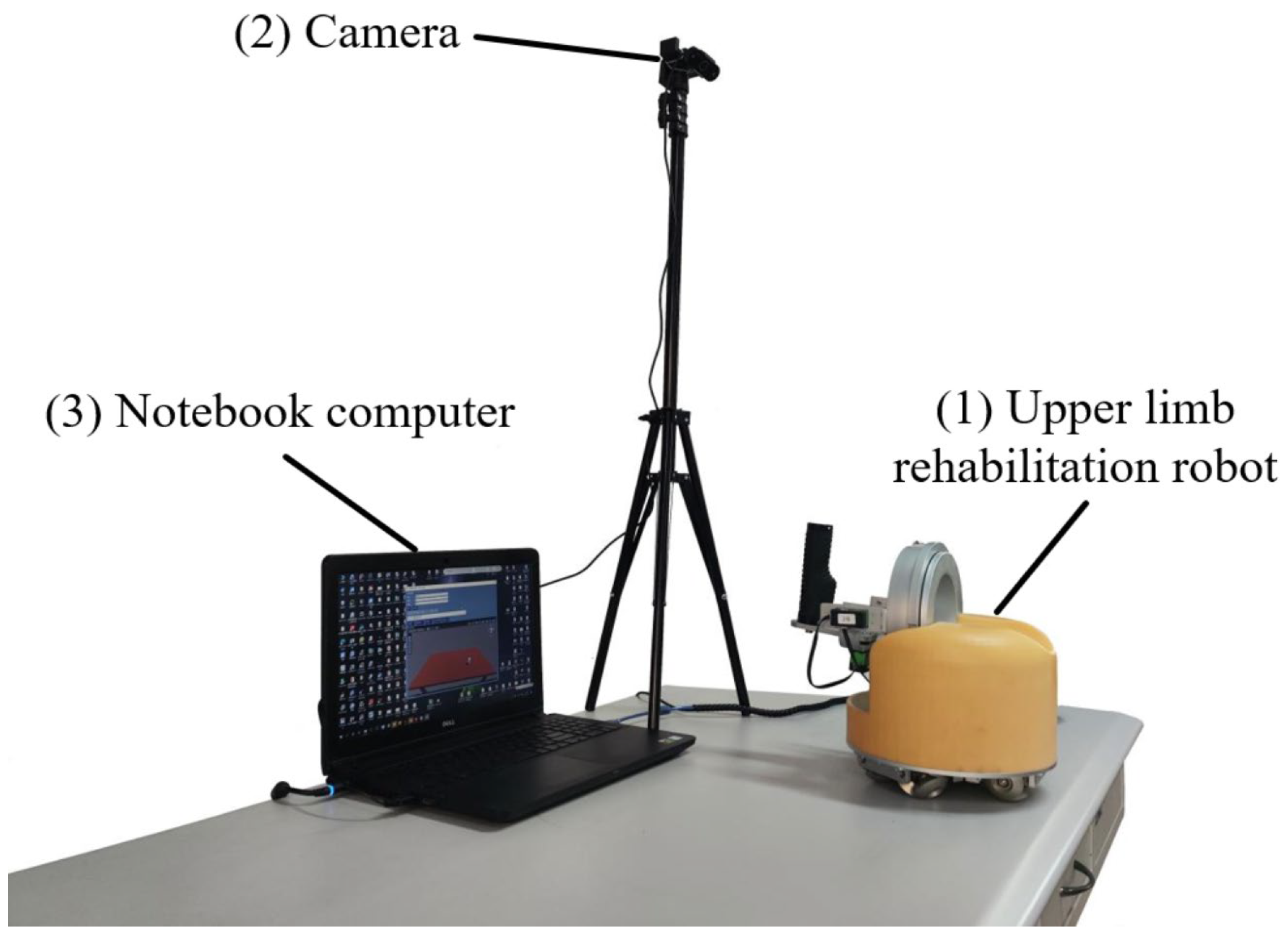
The overall structure of the system is shown in Figure 1. The system is composed of the following parts.
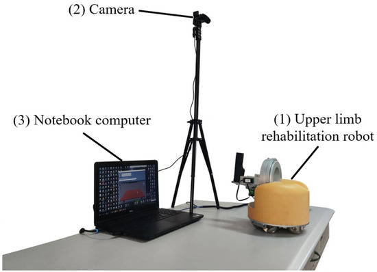
Figure 1.
Overall structure of the rehabilitation training system.
(1) Table-top upper limb rehabilitation robot. This paper selects an upper limb rehabilitation robot designed by Shenyang Aerospace University in China, which supports both active and passive movement, and aims to meet patients’ needs for rehabilitation training at home. To achieve this goal, the overall design of the robot focuses on a compact structure and easy operation, and the main structure of the robot is divided into an omnidirectional mobile platform at the bottom and a mechanical movement unit at the top. Such a design ensures that patients have sufficient room to move during rehabilitation exercises, and the robot has the characteristics of small size and offers convenient use.
(2) USB camera. The camera selected in this paper is produced by Shenzhen Tafeike Technology Co., Ltd., Shenzhen, China. It is used to capture motion images to extract human motion data as input signals for the control system. Compared with cognitive human–computer interaction for biological signal acquisition, although the performance of physical human–computer interaction in the interaction process is not as intuitive and natural as the former, it is more stable and will not cause large errors due to individual differences and environmental changes. Considering that some limbs of stroke patients still have the ability to move after the disease, the movement data of the healthy limbs is chosen as the input signal of the control system. The use of image analysis can not only greatly improve the adaptability of the control system to individual differences, but also reduce the effect of environmental changes and improve the robustness of the system.
(3) Laptop. The laptop used in this paper is made by Dell in Xiamen, China. It is used to analyse the motion image, extract the motion information and generate control commands. The generated commands are transmitted to the Arduino board of the lower computer via serial communication to realize the control of the robot. At the same time, the host computer also provides an interactive interface for rehabilitation training, and the user can receive the task instruction of the movement through the interactive interface, and then perform the corresponding action.
2.2. Mechanical Structure of Rehabilitation Robot
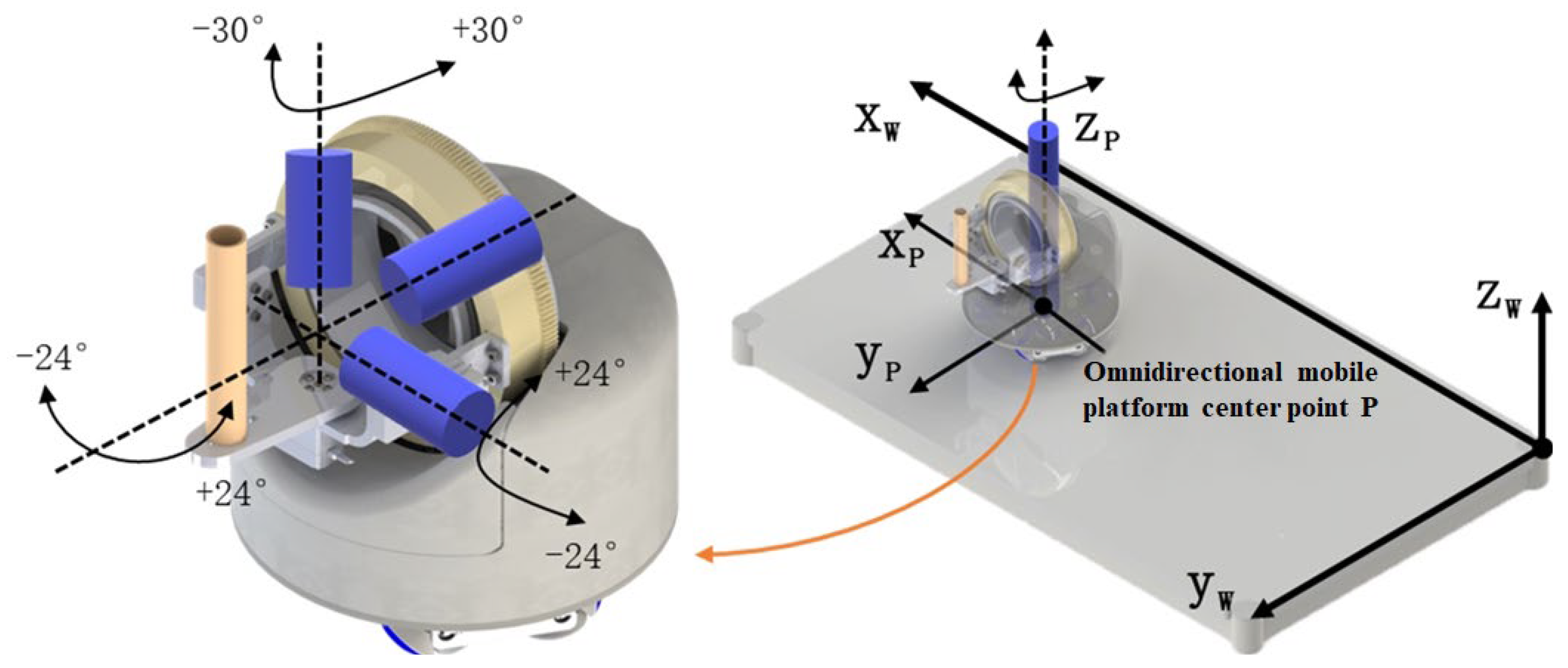
The robot part of this system selects a self-developed desktop upper limb rehabilitation robot [14], and its overall structure and freedom diagram are shown in Figure 2. The robot is mainly divided into two parts: wrist rehabilitation mechanism and omnidirectional mobile platform. Among them, the omnidirectional mobile platform adopts the design of MY wheel set [15,16], which can carry the same or more weight in a smaller size while ensuring mobility.
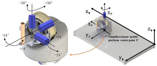
Figure 2.
Overall structure and freedom of upper limb rehabilitation robot.
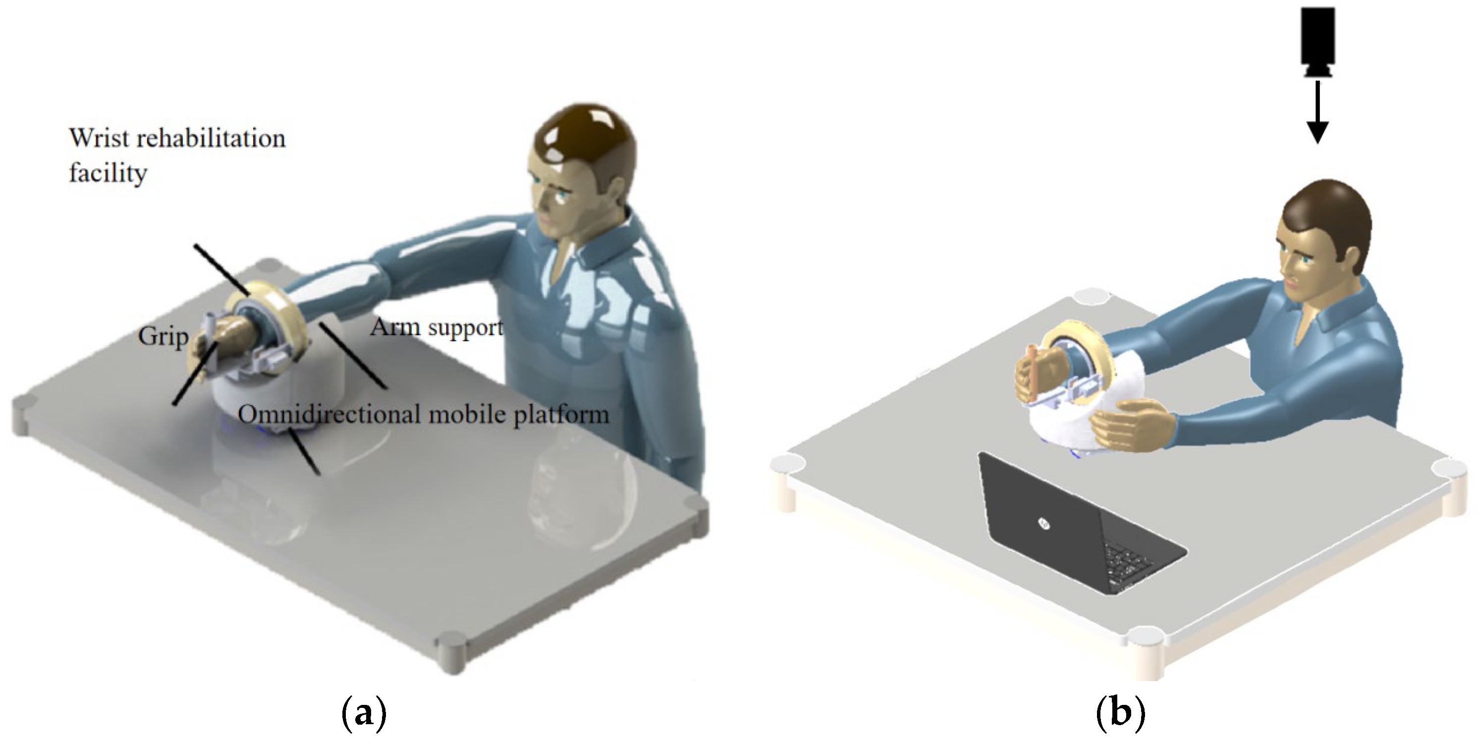
The schematic diagram of the upper limb rehabilitation robot in actual use is shown in Figure 3. The patient should place his forearm on the arm rest, hold the foremost grip of his hand and perform the wrist rehabilitation movements of palmar/dorsiflexion, radial/ulnar flexion and forearm rotation using the three-degrees-of-freedom wrist rehabilitation actuator. Elbow flexion/extension and horizontal shoulder rotation are performed by the robot moving on the table in all directions to provide upper extremity rehabilitation training.
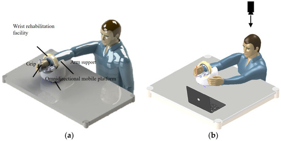
Figure 3.
Schematic diagram of upper limb rehabilitation robot: (a) passive movement and (b) active movement.
The patient can perform both passive and active movements with the help of the robot. The interactive mode designed in this paper is shown in Figure 3b. By analysing the motion image of the patient’s healthy arm captured by the monocular camera, the motion data are obtained, and then new instructions are generated to realise the real-time control of the robot.
3. Control Method
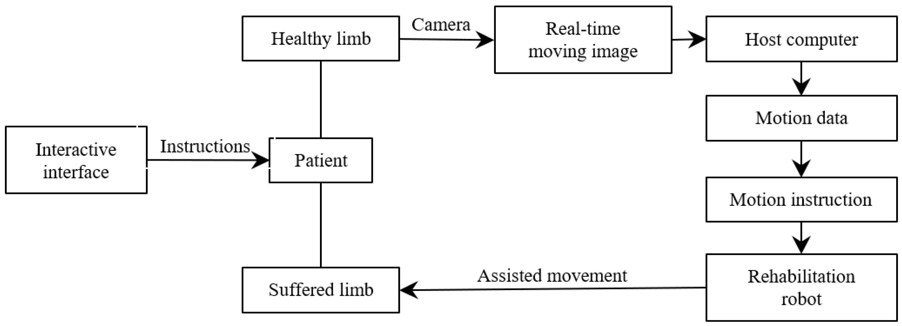
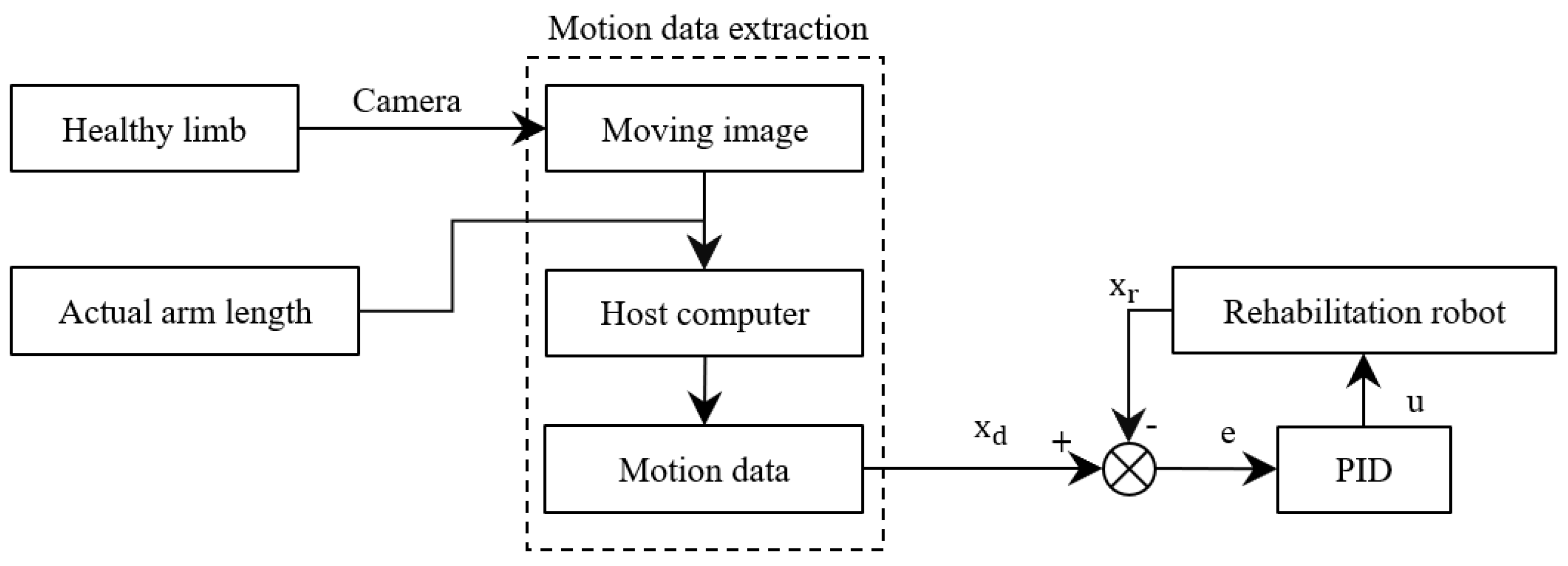
The structure block diagram of the interactive control method proposed in this paper is shown in Figure 4. Firstly, the interactive interface gives the task instructions, and the patient moves the healthy measuring limbs to perform corresponding actions according to the requirements after receiving the instructions. The camera captures the patient’s movement process in real time, obtains the movement data of the patient’s healthy arm by analysing the motion picture, updates the control command of the rehabilitation robot in real time, and assists the patient’s sick arm to complete the movement, thus realizing the patient’s real-time interactive control of the robot.
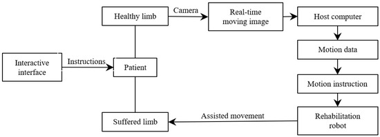
Figure 4.
Block diagram of control system of rehabilitation robot.
3.1. Motion Data Analysis Based on a 2D Image
Mediapipe is an open-source multimedia processing framework developed by Google, in which the skeleton frame can be used to detect and track human bone key points in real time. Based on deep learning and computer vision technology, it uses a loss function to optimize model performance and improve model stability [17,18]. It not only shows good accuracy in detecting key points, but also shows good robustness in processing tasks in different scenes and under different lighting and occlusion conditions. It is very suitable for identifying human motion information in real life.
Usually, the methods for analysing video streams or images to obtain human body information are to adopt deep learning methods or use depth cameras, but the former has a large amount of computation, and the latter has high requirements on the environment and equipment, which is not suitable for large-scale promotion. Therefore, this paper uses a monocular camera to capture the image, analyses the image using a human skeleton model, and calculates the two-dimensional coordinates of the upper limb joint points in preparation for the subsequent solution of the three-dimensional coordinates.
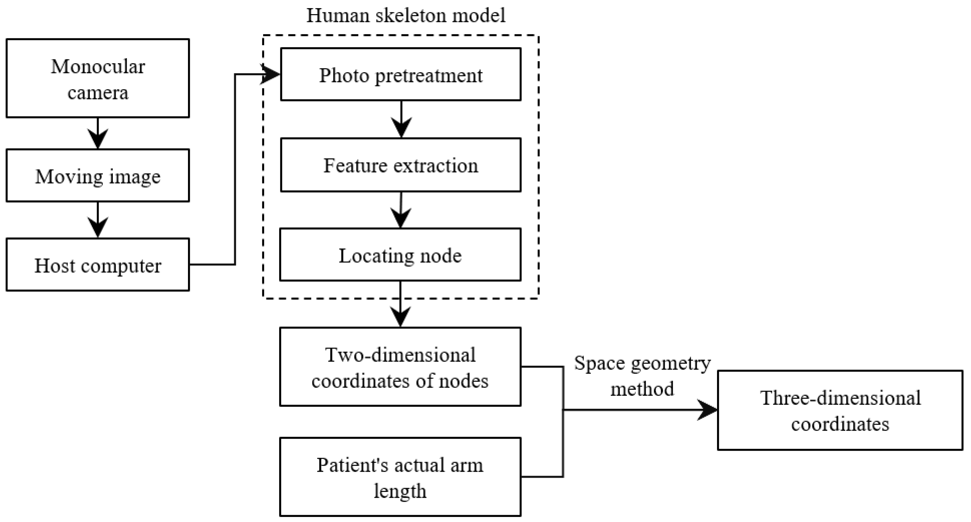
The specific process of solving the three-dimensional coordinates is shown in Figure 5.
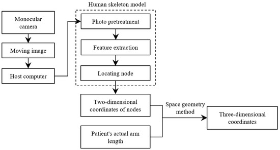
Figure 5.
The process of obtaining the three-dimensional coordinates of upper limb joint points.
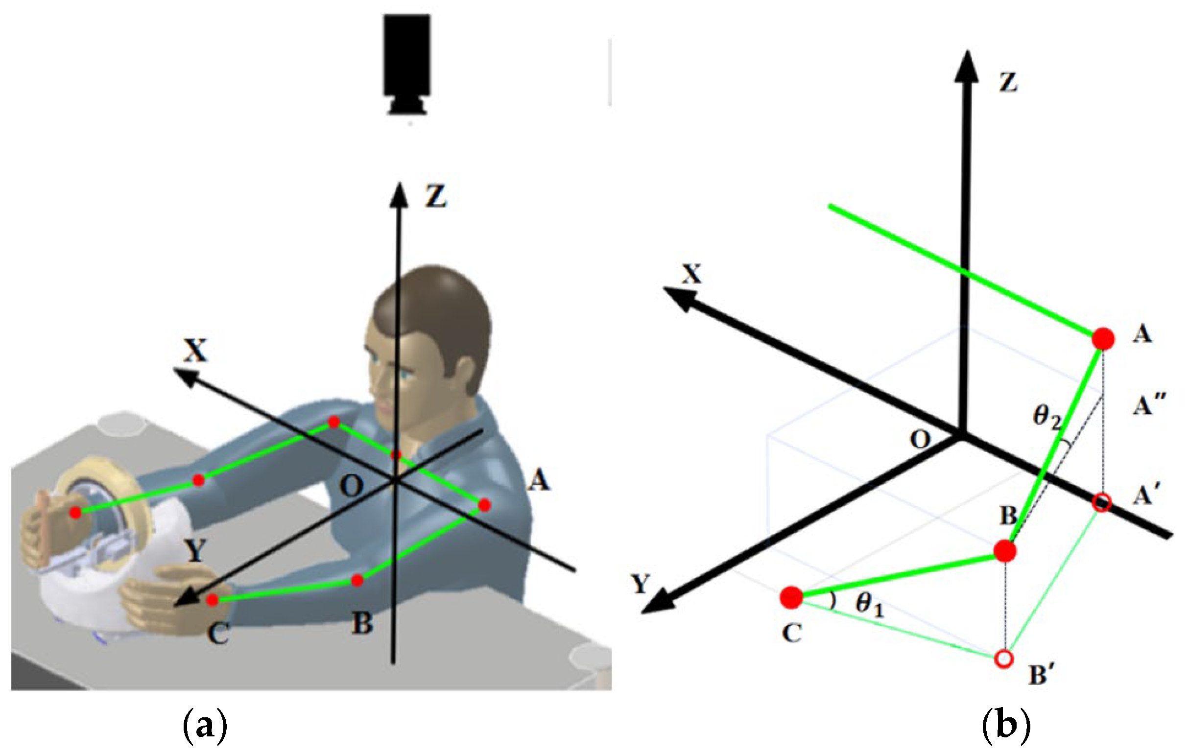
When solving three-dimensional coordinates, the first step is to establish a world coordinate system cantered on the patient. Due to the construction of the rehabilitation robot, it can only move on a horizontal plane, and since the patient’s hand is always close to the grip when using it, the coordinate system can be established with the surface of the patient’s wrist as the horizontal plane and the centre of the patient’s body as the centre of the circle, as shown in Figure 6. The monocular camera is positioned directly above the patient to obtain the projection data of the upper limb on the horizontal plane. Before use, it is necessary to measure the real data of the patient’s arm, i.e., the real lengths of AB and BC.
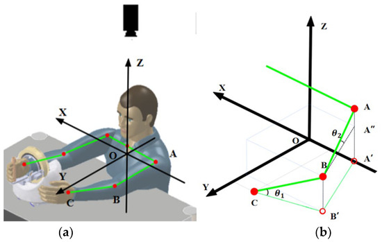
Figure 6.
(a) New coordinate system; (b) three-dimensional coordinate solution diagram.
Then, the key points of the human body are identified. After the monocular camera streams the video to the host computer, it is analysed using a human skeletal frame. First, the OpenCV library is called to read an image for key point identification, here taking a frame of the video image. The image is then pre-processed to meet the input requirements, including resizing, colour space conversion and normalisation. Next, the model uses a convolutional neural network for feature extraction and a detection algorithm to locate the key points of the human body, which are finally given in the form of coordinates and marked in the image.
According to the imaging principle, the length shown in the image taken by the monocular camera is the projected length of the human body, i.e., the position and two-dimensional coordinates of points A′, B′ and C are obtained through the skeleton. As shown in Figure 6b, the height of the human elbow point B can be obtained from Formulas (1) and (2) as follows:
Similarly, the height of the shoulder joint point A can be obtained, and the three-dimensional coordinates of the key points of the upper limb can be calculated by combining the two-dimensional coordinates of the three key points obtained; then, the movement data of the upper limbs (joint velocity and angular velocity) can be calculated. Taking the wrist joint as an example, the specific formula is as follows:
- Δt—time interval, the interval between two image analyses;
- x1, y1, z1—the coordinates of the wrist in the first image;
- x2, y2, z2—the coordinates of the wrist in the second image.
The movement data of the shoulder joint and elbow joints were calculated in the same way.
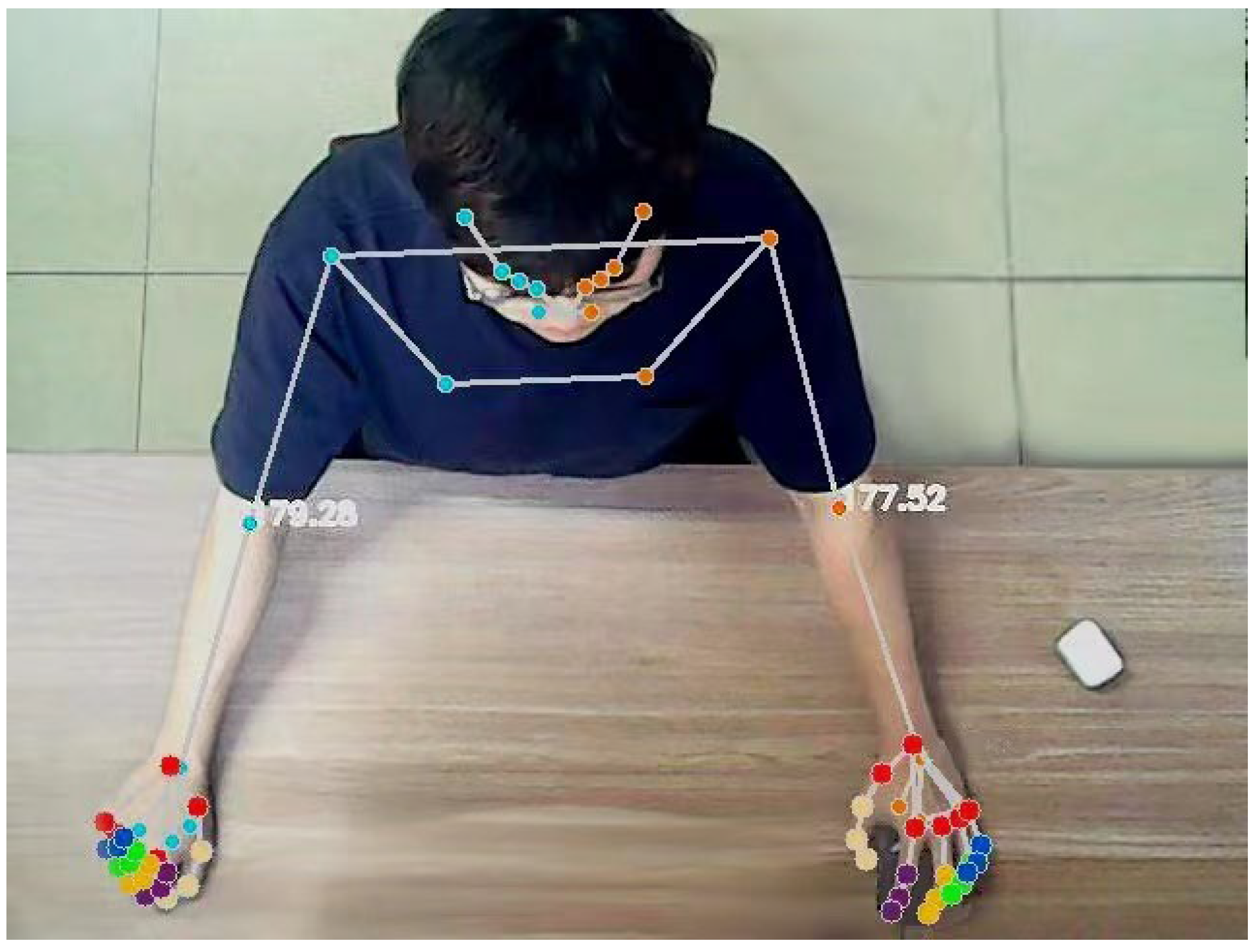
At the same time, to further evaluate the patient’s movement, it is also necessary to calculate the user’s joint angle. Assuming that the coordinate points of the shoulder joint, elbow joint and wrist joint are A, B and C, respectively, the angle of the elbow joint can be obtained from the following formula. The effect of the actual operation is shown in Figure 7.
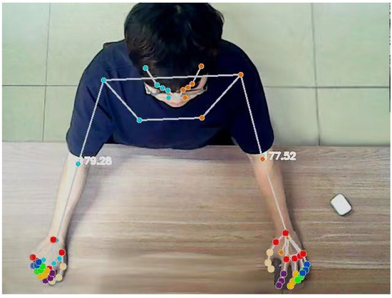
Figure 7.
Real-time output diagram of upper limb joint and elbow joint angle.
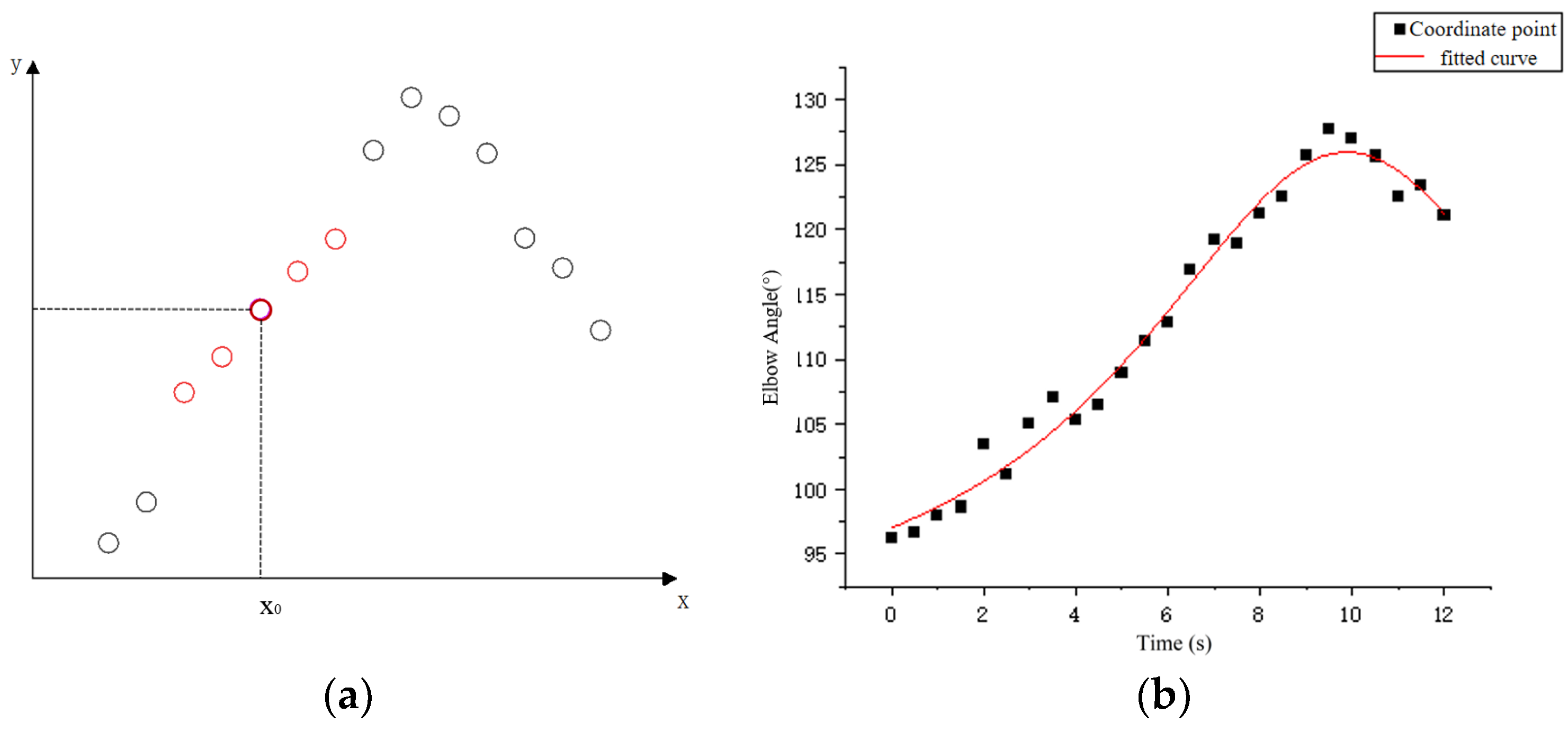
Considering the uncontrolled limb shaking that may occur in stroke patients, the coordinate sequence was smoothed before extracting the motion data to reduce irregular fluctuations in the data. According to the type and amount of data obtained from the host computer, the local weighted regression algorithm is selected to smooth the data. As shown in Figure 8a, the method needs to assign a certain weight to the points near each data point to be calculated, and then perform normal regression based on the minimum mean square error on this subset.
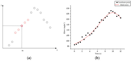
Figure 8.
(a) Schematic diagram of locally weighted regression and (b) data series fitting.
First, the bandwidth factor is set, the window length is calculated, and the number of samples involved in each fit is determined; k is the nearest positive integer. Secondly, the data points in the sequence to be processed are selected and the weights are calculated according to the distance between them and their neighbours.
The cubic weight function is selected for this calculation as follows:
- —the normalised distance between the sample point and the fit point in the X direction;
- —the distance between the furthest sample point and the fit point in the X direction;
- —cubic weight function.
The reason for choosing a cubic weight function is that the system is mainly designed for patients with hemiplegia caused by stroke. During rehabilitation robot training, the patient’s arms may shake or move uncontrollably, so there will be many abnormal data points in the collected data set. Compared to the quadratic weighting function, the cubic weighting function gives less weight to sample points far from the target region and is less sensitive to outliers. Therefore, it can better handle data abnormal points and reduce their impact on the regression results.
The weights of the data points are calculated as follows:
After calculating the weights, the best regression coefficient β and fitting point (x, y) are calculated using the least squares method to minimise the loss function of locally weighted regression. The loss function expression is as follows:
- xi, yi—coordinates of the fitting point;
- β—the best regression coefficient;
- v(xi)—the weight of the fit point.
By repeating the above steps, all data points in the original sequence are fitted and the LOESS regression curve is obtained. The data points in the curve can be considered as the result of smoothing. Figure 8b shows the effect of using this method to process the time series of elbow joint angle changes; the fitted effect is shown in the figure. After processing the coordinate sequence of the key points, the motion data of the patient’s healthy arm can be calculated through the coordinate points.
3.2. Human–Computer Interactive Control
After realizing the 3D pose construction and motion data extraction based on 2D images, the interactive control program of the rehabilitation robot is designed. Considering that the patient’s upper limb movement is relatively large in the process of rehabilitation training, in order to enable the robot to stably follow the upper limb movement of the human body, improve the accuracy and flexibility of control, and make the robot’s action closer to the human body, the PID algorithm is selected to introduce feedback control. By comparing the real-time motion data of the user’s wrist with the current motion state of the rehabilitation robot, a feedback loop is established. Then, the output of the controller is calculated by the ratio, integral and differential gain and current error to control the motion of the rehabilitation robot.
The formula of PID control is as follows:
- KP—proportional gain;
- Ki—integral gain;
- Kd—differential gain;
- e(t)—error signal.
In the process of programming the PID controller, the manual tuning method is chosen to find the appropriate gain coefficient. After the manual tuning of the PID controller has been completed in Python, by observing the changes in the feedback signal, a set of gain coefficients with the best effect is finally selected. Based on this feedback control method, considering that the trajectory of the relevant movements of the upper limb will change due to the length difference of the user’s upper limb, the final control scheme also introduces the correction of the movement trajectory, and finally realizes the real-time control of the rehabilitation robot. In this control system, xd represents the expected position of the end of the experimenter’s arm on the side supported by the robot during movement. Assuming that the shoulder joint of the healthy arm of the experimenter is point A, the elbow joint is point B, and the wrist joint is point C, the coordinates of the three points A, B and C are obtained by the three-dimensional coordinate extraction method. With reference to the established coordinate system, it can be calculated by the mirror image method regarding the expected coordinates of xd (−xc, yc, zc), and the rotation angle of the robot at this point can be calculated by the vector BC. The calculation formula is as follows:
The specific control policies are shown in the following Figure 9.
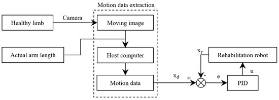
Figure 9.
Rehabilitation robot feedback control process.
4. Rehabilitation Training Experiment
Mirror therapy is a rehabilitation treatment that uses visual feedback and mirroring to create illusions to improve the motor function of the limb. The principle is that by pre-senting the healthy limb and the affected limb symmetrically in the mirror, the patient ob-serves the movement of the healthy limb in the mirror, thereby stimulating the brain’s motor control of the affected limb. This illusionary stimulation can promote the remodelling and recovery of the nervous system, improving the range of motion, coordination and strength in the affected limb [19,20].
Based on this theory, we hope to help patients achieve true mirror movements through the above interactive control method. This means that after the system detects the movement of the patient’s healthy arm, it can control the rehabilitation robot to assist the patient’s sick arm in performing the corresponding movement. For patients, rehabilitation robots can help them move damaged limbs, exercise muscles and promote the recovery of athletic ability; furthermore, robot-assisted mirror therapy can provide two-way feedback to the patient’s brain and the affected limb, enhance the neuroplasticity process, and accelerate the recovery of neurological function in patients after stroke [21]. And the reason we chose the mirror experiment was to verify the performance of the interactive control system by comparing the similarity between the robot’s auxiliary action and the original action.
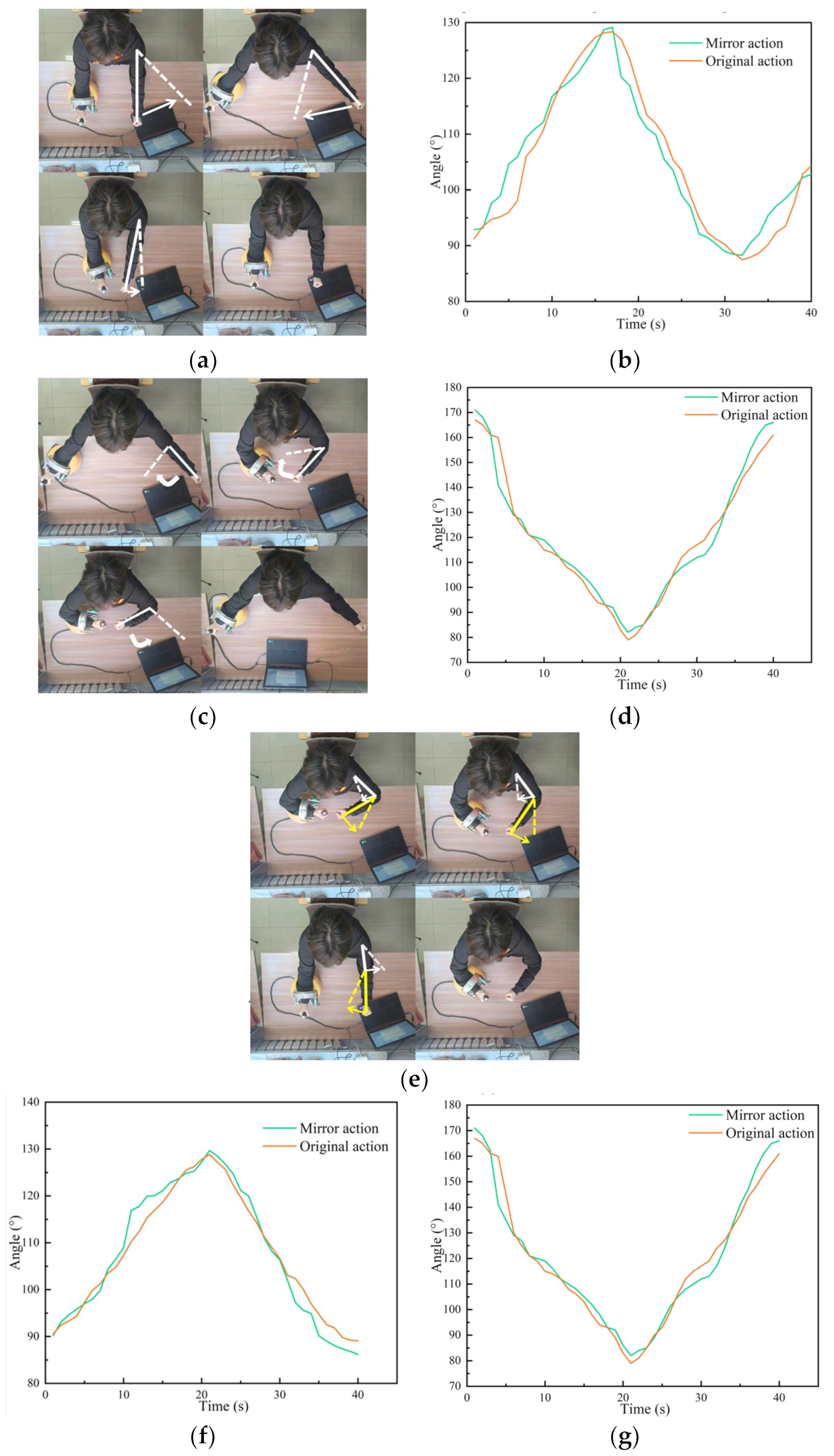
The specific procedure of the experiment was as follows. The experimenter moved his ‘healthy arm’ to perform an action according to the prompts of the interactive interface, the control system recognised the action, and controlled the rehabilitation robot to assist the experimenter’s other arm to complete the mirror action. In this experiment, three groups of movements were set up, namely shoulder joint horizontal swing, elbow joint horizontal swing and joint collaborative movement, and each movement was tested 10 times. During the experiment, angle sensors attached to both sides of the patient’s arm were used to measure the angle changes of the patient’s corresponding joints during the experiment. Finally, the two groups of time series obtained were analysed and the similarity between them was calculated to verify the performance of the control system. The experimental process and results are shown in Figure 10.
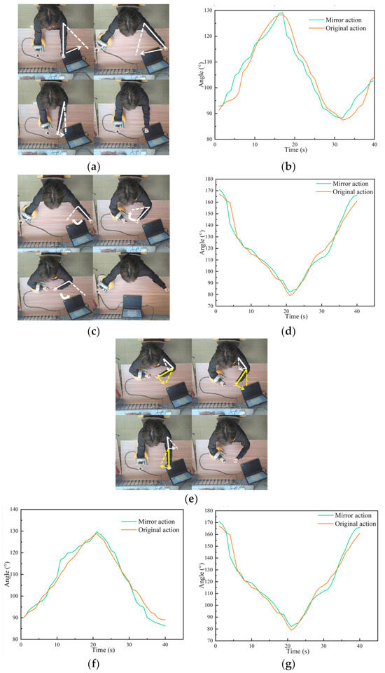
Figure 10.
Experimental process and experimental results: (a) shoulder movements; (b) image of the change in the shoulder joint angle; (c) elbow movement; (d) image of the change in the elbow joint angle; (e) push-pull operation; (f) shoulder angle; and (g) elbow angle.
To evaluate the experimental results, the Dynamic Time Adjustment (DTW) algorithm was selected to evaluate the similarity between the image motion and the original motion assisted by the robot, so as to verify the accuracy of the motion under the control method.
The DTW algorithm was designed to calculate the similarity of time series, using the idea of dynamic programming to calculate the shortest distance between different time series to achieve the highest similarity. After long-term experimental research on rehabilitation, it was verified that the DTW algorithm had achieved excellent results in the rehabilitation medical field.
Here are the steps to implement the DTW algorithm. First, assume that there are two time series X and Y.
Then, define an n × m matrix D, where D[i,j] is the distance between the i-th element of X and the j-th element of Y. Define the same matrix C again, using C[i,j] as the minimum distance from the first element of X to the i-th element, and from the first element of Y to the i-th element. The first step in the calculation is to initialise the boundary, i.e., to calculate the first row and the first column of C:
For i = 2 to n, and j = 2 to m, calculate
Finally, the resulting C[i,j] is the DTW distance between time series X and Y, which can be used to compare the similarity of the two actions.
5. Discussion
In order to verify the effectiveness of the rehabilitation robot, we conducted experiments. Ten experiments were carried out for each of the three movements, and the time series data of the corresponding joint angles of the two arms were collected. The DTW algorithm was then used to analyse the similarity between the mirrored movement and the original movement. The average similarity of the shoulder and elbow joints was calculated for horizontal push-pull. The specific conclusion data are shown in the following Table 1.

Table 1.
Similarity of bilateral arm movements.
From the information in the table, it can be seen that when training shoulder and elbow movements, the mirror movements assisted by the rehabilitation robot are very similar to the original movements, indicating that the control system has good control accuracy. And compared with traditional mirror therapy, our experimental method, although it has a certain delay, can help patients to practise practically and regain muscle movement.
To improve the real-time performance of the system, the image processing and coordinate extraction programs of the system run at a frequency of twice per second, and the generated instructions are transmitted via serial communication and then executed. The whole control system will respond to the experimenter’s actions within 0.8 s. Combined with the above two points, it can be assumed that the experimenter completed the mirror movement. This shows that the interactive control method proposed in this paper is effective, that patients can complete the real-time control of the rehabilitation robot through this method, and that the movement of the controlled robot has good real-time accuracy.
6. Conclusions
Due to the shortcomings of current rehabilitation training devices in human–machine interaction, this paper proposes a new human–machine interaction control method based on the existing omnidirectional mobile upper limb rehabilitation robot. Considering the lack of the robustness of cognitive human–machine interaction and the need to improve the adaptability of the interaction for different patients as much as possible, we choose to use the motion information of the user’s own healthy arm as the input control signal. By analysing the motion images captured by the camera, the human skeleton model and 3D pose reconstruction method are used to obtain the user’s pose information and motion information. This method can greatly improve the adaptability of the interaction mode to individual user differences and environmental differences. At the same time, the upper function generates new control instructions in real time and generates corrections according to changes in the user’s motion data to modify the robot’s motion instructions. The user can control the robot in real time by the feedback control method and ensure the accuracy of the motion at the same time. The experimental results show that the mirror action assisted by the rehabilitation robot has high real-time performance and high similarity to the original action. Therefore, the interactive control method proposed in this paper has a good effect and can be applied to the interactive control of the robot or the rehabilitation training of the rehabilitation robot.
There are some limitations of the proposed method. Firstly, the motion data extraction method proposed in this paper makes it difficult to extract the motion data of the hand part. The finger is occluded or overlapped in the image during the actual movement process, which makes it difficult to accurately locate the finger node. Because the distance between the wrist joint and the finger joint is too short, the change in length in the image is not obvious, and the calculation is prone to large errors, so the current method is only suitable for extracting the motion data of the torso. Secondly, when measuring the length data of the patients’ upper limbs before the experiment, the measurement results are prone to error due to the manual measurement method. Finally, the control method can only be applied to the upper limb rehabilitation robot mentioned in the paper at present, and it needs to be modified and adjusted appropriately if it is to be applied to other devices.
Potential research directions. The main advantage of this method is that it is highly adaptable, stable and easy to use. In the future, it can be combined with other types of rehabilitation robots, such as lower limb rehabilitation robots, to design a rehabilitation robot training programme that is easier to promote and use. At the same time, if the recognition precision and accuracy of the system can be improved, it can be combined with the hand rehabilitation robot to provide rehabilitation training programmes for the end of the limb. Finally, the control system is not only applicable to the human body, but can also be applied to the posture recognition and control of industrial equipment such as arm robots in the future.
Author Contributions
Conceptualization, C.Y.; methodology, C.Y. and Z.W.; software, Z.W.; writing—original draft preparation, Z.W.; writing—review and editing, S.Y. and C.J.; supervision, C.Y. and S.Y.; project administration, C.J. All authors have read and agreed to the published version of the manuscript.
Funding
This research was funded by the Research on Motion Stability of Omnidirectional DexterousRobot of Shenyang Aerospace University (Grant no. 20180520033) and the Shandong Provincial Key Research and Development Program (Major Scientific and Technological Innovation Project) (Grant no. 2019JZZY010128).
Data Availability Statement
The original data contributions presented in the study are included in the article, further inquiries can be directed to the corresponding authors.
Conflicts of Interest
The authors declare no conflicts of interest.
References
- Liu, Y.; Li, X.; Zhu, A.; Zheng, Z.; Zhu, H. Design and evaluation of a surface electromyography-controlled lightweight upper arm exoskeleton rehabilitation robot. Int. J. Adv. Robot. Syst. 2021, 18, 17298814211003461. [Google Scholar] [CrossRef]
- Chen, C.; Lien, W.; Chen, C.; Wu, Y. Implementation of an upper-limb exoskeleton robot driven by pneumatic muscle actuators for rehabilitation. Actuators 2020, 9, 106. [Google Scholar] [CrossRef]
- Zimmermann, Y.; Sommerhalder, M.; Wolf, P.; Riener, R.; Hutter, M. ANYexo 2.0: A fully actuated upper-limb exoskeleton for manipulation and joint-oriented training in all stages of rehabilitation. In IEEE Transactions on Robotics; IEEE: New York, NY, USA, 2023. [Google Scholar]
- Jin, X.; Jun, D.; Jin, X.; Seon, J.; Pott, A.; Park, S.; Park, J.; Ko, S.Y. Upper limb rehabilitation using a planar cable-driven parallel robot with various rehabilitation strategies. In Cable-Driven Parallel Robots, Proceedings of the Second International Conference on Cable-Driven Parallel Robots, Duisburg, Germany, 24–27 August 2014; Springer International Publishing: Berlin/Heidelberg, Germany, 2015; pp. 307–321. [Google Scholar]
- Zhang, W. Desktop Upper Limbs Rehabilitation Robot Control System Research. Ph.D. Thesis, Changzhou University, Changzhou, China, 2023. [Google Scholar]
- Garzo, A.; Jung, J.H.; Arcas-Ruiz-Ruano, J.; Perry, J.C.; Keller, T. ArmAssist: A telerehabilitation solution for upper-limb rehabilitation at home. IEEE Robot. Autom. Mag. 2022, 30, 62–71. [Google Scholar] [CrossRef]
- Meng, W.; Zhu, Y.; Zhou, Z.; Chen, K.; Ai, Q. Active interaction control of a rehabilitation robot based on motion recognition and adaptive impedance control. In Proceedings of the 2014 IEEE International Conference on Fuzzy Systems (FUZZ-IEEE), Beijing, China, 6–11 July 2014; IEEE: New York, NY, USA, 2014; pp. 1436–1441. [Google Scholar]
- Guo, B.; Han, J.; Li, X.; Yan, L. Human–robot interactive control based on reinforcement learning for gait rehabilitation training robot. Int. J. Adv. Robot. Syst. 2019, 16, 1729881419839584. [Google Scholar]
- Guang, H.; Ji, L.; Shi, Y.; Misgeld, B. Dynamic modeling and interactive performance of PARM: A parallel upper-limb rehabilitation robot using impedance control for patients after stroke. J. Healthc. Eng. 2018, 2018, 8647591. [Google Scholar] [CrossRef] [PubMed]
- Ding, Y.; Tay, E.H. An Interactive Training System for Upper Limb Rehabilitation Using Visual and Auditory Feedback. In Proceedings of the 5th International Conference on Robotics and Artificial Intelligence, Singapore, 22–24 November 2019; pp. 54–58. [Google Scholar]
- Pan, L.; Zhao, L.; Song, A.; Yin, Z.; She, S. A novel robot-aided upper limb rehabilitation training system based on multimodal feedback. Front. Robot. AI 2019, 6, 102. [Google Scholar] [CrossRef] [PubMed]
- Nam, H.S.; Hong, N.; Cho, M.; Lee, C.; Seo, H.G.; Kim, S. Vision-Assisted Interactive Human-in-the-Loop Distal Upper Limb Rehabilitation Robot and its Clinical Usability Test. Appl. Sci. 2019, 9, 3106. [Google Scholar] [CrossRef]
- Bang, M.S.; Kim, S.; Nam, H.S.; Kim, Y.J.; Oh, B.M.; Beom, J.; Seo, H.G.; Leigh, J.H.; Koh, S.; Park, S.W. Upper Limb Rehabilitation Robot Module and Upper Limb Rehabilitation System for Precision Control by Image Processing. Korean Patent 1018316020000, 19 February 2018. [Google Scholar]
- Tao, G.; Chen, L.; Ye, C.; Peng, J. Design of a Desktop Upper Limb Rehabilitation Robot. In Proceedings of the 2023 IEEE International Conference on Mechatronics and Automation (ICMA), Harbin, China, 6–9 August 2023; IEEE: New York, NY, USA, 2023; pp. 911–916. [Google Scholar]
- Ye, C.; Tong, Z.; Yu, S.; Jiang, C. Kinematic analysis of an omnidirectional mobile assembly robot. Robot 2016, 38, 550–556. [Google Scholar]
- Ma, S.; Ren, C.; Ye, C. An omnidirectional mobile robot: Concept and analysis. In Proceedings of the 2012 IEEE International Conference on Robotics and Biomimetics (ROBIO), Guangzhou, China, 11–14 December 2012; IEEE: New York, NY, USA, 2012; pp. 920–925. [Google Scholar]
- LeCun, Y.; Bengio, Y.; Hinton, G. Deep learning. Nature 2015, 521, 436–444. [Google Scholar] [CrossRef] [PubMed]
- Alzubaidi, L.; Zhang, J.; Humaidi, A.J.; Al-Dujaili, A.; Duan, Y.; Al-Shamma, O.; Santamaría, J.; Fadhel, M.A.; Al-Amidie, M.; Farhan, L. Review of deep learning: Concepts, CNN architectures, challenges, applications, future directions. J. Big Data 2021, 8, 53. [Google Scholar] [CrossRef] [PubMed]
- Jaafar, N.; Che Daud, A.Z.; Ahmad Roslan, N.F.; Mansor, W. Mirror therapy rehabilitation in stroke: A scoping review of upper limb recovery and brain activities. Rehabil. Res. Pract. 2021, 2021, 9487319. [Google Scholar] [CrossRef] [PubMed]
- Miryutova, N.; Samoylova, I.; Minchenko, N.; Tsekhmeystruk, E. Therapeutic effects of mirror therapy in patients after stroke. Vopr. Kurortol. Fizioter. I Lech. Fiz. Kult. 2021, 98, 14–23. [Google Scholar] [CrossRef] [PubMed]
- Othman, A.D.; Zakaria, N.A.C.; Hashim, N.; Mohamaddan, S. Exoskeleton Robotics Intervention as an Adjunctive Treatment in Enhancing Post-Stroke Upper Limb Neurorecovery. In Proceedings of the 2021 21st International Conference on Control, Automation and Systems (ICCAS), Jeju, Republic of Korea, 12–15 October 2021; IEEE: New York, NY, USA, 2021; pp. 1391–1396. [Google Scholar]
Disclaimer/Publisher’s Note: The statements, opinions and data contained in all publications are solely those of the individual author(s) and contributor(s) and not of MDPI and/or the editor(s). MDPI and/or the editor(s) disclaim responsibility for any injury to people or property resulting from any ideas, methods, instructions or products referred to in the content. |
© 2024 by the authors. Licensee MDPI, Basel, Switzerland. This article is an open access article distributed under the terms and conditions of the Creative Commons Attribution (CC BY) license (https://creativecommons.org/licenses/by/4.0/).

