1. Introduction
Many designs need compactly stowed configurations that can be deployed in their use environments, such as positioning systems [
1,
2,
3], space systems [
4,
5,
6], medical surgery devices [
7,
8,
9], and transportation [
10,
11]. The design of these compactly stowed systems have benefited from foldable solutions [
12], rolling solutions [
13,
14], and utilizing deployable lattices (sometimes known as
-Shells) [
15,
16,
17]. These different solutions can be accomplished by both traditional rigid mechanisms and compliant mechanisms. Traditional spring mechanisms result in significant thickness when fully compressed, limiting the minimum size of a stowed system. Most spring shapes may exhibit plastic deformation or an unpredictable and out-of-plane form under complete compression. In some cases, the characteristics of the use environment of these mechanisms are extreme, creating harsh conditions for traditional rigid joints to function in (e.g., due to the need for lubrication which can be susceptible to these harsh conditions or thermal expansion of the joints causing increased friction or changes in the backlash in the joints). Compliant mechanisms can be used to create biased systems towards low-energy states using the strain energy stored during the deflection of the mechanism. This idea employs a deployed state of the mechanisms in the as-fabricated state. The Euler spiral is an example of this low energy extended state, which can be compressed to flat, with stored strain energy in this flat state.
This work combines the Euler-spiral flexure proposed by Ynchausti et al. [
18] with the compliant orthoplanar spring proposed by Parise et al. [
19] to create a compliant orthoplanar spring whose as-fabricated state occurs in a position orthogonal to the plane (the mechanism is biased to be extended). The orthoplanar Euler-spiral spring is fabricated by default in an out-of-plane, zero-energy configuration, permitting deflection to a fully planar state. This allows it to retain stored strain energy in the flat position. Unlike conventional orthoplanar springs, it generates a reactive force in this planar state.
In addition, this work quantifies the stroke and force-deflection behavior for different configurations of the Euler-spiral orthoplanar spring to determine which configuration provides the best characteristics for given design cases.
2. Background
This work combines key concepts from compliant orthoplanar springs and Euler-spiral flexures to create an Euler-spiral orthoplanar spring.
2.1. Compliant Mechanisms
Compliant mechanisms are mechanical systems that transfer force or motion through the deflection of material [
20]. Benefits of compliant mechanisms include reduction in part count, ability to store strain energy, removal of friction due to the lack of traditional rigid hinges, and increased precision motion. These advantages prove particularly valuable in scenarios where regular maintenance is impractical or in harsh environmental conditions, such as extreme temperatures. Additionally, because the motion is based on the deflection of material, compliant mechanisms can be made from a variety of materials.
2.2. Compliant Orthoplanar Spring
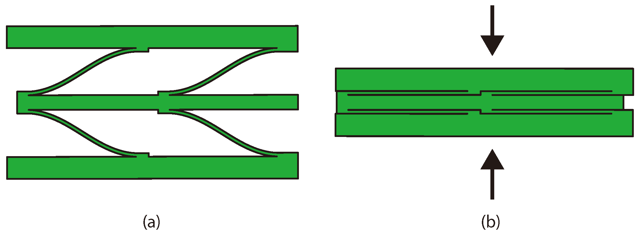
One such complaint mechanism is the compliant orthoplanar spring [
19], shown in
Figure 1a. These mechanisms usually consist of an outer rigid portion (or ring) and an inner rigid portion (or ring) connected by compliant legs that allow for out-of-plane deformation, while other orthoplanar springs existed before, the mechanism presented in Ref. [
19] allows for deployment orthogonal to the plane without rotation about the central axis during motion. The compliant orthoplanar spring has been used in designs for several applications, including mechanical vibration energy harvesting [
21], piezoelectric energy harvesting [
22,
23,
24,
25,
26], force sensing [
27,
28,
29], and uniformly and dynamically spacing a dielectric beam-scanning prism [
30]. Ref. [
19] also provides nomenclature to define the number of legs, compliant flexures, and orientation of the legs. Other research has sought to more fully define the mechanical behavior of the compliant orthoplanar spring [
31,
32,
33].
2.3. Euler-Spiral Flexures
An Euler spiral is a curve whose curvature is linearly proportional to its arc length [
34]. This characteristic allows the arc to assume a flat configuration under a load while storing strain energy. This makes it useful for areas that need smooth transitions, such as in parallel continuum robots [
35], reducing the shaking of sliding doors through optimization [
36], and in path tracking for autonomous vehicles [
37]. The Euler spiral has also been used in antenna design as a nanoantenna for a solar cell [
38] and can be found in nature in mammalian whisker shapes [
39,
40]. Yellowhorse and Howell [
41] proposed using an Euler-spiral-based compliant flexure as a lenticular stiffener for deployable systems. Ynchausti et al. [
18] used an anti-symmetric Euler spiral to create a flexure that lies flat underneath a load and can be connected between two rigid panels, known as deployable Euler-spiral connectors. See
Figure 2a for the uncompressed Euler-spiral flexure connected between two rigid panels and
Figure 2b to see it compressed (in the flat state).
3. Euler-Spiral Orthoplanar Spring
The Euler-spiral orthoplanar spring is a compliant mechanism that combines orthoplanar springs with Euler spirals. It is similar to the compliant orthoplanar spring proposed by Parise et al. [
19], but the legs are extended Euler-spiral flexures in the uncompressed state, instead of flat or in-plane with the spring. Compare
Figure 1a with
Figure 1b, which show the as-fabricated configurations of both springs. The Euler-spiral orthoplanar spring’s zero-energy state, the extended configuration (as-fabricated), enables it to store strain energy when subjected to force and deflected to a flat configuration. This stored energy allows the spring to exert a reaction force with near-zero thickness.
The Euler-spiral orthoplanar spring can have differing variations, similar to the orthoplanar spring presented in Ref. [
19]. The stroke and the force can be modified to determine the ideal variation of the spring. The stroke and force parameters are dependent on the quantity and dimensions of the Euler-spiral flexures. Furthermore, these flexures are governed by the overall diameter of the spring.
Additionally, the behavior of a stack of multiple Euler-spiral flexure-compliant orthoplanar springs under a load is of interest, especially when the springs are of different parameters.
3.1. Stroke of Euler-Spiral Orthoplanar Spring
The stroke of an Euler-spiral orthoplanar spring is determined by the dimensions of the legs. One leg is
Euler-spiral flexures in series. Therefore, the stroke (
) of a leg is determined using the equation for the maximum y-value from Ref. [
18] and multiplying by
or
where
is the maximum curvature of the flexure. The stroke of a leg with two flexures,
, is shown in
Figure 3.
3.2. Largest Dimensions of Euler-Spiral Flexure Based on Ring Diameter
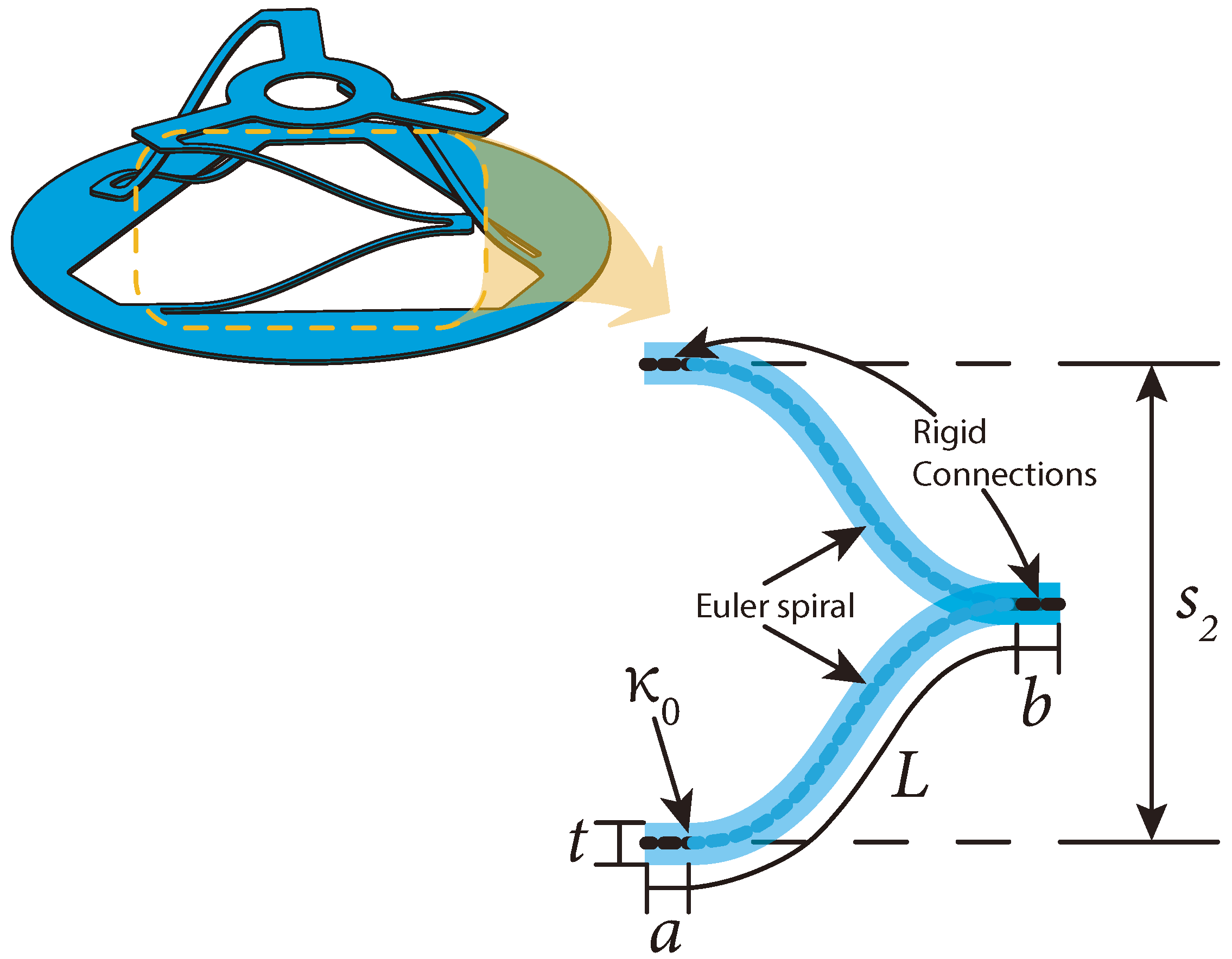
The largest dimensions of the Euler-spiral flexure can be determined for a given outer ring diameter (
), ring thickness (
), length of rigid connectors (
and
), the width of the flexures (
), space between the flexures (
), the number of legs (
), and are dependent upon the distance from the center of the ring (
) as
These dimensions are shown in
Figure 4a. The largest length will occur when
is at a minimum. This minimum distance from the center is determined by numerically solving the following equation, which was determined using the geometry shown in
Figure 4(bi,bii) for single flexures and double series flexures, respectively, as
where
and
is the number of legs around the orthoplanar spring. For example,
is equal to three in
Figure 4.
The maximum distance from the center that the legs can be placed is
At this location there is no space for the Euler-spiral flexures. This gives us an upper limit for our study.
3.3. Force-Deflection Curve of Euler-Spiral Orthoplanar Spring
Ref. [
18] establishes limits to avoid over-stress and under-stress which will be useful to this work. To avoid over-stressing the flexure during compression, the maximum curvature,
, should be in the range
where
is the yield stress of the material,
is the modulus of elasticity of the material,
is the thickness of the flexure, and
is the desired factor of safety. Additionally, the Euler-spiral flexure can be over-curved, meaning the top portion of the curve is above the bottom portion in the deployed position, which would invalidate the usefulness of the flexure lying flat under a vertical load. To avoid over-curvature, the product of the maximum curvature and length should remain below the limit
Further work has been conducted to optimize the deployable Euler-spiral connectors within a specific device [
42], as well as to create a pseudo-rigid-body model (PRBM) for Euler-spiral flexures [
43], that can be used to enable more efficient design and modeling.
To find the max deflection of an Euler-spiral orthoplanar spring begin with curve in a beam.
where
and
where
in Equation (
9) would be
/2 (half the total Euler-spiral arc length) and
is the width of beam. Note that Equations (
8)–(
10) are well-known equations for bending in a beam. Substituting Equations (
9) and (
10) into Equation (
8) gives
Solving for
gives
Because identical springs in parallel experience the same deflection, the force to deflect the total Euler spiral flexure is given by
where
is the number of legs. Using Equations (
1)–(
4) and (
13), trends were determined for
to
. These trends are shown in
Figure 4c,d. The study was begun at three parallel legs as three points are the minimum to define a plane, therefore, three legs would allow us to create an orthoplanar spring with the top platform guaranteed to be on a plane. Additional flexures only increase the force exerted by the spring, however, for the same given space, the stroke of the spring decreases as
increases.
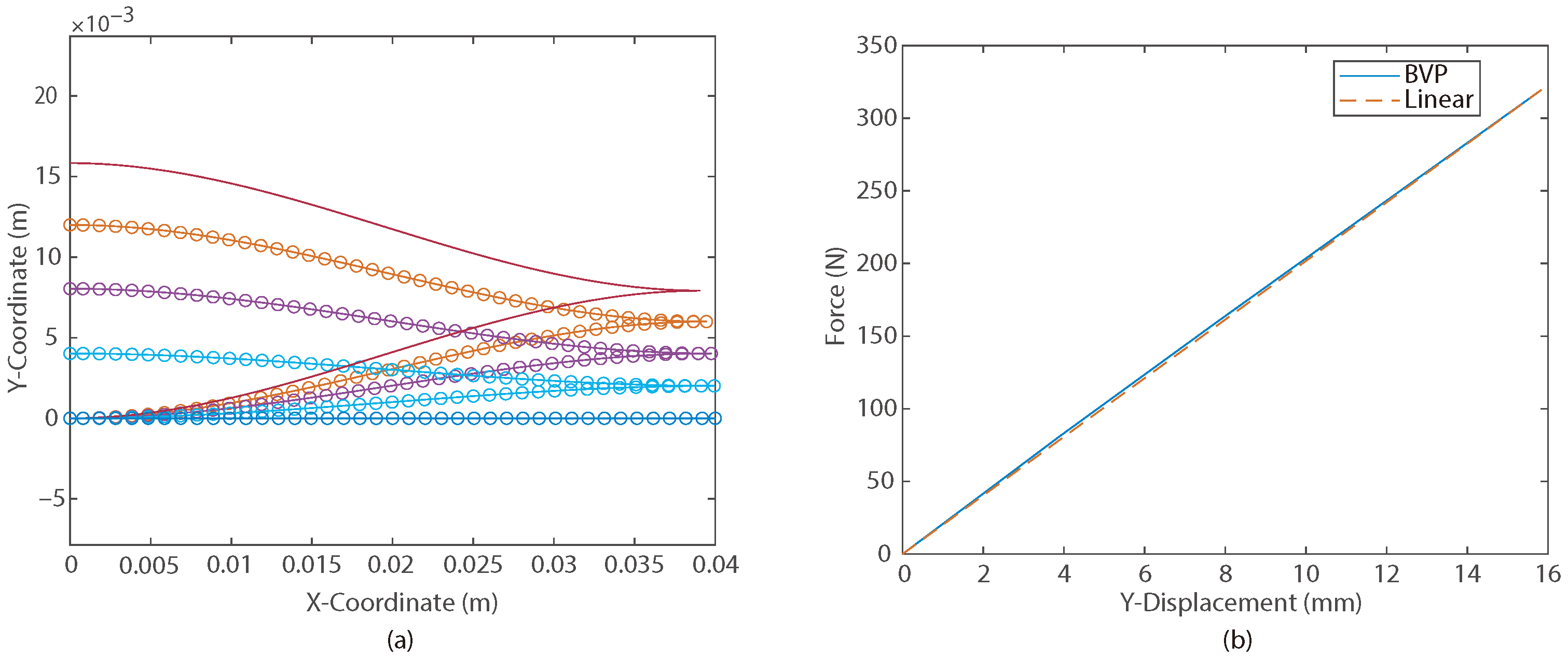
The force-deflection behavior of the deployable Euler-spiral connector (DESC) was shown in Ref. [
18] using a boundary value problem (BVP) and numerical integration methods to determine the endpoints of the beam based on given input force and moment conditions. Because each leg of the orthoplanar spring are two DESCs from [
18], the same formulation can be used, as these legs are four half DESCs in series. This means the force is the same in each half DESC, so the force will be the same; however, the overall deflection will be four times that of a half DESC. An example deflection diagram and corresponding force-deflection curve is shown in
Figure 5.
4. Fabrication Options
Different possibilities for fabricating orthoplanar springs using Euler-spiral flexures have been explored. The considerations taken into account were: tolerances, materials available, and feasibility of the geometry.
4.1. Additive Manufacturing
DMLS (Direct Metal Laser Sintering) is a metal additive manufacturing process that uses a high-powered laser to melt and fuse metal powder into desired shapes. The achievable tolerances in DMLS can vary depending on several factors, such as the material and the complexity of the part being printed. The typical linear dimensions tolerances for DMLS range from
0.05 mm to
0.2 mm. There are lots of metal materials that are supported by DMLS [
44].
FDM (Fused Deposition Modeling) 3D printing is an additional possibility to fabricate Euler-spiral orthoplanar springs.
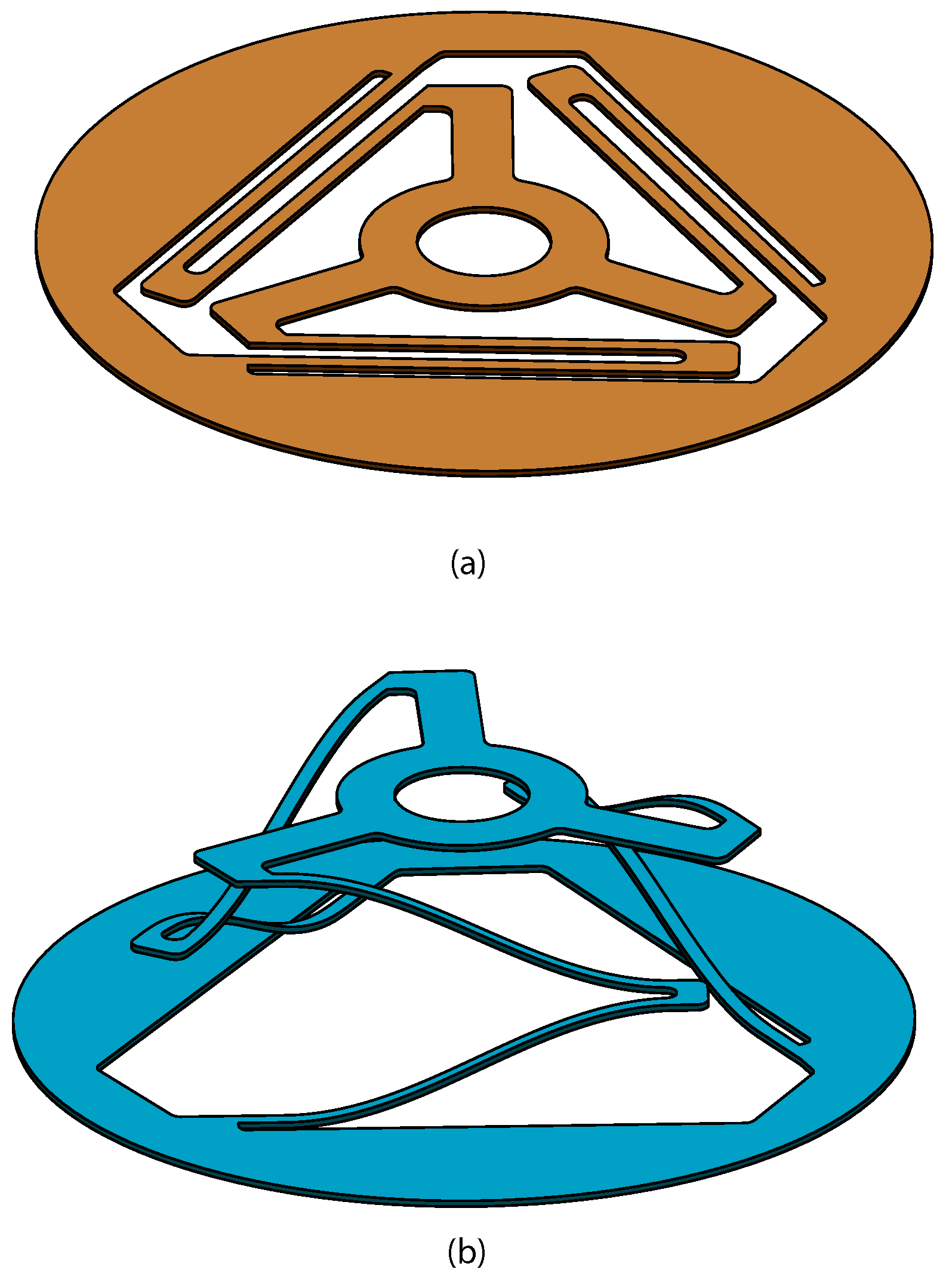
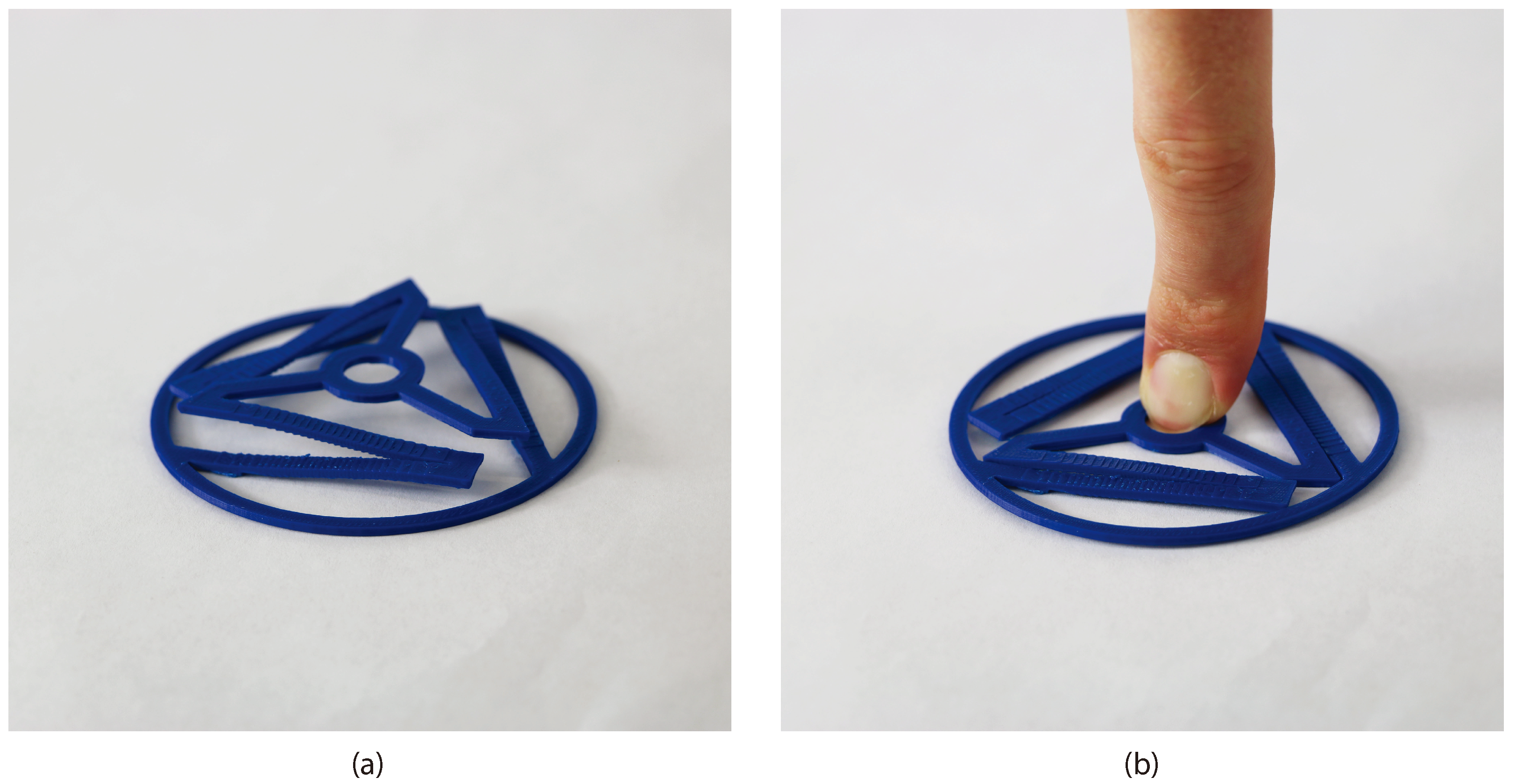
Figure 6a shows a PLA (Polylactic Acid) 3D printed Euler-spiral orthoplanar spring. Supports are required to print the spring due to its geometry. Supports with breakaway support material were used to achieve the necessary overhang features. Breakaway support material is used only for the layer that interfaces the part and the support because it is brittle and snaps off the part easily. This is shown in
Figure 7. See
Figure 6b for an image of a PLA 3D printed Euler-spiral othroplanar spring that is compressed flat by a force. FDM was chosen for validation in this study because it is inexpensive and allows for quick iterations.
4.2. Casting
Lost-wax casting, or investment casting, is a process used to create detailed metal components. It involves creating a wax pattern of the desired shape, coating it with a ceramic material to form a mold then heating it to melt and remove the wax. Molten metal is then poured into the mold, creating the final part. Lost-wax casting is known for producing intricate and complex geometries with high detail. It is used in various industries such as jewelry and aerospace. Lost-wax casting has been identified as a strong candidate to fabricate an orthoplanar spring using Euler-spiral flexures because it is capable of producing the required geometry.
4.3. Fiber Reinforced Composite Layup
Composite fiber lay-up is characterized by the arrangement of fiber-reinforced composite materials, often in the form of fabric sheets, within a mold or tooling structure. Through this method, the desired shape and mechanical properties of the part are achieved by layering and orienting the composite materials. Vacuum bagging or autoclave curing ensures the bonding of the layers and the formation of a structurally sound part. This approach is advantageous due to its capacity for geometric customization, offering an avenue for the fabrication of the Euler-spiral orthoplanar spring.
4.4. Fabricate Planar and Then Deform
A viable approach to fabricating an orthoplanar spring with Euler spirals involves the utilization of sheet metal stamping followed by precision deformation to achieve the Euler-spiral geometry. This method entails the creation of the spring’s basic outline through stamping processes on a sheet metal substrate. Subsequently, precise deformation techniques are employed to tailor the flat-stamped metal component to the specific geometry necessary for optimal functionality. To maintain the properties of the material such that the models in this paper can be used, heat setting/annealing would need to be utilized in this process.
4.5. Deep Draw Stamping
Deep drawing involves the transformation of a flat sheet of metal into a three-dimensional component through a well-established process. Because orthoplanar springs with Euler spirals have no overhangs deep drawing is an achievable option.
Springback would need to be taken into consideration for deep drawing and stamping flat when deforming so that the final is the desired position. Similar to
Section 4.4, heat setting/annealing would need to be utilized to keep the properties after deep drawing.
5. Sample Application
Considerable attention was devoted to the use of orthoplanar springs with Euler spirals as a means of deploying an antenna, attached to these springs, away from the fuselage of an aerial vehicle. The orthoplanar spring possesses the unique capability to remain in a state of stored strain energy while maintaining an almost negligible thickness. Maintaining an almost negligible thickness when stored is a characteristic introduced by the Euler-spiral flexures and is difficult to achieve with traditional springs. This renders it a highly efficient mechanism for optimizing available volume prior to mid-flight deployment. This attribute proves especially advantageous when accommodating an antenna that requires separation from the aircraft’s body to effectively capture desired signal frequencies. See
Figure 8 for a 3D model of this concept.
Furthermore, an additional advantage lies in the inherent stability of the deployed spring configuration. This characteristic makes use of deployment and retraction using a unidirectionally stiff mechanism, such as a cable, as opposed to requiring a stiff mechanism, like a rod, which enhances the overall operational efficiency of the system.
An additional advantageous aspect that was investigated involves the potential to stack multiple springs vertically, thereby increasing the achievable stroke length. This stacking capability not only extends the deployment distance from the aircraft’s body but also provides designers with the flexibility to employ springs with varying spring constants as needed. The stacking of springs offers an efficient ratio between the volume occupied during deployment and that during stowage, primarily owing to the springs’ ability to store in a flat configuration.
6. Conclusions
This paper has combined the previously developed work of Euler spirals [
18] and Orthoplanar springs [
19] to create hybrid mechanisms that give a reaction force orthogonal to the plane when stowed flat. It allows for compact storage while storing strain energy. Equations to determine feasible geometry were developed using the outer diameter of the spring, the number of legs, material properties, and the width of the legs. Equations to determine the maximum force of the spring were developed using fundamental equations for bending in a beam.
A deployment mechanism for an antenna on an aircraft was proposed as an application for an orthoplanar spring with Euler-spiral flexures. The results showed that an orthoplanar spring with Euler-spiral flexures can be beneficial when compact deployment is desirable.
Author Contributions
Conceptualization, J.S., C.Y., K.D., S.P.M., L.L.H. and B.D.J.; methodology, J.S. and C.Y.; formal analysis, J.S. and C.Y.; writing—original draft preparation, J.S. and C.Y.; writing—review and editing, S.P.M., L.L.H. and B.D.J.; supervision, S.P.M., L.L.H. and B.D.J.; project administration, S.P.M.; funding acquisition, S.P.M. and L.L.H. All authors have read and agreed to the published version of the manuscript.
Funding
This research was funded by Navy SBIR Program through CFD Research Corporation under contract N68335-23-C-0075.
Data Availability Statement
Data are contained within the article.
Acknowledgments
This paper is based on work supported by the Navy SBIR through CFD Research Corporation.
Conflicts of Interest
The authors declare no conflict of interest.
References
- Kim, J.; Lee, D.C.; Kim, H.S. Design optimization of a flexure spring used in small-sized ultra-precise optical instrument. Heliyon 2023, 9, e22560. [Google Scholar] [CrossRef] [PubMed]
- Lyu, Z.; Xu, Q.; Zhu, L. Design of a Compliant Vertical Micropositioning Stage Based on Lamina Emergent Mechanisms. IEEE/ASME Trans. Mechatron. 2023, 28, 2131–2141. [Google Scholar] [CrossRef]
- Qi, P.; Qiu, C.; Liu, H.; Dai, J.S.; Seneviratne, L.D.; Althoefer, K. A novel continuum manipulator design using serially connected double-layer planar springs. IEEE/ASME Trans. Mechatron. 2015, 21, 1281–1292. [Google Scholar] [CrossRef]
- Mendez-Soto, M.; Márquez-Alperi, A.; Fernández-Niño, E.; Camps, A. Parametric Analysis of an L-Band Deployable Offset Reflector for CubeSats. IEEE J. Miniat. Air Space Syst. 2020, 1, 66–73. [Google Scholar] [CrossRef]
- Corbacho, V.V.; Kuiper, H.; Gill, E. Review on thermal and mechanical challenges in the development of deployable space optics. J. Astron. Telesc. Instrum. Syst. 2020, 6, 010902. [Google Scholar] [CrossRef]
- Cao, W.A.; Cheng, P. Design and Kinematic Analysis of a Novel Deployable Antenna Mechanism for Synthetic Aperture Radar Satellites. J. Mech. Des. 2022, 144, 114502. [Google Scholar] [CrossRef]
- Kim, J.; Looi, T.; Newman, A.; Drake, J. Development of Deployable Bending Wrist for Minimally Invasive Laparoscopic Endoscope. In Proceedings of the 2020 IEEE/RSJ International Conference on Intelligent Robots and Systems (IROS), Las Vegas, NV, USA, 24 October 2020–24 January 2021; pp. 3048–3054. [Google Scholar] [CrossRef]
- Banerjee, H.; Li, T.K.; Ponraj, G.; Kirthika, S.K.; Lim, C.M.; Ren, H. Origami-Layer-Jamming Deployable Surgical Retractor with Variable Stiffness and Tactile Sensing. J. Mech. Robot. 2020, 12, 031010. [Google Scholar] [CrossRef]
- Lussenburg, K.; Scali, M.; Stolk, M.; Robijns, D.; Sakes, A.; Breedveld, P. Exploring High-Precision Non-Assembly Mechanisms: Design of a Vitrectome Mechanism for Eye Surgery. Materials 2023, 16, 1772. [Google Scholar] [CrossRef] [PubMed]
- Gunachandran, P. Vehicle Interior Access Deployable Worksurface Mechanism Concept Product Design. Master’s Thesis, The University of Wisconsin-Milwaukee, Milwaukee, Wisconsin, 2019; p. 142. [Google Scholar]
- Fredriksson, R.; Dahlgren, M.; van Schijndel, M.; de Hair, S.; van Montfort, S. A Real-Life Based Evaluation Method of Deployable Vulnerable Road User Protection Systems. Traffic Inj. Prev. 2014, 15, S183–S189. [Google Scholar] [CrossRef]
- Uras, H.M.; Aktan, H.M. Development of wheelchair-lift prototype for transit buses. J. Transp. Eng. 1995, 121, 214–220. [Google Scholar] [CrossRef]
- Chamberlain, M.K.; Kiefer, S.H.; Banik, J. On-orbit structural dynamics performance of the roll-out solar array. In Proceedings of the 2018 AIAA Spacecraft Structures Conference, Kissimmee, FL, USA, 8–12 January 2018; p. 1942. [Google Scholar]
- Reveles, J.; Lawton, M.; Fraux, V.; Gurusamy, V.; Parry, V. In-Orbit Performance of AstroTube: AlSat Nano’s Low Mass Deployable Composite Boom Payload. In Proceedings of the 2017 Small Satellite Conference, Logan, UT, USA, 5–10 August 2017. [Google Scholar]
- McHale, C.; Telford, R.; Weaver, P.M. Morphing lattice boom for space applications. Compos. Part B Eng. 2020, 202, 108441. [Google Scholar] [CrossRef]
- McHale, C.; Hadjiloizi, D.A.; Weaver, P.M. Toroidal deployment of morphing cylindrical lattices. Compos. Struct. 2021, 276, 114577. [Google Scholar] [CrossRef]
- Bouleau, E.; Isvoranu, F.; Panetta, J.; Pauly, M. χ-Shell, a new spatial deployable lattice compared to traditional reticulated shells. In Proceedings of the IASS Annual Symposia. International Association for Shell and Spatial Structures (IASS), Barcelona, Spain, 7–10 October 2019; Volume 2019, pp. 1–8. [Google Scholar]
- Ynchausti, C.; Brown, N.; Magleby, S.P.; Bowden, A.E.; Howell, L.L. Deployable euler spiral connectors. J. Mech. Robot. 2022, 14, 021003. [Google Scholar] [CrossRef]
- Parise, J.J.; Howell, L.L.; Magleby, S.P. Ortho-planar linear-motion springs. Mech. Mach. Theory 2001, 36, 1281–1299. [Google Scholar] [CrossRef]
- Howell, L.L. Compliant Mechanisms; John Wiley & Sons: Hoboken, NJ, USA, 2001. [Google Scholar]
- Nicolini, L.; Castagnetti, D. A wideband low frequency 3D printed electromagnetic energy harvester based on orthoplanar springs. Energy Convers. Manag. 2024, 300, 117903. [Google Scholar] [CrossRef]
- Dhote, S.; Zu, J.; Zhu, Y. A nonlinear multi-mode wideband piezoelectric vibration-based energy harvester using compliant orthoplanar spring. Appl. Phys. Lett. 2015, 106, 163903. [Google Scholar] [CrossRef]
- Dhote, S.; Yang, Z.; Zu, J. Modeling and experimental parametric study of a tri-leg compliant orthoplanar spring based multi-mode piezoelectric energy harvester. Mech. Syst. Signal Process. 2018, 98, 268–280. [Google Scholar] [CrossRef]
- Dhote, S.; Yang, Z.; Behdinan, K.; Zu, J. Enhanced broadband multi-mode compliant orthoplanar spring piezoelectric vibration energy harvester using magnetic force. Int. J. Mech. Sci. 2018, 135, 63–71. [Google Scholar] [CrossRef]
- Dhote, S.; Li, H.; Yang, Z. Multi-frequency responses of compliant orthoplanar spring designs for widening the bandwidth of piezoelectric energy harvesters. Int. J. Mech. Sci. 2019, 157, 684–691. [Google Scholar] [CrossRef]
- Mohammadi, A.; Sadrafshari, S.; Shokrani, A.; Bowen, C.R. Asymmetric quad leg orthoplanar spring for wideband piezoelectric micro energy harvesting. In Proceedings of the 2023 IEEE 36th International Conference on Micro Electro Mechanical Systems (MEMS), Munich, Germany, 15–19 January 2023; pp. 697–700. [Google Scholar]
- Ataollahi, A.; Fallah, A.S.; Seneviratne, L.D.; Dasgupta, P.; Althoefer, K. Novel force sensing approach employing prismatic-tip optical fiber inside an orthoplanar spring structure. IEEE/ASME Trans. Mechatron. 2012, 19, 121–130. [Google Scholar] [CrossRef]
- Kristanto, H.; Sathe, P.; Hsu, C.; Schmitz, A.; Tomo, T.P.; Somlor, S.; Sugano, S. Development of a 3-axis Human Fingertip Tactile Sensor with an Ortho-Planar Spring. In Proceedings of the 2019 IEEE International Conference on Robotics and Biomimetics (ROBIO), Dali, China, 6–8 December 2019; pp. 297–302. [Google Scholar]
- Shi, C.; Tang, Z.; Wang, S. Design and experimental validation of a fiber Bragg grating-enabled force sensor with an ortho-planar spring-based flexure for surgical needle insertion. IEEE Trans. Med. Robot. Bionics 2021, 3, 362–371. [Google Scholar] [CrossRef]
- Strecker, K.; Otto, M.; Nagai, M.; O’hara, J.F.; Mendis, R. Artificial dielectric beam-scanning prism for the terahertz region. Sci. Rep. 2023, 13, 13793. [Google Scholar] [CrossRef]
- Qiu, C.; Qi, P.; Liu, H.; Althoefer, K.; Dai, J.S. Six-dimensional compliance analysis and validation of orthoplanar springs. J. Mech. Des. 2016, 138, 042301. [Google Scholar] [CrossRef]
- Anderson, S.; Jensen, B.D. Viscoelastic damping of ortho-planar springs. In Proceedings of the International Design Engineering Technical Conferences and Computers and Information in Engineering Conference, Brooklyn, NY, USA, 3–6 August 2008; Volume 43260, pp. 323–330. [Google Scholar]
- Santos, L.F.; d’Almeida, J.R.; Howell, L.L. Changes in the mechanical performance of an ortho-planar spring after aging tests. J. Braz. Soc. Mech. Sci. Eng. 2023, 45, 118. [Google Scholar] [CrossRef]
- Levien, R.; Séquin, C.H. Interpolating splines: Which is the fairest of them all? Comput.-Aided Des. Appl. 2009, 6, 91–102. [Google Scholar] [CrossRef]
- Gonthina, P.S.; Kapadia, A.D.; Godage, I.S.; Walker, I.D. Modeling variable curvature parallel continuum robots using euler curves. In Proceedings of the 2019 International Conference on Robotics and Automation (ICRA), Montreal, QC, Canada, 20–24 May 2019; pp. 1679–1685. [Google Scholar]
- Chen, Z.; Li, L.; Wu, Y.; Zhou, W. Study of the sliding door shaking problem and optimization based on the application of Euler’s spiral. SAE Int. J. Veh. Dyn. Stab. NVH 2018, 2, 213–222. [Google Scholar] [CrossRef]
- Mohajer, N.; Nahavandi, S.; Abdi, H.; Najdovski, Z. Enhancing passenger comfort in autonomous vehicles through vehicle handling analysis and optimization. IEEE Intell. Transp. Syst. Mag. 2020, 13, 156–173. [Google Scholar] [CrossRef]
- Pahuja, A.; Parihar, M.S.; Dinesh Kumar, V. Investigation of Euler spiral nanoantenna and its application in absorption enhancement of thin film solar cell. Opt. Quantum Electron. 2018, 50, 401. [Google Scholar] [CrossRef]
- Dougill, G.; Starostin, E.L.; Milne, A.O.; van der Heijden, G.H.; Goss, V.G.; Grant, R.A. Ecomorphology reveals Euler spiral of mammalian whiskers. J. Morphol. 2020, 281, 1271–1279. [Google Scholar] [CrossRef]
- Starostin, E.L.; Grant, R.A.; Dougill, G.; van der Heijden, G.H.; Goss, V.G. The Euler spiral of rat whiskers. Sci. Adv. 2020, 6, eaax5145. [Google Scholar] [CrossRef]
- Yellowhorse, A.; Howell, L.L. Deployable lenticular stiffeners for origami-inspired mechanisms. Mech. Based Des. Struct. Mach. 2018, 46, 634–649. [Google Scholar] [CrossRef]
- Orr, D. Optimization of a System of Deployable Euler spiral Copnnectors. J. Appl. Eng. Math. Dec. 2021, 8, 1. [Google Scholar]
- Jin, M.; Ynchausti, C.; Howell, L.L. Zero-curvature deformation properties and 3R pseudo-rigid-body model of large-deflection Euler spiral beams. Mech. Mach. Theory 2023, 183, 105261. [Google Scholar] [CrossRef]
- Atzeni, E.; Salmi, A. Study on unsupported overhangs of AlSi10Mg parts processed by Direct Metal Laser Sintering (DMLS). J. Manuf. Process. 2015, 20, 500–506. [Google Scholar] [CrossRef]
| Disclaimer/Publisher’s Note: The statements, opinions and data contained in all publications are solely those of the individual author(s) and contributor(s) and not of MDPI and/or the editor(s). MDPI and/or the editor(s) disclaim responsibility for any injury to people or property resulting from any ideas, methods, instructions or products referred to in the content. |
© 2024 by the authors. Licensee MDPI, Basel, Switzerland. This article is an open access article distributed under the terms and conditions of the Creative Commons Attribution (CC BY) license (https://creativecommons.org/licenses/by/4.0/).


 ,
, 