Abstract
Carbide tools are extensively used in the automotive, aerospace, and marine industries. However, an unsuitable tool-edge treatment can affect the cutting performance of carbide tools. In the tool-cutting process, the cutting edge radius is one of the major factors that affect the cutting force, temperature, and quality. In this study, a cutting simulation model of carbide inserts was used to analyze the effect of the cutting edge radius on the cutting performance. The cutting edge radii of the inserts were prepared using shear-thickening polishing methods, followed by cutting experiments. The accuracy of the cutting simulation model was verified through cutting experiments. The simulation results showed that under low-speed cutting conditions, the cutting force and temperature tended to increase with an increase in the cutting edge radius, and the cutting temperature was less affected by the cutting edge radius. The results of the cutting force and cutting temperature obtained from the experiment and simulation were consistent; therefore, the cutting simulation model was verified to be reliable. The results indicate that modeling cutting simulation is a promising research method for predicting the cutting performance of tools.
1. Introduction
The development of modern manufacturing industries, such as the aerospace, automotive, and marine industries, places higher demands on the performance of tools for materials that are difficult to machine [1]. Carbide tools are widely used for machining difficult-to-machine materials because of their high hardness and long lifespan. Continuously improving the cutting performance of carbide tools can meet higher machining requirements. Cutting edge preparation is one of the methods used to effectively improve the performance of a tool by removing edge defects and enhancing edge strength [2,3,4,5].
In recent years, domestic and foreign scholars have proposed numerous methods for cutting edge preparation. Zhang et al. [6] used a wet microabrasive blasting method to prepare a carbide tool edge and evaluated the cutting performance of the inserts after preparation. The microabrasive blasting method improves the cutting performance of the inserts. Deng et al. [7] proposed an abrasive waterjet polishing method based on the oscillatory characteristics of a self-excited fluid. This method was used to prepare carbide tools. The optimal process parameters for the edge preparation radius were an abrasive grain size of 400 #, a flow rate of 40 mL/min, a target distance of 10 mm, a traverse speed of 20 mm/min, and an injection angle of 30°. Hartig et al. [8] used elastomer bond super-abrasive wheels to prepare the cutting edge and studied the effect of the process parameters on the machining results; the surface of the wheels can precisely control the edge radius. Li et al. [9] used a magnetic-field-assisted shear-thickening polishing (MASTP) method based on the shear-thickening and pumping effects to process alloy twist drills. They found that the preparation radius of the main cutting edge could reach 12.92 µm, and the preparation radius of the secondary cutting edge could reach 15.73 µm after 60 min of polishing. Fu et al. [10] used a microabrasive blasting method to prepare the cutting edge of a ceramic insert. Under the specified cutting conditions, the optimum preparation radius of the insert edge was 15 µm.
Shear-thickening polishing (STP) technology is a new type of ultraprecision machining method that utilizes the rheological properties of non-Newtonian fluids under shear stress for surface polishing [11,12]. This method can achieve high-efficiency and high-quality polishing [13]. Lyu et al. [14] used a brush-assisted STP method to process an insert and reduced the surface roughness of the cutting edge from 118.01 nm to 8.13 nm. Shao et al. [15] used a flexible fiber-assisted STP method to process the edges of threaded combs, and the edge radius of each cutting edge was achieved after 10 min of polishing (50.0 ± 5.0) μm. Chan et al. [16] used an STP preparation method to control the cutting edge geometry of a tool.
Domestic and foreign scholars have conducted numerous studies on tool preparation and cutting performance to optimize tool performance [17]. Simulation methods have been used to predict the cutting performance of tools to enhance their cutting performance. Zhang et al. [18] used the finite element method to study the effect of the cutting edge radius on high-speed vibratory cutting (HVC) of titanium alloys. It was found that the depth of tool wear in conventional cutting was three times that in HVC and that HVC attenuated the effect of the cutting edge radius. Hai et al. [19] established a titanium alloy milling model and optimized it through experimental validation to predict the force distribution and deformation laws of the milling process. Sahoo et al. [20] used a combination of finite element simulation and mechanical modeling to predict the cutting forces of TiAlN-coated tools in combined cutting with P-20 steel workpieces and found that the cutting forces predicted by the TiAlN-coated model were closer to the experimental results than those of the uncoated tool.
Thus, this study aimed to investigate the influence of different cutting edge radii on the cutting performance of carbide inserts. The ABAQUS software (Dassault Systèmes, Paris, France) (version 2021) was used to establish a simulation model for carbide insert cutting. Carbide inserts with different cutting edge radii were used in the cutting simulation to study variations in the cutting force and cutting temperature during the cutting process. The simulation and experimental results were compared based on cutting experience. Although affected by factors such as cutting edge quality and cutting environment, the error between the simulation and experiment is small, which indicates that the cutting simulation model is reliable. This analysis aimed to provide research prospects for optimizing the cutting performance of tools. Building accurate simulation models of tool cutting allows for the prediction of the effect of cutting edge preparation on cutting performance. This research method can reduce the cost of experiments and measurements for cutting edge preparation.
2. Tool-Cutting Simulation
2.1. Material Constitutive Model
In the ABAQUS simulation, the material-damage ontology model of the workpiece must be determined. The commonly used material damage constitutive models are isotropic [21], multilinear-kinematic [22], and Johnson–Cook [23]. The Johnson–Cook constitutive model is the most widely used because it describes the thermo-viscoplastic deformation behavior of a material under high strain rates [24,25]. The insert undergoes significant deformation and has a high strain rate during the cutting process; therefore, this constitutive model is used in this study. The mathematical relationship of the J–C constitutive model is shown in Equation (1).
where A, B, n, C, and m are material model parameters. Their values are listed in Table 1. is the equivalent plastic strain rate, is the reference plastic strain rate, and , , and represent the ambient temperature and melting point of the material, respectively. The 6061 aluminum alloy damage mechanics model adopts the J–C material fracture criterion, and the Johnson–Cook model uses a dynamic fracture failure model based on the equivalent plastic strain at the unit integration point, as shown in Equation (2). Material fracture occurred when the material failure parameter k exceeded 1. The failure strain was calculated using Equation (3):
where is the equivalent plastic strain increment, is the critical equivalent plastic strain, normal compressive stress, is von Mises stress; represents the strain rate, is the reference strain rate, is the material’s melting point, is the reference room temperature, and , , , , and are the failure parameters of the material, as shown in Table 1.

Table 1.
Johnson–Cook constitutive model parameters for Al6061 [26,27].
According to the theory of metal cutting [28], heat generation in the cutting process is primarily due to the plastic deformation of the chip and the friction between the chip and the rack face of the tool. At the proximal end of the tool tip, the workpiece material underwent shear slip, and the chip and tool were in the bonded friction zone. In the region away from the tip, the chip was separated from the workpiece and was in the sliding friction zone with the tool. By comparing the friction stress in different areas with the ultimate shear stress, the type of friction in the area was determined when the unit node belonged to the bonded area; otherwise, it was in the sliding area. The friction relationship is shown in Equation (4):
where is the frictional stress, is the material’s ultimate shear stress, is the positive stress, and is the Coulomb friction coefficient.
2.2. Finite Element Model
The tool material used for the simulation was cemented carbide (92.1% tungsten carbide and 7.9% cobalt), and a 6061 aluminum alloy was used as the workpiece. The physical and thermomechanical properties [26,29] are shown in Table 2.
Table 2.
Tool and workpiece material characteristic parameters.
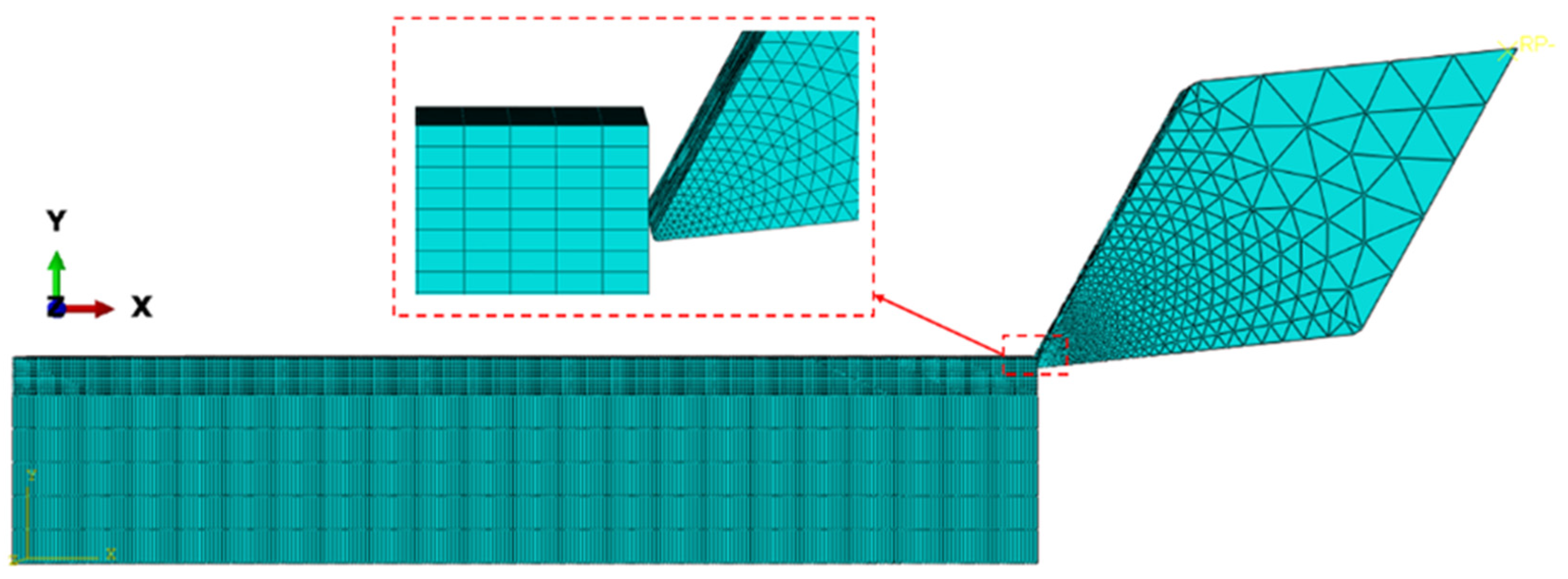
The workpiece size was 50 mm × 10 mm × 4 mm and was considered a deformable body. The tool was a diamond-shaped insert with a rake angle of 30° and a clearance angle of 5°. The edge radius of the insert was set to 10, 15, 20, 25, and 30 μm. The cutting speed was set to 0.6 m/min, and the cutting depth was set to 0.05 mm. The initial temperature was set to 20 °C. In this study, we disregarded the tool deformation during cutting and set the tool as a rigid body. The tool was meshed with free tetrahedral meshing, the workpiece was meshed with structural hexahedral meshing, the tool tip and cutting layer were encrypted, and the established 3D cutting model is shown in Figure 1.
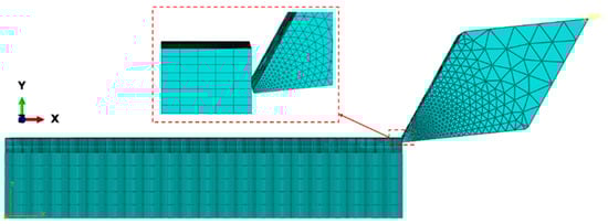
Figure 1.
3D cutting simulation model.
2.3. Simulation Results and Analysis
2.3.1. Effect of Edge Radius on Cutting Force
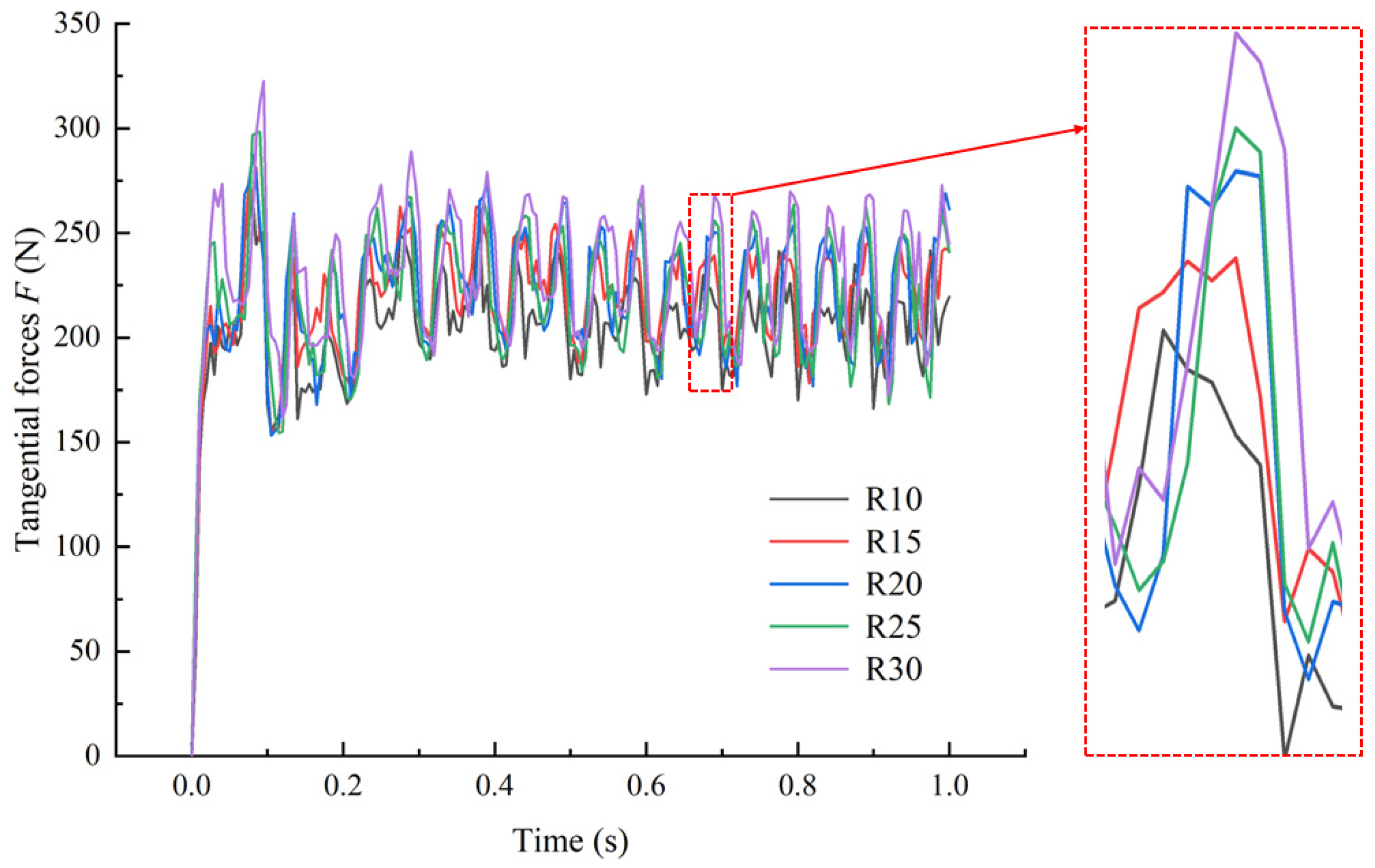
The tangential force of the tool is required to remove the workpiece material, and the cutting direction is also the feed direction; therefore, the tangential force of the tool is the focus of the cutting force analysis in this study. Figure 2 shows the inset tangential force curves for different cutting edge radii. In the initial cutting stage, the tool instantly impacted the workpiece, and the cutting force at the tip of the insert increased linearly. As the cutting entered a steady state, the cutting force decreased gradually before finally stabilizing within a small range. As shown in Figure 2, during the tool tip impact stage on the workpiece, the impact on the tip increased with an increase in the cutting edge radius. In the steady-state stage, the tool’s tangential force increased with increasing edge radius. The average value of the reaction force on the tool in the steady state stage was extracted, and the average tangential forces on the tool at different cutting edge radii were 200.7, 213.4, 214.9, 219.8, and 230.9 N, which were used to prepare for the comparative validation of the cutting experiments.
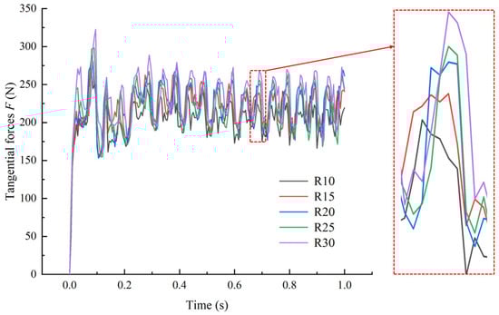
Figure 2.
Tangential force of tools under different cutting edge radii.
The analysis shows that as the cutting edge radius increases, the tangential force of the tool gradually increases. This phenomenon is mainly caused by the following reasons: on the one hand, a larger edge radius increases the bluntness of the tool, and the edge of the cutting area involved in cutting increases, generating a greater cutting force. On the other hand, a larger edge radius increases the contact area between the tip of the tool and the workpiece, increasing the friction between the tip of the tool and the chip. Therefore, the tangential force of the tool exhibits an increasing trend.
2.3.2. Effect of Edge Radius on Cutting Temperature
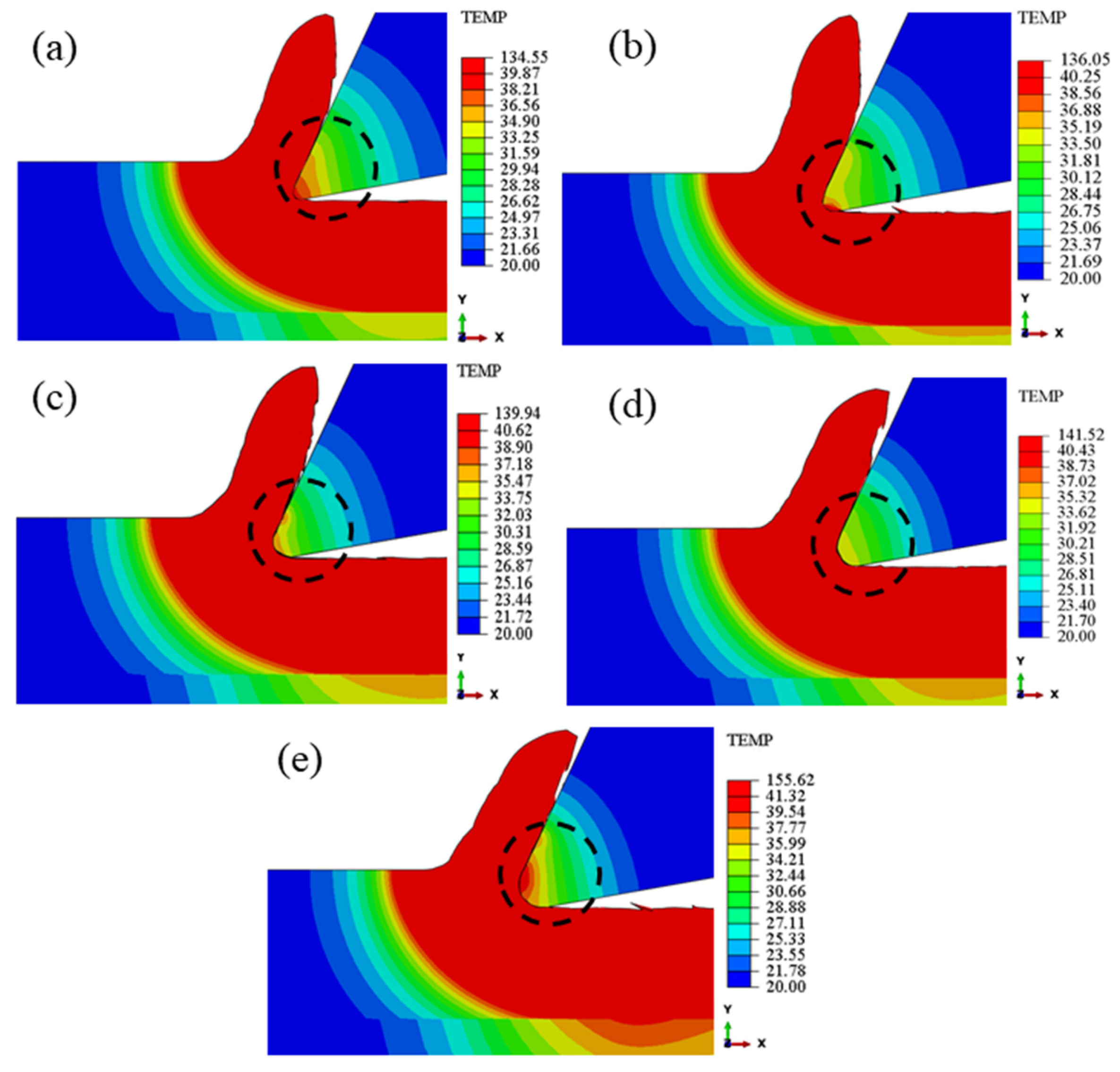
Figure 3 shows the distribution of the instantaneous cutting temperatures of the tool under different cutting edge radii during the stable cutting stage. Figure 3 dotted circle area shows that as the cutting edge radius increases, the high-temperature area of the cutting heat at the tool tip first decreases and then increases. This is because when the cutting edge radius increases from 10 to 25 μm, the heat dissipation capacity of the tool tip improves as the chip gradually stabilizes, resulting in the gradual transfer of the high-temperature area from the tool tip to the rake face. With a further increase in the cutting edge radius, the plastic deformation of the workpiece material and friction between the tool and chip increased during the cutting process. The cutting force on the tool tip increased the cutting heat generated by the tool tip. In general, this phenomenon can be attributed to the combined effect of tool-tip heat dissipation and cutting force.
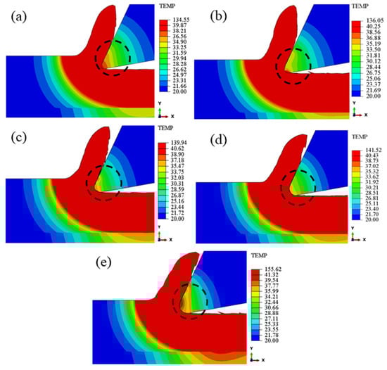
Figure 3.
Cutting temperature distribution of tools under different cutting edge radii: (a) 10 μm, (b) 15 μm, (c) 20 μm, (d) 25 μm, and (e) 30 μm.
The increasing trend of the peak temperature under different cutting edge radii against time is shown in Figure 4. As the cutting edge radius increased, the average values of the simulated cutting temperatures at the tool tip reached 26.8, 29.7, 30.2, 30.6, and 31.2 °C, and the maximum values reached 36.8, 36.9, 38.5, 39.2, and 44.0 °C, respectively. The analysis results show that both the average and maximum cutting temperatures at the cutting edge increase with time; however, due to the low feed rate of the tool, there was almost no difference in the temperature of the tip of the tool with different cutting edge radius, the maximum difference in the average cutting temperature with different cutting edge radius did not exceed 4.4 °C, and the maximum difference in the maximum cutting temperature did not exceed 7.2 °C. In general, the cutting edge radius has less effect on the cutting temperature.
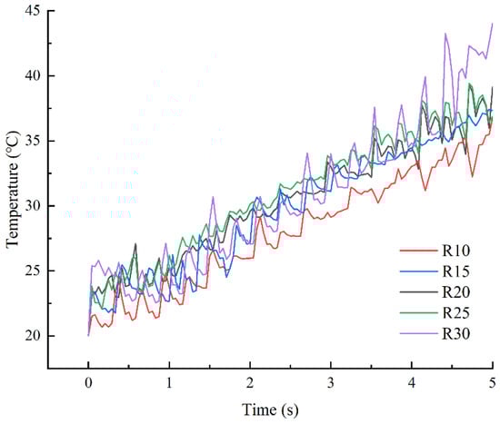
Figure 4.
Cutting temperature of tools under different cutting edge radii.
3. Experiment
3.1. Cutting Edge Preparation Principle by STP
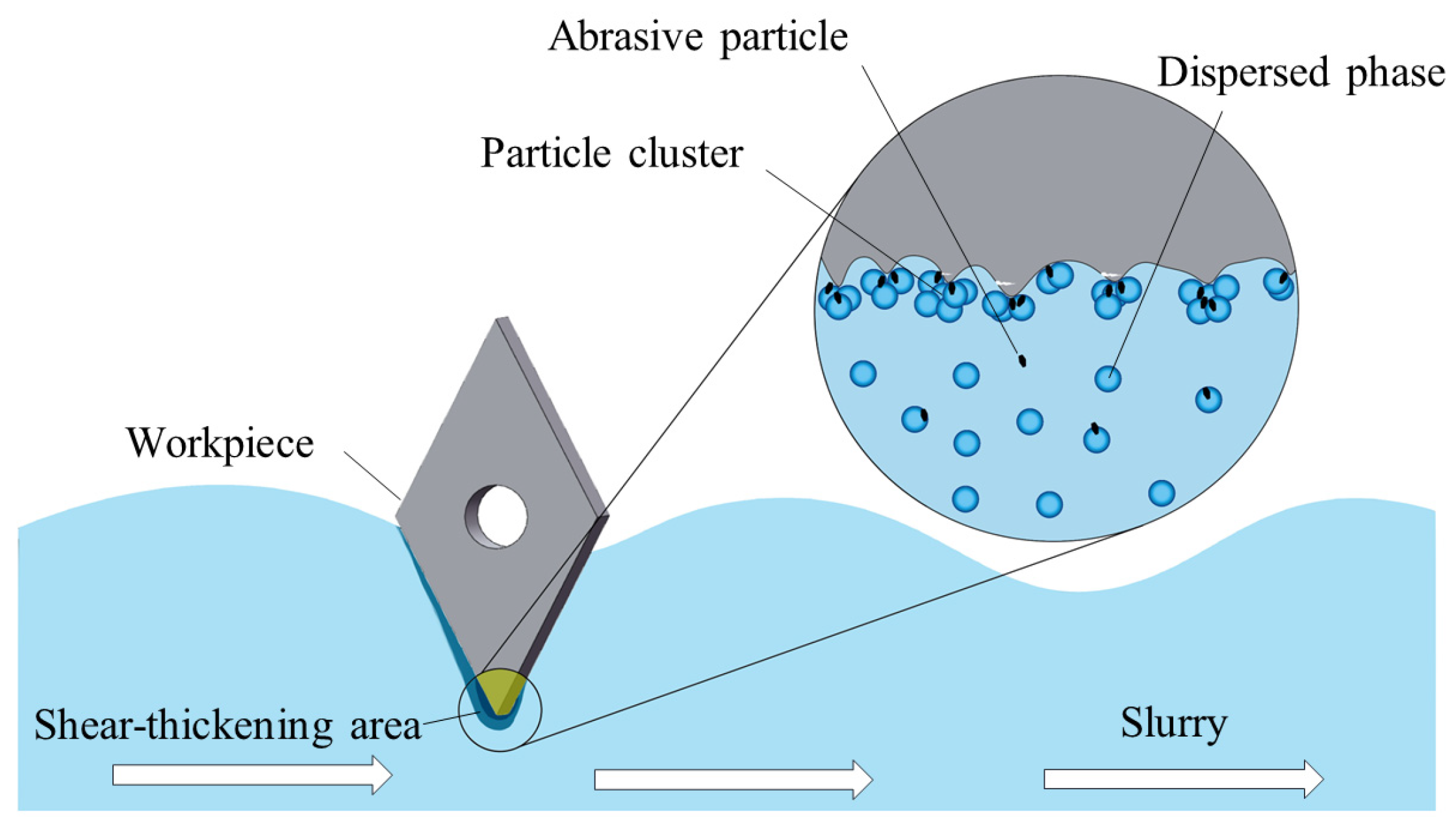
To ensure the consistency and uniformity of the tool edge preparation, an STP preparation method, as shown in Figure 5, was applied to prepare the carbide insert tips. In this study, the abrasives that removed the polished carbide material were uniformly dispersed in the polishing fluid using a non-Newtonian fluid with a shear-thickening effect as the base liquid. Shear thickening was induced by the relative motion between the insert fixed in the fixture and the polishing fluid. As the motion accelerated, the fluid viscosity in the tip contact area increased, resulting in the aggregation of solid particles in the dispersed phase to form clusters and enhancing the force on the abrasive particles. Consequently, a “flexible fixed abrasive” was formed around the tip of the insert, which can remove peaks and defects through continuous flexible polishing, ultimately polishing the cutting edge of the carbide insert.
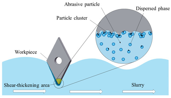
Figure 5.
Principle diagram of shear-thickening polishing for carbide inserts.
3.2. Characterization and Measurement of Cemented Carbide Insert
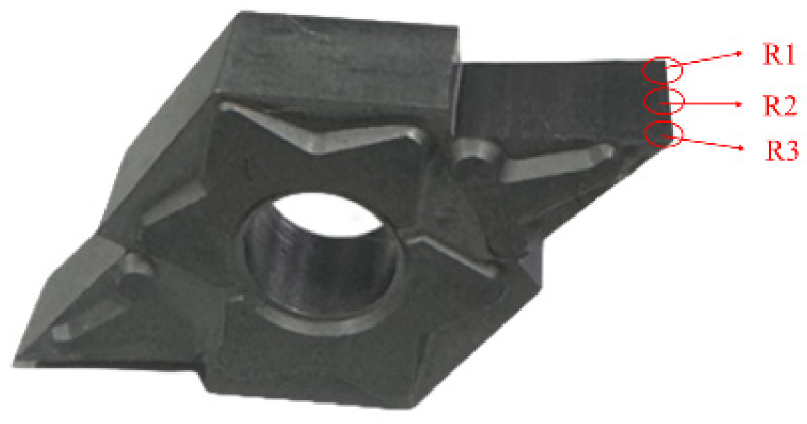
The rounded cutting edge radius of the carbide insert was measured using a tool edge gauge (Zoller-pom SkpGo). As shown in Figure 6, the different positions of the insert edge were labelled R1, R2, and R3. Measurements were taken at three points (R1, R2, and R3) on the cutting edge and averaged to obtain the cutting edge radius.
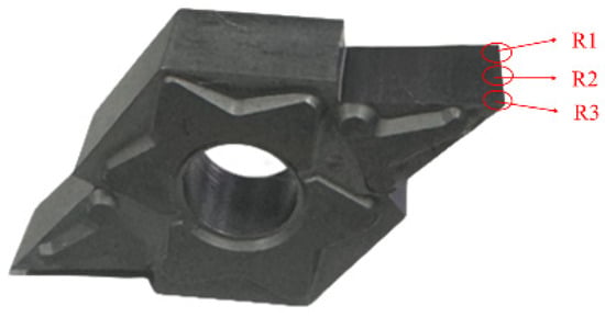
Figure 6.
Measuring positions of cutting edges.
To better evaluate the uniformity of the tool edge, a 3D topographic representation was plotted by combining 100 cross-sectional contours and measuring their cutting edge radii, as shown in Figure 7. The roughness of the rack face of the inserts was measured using a white light interferometer (Super View W1). The measurements were repeated three times at each measuring point, and the average value of the data was taken as the result. The surface morphology of the cutting edge was observed by scanning electron microscopy (SEM; IGMA, Zeiss, Germany).
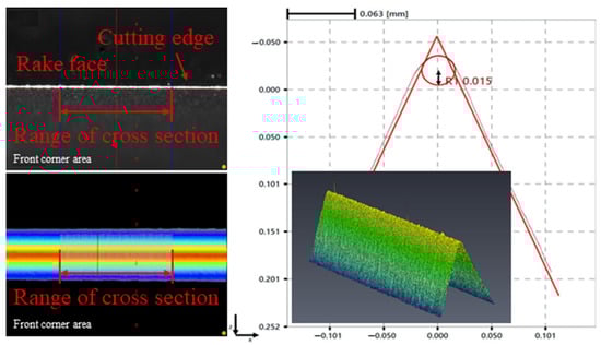
Figure 7.
Measurement of cutting edge radius.
3.3. Cutting Edge Preparation Experiment of Cemented Carbide Insert
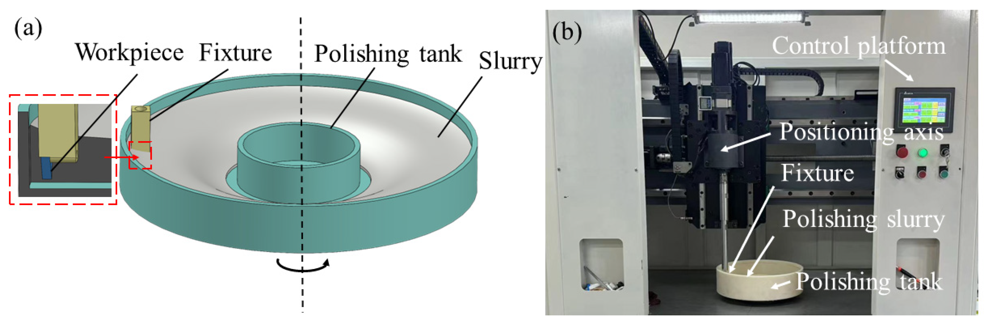
A schematic and experimental setup for the shear-thickening processing system are shown in Figure 8. Based on previous research [15], an optimal processing parameter combination was adopted with a polishing speed of 70 rpm, an abrasive size of 5000 #, and an abrasive concentration of 6 wt.%. To achieve uniform polishing, the insert edge was set parallel to the bottom of the polishing tank. The rounded cutting edge radius of the carbide insert was precisely controlled by varying the preparation time.
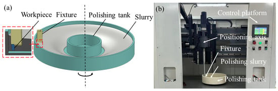
Figure 8.
STP experimental system: (a) schematic illustration; (b) photo of the experiment device.
3.4. Cutting Experiment
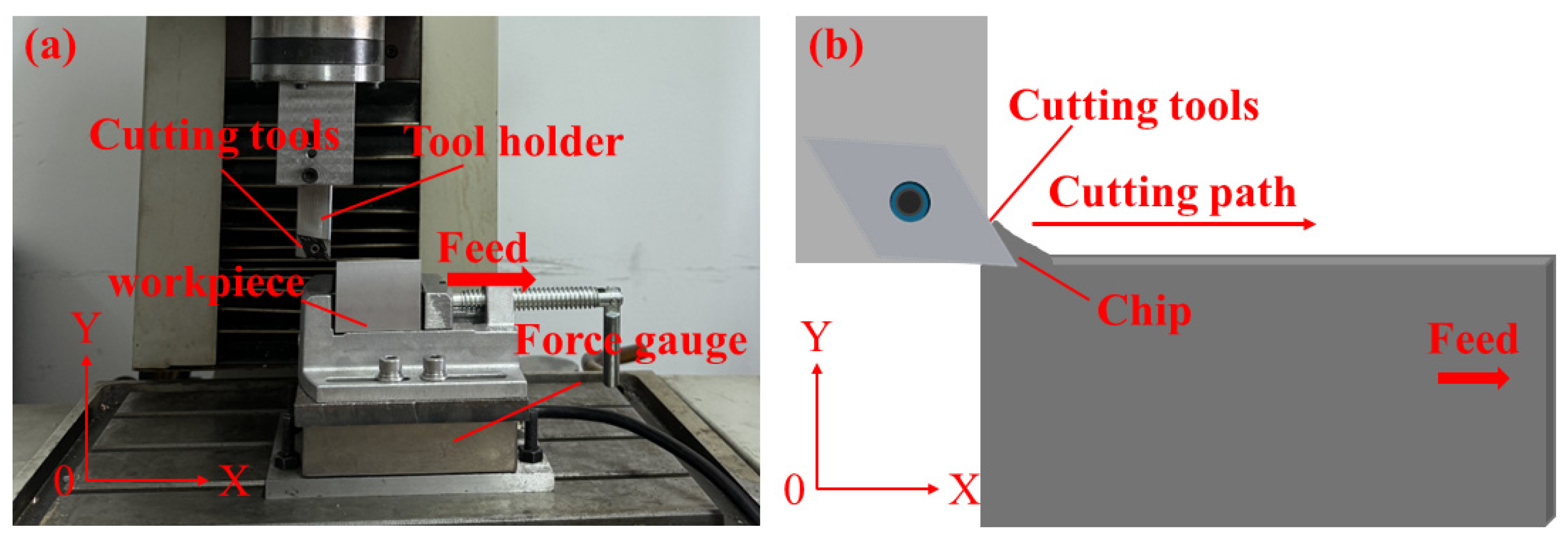
A cutting experiment on 6061 aluminum alloy with carbide inserts was conducted on a GCNC-CS-300 machine tool. To verify the simulation model more accurately, the workpiece size (50 mm × 10 mm × 4 mm) was consistent with the simulation. The experimental setup and schematics are shown in Figure 9a,b, respectively. The cutting parameters used in the experiments are listed in Table 3.

Figure 9.
(a) Experimental platform GCNC-CS-300; (b) cutting schematic illustration.
Table 3.
Cutting conditions.
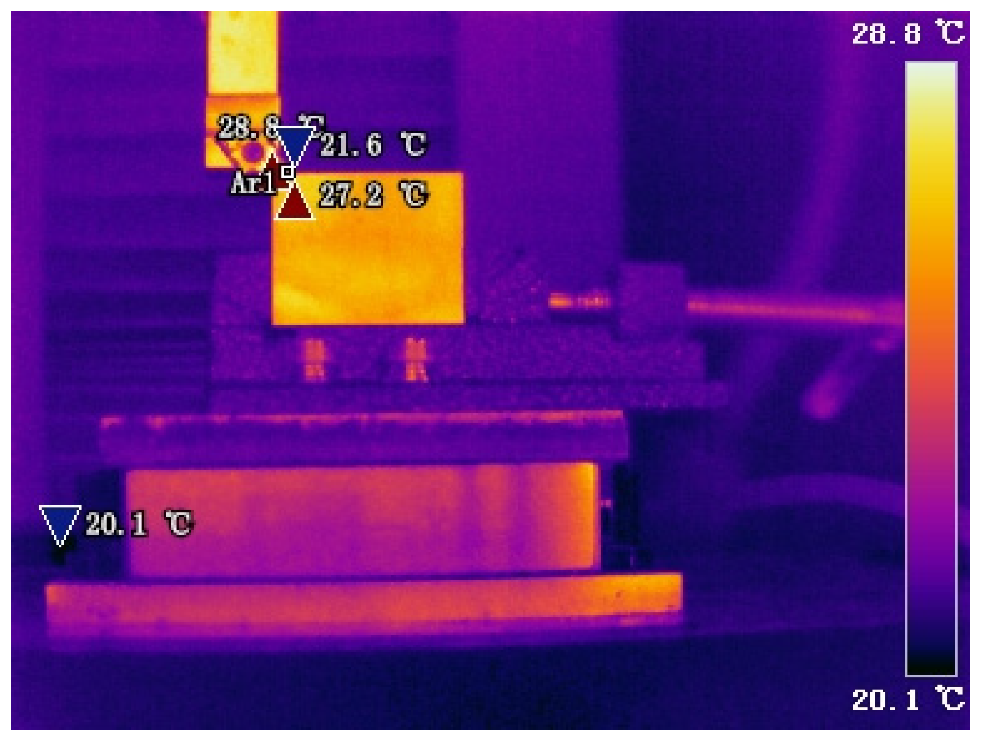
The cutting force in the experiment was measured using a three-axis force gauge (Shanghai Naichuang Test Technology Co., Ltd., Shanghai, China). The actual position of the force gauge is shown in Figure 9a; the force gauge was installed directly under the fixture. During the cutting process, the cutting temperature of the tool tip was measured using a thermal camera (Fotric 220s). The real-time cutting temperature cloud map obtained using a thermal camera is shown in Figure 10. The distance between the thermal camera and the cutting layer was kept at 0.5 m, and the shooting angle was 0°. The surface roughness and morphology of the machined workpiece were obtained using Talysurf i-Series (Taylor Hobson) and a super-depth-of-field microscope (VHX-100).

Figure 10.
Real-time cutting temperature cloud map.
4. Results and Discussion
4.1. Cutting Edge Preparation Experiment Results
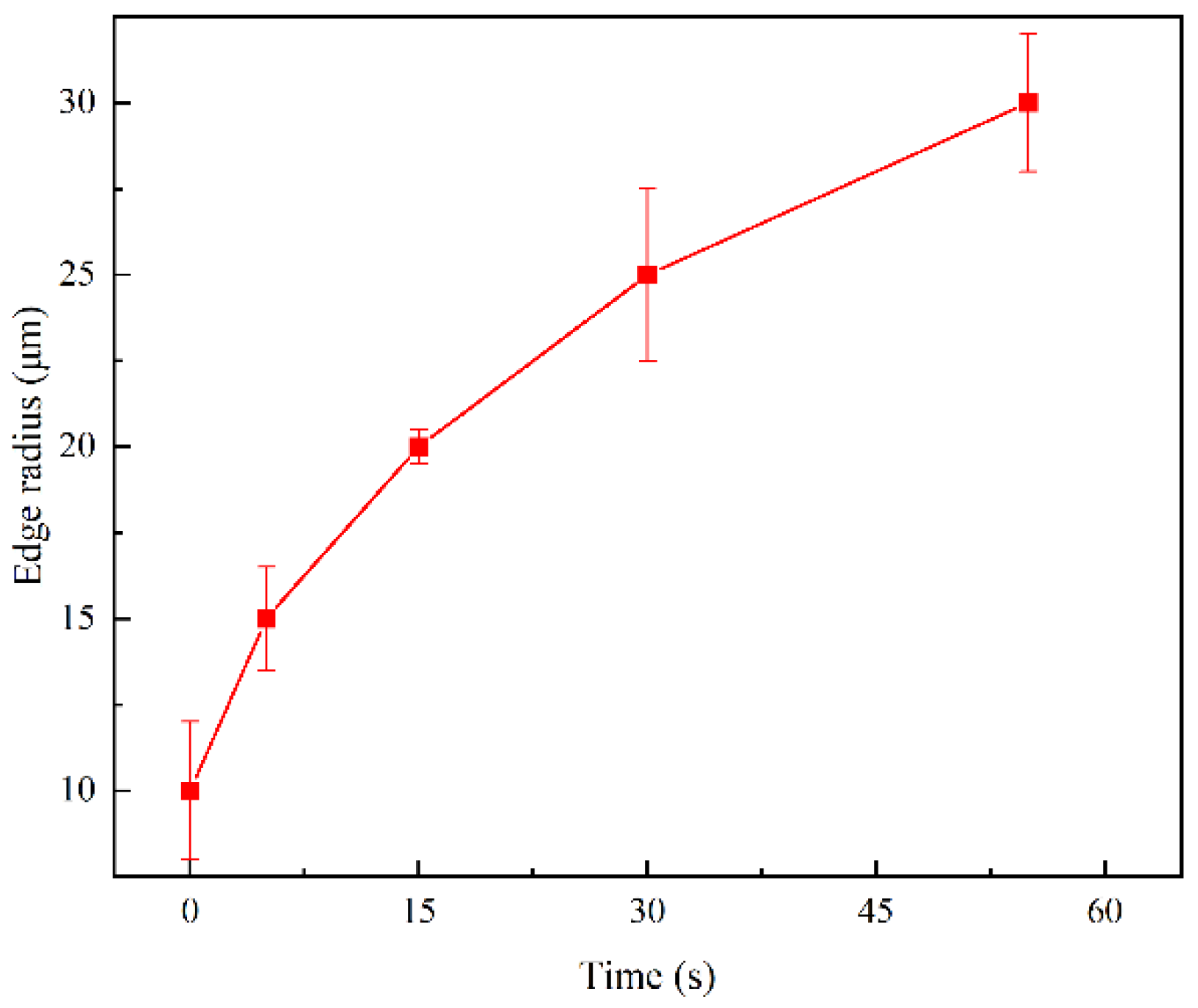
The initial cutting edge radius of the carbide insert was 10 ± 2 μm. As shown in Figure 11, with increasing polishing time, the edge radius in the insert increased gradually. This is because of the continuous material removal from the insert edge by the polishing slurry. The measurements of the cutting edge radius of the untreated insert and the four treated inserts are shown in Figure 12.

Figure 11.
Effect of polishing time on cutting edge radius.
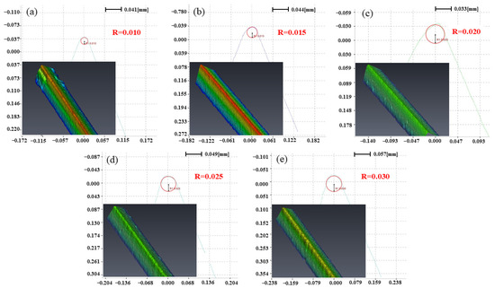
Figure 12.
Measurement results of the cutting edge radius: (a) 10 μm, (b) 15 μm, (c) 20 μm, (d) 25 μm, and (e) 30 μm.
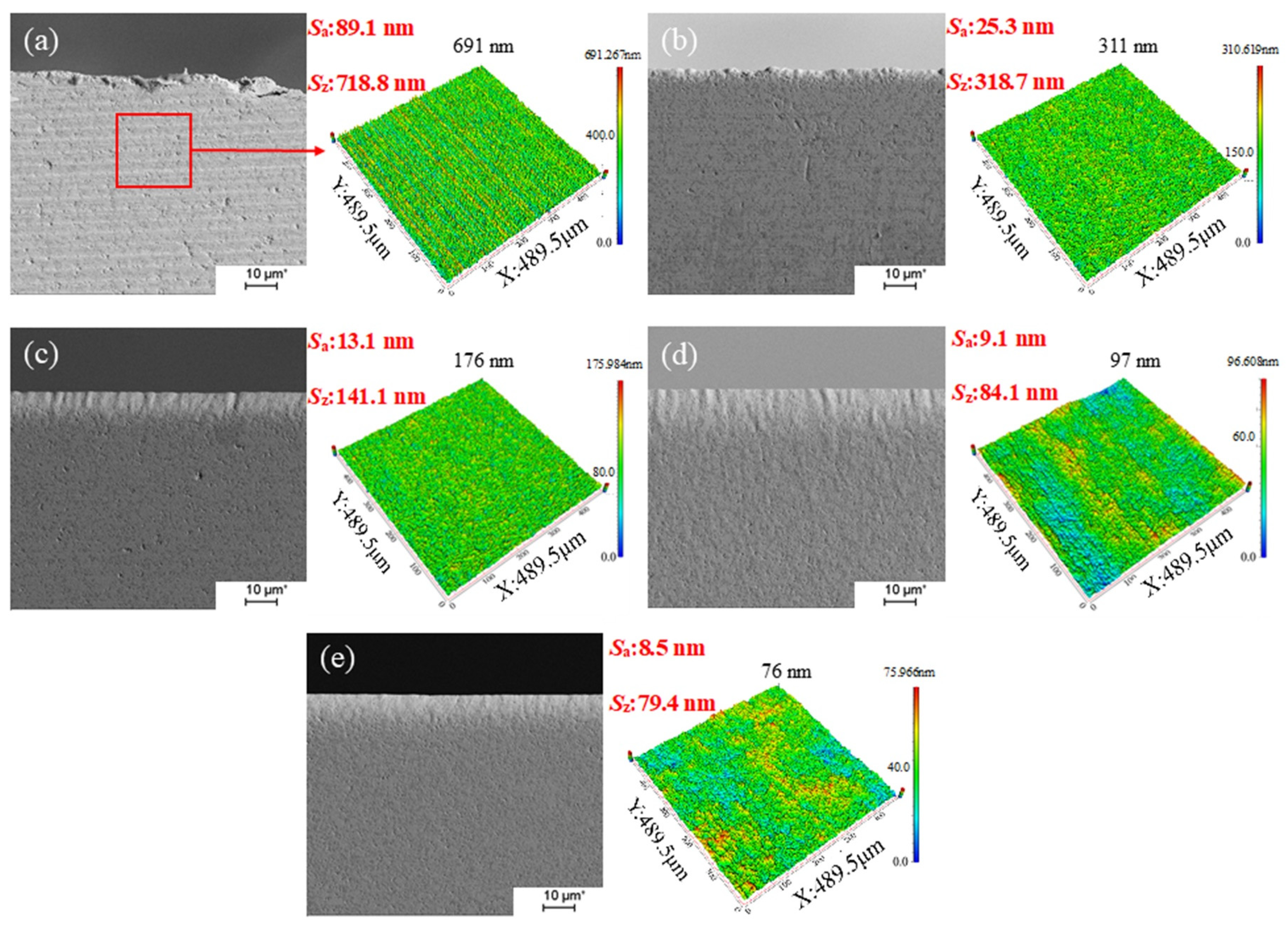
The frictional heat generation during the cutting process is analyzed in Section 2. During the cutting process, the surface quality of the insert edge and rake face affects the cutting force and heat, and high edge quality significantly reduces cutting heat and improves cutting quality. Therefore, it is necessary to observe the surface morphology of the cutting edge and rake face of inserts with different cutting edge radii. The observation results can provide support for the analysis of the cutting experiments. Edge topography measurements were performed for different edge radii and the SEM magnification was 500×, as shown in Figure 13. The red-framed area in Figure 13a shows the measurement area of the rake face. After the shear-thickening preparation treatment, the edge notch, burr, and other defects that existed in the initial insert edge were continuously eliminated, and the inserts with an edge radius within the range of 20–30 μm had smooth insert rake faces and essentially no edge defects.
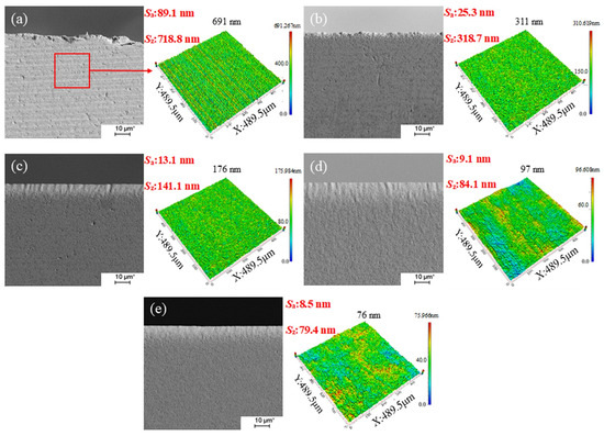
Figure 13.
The morphology and surface quality of tool edges under different cutting edge radii: (a) 10 μm, (b) 15 μm, (c) 20 μm, (d) 25 μm, and (e) 30 μm.
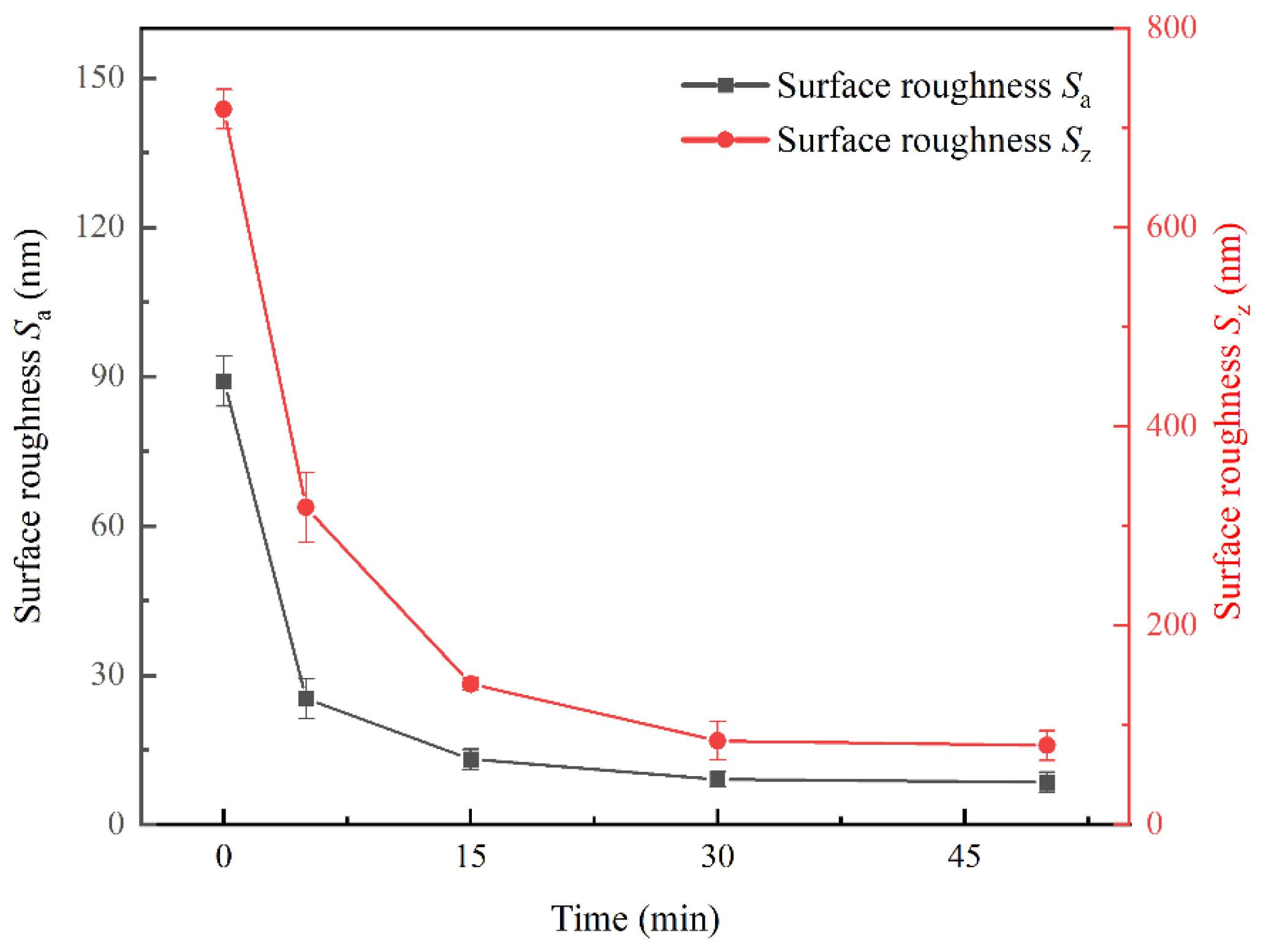
The relationship between the polishing time and the roughness of the rake face of the insert is shown in Figure 14. The initial rake faces Sa roughness of the cutting edge was 89.1 ± 10 nm, and the Sz roughness was 718.8 ± 160 nm. As the polishing time increased, the Sa and Sz roughness values of the cutter surfaces decreased. In the first 15 min of the preparation treatment, the Sa and Sz roughness of the tool face decreased significantly, proving that the protruding peaks and defects of the tool face were removed. When the preparation treatment time was in the range of 15–30 min, the Sa and Sz values of the tool face continued to decrease gradually. When the preparation treatment time was 30–50 min, the Sa roughness of the rake face of the tool was lower than 9.1 nm, and the Sz roughness was lower than 84.1 nm.
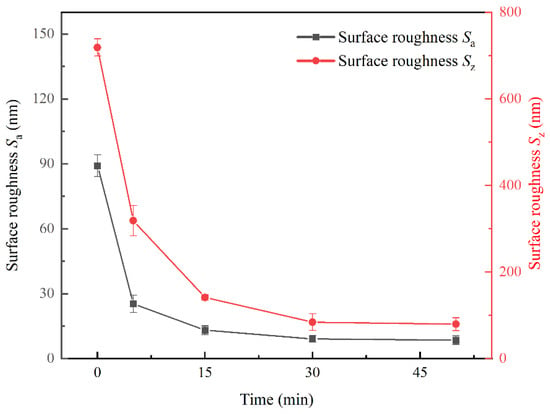
Figure 14.
Surface roughness of the cutting tool rake face under different cutting edge radii.
4.2. Cutting Experimental Results and Verification
4.2.1. Effect of Edge Radius on Cutting Force
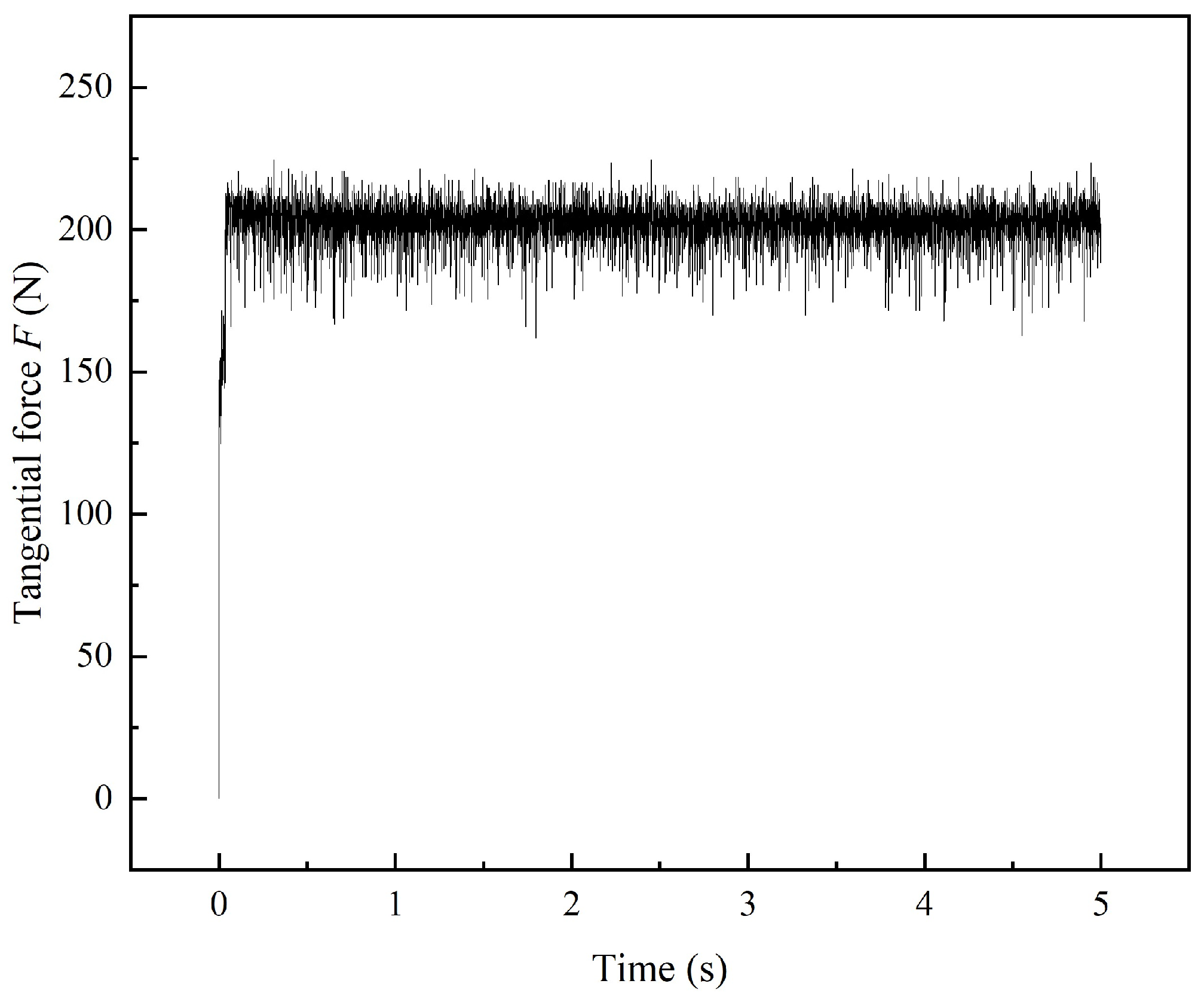
The curve of the tangential forces during the entire cutting time range is shown in Figure 15. The tangential force of the insert was kept in a stable range after 0.2 s. The cutting force data within the first 1 s of the cutting process were extracted and used to compare the simulation results.
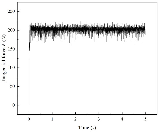
Figure 15.
Tangential forces during the entire cutting time range.
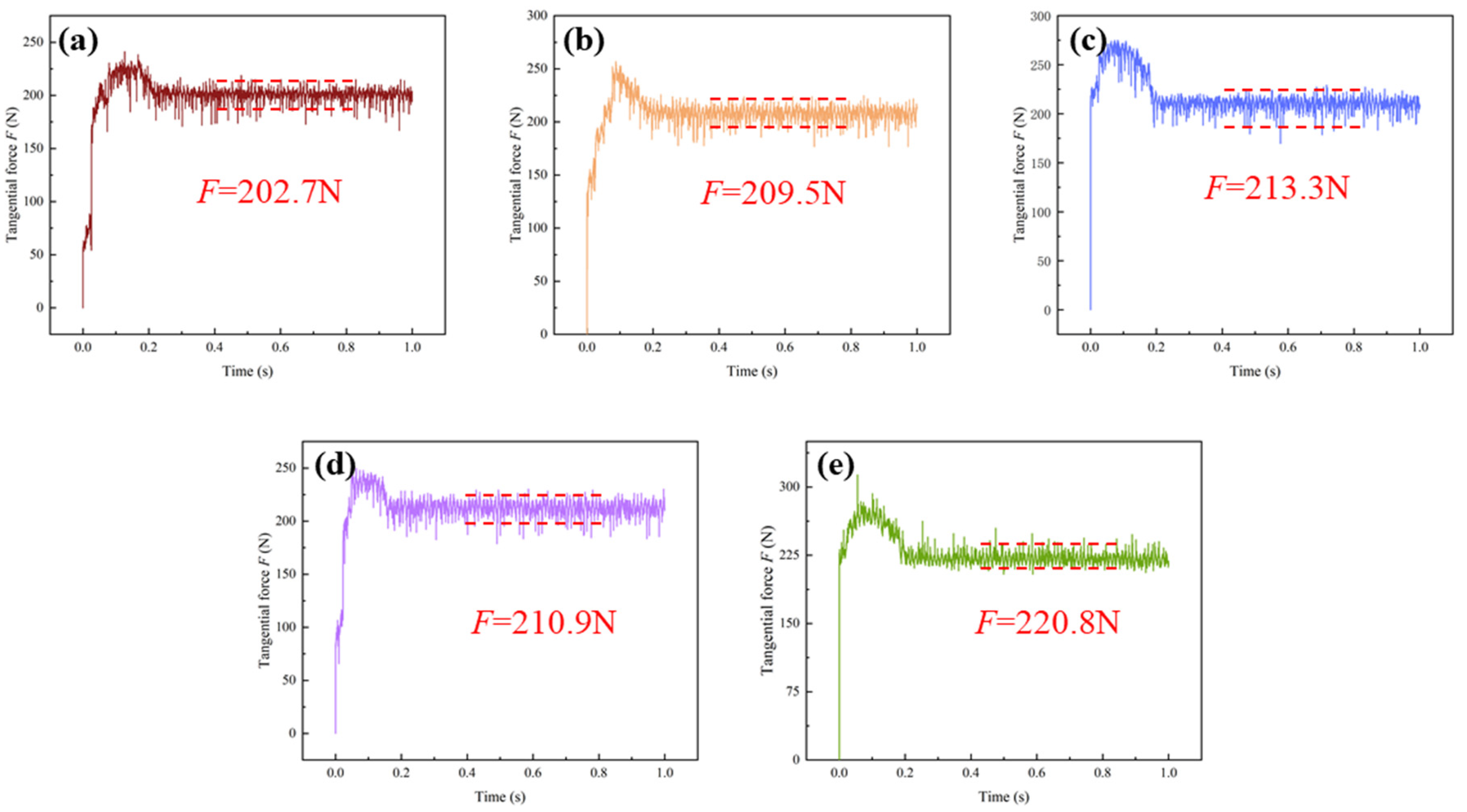
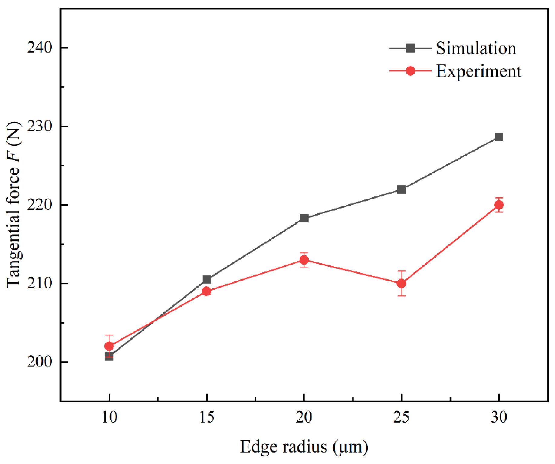
The curves of the cutting force of the insert over time for different cutting edge radii in the cutting experiments are shown in Figure 16. The tangential force trend over time aligns closely with the simulation results. Based on the simulation and experimental results, Figure 17 shows the relationship between the different cutting edge radii of the insert and the tangential force. As the cutting edge radius increased, the average values of simulated tangential force in steady state were 200.7, 213.4, 214.9, 219.8, and 230.9 N, and the average values of actual tangential force in steady state were 202.7, 209.5, 213.3, 210.9, and 220.8 N. The actual tangential force for the insert with a cutting edge radius of 10 μm was 2.0 N larger than the simulated value. This is because the defects and burrs on the edge of the untreated insert increased the resistance during cutting, resulting in a high tangential force. The actual tangential forces of the treated inserts were lower than the simulated values. This is because the preparation of the insert reduced the roughness of the cutting edge and rake face. The finish of the insert edge reduces the contact friction; thus, the actual tangential force of the insert was less than the simulated value. The actual tangential force of cutting edge radius of 25 μm was lower than the actual cutting force of the cutting edge radius of 20 μm. This is because the surface finish of the edge and rack face of the former is better than that of the latter, resulting in less friction between the tool and the chip. Although the tangential force increases with increasing obtuseness, the insert surface finish plays a dominant role in influencing the tangential force, so that the tangential force generally decreased when the cutting edge radius was 25 μm. The actual cutting force of the cutting edge radius in the interval of 25 ± 5 μm was 8.9 N less than the simulated value, with errors within 4.23% of the simulation data. The cutting force magnitude trends were approximately the same for both the cutting simulation and the experiment. In general, with an increase in the cutting edge radius of the insert, the actual cutting force value of the tool was smaller than that of the simulation results. A suitable preparation method can effectively reduce the friction of the cutting edge during the cutting process and reduce the cutting force on the cutting edge.

Figure 16.
Comparative results of the influence of different cutting edge radii on the cutting force: (a) 10 μm, (b) 15 μm, (c) 20 μm, (d) 25 μm, and (e) 30 μm.
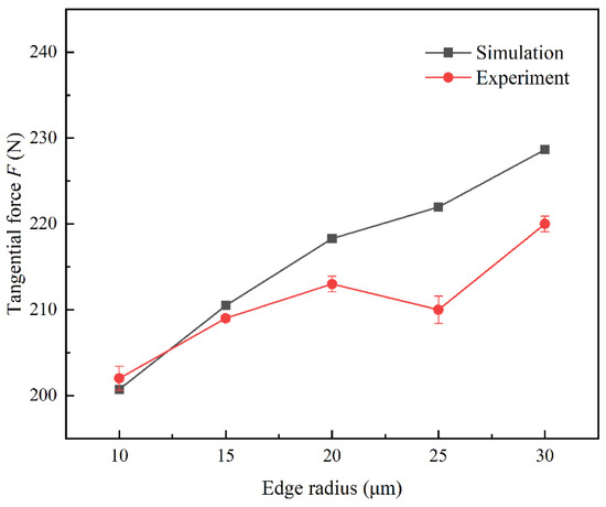
Figure 17.
Comparative results of the influence of different cutting edge radii on the cutting force.
4.2.2. Effect of Edge Radius on Cutting Temperature
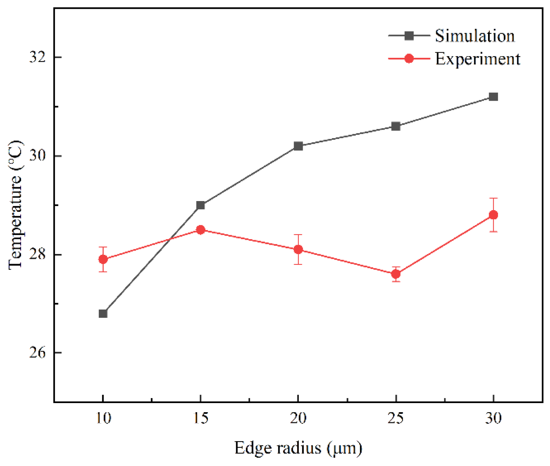
The simulation and experimental results for the cutting temperature of the insert tip under different cutting edge radii are shown in Figure 18. As the cutting edge radius increased, the average values of the simulated cutting temperature reached 26.8, 29.7, 30.2, 30.6, and 31.2 °C, and the average values of the actual cutting temperature reached 27.9, 28.5, 28.1, 27.5, and 28.8 °C. The actual average value of the cutting temperature of unprepared inserts was 1.1 °C higher than the simulated average value, and the actual average values of the cutting temperature of the prepared inserts were all lower than the simulated mean value. When the cutting edge radius was in the range of 25 ± 5 μm, the actual cutting temperature of the insert was lower than the simulated value, reaching 3.1 °C. First, owing to low-speed cutting and environmental factors, the variation in the heat of cutting observed during the actual cutting was small. Second, the poor edge quality of the unprepared insert leads to increased heat generation during cutting, whereas a decrease in the roughness of the rake face of the insert after preparation reduces heat generation during cutting. Furthermore, the maximum error in the average value of the cutting temperature at the tip of the insert was less than 10.1% when the cutting edge radius was 25 μm; therefore, the results of the cutting temperature in the simulation model are reliable.
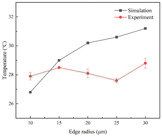
Figure 18.
The influence of different cutting edge radii on the cutting temperature.
4.2.3. Effect of Edge Radius on Cutting Quality
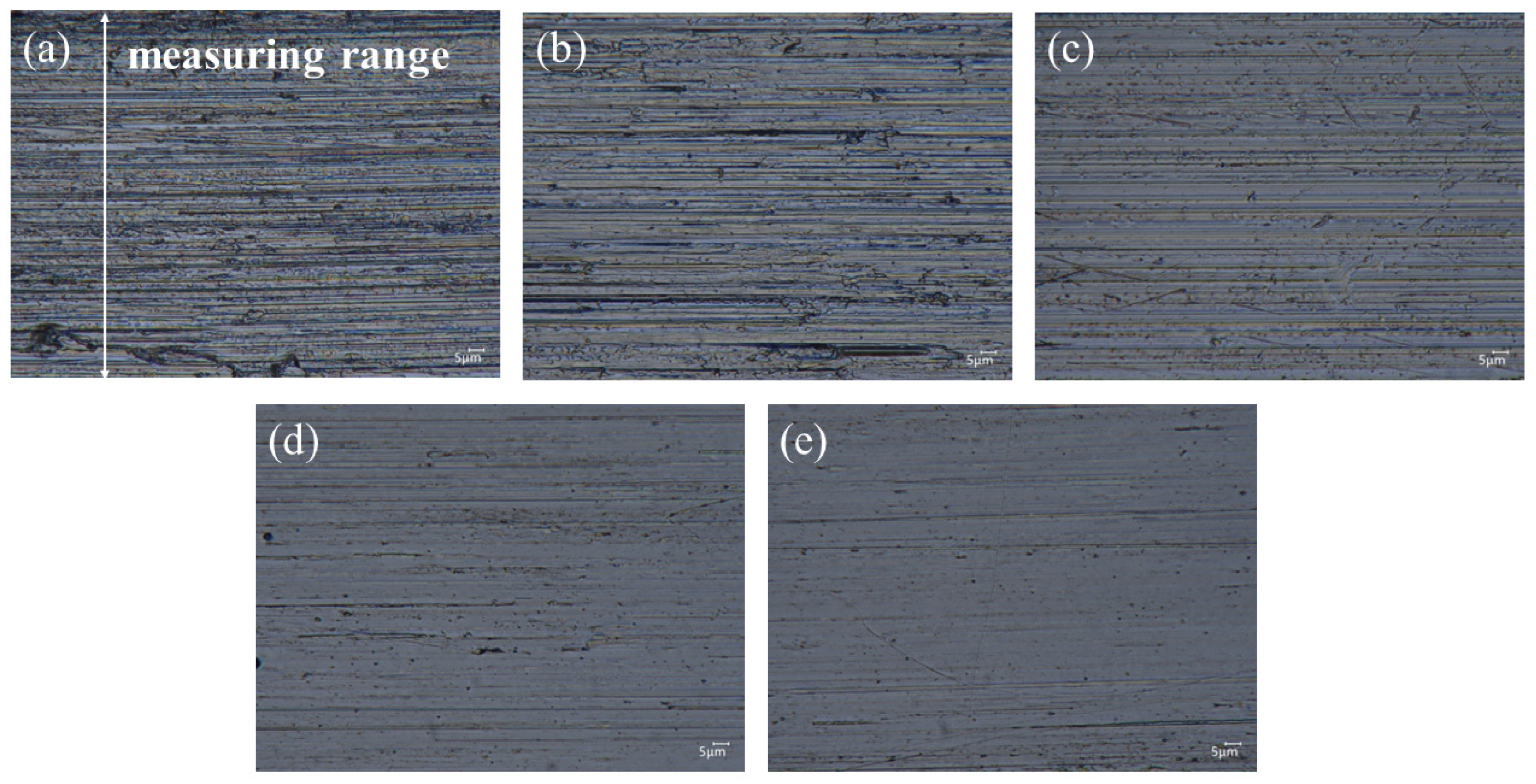
Figure 19 shows the surface morphology of the workpiece after cutting with carbide inserts. Figure 19a shows that the surface machined using the untreated insert had several pits owing to vibration and edge defects during cutting. When the cutting edge radius was in the range of 15–20 μm, the reduction in defects led to the reduction in impact-generated scratches. When the cutting edge radius was in the range of 25–30 μm, the edge defects were almost eliminated, improving edge uniformity, and the surface of the insert was uniform, allowing the tip arc to polish the workpiece better, which improved the stability of the cutting process. Therefore, the cutting edge radius and the surface quality will have a certain impact on the quality of the surface after cutting.
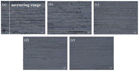
Figure 19.
Surface morphology of the workpieces under different cutting edge radii: (a) 10 μm, (b) 15 μm, (c) 20 μm, (d) 25 μm, and (e) 30 μm.
To analyze the impact of the degree of bluntness of the edge on the machining quality more intuitively, the measurement ranges of Ra and Rz roughness are shown in Figure 19a. Figure 20 shows the surface roughness measurement results for the insert edge at different cutting edge radii. Clearly, after the cutting edge preparation, the Ra and Rz of the machined surface show a decreasing trend with an increase in the cutting edge radius. When the cutting edge radius was in the range of 25–30 μm, the Ra and Rz roughness of the machined surface were both lower, with a reduction in Ra of 40.6–44.8% and in Rz of 46.6–50.7% compared to the machined surface of the untreated insert. In conclusion, the consistency and uniformity of the edge improved when the edge radius was in the range of 25–30 μm, which was more conducive to the improvement of the cutting performance of the tool. The roughness of the machined surface was significantly affected by the consistency and uniformity of the insert edge; the conducted research does not provide a clear idea as to how the edge rounding radius affects the cutting quality after cutting.
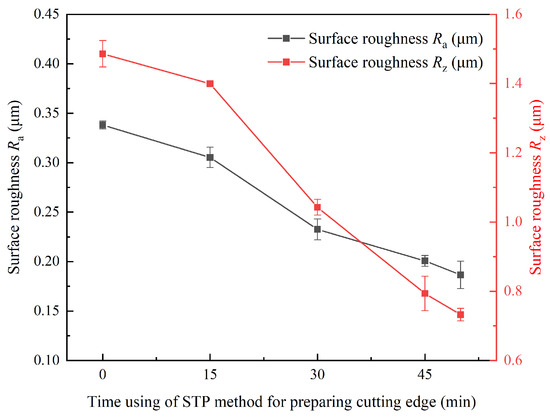
Figure 20.
Surface roughness of the workpieces under different cutting edge radii.
5. Conclusions
To investigate the effect of the cutting edge radius of the carbide insert on the cutting performance, cutting simulation and experiments were conducted on carbide inserts. The conclusions are as follows:
(1) In the cutting simulation, the insert tangential force increased from 200.7 to 230.9 N, and the average temperature of the insert tip increased from 26.8 to 31.2 °C with the increase in the cutting edge radius. The results show that both the insert tangential force and cutting temperature increased with an increase in the cutting edge radius.
(2) After the cutting edge preparation, the cutting edge radius was maintained at 10–30 μm, the Sa roughness of the rack face was reduced from 89.1 to 9.1 nm, and the Sz roughness was reduced from 718.8 nm to 84.1 nm.
(3) In the cutting experiments, the tangential force of the blade increased from 202.7 to 220.8 N, and the average temperature of the insert tip increased from 27.9 to 28.8 °C with the increase in the cutting edge radius. A comparison of the simulation results showed that the maximum error in the average value of the insert cutting force was less than 4.23%, and the maximum error in the average value of the insert cutting temperature was less than 10.1%. Therefore, the cutting simulation model was reliable.
(4) Predicting the cutting performance of cemented carbide inserts using simulation methods can clarify the target interval of this type of tool cutting edge preparation. This method can improve the efficiency of cutting edge preparation and reduce research costs. In addition, the impact of cutting edge radius on machining quality should be a focus of scholars’ research in the future.
Author Contributions
Conceptualization, S.C., Z.B. and X.W.; methodology, S.C., Z.B., Y.Y. and X.W.; software, S.C., W.Z. and B.L.; validation, S.C., Z.B., Y.Y. and X.W.; investigation, S.C., J.Y. and H.C.; data curation, S.C., Z.B., Y.Y. and W.H.; writing—original draft preparation, S.C.; writing—review and editing, S.C., Z.B., J.W. and X.W.; supervision, S.C.; project administration, S.C.; funding acquisition, S.C. All authors have read and agreed to the published version of the manuscript.
Funding
This research was supported by National Natural Science Foundation of China (52175441, 51805485, U20A20293, 52175442, 52275467); Zhejiang Provincial Natural Science Foundation of China (LY21E050010).
Data Availability Statement
The original contributions presented in the study are included in the article, further inquiries can be directed to the corresponding author.
Conflicts of Interest
The authors declare no conflicts of interest. The funders had no role in the design of the study; in the collection, analyses, or interpretation of data; in the writing of the manuscript; or in the decision to publish the results.
References
- Yuan, X.M.; Cao, W.J.; Zhang, G.; Wang, G.X.; Zhou, J.; Tang, Z.M. Construction of cutting force prediction model of honeycomb core with dagger knife. Manuf. Tech. Mach. Tools 2021, 9, 79–85. [Google Scholar]
- Barbosa, M.G.C.B.; Hassui, A.; De Oliveira, P.A.; Borges, W.F.A. Influence of feed and cutting-edge radius on tool wear, surface roughness, and electric current in milling of VP20TS steel. Int. J. Adv. Manuf. Technol. 2023, 129, 3609–3626. [Google Scholar] [CrossRef]
- Fulemova, J.; Janda, Z. Influence of the Cutting Edge Radius and the Cutting Edge Preparation on Tool Life and Cutting Forces at Inserts with Wiper Geometry. Procedia Eng. 2014, 69, 565–573. [Google Scholar] [CrossRef]
- Gonçalves Júnior, M.; de Angelo Sanchez, L.E.; França, T.V.; Fortulan, C.A.; Da Silva, R.H.L.; Foschini, C.R. Analysis of the tool nose radius influence in the machining of a green ceramic material. Int. J. Adv. Manuf. Technol. 2019, 105, 3117–3125. [Google Scholar] [CrossRef]
- Peter, P.; Boris, P.; Tomáš, V.; Jozef, P.; Marek, V.; Vladimír, Š. Cutting edge radius preparation. Mater. Today Proc. 2020, 22, 212–218. [Google Scholar] [CrossRef]
- Zhang, S.; Zou, B.; Liu, Y.; Wang, Y.; Huang, C.; Liu, Z. Edge preparation and quality of carbide cutting inserts treated by wet micro-abrasive blasting. Int. J. Adv. Manuf. Technol. 2018, 96, 2307–2318. [Google Scholar] [CrossRef]
- Deng, Q.; Dong, R.; Sun, L.; Zhang, C.; Lyu, B.; Wang, X.; Yuan, J. Edge preparation of carbide cutting tool based on abrasive water jet of fluid self-excited oscillating characteristics. Int. J. Adv. Manuf. Technol. 2023, 129, 2661–2676. [Google Scholar] [CrossRef]
- Hartig, J.; Kirsch, B.; Aurich, J.C. Analysis of the grinding wheel wear and machining result during cutting edge preparation with elastic bonded grinding wheels. J. Manuf. Process. 2022, 75, 181–202. [Google Scholar] [CrossRef]
- Li, X.; Huang, X.; Ming, Y.; Zhou, D.D.; Cai, Y.H. Carbide twist drill surface polishing and cutting edge passivating based on magnetic field-assisted shear thickening. Int. J. Adv. Manuf. Technol. 2023, 126, 5649–5664. [Google Scholar] [CrossRef]
- Fu, X.; Zou, B.; Liu, Y.; Huang, C.; Yao, P. Edge micro-creation of Ti (C, N) cermet inserts by micro-abrasive blasting process and its tool performance. Mach. Sci. Technol. 2019, 23, 951–970. [Google Scholar] [CrossRef]
- Chen, H.Y.; Wu, Z.C.; Hong, B.B.; Hang, W.; Zhang, P.; Cao, X.; Xu, Q.; Chen, P.; Chen, H.; Yuan, J.; et al. Study on the affecting factors of material removal mechanism and damage behavior of shear rheological polishing of single crystal silicon carbide. J. Manuf. Process. 2024, 112, 225–237. [Google Scholar] [CrossRef]
- Li, M. Basic Research on Shear Thickening and Polishing Methods. Ph.D. Thesis, Hunan University, Changsha, China, 2015. [Google Scholar]
- Wang, L.; Wu, M.X.; Chen, H.Y.; Hang, W.; Wang, X.; Han, Y.; Chen, H.; Chen, P.; Beri, T.H.; Luo, L.; et al. Damage evolution and plastic deformation mechanism of preparation layer during shear rheological polishing of polycrystalline tungsten. J. Mater. Res. Technol. 2024, 28, 1584–1596. [Google Scholar] [CrossRef]
- Lyu, B.; Ke, M.; Fu, L.; Duan, S.; Shao, Q.; Zhou, Y.; Yuan, J. Experimental study on the brush tool–assisted shear-thickening polishing of cemented carbide insert. Int. J. Adv. Manuf. Technol. 2021, 115, 2491–2504. [Google Scholar] [CrossRef]
- Shao, L.Y.; Ke, M.F.; Wang, J.H.; Lyu, B.H.; Wang, X.; Yuan, J.L. Experimental study on flexible fiber assisted stress rheological preparation and polishing of complex edge of cemented. Diam. Abras. Eng. 2022, 42, 1–9. [Google Scholar]
- Chan, J.; Koshy, P. Tool edge honing using shear jamming abrasive media. CIRP Ann. 2020, 69, 289–292. [Google Scholar] [CrossRef]
- Shao, W.P.; Zhang, T.P. Process parameters optimization of high-speed milling 7075 aluminum alloy with nano-diamond coated tool. Diam. Abras. Eng. 2022, 42, 473–480. [Google Scholar]
- Zhang, X.; Cheng, Y.; Lv, M.; Miao, X.; Xie, C. Study on high-speed vibration cutting of titanium alloy considering cutting edge radii. Int. J. Adv. Manuf. Technol. 2023, 124, 3327–3342. [Google Scholar] [CrossRef]
- Ma, H.; Tang, A.; Xu, S.; Li, T. Finite element simulation of bending thin-walled parts and optimization of cutting parameters. Metals 2023, 13, 115. [Google Scholar]
- Sahoo, P.; Patra, K.; Singh, V.K.; Gupta, M.K.; Song, Q.; Mia, M.; Pimenov, D.Y. Influences of TiAlN coating and limiting angles of flutes on prediction of cutting forces and dynamic stability in micro milling of die steel (P-20). J. Mater. Process. Technol. 2020, 278, 116500. [Google Scholar] [CrossRef]
- Kabwe, E.; Karakus, M.; Chanda, E.K. Isotropic damage constitutive model for time-dependent behaviour of tunnels in squeezing ground. Comput. Geotech. 2020, 127, 103738. [Google Scholar] [CrossRef]
- Xu, Z.; Song, Y.; Liu, Z. Stress analysis and fatigue life prediction of contact wire located at steady arms in high-speed railway catenary system. IEEE Trans. Instrum. Meas. 2022, 71, 1–12. [Google Scholar] [CrossRef]
- Shen, W.; Xue, F.; Li, C.; Liu, Y.; Mo, X.; Gao, Q. Study on constitutive relationship of 6061 aluminum alloy based on Johnson–Cook model. Mater. Today Commun. 2023, 37, 106982. [Google Scholar] [CrossRef]
- Sirigiri, V.K.R.; Gudiga, V.Y.; Gattu, U.S.; Suneesh, G.; Buddaraju, K.M. A review on Johnson Cook material model. Mater. Today Proc. 2022, 62, 3450–3456. [Google Scholar] [CrossRef]
- Gurusamy, M.; Sriram, S. Investigations on the choice of Johnson–Cook constitutive model parameters for the orthogonal cutting simulation of inconel 718. J. Adv. Manuf. Syst. 2023, 22, 1–25. [Google Scholar] [CrossRef]
- Javidikia, M.; Sadeghifar, M.; Songmene, V.; Jahazi, M. On the impacts of tool geometry and cutting conditions in straight turning of aluminum alloys 6061-T6: An experimentally validated numerical study. Int. J. Adv. Manuf. Technol. 2020, 106, 4547–4565. [Google Scholar] [CrossRef]
- Akram, S.; Jaffery, S.H.I.; Khan, M.; Fahad, M.; Mubashar, A.; Ali, L. Numerical and experimental investigation of Johnson–Cook material models for aluminum (Al 6061-T6) alloy using orthogonal machining approach. Adv. Mech. Eng. 2018, 10, 1–14. [Google Scholar] [CrossRef]
- Zhuang, K.; Fu, C.; Weng, J.; Hu, C. Cutting edge microgeometries in metal cutting: A review. Int. J. Adv. Manuf. Technol. 2021, 116, 2045–2092. [Google Scholar] [CrossRef]
- Peng, B.Y.; Xu, D.; Wang, P.J. Simulation Effect of Tool Material and Angle on Cutting Force of 7075-T6 Aluminum Alloy. Tool Technol. 2023, 57, 131–134. [Google Scholar]


Disclaimer/Publisher’s Note: The statements, opinions and data contained in all publications are solely those of the individual author(s) and contributor(s) and not of MDPI and/or the editor(s). MDPI and/or the editor(s) disclaim responsibility for any injury to people or property resulting from any ideas, methods, instructions or products referred to in the content. |
© 2024 by the authors. Licensee MDPI, Basel, Switzerland. This article is an open access article distributed under the terms and conditions of the Creative Commons Attribution (CC BY) license (https://creativecommons.org/licenses/by/4.0/).