Abstract
This paper presents the possibility of using additional ballistic shields based on composite materials, which are applied to the body of a passenger car. A ballistic laminate made of Twaron T 750 aramid fabric with 5 mm thick and 2 mm thick magnetic foil was used. In the first stage, the mechanical parameters of the tested ballistic laminate system were determined in tensile tests. In field tests, the considered system was analyzed in terms of impact with a 9 × 19 mm FMJ Parabellum projectile, and then the results were numerically verified. The work was focused on the validation of numerical models. The appropriate correlation level of the numerical results was obtained with the fit, which was estimated at approximately 7%; furthermore, the results prove the correctness of this study’s research methodology.
1. Introduction
For years, safety has been a crucial consideration for designers during the vehicle design stage, especially when transporting objects that are sensitive to external factors, particularly people. Phenomena observed in recent years, such as the rise in the number of mass shootings worldwide [1] and the escalation of subsequent armed conflicts, like the Iraq War or Russia’s aggression against Ukraine, increasingly emphasize the necessity to equip not only military vehicles, but also civilian passenger vehicles [2,3].
In the event of exposure to firearms, a standard car is insufficient to protect the passengers. For this purpose, specialized vehicles are constructed, using materials with suitable strength properties. The materials commonly used for this purpose are composites reinforced with aramid fibers of the Kevlar® or Twaron® type, composites with ultra-high molecular weight polyethylene (UHMWPE) of the Spectra® or Dyneema® type, and composites combined with ceramics. In addition to their high energy-intensive properties, another benefit is the high availability of these materials on the European market, and the possibility of obtaining them artificially [4,5,6].
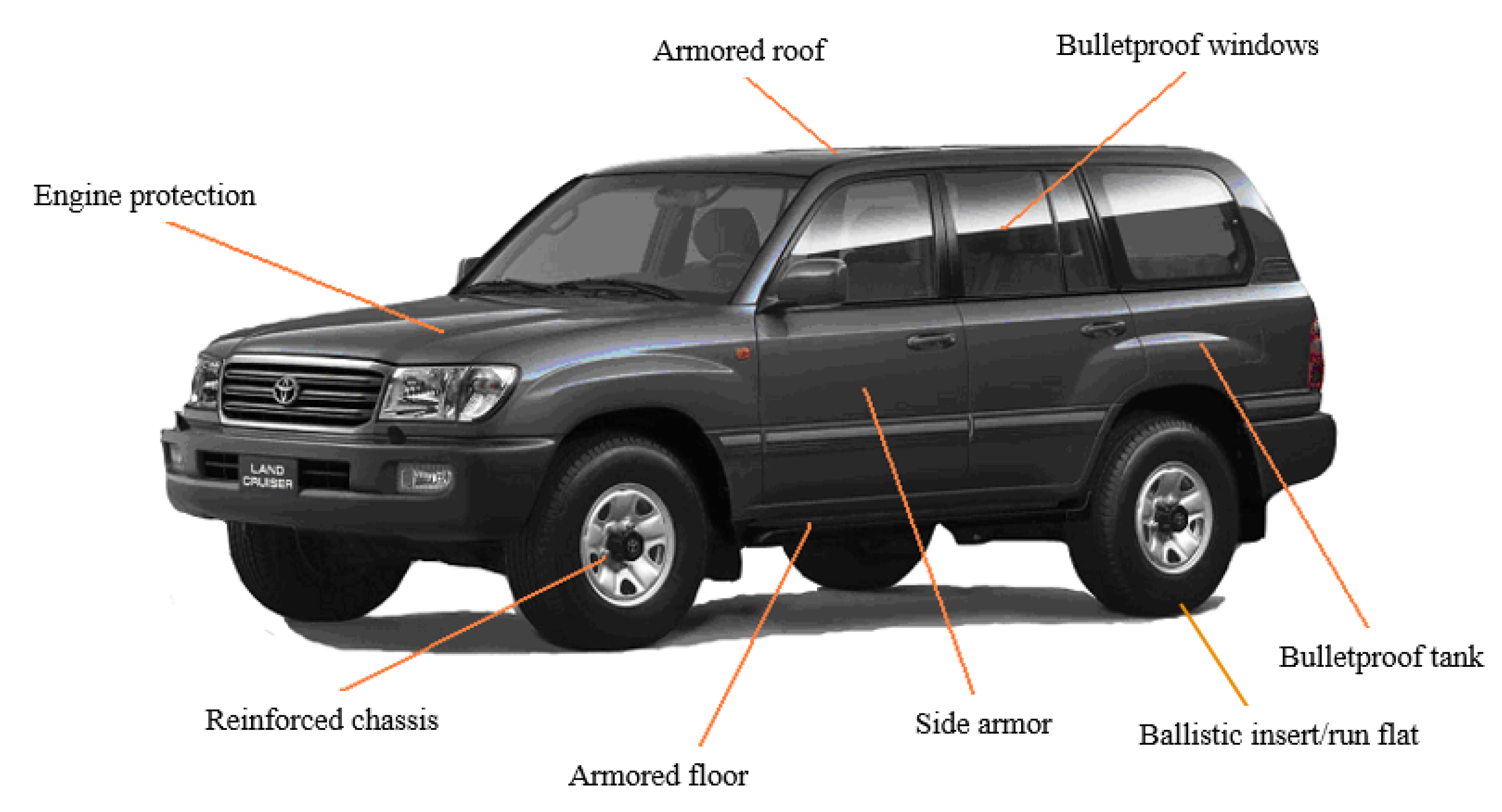
Most often, the entire structure of the car is subordinated to the adaptation to bullet resistance (Figure 1). However, gunfire is often directed only at specific areas of the car body, particularly those behind which a person is in the closest proximity, such as a car door. This implies that only part of the vehicle can be retrofitted, not the entire vehicle, with direct implications on saving weight and costs. This type of solution is used by DEW in police cars, wherein the ballistic package is mounted inside the vehicle door [7]. Another solution proposed by Scanfiber is to install bulletproof linings using multifunctional strips [8]. However, these are methods that entail the need for mechanical intervention in the door structure (e.g., drilling additional holes). The methodology described in this article refers to the power of a magnetic foil on the vehicle body. Based on the analysis carried out in this work [9], it was assumed that the most optimal solution for quick and efficient application in civilian vehicles would be the use of a composite reinforced with aramid fibers.

Figure 1.
General view of the armor of a civilian vehicle.
To ensure an adequate level of protection of the life and health of vehicle users, ballistic shields are subject to specific requirements, which are included in relevant international or national standards. Constructed facilities [10] must respect strict criteria to ensure the safety of people in these vehicles. The armor technology used is an individual development line, guarded by individual companies [11]. The published literature in this area refers to the general principles included in the range of FB2 to FB7 of the CEN 1522 standard [12].
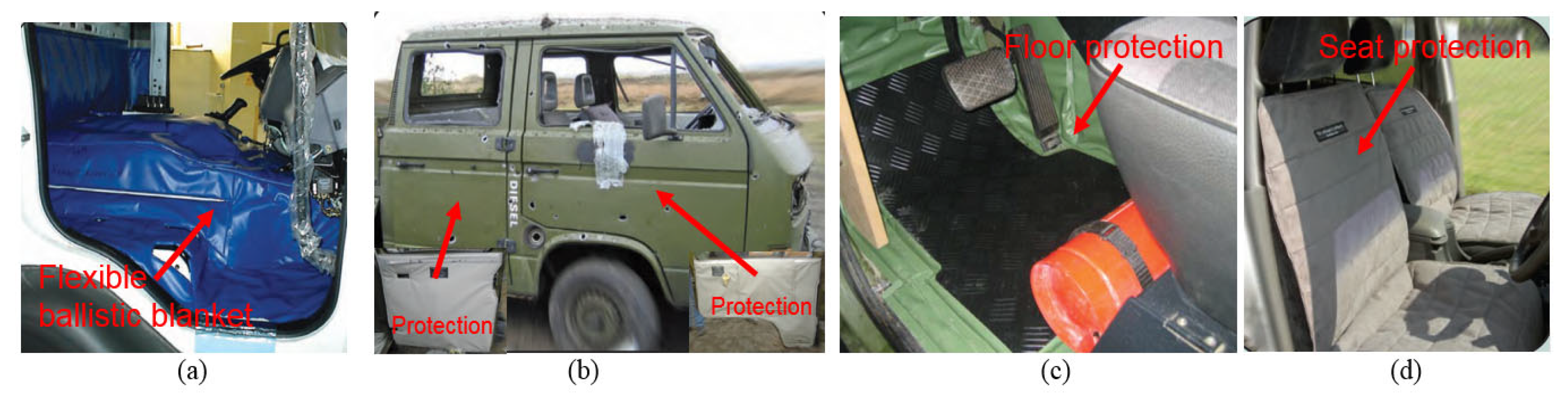
Ballistic protection inside the car, located between the body and upholstery, is commonly used. However, many manufacturers also offer unconventional reinforcements in the form of spall liner for crew compartments. Reinforcements are used for a multifunctional protection system, designed to be placed above the driver/crew to provide protection against fragments of various types of explosive devices or small arms ammunitions. Such solutions may include, for example, flexible ballistic blankets that are adapted to a specific vehicle and can be installed within a few hours. Other protection types can be implemented by considering the form of appropriate material geometries for seat protection, as part of personal protection, covering the back and lower body from fragments of small, anti-personnel mines, hand grenades and guns. An example of various solutions is shown in Figure 2.
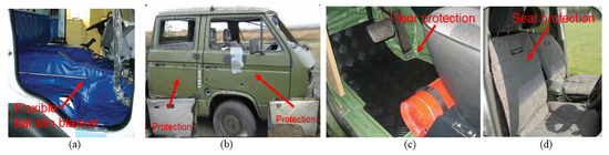
Figure 2.
Examples of ad hoc applications of ballistic protection reinforcement: (a) protection of the interior of the vehicle cabin; (b) use of spall liner; (c) explosion-proof reinforcement of the vehicle floor; (d) possibility of protecting the seats with a flexible ballistic shield. Source: Developed based on advertising materials from Scanfiber Composites A/S.
The main objective of this article is related to the use of composite aramid fibers and a magnetic foil on the door of a passenger vehicle. The authors’ idea was to apply a mag-netic foil between the ballistic laminate and the car body. By using this foil, the conditions for attaching additional spall liner types were improved. Moreover, this foil is intended to fulfill two basic tasks: firstly, it is intended to be a flexible magnet and thermoplastic binding material; secondly, its properties, which partly correspond to the mechanical properties of rubber, will increase the energy consumption of the protected car body elements. The structure was evaluated from the gunfire resistant perspective, and in accordance with the FB2 criteria of the CEN-EN 1522 standard [13].
2. Materials and Methods
2.1. Shield Material and Its Characteristics
2.1.1. Aramid Laminate
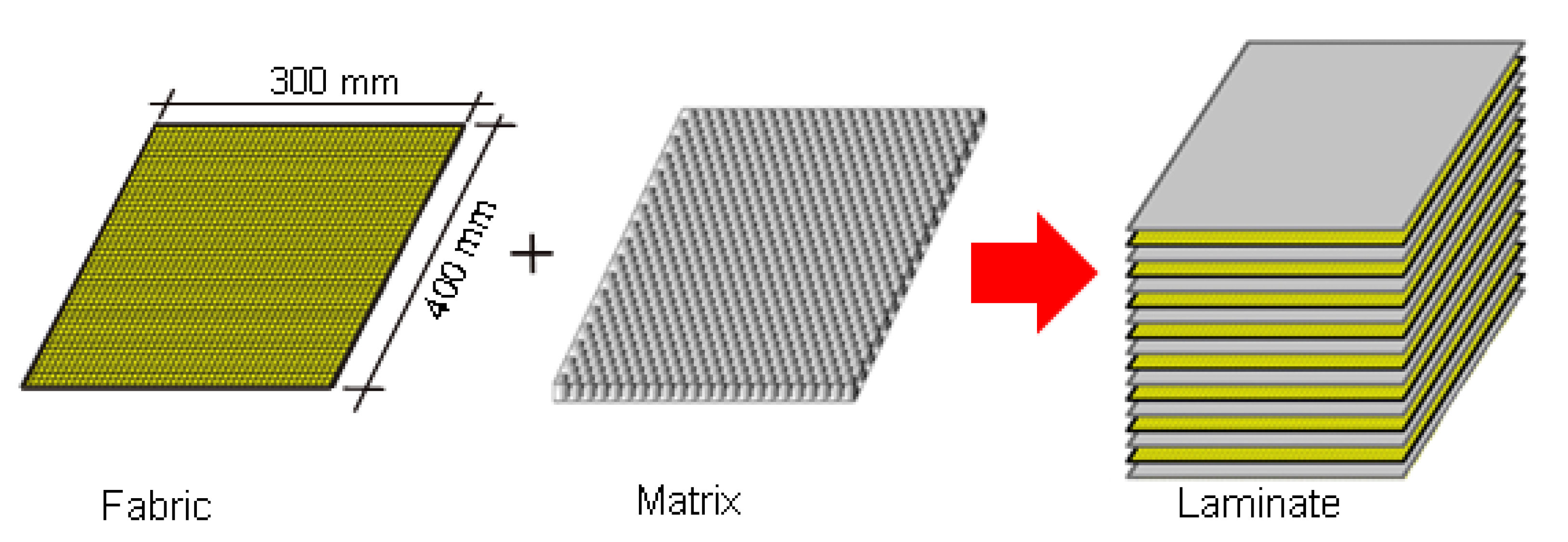
The material responsible for the ballistic properties of the shield was a composite laminate reinforced with aramid fibers with a thickness of 5 mm. The raw material is a long polyamide chain with a minimum of 85% amide groups (NHCO). This laminate was produced by the Polish company MIKANIT, with the trade name LIM 1, and was created from eight layers of Twaron T750 aramid fabric, combined with a polymer warp Neoprene WRT [14] (Figure 3) under appropriate pressing pressure.

Figure 3.
Composite laminate structure.
Studies of traditional strength properties of shields consist of determining material constants, usually obtained from the static tensile test, and stretching a properly prepared sample in the axial direction until the sample breaks. The test allows us to observe how the material behaves in the entire range of deformations, i.e., from elastic and elastic-plastic to breakage. Based on the test results, both strength and plastic parameters of the stretched material were determined.
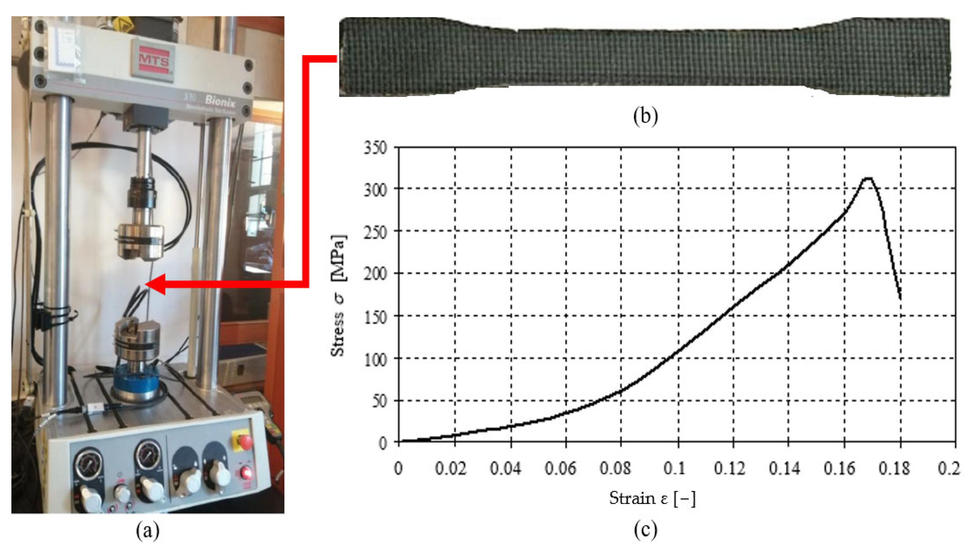
In the study, we used the ballistic laminate LIM 1, produced by the domestic manufacturer. Tests of the strength characteristics for the laminate were performed on the MTS Bionix testing machine (MTS Systems, Berlin, Germany) with a constant displacement increase of 0.05 mm/s.
Laminate samples were cut into the shape of oars with a water jet to obtain the most accurate shape (other cutting techniques caused the fibers to be pulled out), according to ASTM D638-99 pr. Type 1. [15].
The tensile strength test results for LIM 1 are presented in Figure 4. These are averaged results from several trials. From the structure of the curve σ − ε, it can be observed that the laminate stress slowly increases as a function of deformation occurs in the initial tensile phase. Due to the nature of the weave, the load is mainly taken over by the polymer matrix. In the further part of the graph, a rapid increase in the deformation curve is noticeable, which results in an increase in the role of fabric fibers up to plastic deformation and, as a result, to the breaking.

Figure 4.
Stand for strength tests: (a) strength machine MTS, (b) specimen, (c) specimen after breaking, (d) selected stretching curve for LIM 1 laminate specimen.
In addition, tests related to the influence of damping force on the results during stretching of the analyzed samples were carried out. The tests were carried out for two tensile velocity, i.e., a minimum 0.05 mm/s and maximum 90 mm/s. The results are illustrated in the Figure 5.
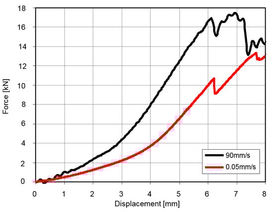
Figure 5.
Selected results of LIM 1 laminate stretching for two extreme stretching velocities.
Based on data from the static tensile test, the mean Young’s modulus and other parameters for the tested composite were determined. The results are summarized in Table 1.

Table 1.
Characteristics of the LIM 1 laminate and its components.
2.1.2. Magnetic Foil
One of the components of the energy-absorbing composite shield was a magnetic foil from Media Mag. Its main purpose was to quickly attach the shield to the bodywork. This foil has an appropriate magnetic attraction force and, according to the manufacturer’s information, is called a flexible magnet. Additionally, the fact that its geometry adapts to the shape of the car body may also have a positive impact on increasing the ballistic protection of the protected space. An example is PVB interlayer foil (polyvinyl butyral), which is used in bulletproof glass technology. In this case, the foil is expected to have a positive effect, as if a rubber layer had been applied.
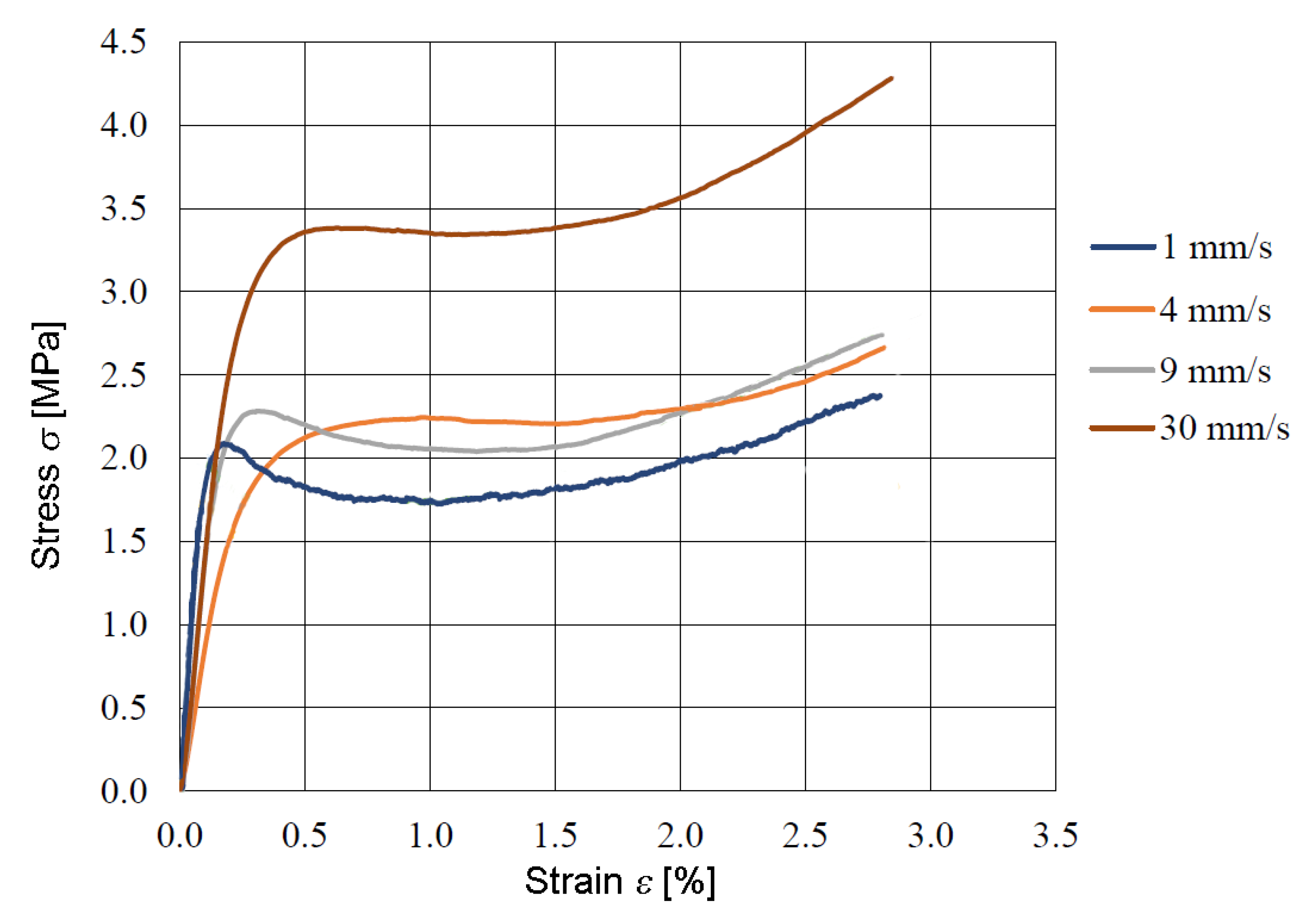
The strength tests conducted were aimed at checking the strength parameters and developing material constants for the constitutive model describing the behavior of this type of material. Strength tests were performed on a testing machine (see Figure 4a) with different strain rates. Example results are presented in Figure 6.
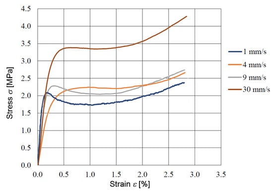
Figure 6.
Results of magnetic foil stretching for different velocities.
The tensile curves show that the material exhibits hyperelastic properties. These types of materials are characterized by the ability to undergo large elastic deformations under the influence of tensile forces while retaining their original properties. Hyperelastic materials exhibit various properties; therefore, models of hyperelastic materials are used to classify them. These are constitutive models, ideally for elastic materials, which are used, among others, in numerical modeling. In this case, the Ogden model was used to describe the tested material. The Ogden model is described by the following mathematical equation:
where are material constants and 𝜆i is principal stretches.
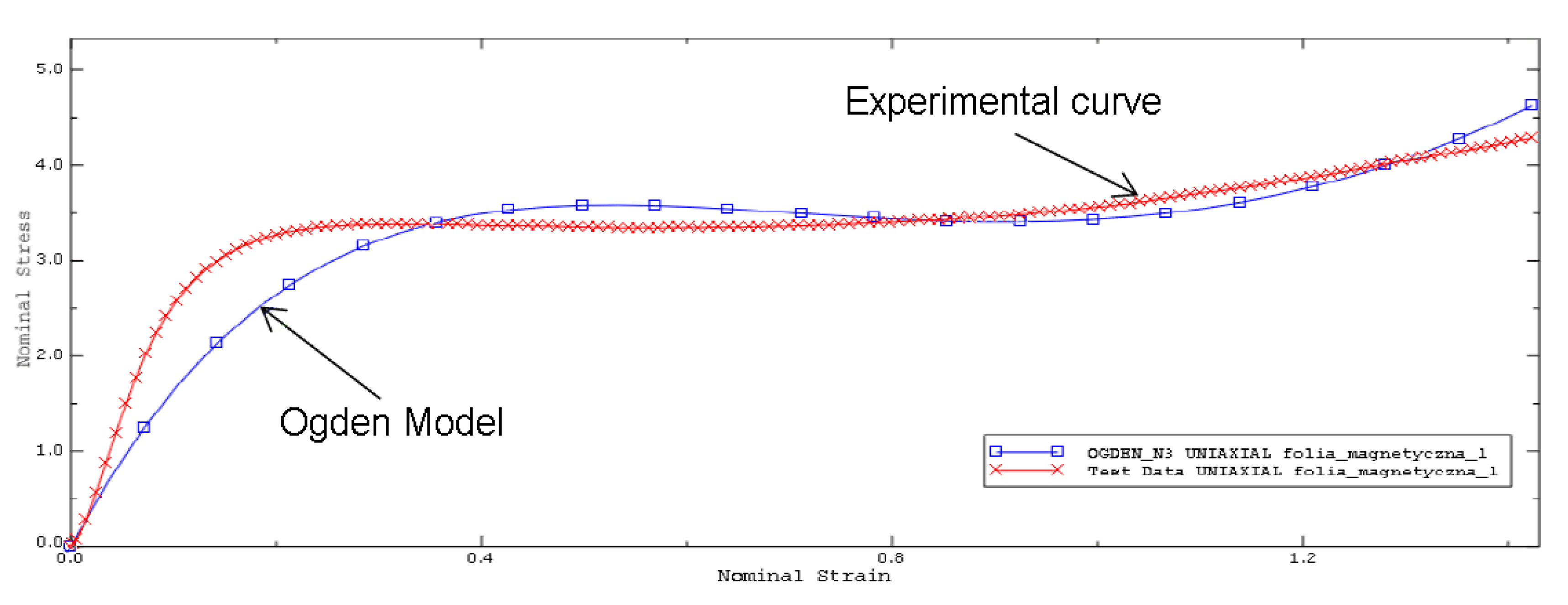
To determine the material constants of the Ogden model, ABAQUS software was used using the “Evaluate” function. On the basis of the curve from the test with the highest tensile velocity (30 mm/s), due to the closest approximation to the working conditions of the material related to the impact on ballistic impact characterized by very high velocity, it was compared with the obtained curve of the Ogden model (see Figure 7). In this way, the material constants of the model were determined, and the data are summarized in Table 2.
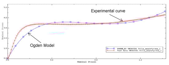
Figure 7.
Comparison of the experimental and Ogden model results.
Table 2.
Ogden model parameters.
The scaling of the constitutive characteristics of the material model used for the magnetic foil was used for further FEM analyses.
2.2. Gun Fire and Car Body Material Characteristics
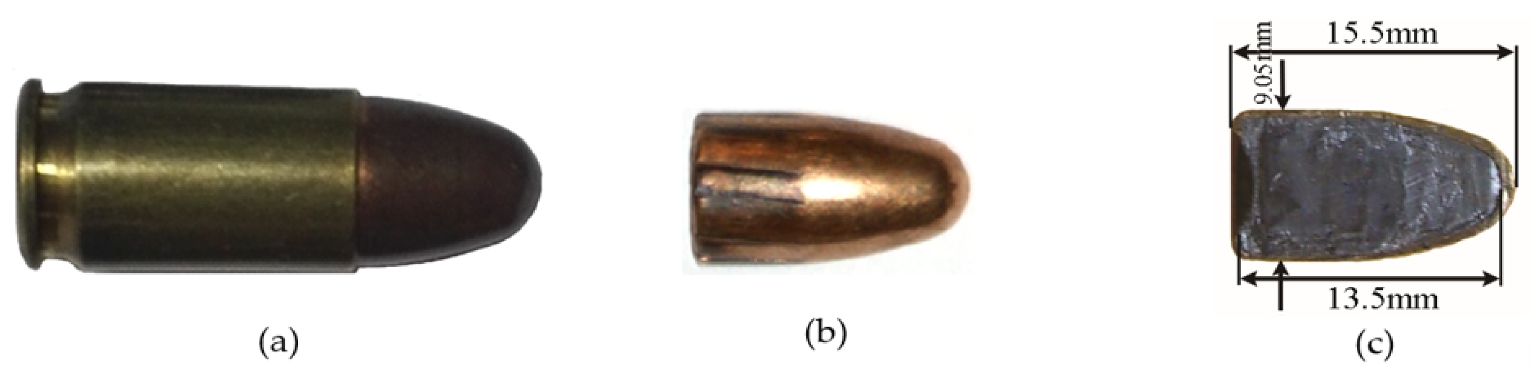
The 9 × 19 mm FMJ Parabellum pistol cartridge, which meets NATO standards, was used in the tests. Its basic parameters are listed in Table 3, and the construction is illustrated in Figure 8.
Table 3.
Characteristic 9 × 19 mm FMJ Parabellum round.
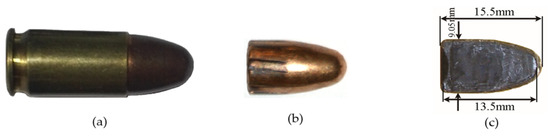
Figure 8.
General view of the ammunition: (a) 9 × 19 mm FMJ Parabellum, (b) bullet, (c) bullet cross section.
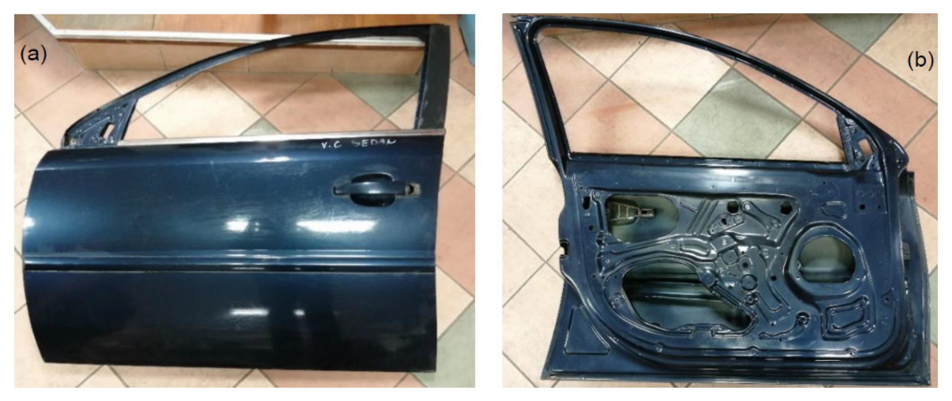
An element of the examined structure of the body plating of a passenger vehicle was the front doors from any selected car (Figure 9). The strength parameters of the car body plate have been adapted from the literature. For the exterior of cars, soft steels with a yield strength of less than 300 MPa and a carbon content not exceeding 0.3% [16] are used.
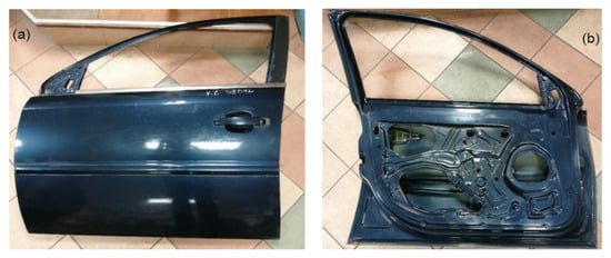
Figure 9.
General view of the door from the Ford Focus car: (a) from the front, (b) from the inside.
2.3. Laboratory Tests
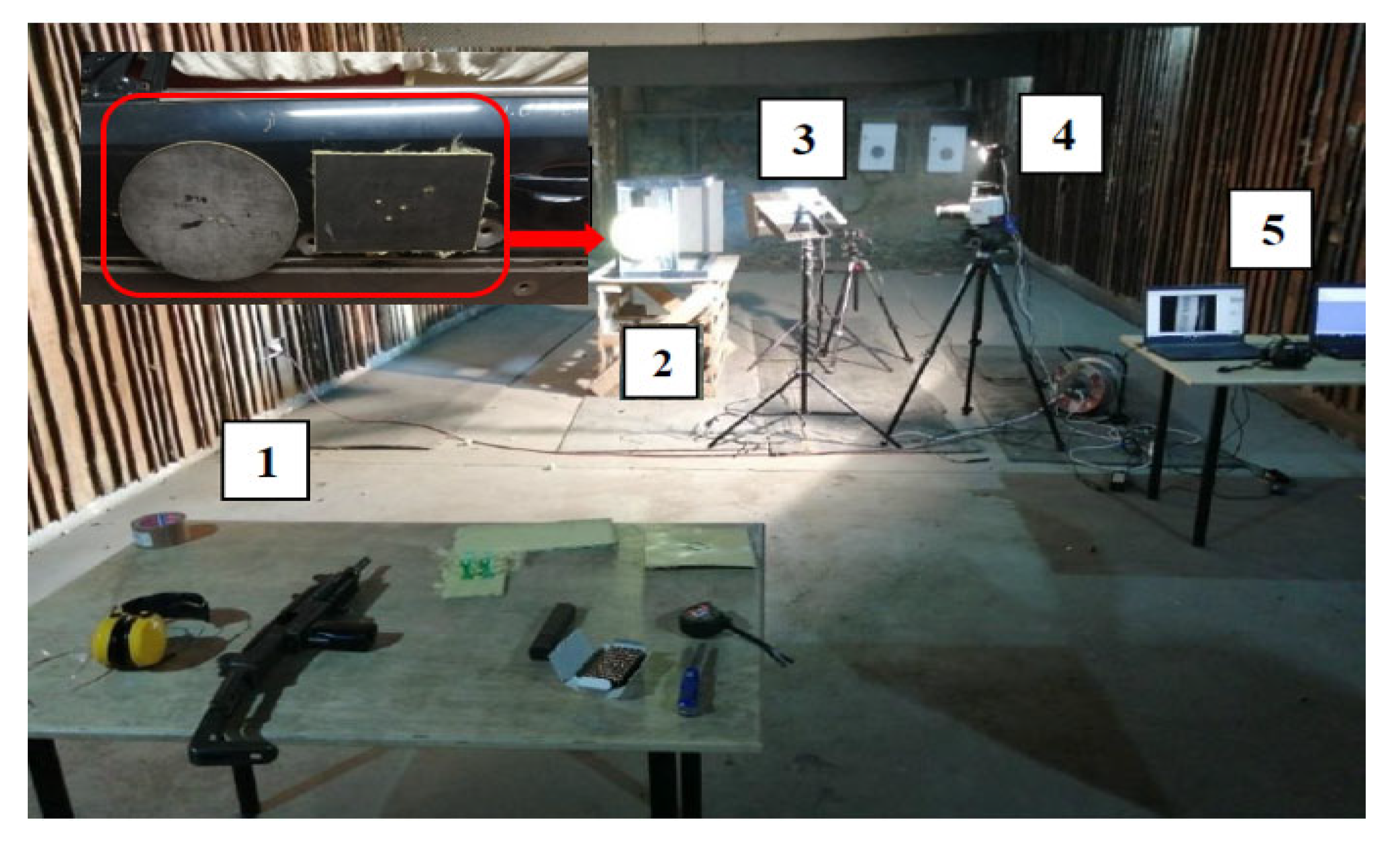
Laboratory tests included shooting at the shield mounted on the door, considering the guidelines of the standard [13]. The moment of impact of the projectile was recorded using a high-speed camera. The test was carried out by attaching the composite to the door, first with magnetic foil and then with adhesive tape. The door with the shield was placed on a wooden platform with the front part facing towards the shooting position. Each attempt was repeated three times. The test methodology is shown in Figure 10.
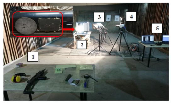
Figure 10.
General view of the tests: (1) fired from the position, (2) samples position, (3) light lamp, (4) place for data camera recorded, (5) computer system.
The samples mounted on the body doors were fired from the position (1) from an UZI submachine gun 5 m away from the place of attachment of samples (2). Each shot was recorded using a Phantom VEO 710 (4) high-speed camera (Vision Research, New Jersey, USA) at 42,000 frames per second. In addition to this, the firing site was illuminated with special LED lamps (3). The registration process took place directly on a PC, using special software to operate the camera on the computer (5). Examples of results from field tests are presented below (Figure 11).
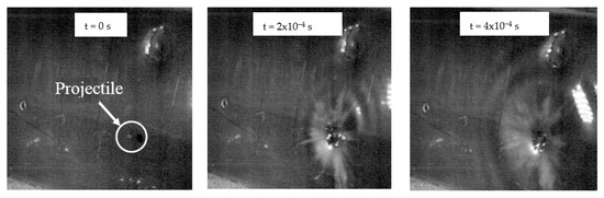
Figure 11.
Sample results recorded with a high-speed camera.
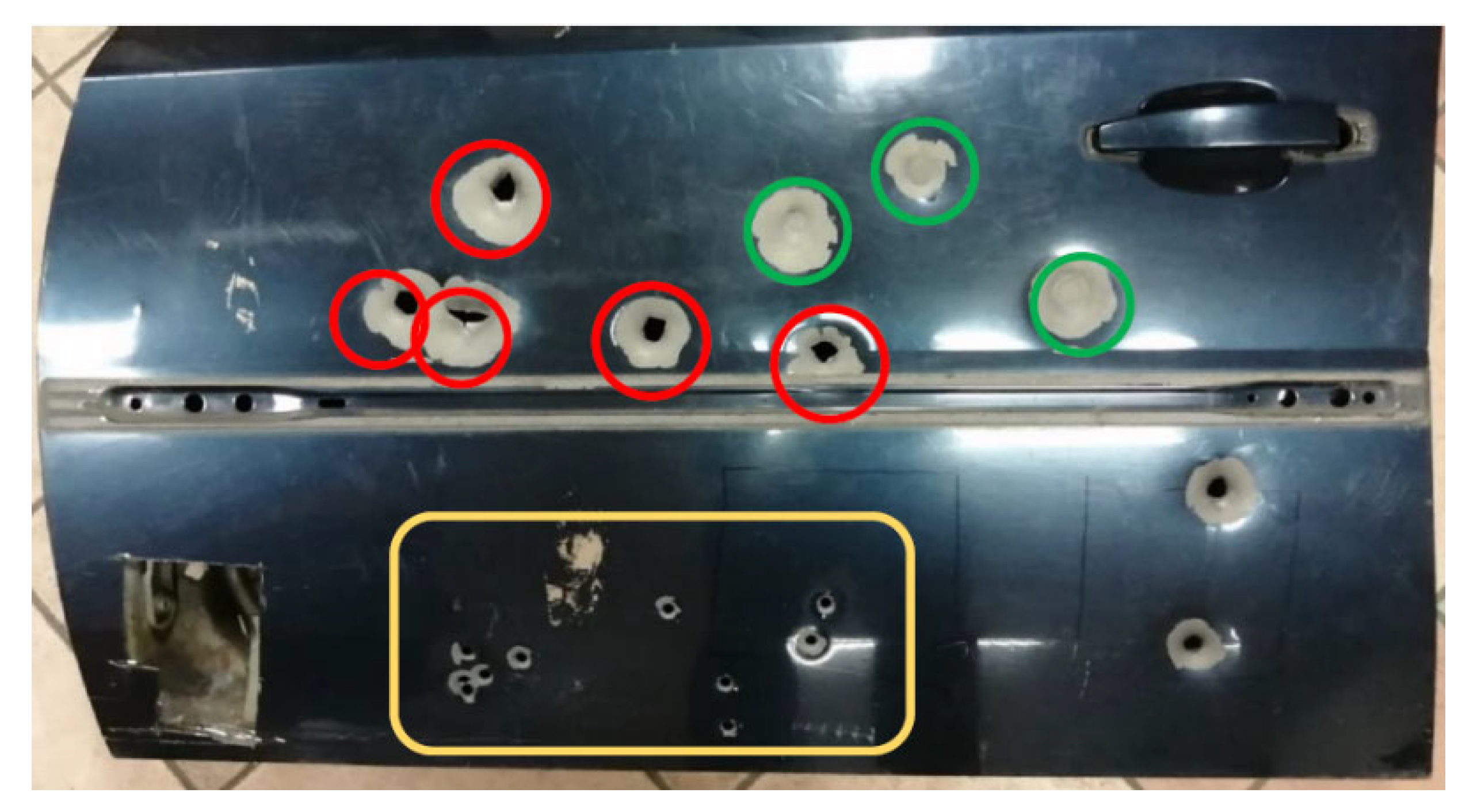
The research showed the influence of the way the shield is fixed on its ballistic properties. The shield mounted on the door with adhesive tape fulfilled its function by stopping the projectile, while the shield attached with magnetic foil let the projectile through (Figure 12). Images from the high-speed camera show that greater deflection occurred with the shield mounted with adhesive tape than with the magnetic foil solution. Hence, it can be concluded that the introduction of additional stiffening of the composite by gluing the magnetic foil on the entire surface of the shield reduced the deflection range of the composite, which in turn had a negative impact on the ballistic properties of the shield (total penetration).

Figure 12.
Door after shooting: bullet hole marked with red circles, deflection zones marked with green circles and the yellow marked zone represents the area not covered by the shields.
In Figure 12, the bullet hole is represented with red marks (magnetic fastening), while green marks show the deflection zones (tape fastening) and yellow represents the area not covered by the shields.
2.4. Numerical Analysis
The last stage of this work was the numerical analysis of the phenomenon of the projectile hitting the designed shield. Due to the very short duration, very high velocities and nonlinear characteristics of the processes occurring during a ballistic impact, this phenomenon should undoubtedly be classified as dynamic. The most used method to describe the phenomenon is the finite element method, which is also used to solve this type of problem by computer simulation [17,18]. FEA analysis was conducted in the ABAQUS/Explicit environment. Given that the composite consists of eight layers of fabrics, holistic modelling was used. Based on this work [19,20,21,22], a model was adopted in which the structure of the shield was simplified, its dimensions were reduced and the conditions of the modeled phenomenon were simplified, for which factors such as temperature, air resistance or rotation of the projectile were not considered.
Based on the assumed values, as material data for numerical analysis, the parameters of the Johnson-Cook (J-C) model were determined according to the Equation (2) [21]. The adopted parameters of the constitutive model (1) are summarized in Table 4.
where ε is the plastic strain, is the plastic strain rate, is the reference strain rate, A is the yield stress of the material under reference conditions, B is the strain hardening constant, n is the strain hardening coefficient and C is the strengthening coefficient of strain rate.
Table 4.
Material data assumed in the J-C model [23].
It should be noted that the dynamic characteristics of LIM 1 laminate were estimated as follows, namely that the quasi-static velocities adopted in the tests were in the range from 0.05 mm/s to 90 mm/s in order to illustrate the strain rate-induced strengthening. Then the J-C model was used, especially its second element , taking into account the strain rate. In the preliminary numerical simulations, the parameters A, B and n were changed depending on the parameter ε.
The analysis assumed an initial velocity of 400 m/s for the Parebellum projectile as input parameters related to the FB2 level of the standard.
At the first step, the hole of the bullet through the car door sheet was analyzed to verify the correctness of the adopted parameters and numerical model. The second analysis involved the collision of the projectile with the ballistic shield, and the third analysis modeled the collision of the projectile with the shield mounted on the door.
As the object of numerical analysis, a model of sheet metal, magnetic foil and a shield with dimensions of 100 × 100 mm was adopted where the model was scaled in Section 2.1.2. The adopted thicknesses that corresponded to the actual data were 1 mm for the car body sheet, 2 mm for the magnetic foil and 5 mm for the composite. Discrete models were made separately for the jacket and separately for the core. Due to the better fit to the geometry, 10-node Tetra elements with a size of 0.5 mm were adopted for the discretization of each of them. A two-stage homogenization of the ballistic laminate was used. The first stage consisted of fiber layer–matrix homogenization. In the second stage homogenization was performed using the representative volume element (RVE) [24]. For discretization of steel plate and composite models, Hex elements with an element size of 0.5 mm were assumed. Contact and friction between individual elements were modeled based on [25]. The discrete models obtained in this way are shown in Figure 13.
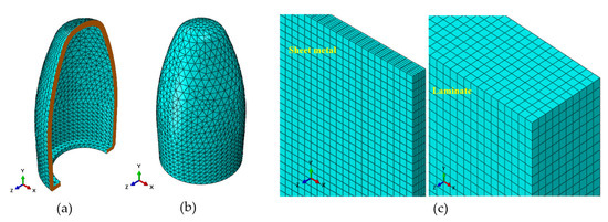
Figure 13.
Discrete models: (a) bullet jacket, (b) bullet core, (c) car door sheets and ballistic laminate.
The restraint of the shield was blocked at translations and rotations in three axes X, Y and Z. When the elongation exceeded 2%, the shield was destroyed. The destruction in the J-C model is associated with the accumulation of plastic deformation. It is assumed that it starts when the state variable Wd reaches the value 1. The parameter Wd is defined by the equation:
where is the incremental strain and is the equivalent failure strain.
The parameter is described by the following equation:
where d1, d2, d3, d4 and d5 are material parameters, σ* is a dimensionless ratio expressed as the pressure P and σ is the effective stress (von Mises equivalent stress), is the strain rate corresponding to a car body sheet metal, is the reference strain and T* is the homologous temperature (dimensionless temperature value). Between the homologous temperature (T*) and melt temperature (Tm), the following relationship exists:
The parameter is determined by the components of the plastic deformation rate expressed by the relationship:
where is the initial equivalent plastic strain, t is time and are components of the plastic strain speed.
In the analyzed case, the damage in the J-C model was described by a progressive model according to the material, which was car body sheet metal. It should be emphasized that the parameters used to identify damage initiation are the result of the authors’ previous work and taken from the literature [19,22,23,25]. The data are summarized in Table 5.
Table 5.
Material data assumed in damage to the J-C model.
3. Results and Discussion
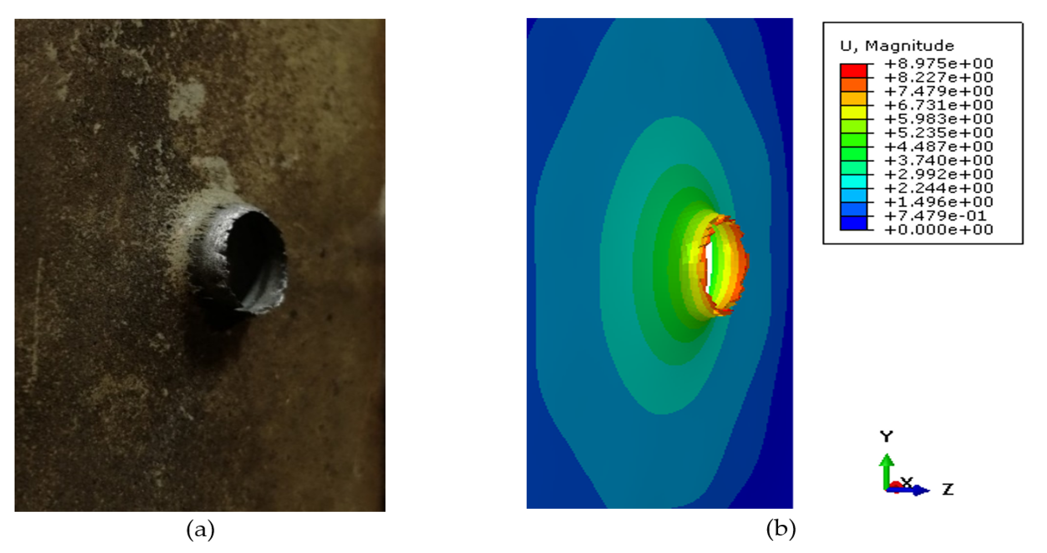
The object of the first analysis was the impact of projectile on the bare plate of car doors. The simulation results illustrating the deflection in millimeters, in combination with the effect of the bullet penetrating the front sheet of the door, are presented in Figure 14.
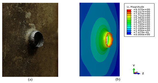
Figure 14.
Bullet penetrating the door: (a) experimental, (b) numerical simulation.
Using a caliper, the actual deflection of the sheet was measured to be 7.42 mm. Based on the adopted fitting scale, it was considered that the obtained simulation result reflects the penetration obtained by the experimental method (δ = 17.3%) to an acceptable extent. Therefore, it was assumed that the applied methodology of scaling the models is correct, and one can proceed to scaling the deformation of the projectile.
In the next cork, the collision of the projectile with a composite ballistic laminate was examined. In this way, a specific verification of the mushrooming of the projectile on the LIM 1 laminate was carried out. The results of these studies (Figure 15) confirm the proper correlation between experimental and numerical simulation.

Figure 15.
Comparison of numerical and experimental deformation modes: (a) numerical simulation, (b) deformation of laminate plate, (c) experimental bullet deformation, (d) experimental bullets deformation.
Due to the adopted method of modeling, that being the composite in the form of a rectangular plate instead of the form of alternating layers of fibers and laminate, the results are approximate. As a result of comparing the deformation of the numerical composite with the real one, a difference of δ = 7.2% was obtained, which is a result that coincides very well with the experiment. On this basis, it was confirmed that the adopted methodology of numerical calculations and the adopted parameters are appropriate, and the deflection course of the ballistic laminate can be considered as the basis for further analysis.
The last part of the numerical analysis is the simulation of the impact of the projectile on the full ballistic package mounted on the door. The geometrical model of the considered system is shown in Figure 16.
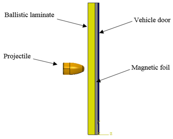
Figure 16.
Scheme adopted for numerical analyses of the protective system of the vehicle door surface.
Numerical analyses were performed using FEM of the above material system. The simulation illustrates the overall deformation of the ballistic shield with support, which is intended to be mounted externally on the vehicle, based on individual time steps. As can be seen in Figure 17, the course of this deformation reaches a maximum dynamic deflection of about 30 mm.
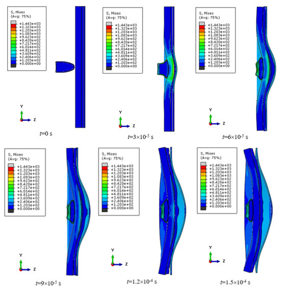
Figure 17.
The simulation of a projectile’s impact on a ballistic package.
The results obtained from numerical simulations correlate with the results of other researchers [26,27]. Here it can be clearly seen that in the first phase, the projectile digs into the elements of the shield and the first layers of laminate fabrics are cut. However, the resistance force of the material causes the projectile to slow down, and the frontal surface of the projectile takes the shape of a mushroom because of the primary fibers. Additionally, the primary fibers are stretched until the strength limit is exceeded, which then breaks off. The continuous build-up of the projectile frontal surface causes the local impact energy dissipation zone to increase, triggering the activity of the secondary fibers [28,29,30]. From the opposite side, the deformation of the shield increases, and due to the support of the car body sheet, the individual layers of the fabric are compressed and stretched at the same time, due to the formation of a post-impact cone. This process continues until the projectile loses velocity. The permanent deformation was 12 mm for attaching the shield to the adhesive tape. The shield attached to the magnetic tape is perforated, as shown in Figure 12. The secondary fibbers during shock load are associated with the delamination of the warp and fabric layers.
The process of impact load of the ballistic shield mounted on the selected element of the car body proceeded as intended on the FB2 deck only for fixing on adhesive tape, while the installation on magnetic tape did not meet the expectations of the researchers. As shown, the dynamic deformation in the numerical simulation for attaching the shield to the adhesive tape eventually reached the range of approximately 35 mm (Figure 18a), which is an acceptable result.
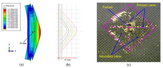
Figure 18.
Numerical and experimental deformation analysis view: (a) numerical simulation of the deformation of the shield mounted on the tape; (b) estimated dynamic deformation from FEM; (c) one of the selected ballistic laminate layers.
The presented results (Figure 18) with the use of FEM allow us to assess the behavior of individual elements of the ballistic package. The deformation (Figure 18a,b) for the selected system correlates with the results of other researchers [31,32], which also translates into the assessment of damage to the surface layers of the material system (Figure 18c). As shown, the projectile perforated through seven layers, while the last layer stopped the projectile, where its mushroomed surface was braked on the primary fibers. To sum up, the obtained results from FEM were optimally validated by means of a ballistic experiment, as evidenced by the obtained traces on the car body doors (Figure 12) marked in green circles.
4. Conclusions
The proposed technique of the development of the crack impact of the steel sheet of the car door mirrors determine an acceptable experimental result (δ ≤ 10%). Numerical analysis of the case of collision of the bullet with the laminate itself showed a greater deflection of the composite than in the case of a system with support on the elements of the car body. The results reveal that the mounting of the ballistic system significantly affects the results, which has been repeatedly emphasized in earlier works [33]. The obtained results of permanent deformation of the analyzed ballistic system in FEM showed only an error in the range of 7.2%, compared to the actual results. The small error proves the correctness of the adopted research methodology and the appropriate iteration of numerical models to assess their sensitivity to perforation of the car body sheet, deformation of the LIM1 laminate and scaling of the projectile deformation. Furthermore, the results highlight that the magnetic tape used intensified the perforation of the ballistic system. This phenomenon requires further research, with particular emphasis on fastening. The proposed solution seems promising and can be used as an alternative to quickly strengthen the steering compartment of the vehicle, which can be used in humanitarian operations.
Author Contributions
Conceptualization, M.M. and K.J.; methodology, M.M.; software, D.P.; validation, A.K., M.B. and K.J.; formal analysis, N.B.; investigation, M.M.; data curation, D.P.; writing—original draft preparation, M.M.; writing—review and editing, A.K. and M.B.; visualization, N.B.; supervision, K.J. All authors have read and agreed to the published version of the manuscript.
Funding
This research received no external funding.
Data Availability Statement
The authors declare that data has not been inappropriately enhanced.
Acknowledgments
Calculations were carried out at the Wroclaw Centre for Networking and Supercomputing (http://www.wcss.pl), grant No. 452.
Conflicts of Interest
The authors declare no conflicts of interest.
References
- Lott, J.R. Comparing the Global Rate of Mass Public Shootings to the U.S.’s Rate and Comparing Their Changes over Time, Rochester, New York, 2018. Available online: https://ssrn.com/abstract=3289010 (accessed on 10 February 2023).
- Gzik, M.; Wolański, W.; Gzik-Zroska, B.; Joszko, K.; Burkacki, M.; Suchoń, S. Analysis of various factors impact on safety of armored vehicle crew during an IED explosion, Recent Developments and Achievements in Biocybernetics and Biomedical Engineering. In Proceedings of the 20th Polish Conference on Biocybernetics and Biomedical Engineering, Kraków, Poland, 20–22 September 2017. [Google Scholar]
- Branco, G.C.P.; Basile, E.G.; Morrone, R.G.; Cardoso, A.V.D.; Folgar, F.; Coelho, A.S. Ballistic armoring of passenger cars on the assembly line adds quality and passengers comfort by using advanced and light weight composite materials. SAE Tech. Pap. 2004, 113, 650–659. [Google Scholar]
- Siengchin, S. A review on lightweight materials for defence applications: Present and future developments. Def. Technol. 2023, 24, 1–17. [Google Scholar] [CrossRef]
- Pach, J.; Kuterek, E. Investigation of the quasi-static penetration resistance behaviour of carbon/aramid fibre-reinforced PP laminate. Materials 2021, 14, 709. [Google Scholar] [CrossRef]
- Abtew, M.A.; Boussu, F.; Bruniaux, P.; Loghin, C.; Cristian, I. Ballistic impact mechanisms—A review on textiles and fibre-reinforced composites impact responses. Compos. Struct. 2019, 223, 110966. [Google Scholar] [CrossRef]
- Ballistic Door Panels. Available online: https://www.pro-gard.com/product/ballistic-door-panels/ (accessed on 10 December 2022).
- Scanfiber Composites Enhanced Spall-Liner. Available online: https://scanfiber.dk/applikationer/beskyttelse-til-lands/enhanced-spall-liner.aspx (accessed on 12 December 2022).
- Mamys, M. Design of an Energy-Intensive Shield for the Inner Part of the Front Car Door in Terms of Penetrator—Shield. Ph.D. Thesis, Wroclaw University of Technology, Wrocław, Poland, 2023. [Google Scholar]
- Pratomo, A.N.; Santosa, S.P.; Gunawan, L.; Putra, I.S. Countermeasures design and analysis for occupant survivability of an armored vehicle subjected to blast load. J. Mech. Sci. Technol. 2020, 34, 1893–1899. [Google Scholar] [CrossRef]
- Hazell, P. Armour: Materials, Theory, and Design; Taylor & Francis Group: New York, NY, USA, 2016. [Google Scholar]
- Ojoc, G.G.; Pirvu, C.; Sandu, S.; Deleanu, L. Standardization in testing ballistic protection systems. IOP Conf. Ser. Mater. Sci. Eng. 2020, 724, 012049. [Google Scholar] [CrossRef]
- CEN-EN 1522:2000; Windows, Doors, Shutters and Blinds—Bullet Resistance—Requirements and Classification. European Committee for Standardization: Brussels, Belgium, 2000.
- DuPontTM Neoprene WRT. Product Sales Specifications. Available online: https://www.vanderbiltchemicals.com/specs/76447.pdf (accessed on 10 December 2022).
- ASTM D638-99; Standard Test Method for Tensile Properties of Plastics. ASTM International: West Conshohocken, PA, USA, 2002.
- Car Body Building Types History and Used Materials. Available online: https://autokult.pl/budowa-nadwozi-samochodowych-typy-historia-i-stosowane-materialy-cz-2,6809104216987265a (accessed on 12 December 2022).
- Kędzierski, P.; Watorowska, J. Application of meshless methods for pistol bullets modelling. Biul. WAT. 2021, 70, 89–99. [Google Scholar]
- Marechal, C.; Bresson, F.; Haugou, G. Numerical tools for the impact parameters identification of the 9 mm Parabellum FMJ Bullet. Engng. Trans. 2011, 59, 263–272. [Google Scholar]
- Zochowski, P.; Bajkowski, M.; Grygoruk, R.; Burian, W.; Pyka, D.; Jamroziak, K.; Bocian, M. Ballistic impact resistance of bulletproof vest Inserts containing printed titanium structures. Metals 2021, 11, 225. [Google Scholar] [CrossRef]
- Pyka, D.; Pach, J.; Bocian, M.; Jamroziak, K. Qualitative evaluation of modeling the aramid fabric elementary cell in the piercing process with a 9 mm full metal jacket projectile. In Proceedings of the 14th International Scientific Conference Computer Aided Engineering; Springer: Berlin/Heidelberg, Germany, 2019; pp. 581–590. [Google Scholar]
- Mackiewicz, A.; Pyka, D.; Pach, J.; Jamroziak, K.; Bocian, M. Comparison of numerical modelling methods of innovative materials for ballistic shields. In Advanced Materials for Defense: Development, Analysis and Applications; Springer Proceedings in Materials; Springer: Berlin/Heidelberg, Germany, 2020; Volume 4, pp. 119–127. [Google Scholar]
- Soydan, A.M.; Tunaboylu, B.; Elsabagh, A.G.; Sarı, A.K.; Akdeniz, R. Simulation and experimental tests of ballistic impact on composite laminate armor. Adv. Mater. Sci. Eng. 2018, 2018, 4696143. [Google Scholar] [CrossRef]
- Zochowski, P.; Bajkowski, M.; Grygoruk, R.; Burian, W.; Pyka, D.; Jamroziak, K.; Bocian, M. Finite element modeling of ballistic inserts containing aramid fabrics under projectile impact conditions—Comparison of methods. Compos. Struct. 2022, 294, 115752. [Google Scholar] [CrossRef]
- Siddharth, S.; Ramesh, A. Homogenization of mechanical properties of unidirectional fibre reinforced composites with matrix and interface defects: A Finite Element Approach. J. Phys. Conf. Ser. 2019, 1355, 012040. [Google Scholar] [CrossRef]
- Goroch, O.; Gulbinowicz, Z.; Magier, M.; Bednarczyk, E.; Skoczylas, P.; Pankowski, Z.; Sweklej, P.; Zochowski, P.; Jedrzejewski, W. Development and experimental verification of the new WHA sinters intended for kinetic energy projectiles. Contin. Mech. Therm. 2023, 35, 2193–2205. [Google Scholar] [CrossRef]
- Sławski, S.; Szymiczek, M.; Kaczmarczyk, J.; Domin, J.; Duda, S. Experimental and numerical investigation of striker shape influence on the destruction image in multilayered composite after low velocity impact. App. Sci. 2020, 10, 288. [Google Scholar] [CrossRef]
- Asemani, S.S.; Liaghat, G.; Ahmadi, H.; Anani, Y.; Khodadadi, A.; Charandabi, S.C. The experimental and numerical analysis of the ballistic performance of elastomer matrix Kevlar composites. Polym. Test. 2021, 102, 107311. [Google Scholar] [CrossRef]
- Pandya, K.; Kumar, C.; Nair, N.; Patil, P.; Naik, N. Analytical and experimental studies on ballistic impact behavior of 2D woven fabric composites. Int. J. Damage Mech. 2015, 24, 471–511. [Google Scholar] [CrossRef]
- Oliveira Braga, F.; Lima, E., Jr.; Sousa Lima, E.; Monteiro, S. The effect of thickness on aramid fabric laminates subjected to 7.62 mm ammunition ballistic impac. Mater. Res. 2017, 20, 676–680. [Google Scholar] [CrossRef]
- Li, J.; Huang, C.; Ma, T.; Huang, X.; Li, W.; Liu, M. Numerical investigation of composite laminate subjected to combined loadings with blast and fragments. Compos. Struct. 2019, 214, 335–347. [Google Scholar] [CrossRef]
- Ingle, S.; Yerramalli, C.S.; Guha, A.; Mishra, S. Effect of material properties on ballistic energy absorption of woven fabrics subjected to different levels of inter-yarn friction. Compos. Struct. 2021, 266, 11382. [Google Scholar] [CrossRef]
- Yang, Y.; Chen, X. Influence of fabric architecture on energy absorption efficiency of soft armour panel under ballistic impact. Compos. Struct. 2019, 224, 111015. [Google Scholar] [CrossRef]
- Jamroziak, K.; Bocian, M.; Kulisiewicz, M. Effect of the attachment of the ballistic shields on modelling the piercing process. Mechanika 2013, 19, 549–553. [Google Scholar] [CrossRef]


Disclaimer/Publisher’s Note: The statements, opinions and data contained in all publications are solely those of the individual author(s) and contributor(s) and not of MDPI and/or the editor(s). MDPI and/or the editor(s) disclaim responsibility for any injury to people or property resulting from any ideas, methods, instructions or products referred to in the content. |
© 2024 by the authors. Licensee MDPI, Basel, Switzerland. This article is an open access article distributed under the terms and conditions of the Creative Commons Attribution (CC BY) license (https://creativecommons.org/licenses/by/4.0/).