Article

Vibration Principles Research of Novel Power Electronic Module as Dynamic Vibration Absorber for Chassis-By-Wire

1
R&D Innovation Headquarters, SAIC Motor, Shanghai 201804, China
2
School of Automotives Studies, Tongji University, Shanghai 201804, China
3
Department of Mechanical Systems Engineering, Tokyo University of Agriculture and Technology, Tokyo 184-8588, Japan
*
Author to whom correspondence should be addressed.
Machines 2024, 12(12), 932; https://doi.org/10.3390/machines12120932
Submission received: 18 November 2024 / Revised: 16 December 2024 / Accepted: 17 December 2024 / Published: 19 December 2024

Abstract

This paper presents a novel power electronic module (PEM) for chassis-by-wire in passenger cars. The PEM is supposed to be installed in a close-to-wheel position, which provides electrical interfaces with a power harness and signal harness. When the vehicle is driving, the PEM works as a dynamic vibration absorber (DVA) to diminish the negative effects of un-sprung mass. Based on the vibration system model, the mechanical principles are analyzed and the design parameters are mathematically optimized. For a comparison of different configuration schemes with an in-wheel motor (IWM), we take the condition of a vehicle driving at a speed of 15 m/s on a C-class road to examine indicators of vehicle body acceleration, wheel dynamic load, and suspension dynamic deflection. The calculation results prove that the system has advantages in ride comfort and wheel grounding characteristics. For the detailed design of the machine, we build a digital virtual prototype for simulation. Compared to the initial state, the optimized DVA configuration has obvious suppression in component vibration, including the vehicle body, the IWM, and the PEM. The frequency sweep analysis proves a robust result, which ensures that the frequency and amplitude are both within the vibration tolerance range of PEM operations.

1. Introduction

In recent years, chassis-by-wire technology has developed rapidly. Specifically, drive-by-wire technology with an in-wheel motor (IWM) has the advantages of efficient transmission, an agile response, and independent control of each wheel [1]. However, IWMs suffer from the negative effect of un-sprung mass, which affects the grounding of wheels and leads to a deterioration in ride comfort [2]. Therefore, how to fully leverage the technical advantages of IWMs while suppressing the negative effects of un-sprung mass is a significant research topic.
One of the core components of an electric drive system is the power electronic module (PEM). It is connected to the power battery through a power harness, converting direct current into a three-phase alternating current to meet the working requirements of the motor. At the same time, the PEM is connected to the vehicle control unit (VCU) through a signal harness. When driving, the PEM receives VCU command signals and converts them into MCUs (motor control units) [3]. For an IWM, each wheel corresponds to an individual PEM. The traditional configuration scheme separately installs the PEM on the chassis and arranges electrical connections between the IMW and PEM with three-phase copper bars, high-voltage harnesses, and low-voltage harnesses [4,5]. With the miniaturization of electronic components, both PEMs and IWMs can be integrated and assembled inside the wheel rim. As a result, the system is compact in space and the length of the harnesses is significantly shortened, which improves the reliability of electrical connections [6]. However, this configuration converts the weight of the PEM into un-sprung mass, leading to further deterioration in ride comfort. Therefore, it is necessary to improve ride comfort while the system efficiency and reliability remain at a high level.
The principle of a dynamic vibration absorber (DVA) is to install a spring, damper, and auxiliary mass unit into the main vibration system. By assisting the vibration of the auxiliary mass unit, the force generated by the elastic element on the main vibration system is counteracted, thereby achieving a suppression effect on the main vibration system [7]. Vehicle suspension is typically a two-stage vibration system. The application of the DVA principle can effectively suppress the negative effect of un-sprung mass in vehicle suspension [8]. In this regard, some research has been carried out worldwide, such as the DVA-type wheel motor system developed by Bridgestone [9] and the active wheel scheme proposed by Michelin [10,11]. The University of Stuttgart proposed a DVA concept wheel where the motor moves up and down along the axis of the spring and damper, which is an inspiring case [12]. The author’s research team has also conducted long-term research on DVA, and we believe that the DVA principle is an effective method to deal with un-sprung mass [13]. However, the difficulty lies in how to efficiently utilize the function of the DVA while ensuring the stability of the chassis-by-wire and minimizing additional energy consumption as much as possible. Based on this know-how, the author proposes a solution in the patent [14], which takes the PEM as a DVA mass in a close-to-wheel position. The DVA can diminish shock and vibration on wheel jumping. Differing from the existing DVA schemes mentioned above, this original scheme uses the weight of the PEM as a DVA while the IWM works independently, so the output is expected to be smooth without torque ripple. This avoids any effect on the motor stator or rotor, which eliminates the coupling effect of vertical vibration on longitudinal power output. This paper further studies the vibration principles of this scheme with theoretical modeling, which demonstrates the quantitative impact of each parameter in simulation performance.

2. Research Objective

The research object of this paper is a chassis-by-wire system equipped with an IWM and PEM. The IWM is installed inside the wheel rim, and the suspension arm forms a mechanical connection between the vehicle body and the IWM housing. Figure 1 shows the typical configurations of a drive system on chassis-by-wire. According to the PEM position, there are three types, where (a) shows the traditional type that installs the PEM on the chassis, with the input end of the PEM connected to the power battery through a power harness, while connected to the VCU through the signal harness, and the output end of the PEM connected to the IWM through a power harness and signal harness, respectively, (b) shows the integrated type, where the PEM and IWM are assembled and installed concentrically with the wheel rim, and (c) shows the author’s technical solution, which integrates the PEM on the chassis-by-wire system as a DVA.
Specifically, the technical solution proposed by the author in patent [14] is shown in Figure 2. The technical solution consists of three subsystems, namely the wheel subsystem, the PEM subsystem, and the suspension subsystem. Among them, the IWM adopts an axial-flux-type motor with an outer stator/inner rotor structure, which aims at a higher torque density. The wheel is fixedly connected to the rotor shaft of the IWM, and the motor stator is installed inside the IWM housing. The IWM outside is equipped with threaded holes for installing the upper connection frame, lower connection frame, motor high-voltage three-phase connector, and motor low-voltage signal connector at corresponding positions. The connecting frame is equipped with pin holes, which are connected to the pin shaft of the ball joint. The VCU signal connector of the PEM is electrically connected to the VCU through the signal harness. The battery power connector of the PEM is electrically connected to the power battery through a power harness. The upper connecting frame is equipped with three wire harness holes, which allows the three high-voltage wires to pass through. This makes the spatial position of the wiring harness firm and accurate, ensuring the reliability of the electrical connection in the environment of wheel bumps and vibration impacts.
Figure 3 shows the specific structure of the PEM. Within this, the upper cover of the PEM is installed by tightening the internal hexagonal locking bolt, which achieves the sealing and packaging of the PEM. The interior of the PEM is divided into a high-voltage zone and a low-voltage zone. The PEM is connected to the VCU through a signal harness and VCU signal connector to achieve signal transmission between the IWM and VCU. At the same time, the PEM is connected to the power battery through a power harness and battery power connector to achieve energy transmission between the IWM and the power battery. In the design of the PEM, we select suitable power devices based on specific vehicle requirements and voltage platforms. The core component of the high-voltage area is the inverter, while the core component of the low-voltage area is the MCU. Currently, inverters usually use IGBTs as power semiconductor devices, while SiC inverters are also gradually being promoted. With the rapid development of power electronic technology in recent years, GaN inverters will be promising in the future, with a better performance in operating frequency and conversion efficiency.
In the development of chassis-by-wire technology, there has been a trend in integrating the control of the propulsion domain controller and chassis domain controller [15,16]. The PEM supports the expansion of electrical components to meet potential functional requirements in the future, such as steer-by-wire, brake-by-wire, active suspension system, etc. Power electronics technology is expanding so fast that it can make PEMs lighter and smaller in size in the future, so it is fundamental to study the mechanical rules and vibration principles of the system. From the perspective of a chassis-by-wire system, the performance is affected by the component weight, K&C value, and geometric dimensions, which will be discussed in detail in the following.

3. Research Method

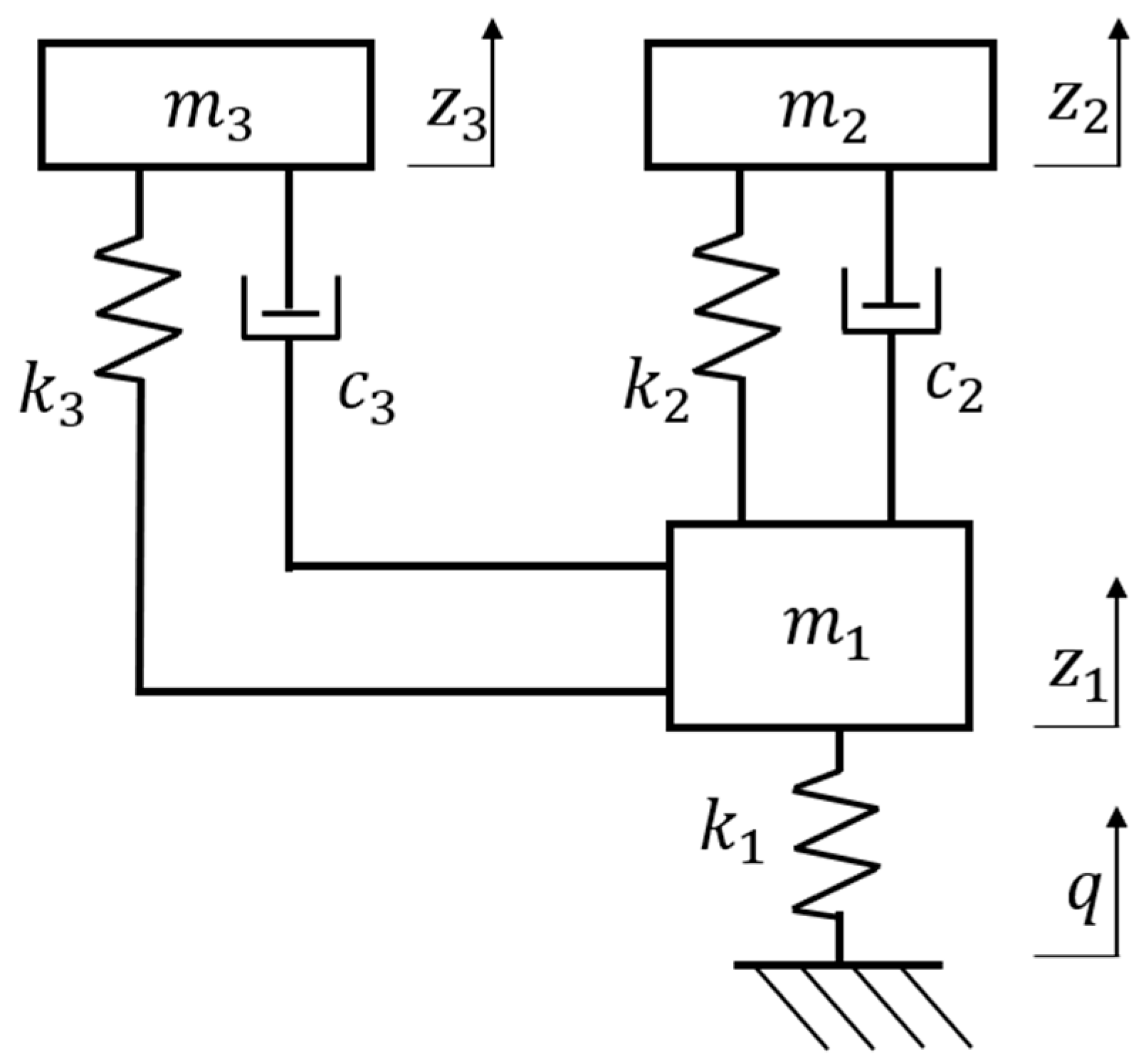
3.1. Dynamic Modeling

The mechanical principle and geometric relationship of the system is shown in Figure 4. The vehicle chassis is hinged and connected to the upper pinhole of the suspension shock absorber assembly in a cylindrical pair through a positioning pin. The lower pinhole of the suspension shock absorber assembly is connected to the lower control arm in a cylindrical pair through a positioning pin. The outer side of the upper control arm is connected to the upper ball joint through a spherical pair. The inner side of the upper control arm is connected to the vehicle body through two cylindrical pairs. The outer side of the lower control arm is connected to the lower ball joint through a spherical pair. The inner side of the lower control arm is connected to the vehicle body through two cylindrical pairs. The top of the PEM damper is connected to the PEM housing through a positioning pin in a cylindrical pair, and the bottom of the PEM damper is connected to the spring seat through a positioning pin in a cylindrical pair. The top of the PEM spring is fixedly connected to the PEM housing, and the bottom of the PEM spring is fixedly connected to the spring seat. The spring seat is embedded in the linear bearing seat and matches the roller and guide rail. The spring can only move in a vertical direction relative to the spring seat.
The instantaneous center point of motion and roll center point of the chassis system are shown in Figure 4. Assuming that all components of the system are rigid bodies, relative sliding and friction losses are ignored. The equilibrium condition of the system is that the sum of the elemental work generated by the virtual displacement   ( W i ) is zero [17], which can be described as follows:
i = 1 n Δ W i = 0 .
Specifically, the DVA is entirely contained within the suspension system, where its spring force is balanced by the internal forces of the system. The micro-element force on the wheels is Δ P and the micro elastic force of the suspension spring is δ P , resulting in micro-deformations Δ f and δ f , respectively, as calculated in Equation (2).
Σ Δ W = Δ P Δ f δ P δ f = 0
By geometric definition, when the wheel rotates along the instantaneous center point of motion, the micro-element angle of δ α results in a vertical displacement Δ f , as follows:
Δ f = l 1 δ α
As the lower arm rotates around point D, the geometric relationship between the displacements δ B of point B and δ E of point E is as follows:
δ E = m n δ B
Since point B is connected to the wheel as a solid body, the geometric relationship at the instantaneous center gives the following:
δ B = l 2 δ α
Solving simultaneously, we obtain the following:
δ f = m l 2 n l 1 Δ f cos θ
This leads to the calculation relationship between the suspension equivalent stiffness and suspension spring stiffness in Equation (7), as follows:
k 2 = k s u s δ f Δ f 2 = k s u s m l 2 n l 1 cos θ 2
Since the DVA can only move vertically due to linear bearing constraints, the DVA equivalent stiffness equals to DVA spring stiffness, as follows:
k 3 = k D V A
Assuming that the mass distribution coefficient of the vehicle is one and the unevenness functions of the left and right road surfaces of the vehicle are the same, the chassis-by-wire with the DVA system can be simplified into a vibration model with three degrees of freedom for 1/4 of the vehicle, as shown in Figure 5. There are three main components with displacement and vibration, namely m1, m2, and m3, with a corresponding degree of freedom, respectively. Among them, m1 represents the un-sprung mass, which consists of the weight of the wheel and the weight of the IWM. m2 represents the sprung mass, which is 1/4 of the vehicle weight. m3 represents the mass of the DVA, which is the PEM weight. k2 represents the equivalent suspension stiffness. c2 represents the equivalent suspension damping coefficient. k3 represents the equivalent DVA stiffness. c3 represents the equivalent DVA damping coefficient. The damping coefficient of the wheel and the harness is ignored.
For the three-degree freedom vibration model [13], the kinetic energy, dissipated energy, and elastic potential energy of the system are expressed in Equations (9), (10) and (11), respectively.
T = 1 2 m 1 z ˙ 1 2 + 1 2 m 2 z ˙ 2 2 + 1 2 m 3 z ˙ 3 2
D = 1 2 c 2 ( z ˙ 2 z ˙ 1 ) 2 + 1 2 c 3 ( z ˙ 3 z ˙ 1 ) 2
U = 1 2 k 1 z 1 2 + 1 2 k 2 ( z 2 z 1 ) 2 + 1 2 k 3 ( z 3 z 1 ) 2
By combining Equations (9)–(11) together, the vibration differential equation of the three-degree freedom model is derived from the Lagrange equation, as shown in Equation (12).
M z ¨ 1 z ¨ 2 z ¨ 3 + C z ˙ 1 z ˙ 2 z ˙ 3 + K z 1 z 2 z 3 = K t q
Specifically,
M = m 1 0 0 0 m 2 0 0 0 m 3
C = c 2 + c 3 c 2 c 3 c 2 c 2 0 c 3 0 c 3
K = k 1 + k 2 + k 3 k 2 k 3 k 2 k 2 0 k 3 0 k 3
K t = k 1 0 0
q is the road surface random excitation, described as follows:
q ˙ ( t ) = 2 π n 00 u q ( t ) + 2 π n 0 G q ( n 0 ) u W ( t )
wherein u is the vehicle speed, taking 15 m/s;
n00 is a lower cut-off frequency, taking 0.011 m−1;
n0 is a reference spatial frequency, taking 0.1 m−1;
G q ( n 0 ) is the road roughness coefficient;
W ( t ) is the filter white noise with a mean value of 0.
We performed the Laplace transform on Equation (12) to obtain the transfer function of the output displacement to road input, as shown in Equation (18).
H = z 1 q z 2 q z 3 q = K t K + C s + M s 2
We performed operations on Equation (18) to obtain the amplitude–frequency function of the vehicle chassis acceleration, relative dynamic load of the wheel, and suspension dynamic deflection on the road speed input, as shown in Equations (19)–(21).
H ( j ω ) z ¨ 2 / q ˙ = z ¨ 2 q ˙ = ω H ( 2,1 )
H ( j ω ) F d / G q ˙ = F d G q ˙ = k 1 m 1 + m 2 + m 3 g 1 ω H ( 1 , 1 ) 1
H ( j ω ) ( z 2 z 1 ) / q ˙ = z 2 z 1 q ˙ = 1 ω H ( 2,1 ) H ( 1 , 1 )
There are three core indicators for evaluating ride comfort, as follows: the RMS (root mean square) of the vehicle body acceleration, the RMS of the wheel dynamic load, and the RMS of the suspension dynamic deflection, respectively [13]. They are calculated with the following Equations (22)–(24).
σ z ¨ 2 = 0 z ¨ 2 q ˙ 2 G q ˙ ( f ) d f 1 2
σ F d = 0 F d q ˙ 2 G q ˙ ( f ) d f 1 2
σ ( z 2 z 1 ) = 0 z 2 z 1 q ˙ 2 G q ˙ ( f ) d f 1 2
A numerical calculation of the RMS indicators above can be achieved based on the equations above. A passenger car chassis-by-wire is taken as an example, with the simulation-related parameters shown in Table 1.
We draw a graph to see the changes in the DVA stiffness and damping impact on the indicators above, as shown in Figure 6, Figure 7 and Figure 8. We can see that the influence of the DVA stiffness on the three indicators is relatively small, while the influence of the DVA damping on all three indicators is relatively large. Moreover, when the DVA damping changes, all three indicators will have a minimum value.

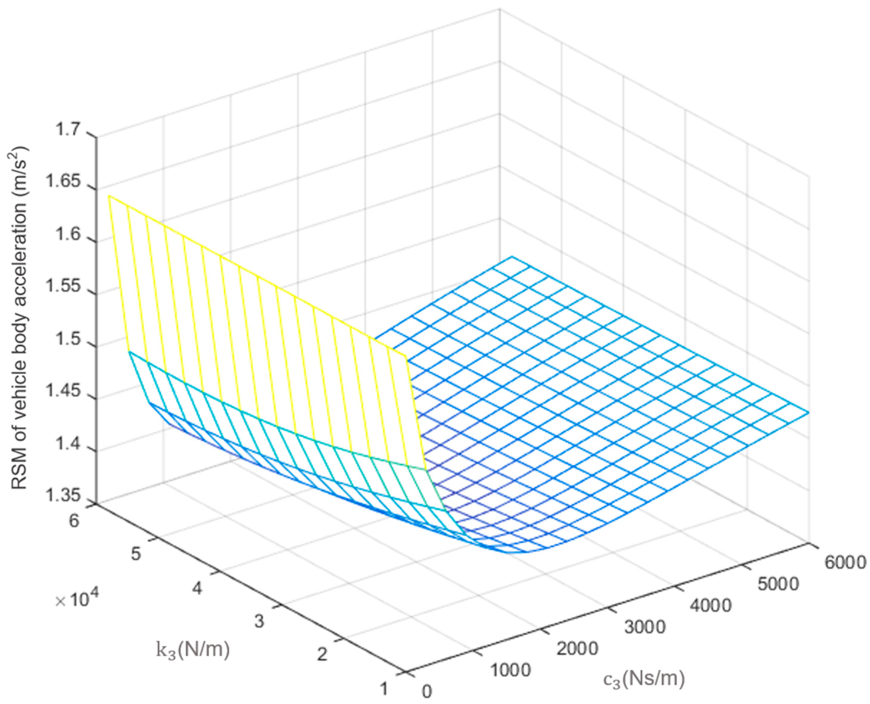
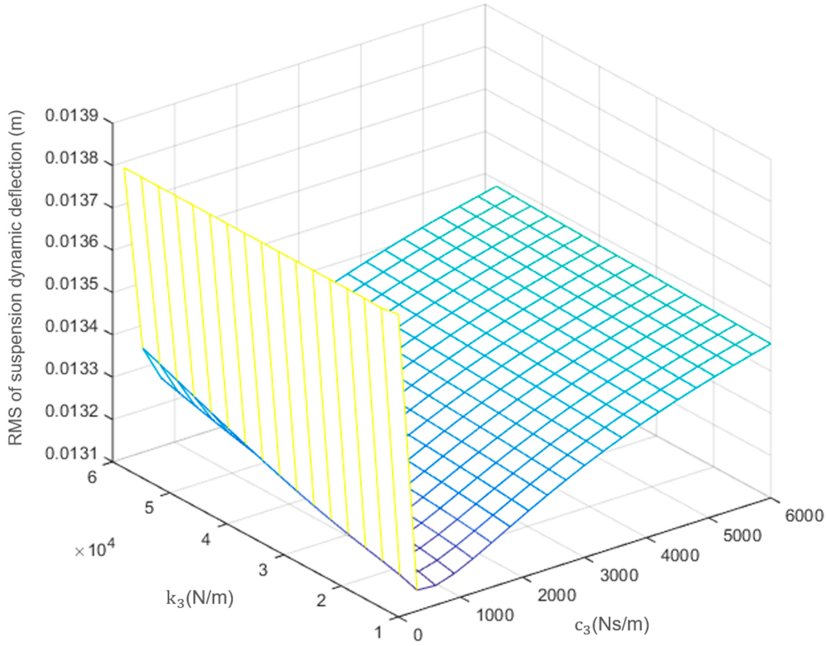
3.2. Parameter Optimization

Based on the vibration model with three degrees of freedom introduced above, we can establish a multi-objective optimization model to quantitatively evaluate and optimize the design parameters. For a given vehicle chassis-by-wire, the wheel specifications, body mass, IWM mass, and PEM mass are all determined. Thus, the main parameters that affect ride comfort are the K&C values of suspension and the DVA. Springs and shock absorbers are both standard components. Considering the space limitations and geometry relationship of the close-to-wheel space, there is a certain constraint range for the K&C value, which is demonstrated in Equation (28). Therefore, taking the X sequence as the design variable and the Y sequence as the numerical constant, the relevant definition of the optimization objective function is as follows:
X = x 1 , x 2 , x 3 , x 4 = ( k 2 , c 2 , k 3 , c 3 )    
Y = y 1 , y 2 , y 3 , y 4 ) = ( k 1 , m 1 , m 2 , m 3
m i n σ z ¨ 2 ( X , Y ) , σ F d ( X , Y ) , σ ( z 2 z 1 ) ( X , Y )  
s . t k 1 = 225,000 m 1 = 65 m 2 = 410 m 3 = 8 12,000 k 2 50,000 300 c 2 3000 10,000 k 3 30,000 300 c 3 2000    
Considering the optimization of three objective functions simultaneously, we apply an improved genetic algorithm for a solution, which has a balanced performance in calculating speed and accuracy. We set the population size to be 30, the crossover rate of the multi-point crossover function to be 80%, and the mutation rate to be 20%. We operate iteratively until convergence to obtain a set of Pareto Fronts, as shown in Figure 9. We can see that the initial state parameters did not reach the Pareto optimal state, and a set of optimized results was obtained with the iteration of the algorithm. Based on this, considering the performance of the three indicators comprehensively, the optimized state presented in Figure 9 is selected as the final design scheme. The specific values of the optimized variables are shown in Table 2.

3.3. Comparison and Discussion

For a performance comparison, we take four configuration schemes in the study, namely a separated type configuration, integrated type configuration, initial DVA configuration, and optimized DVA configuration, assuming that the wheel specifications, body mass, IWM mass, and PEM mass are all the same. The power spectrum density (PSD) of the vehicle body acceleration, wheel dynamic load, and suspension dynamic deflection can be described as indicators. We simulate the amplitude–frequency response curves, as shown in Figure 10, Figure 11 and Figure 12.
In Figure 10, Figure 11 and Figure 12, we can see that the system response has two resonance peaks, which are the chassis characteristic frequency and wheel characteristic frequency, respectively. The chassis characteristic frequency is around 1 Hz, where all four configurations show a similar performance. The wheel characteristic frequency is around 7 Hz, where the DVA configurations show an obvious decrease in the resonance peak value. The optimized DVA configuration performs best in all three indicators of ride comfort, especially with a diminished wheel characteristic frequency resonance peak. The maximum value of the optimized DVA configuration appears at the chassis characteristic frequency point, which is 0.56 (m/s2)2/Hz of vehicle body acceleration, 0.24 N2/Hz of wheel dynamic load, 5.85 mm2/Hz of wheel dynamic load, respectively. The sensitive frequency range of the human body is 4~8 Hz [18], where the optimized DVA configuration shows a good vibration performance. The resonance peak at the wheel characteristic frequency is diminished, and the PSD curve maintains a stable decrease in that frequency range.

4. Simulation Performance

For a detailed engineering design, we built a digital virtual prototype, as shown in Figure 13. According to the road condition definition of C-level pavement, we take vertical displacement as an input into the system. In order to view the time-domain performance clearly, the vertical displacement is assumed as a standard sine wave.
When the vehicle is driving, the chassis-by-wire system goes up and down with the wheel. In the simulation of the virtual prototype, we take a close look at the velocity and acceleration of the IWM, PEM, and vehicle body, respectively. The time-domain curves are shown in Figure 14, Figure 15 and Figure 16, respectively. In terms of the vehicle body, the optimized DVA configuration sees an 11.6% decrease (from 0.043 m to 0.038 m) in displacement and a 52.7% decrease (from 14.1 m/s2 to 6.8 m/s2) in acceleration when compared to the initial state. In terms of the IWM, the optimized DVA configuration sees a 33.5% decrease (from 0.0218 m to 0.0145 m) in displacement and a 51.9% decrease (from 7.9 m/s2 to 3.8 m/s2) in acceleration when compared to the initial state. In terms of the vehicle body, the optimized DVA configuration sees a 33.3% decrease (from 0.018 m to 0.012 m) in displacement and an 18.9% decrease (from 1.86 m/s2 to 1.51 m/s2) in acceleration when compared to the initial state. During the whole process, the IWM and PEM are both in an acceptable vibration state, which avoids the risk of spatial interference during vehicle driving.
During the working process, although the PEM does not bear the load directly, the cumulative vibration caused by the road roughness will lead to fatigue damage to the PEM. For the PEM serving as a DVA, this kind of vibration accumulation is particularly significant. Therefore, it is necessary to conduct a frequency sweep analysis to check whether the PEM has a large enough tolerance range and can avoid resonance at different frequencies. We import the virtual prototype into the finite element analysis software and load the swept frequency vibration along the x-axis, y-axis, and z-axis, respectively, as shown in Table 3.
The data results in Table 3 show that there is no resonance phenomenon in the system during the whole process of swept frequency. The PEM housing and structural parts are made of ADC12 material, with a yield strength of 170 Mpa and a tensile strength of 230 MPa. The analysis results of the swept frequency vibration prove that the system amplitude in the total range from 50 Hz to 800 Hz can meet the strength requirements of materials, which ensures a robust hardware carrier for the chassis-by-wire system.

5. Conclusions

This paper proposes a novel PEM, which is installed in a close-to-wheel position as a DVA for the chassis-by-wire system. According to the theoretical calculation and virtual prototype simulation, several conclusions can be drawn, as follows:
(1)
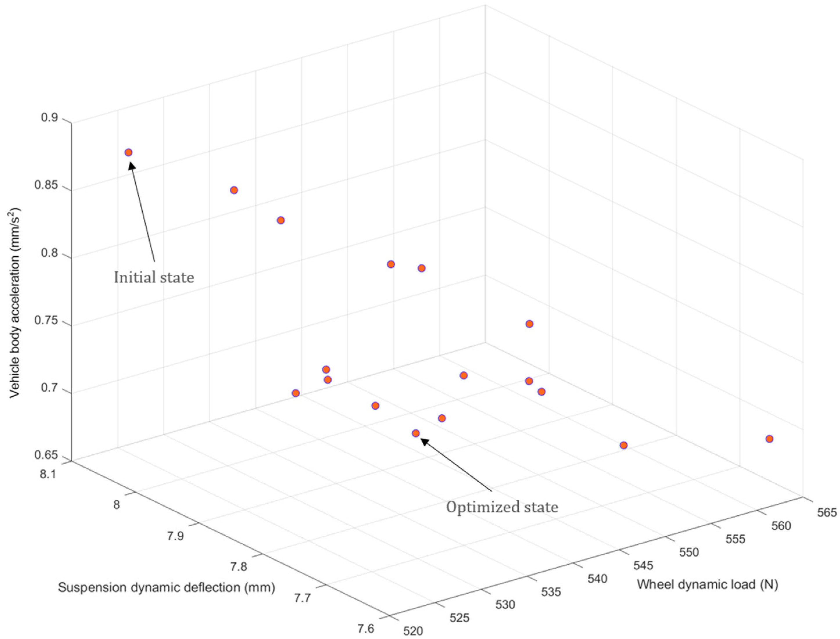
The DVA stiffness and damping have a direct impact on ride comfort performance, which can be calculated and optimized mathematically as a typical multi-objective optimization model.
(2)
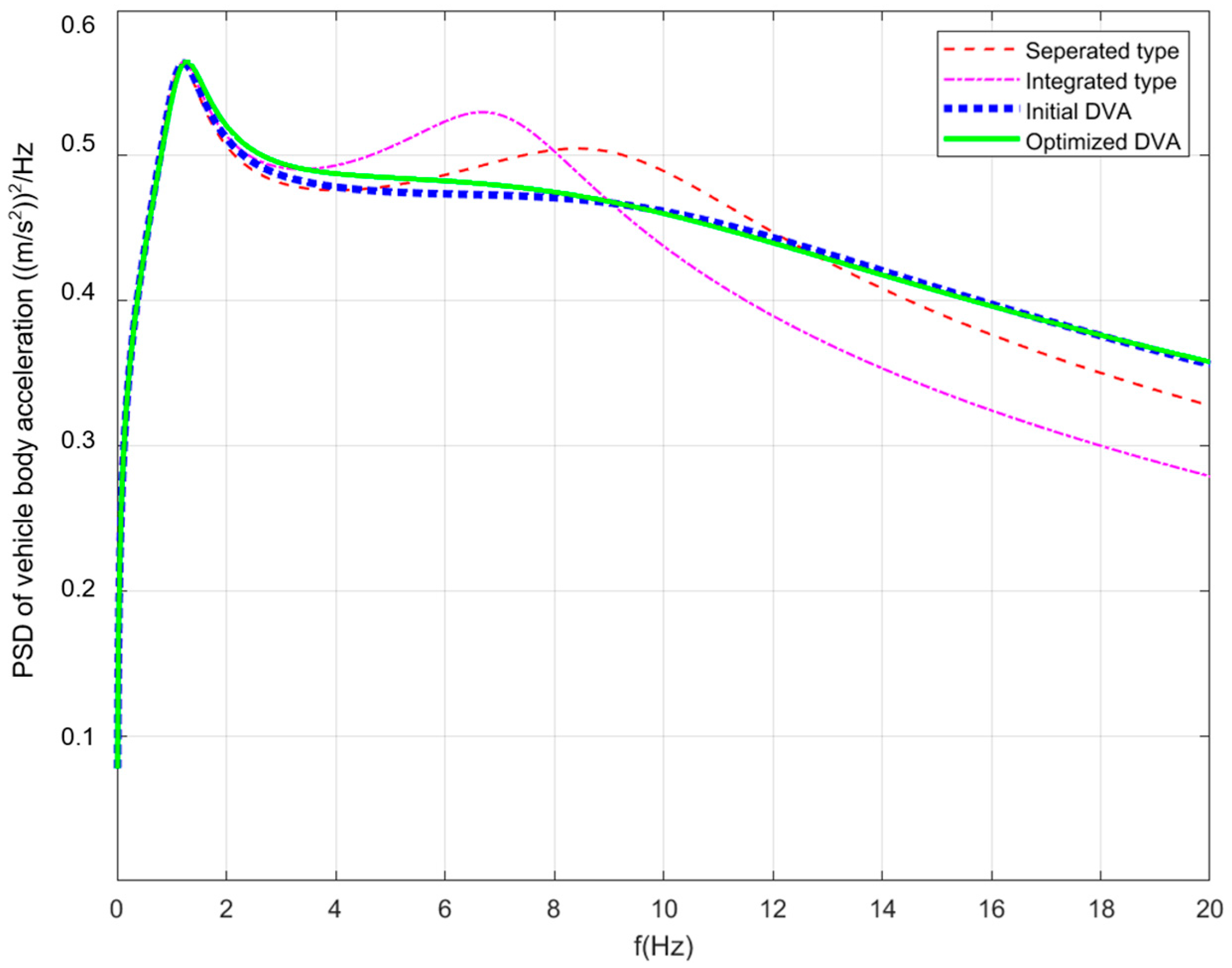
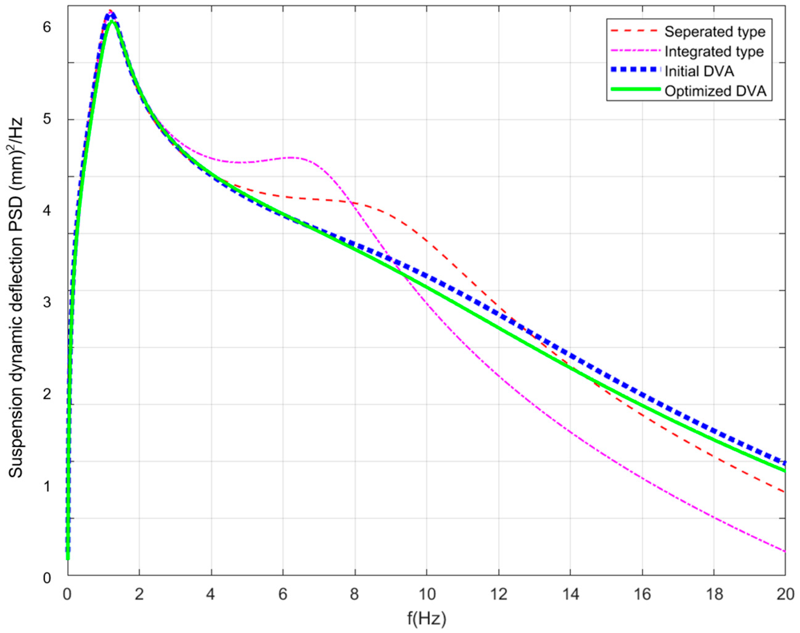
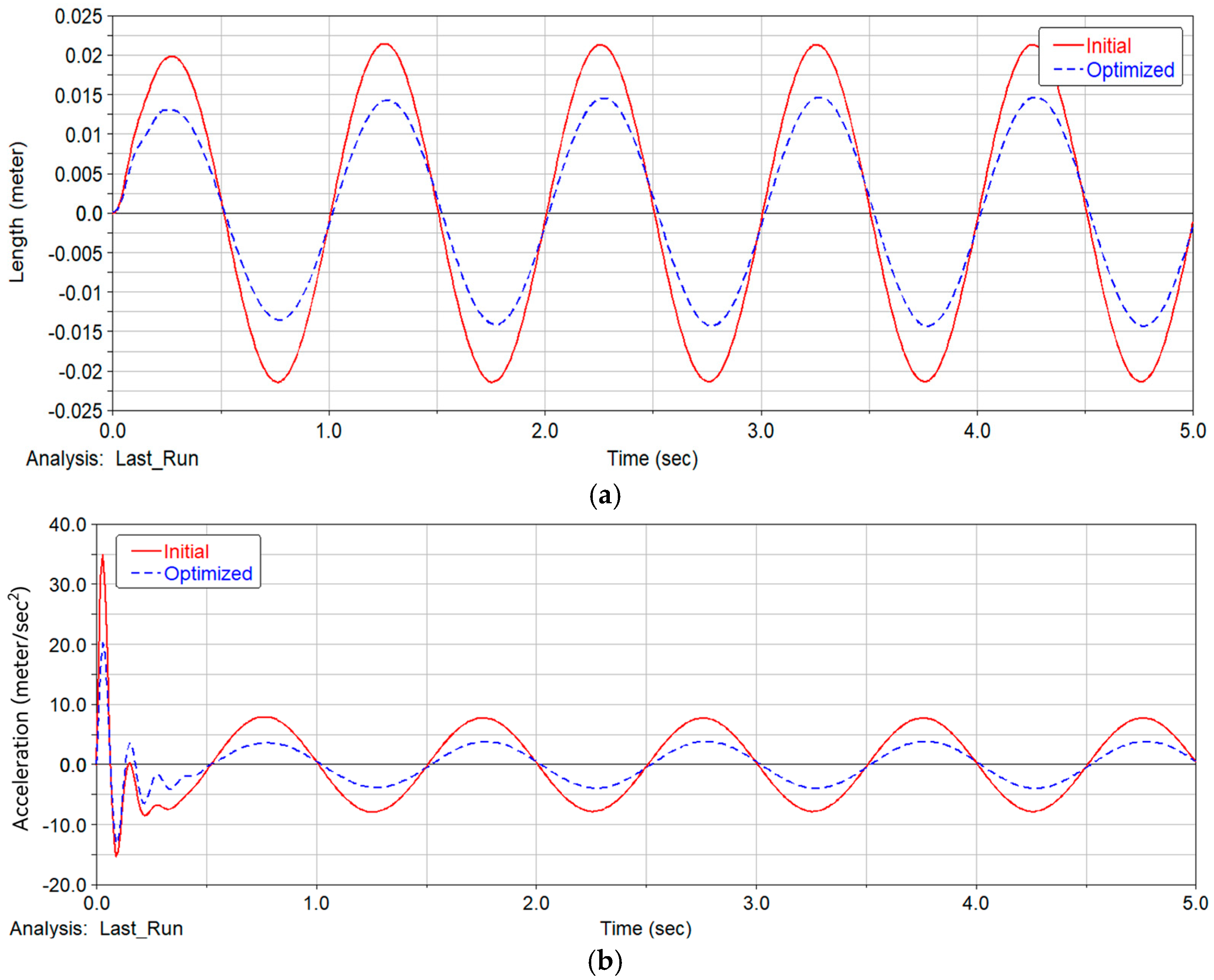
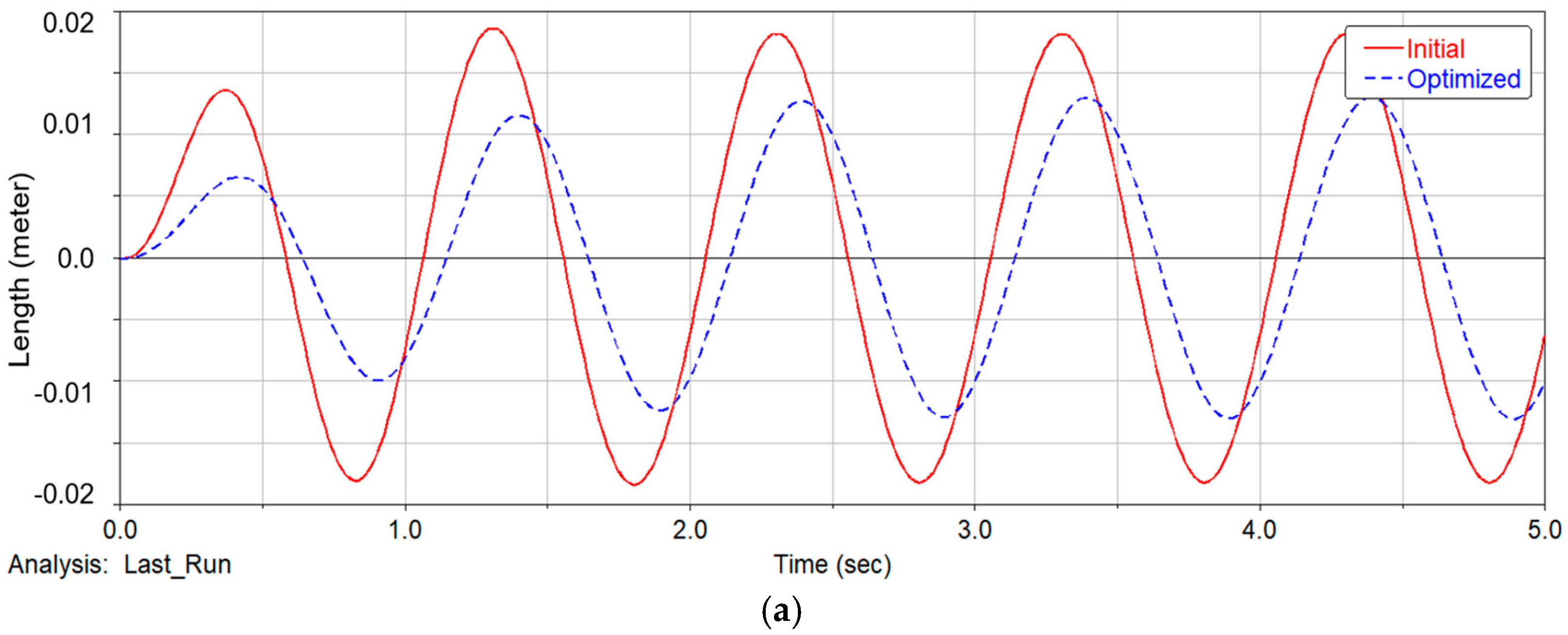
As a comparison, we take four configuration schemes in this study, namely, a separated type configuration, integrated type configuration, initial DVA configuration, and optimized DVA configuration. We take the condition of a vehicle driving at a speed of 15 m/s on a C-class road, with the simulation results showing the expected advantage of the optimized DVA configuration in ride comfort.
(3)
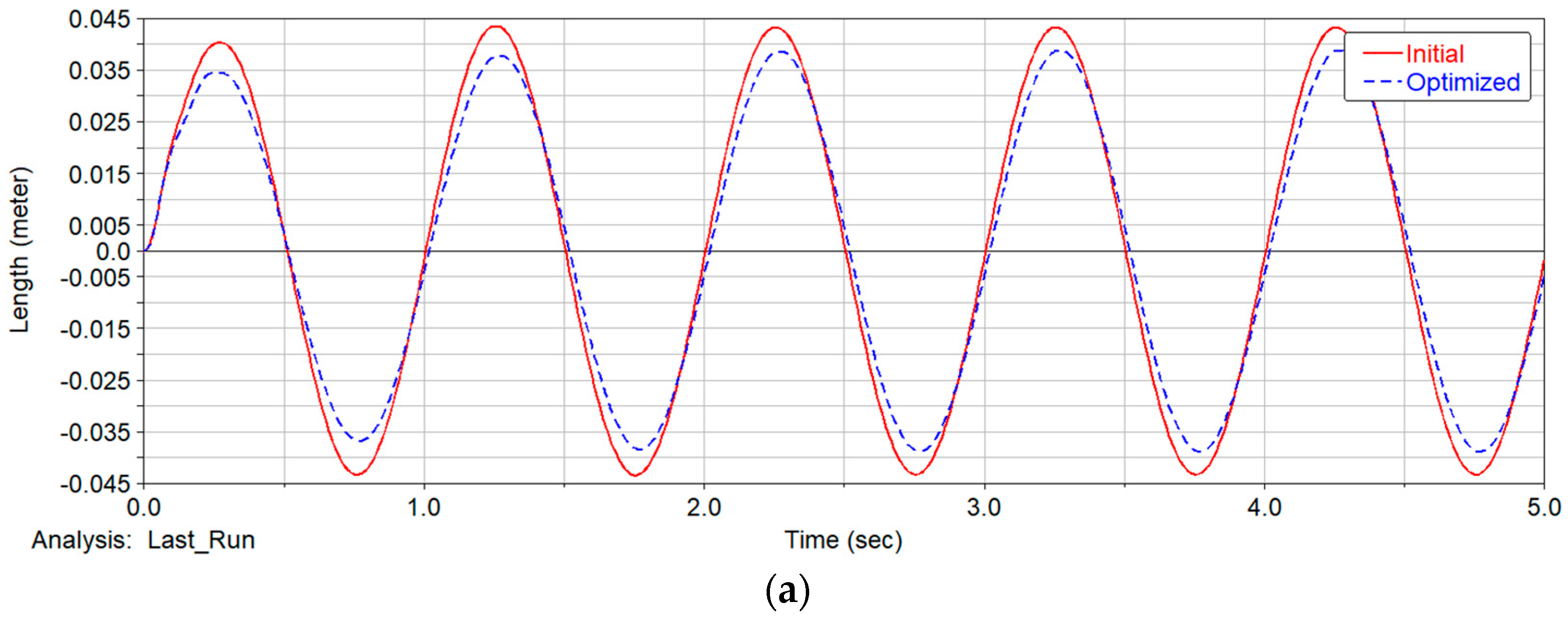
We built a digital virtual prototype for detailed engineering design. The simulation results show that the optimized DVA configuration shows obvious suppression in component vibration compared to the initial state, including the vehicle body, the IWM, and the PEM. The negative effect of un-sprung mass is effectively mitigated, and ride comfort is obviously improved. At the same time, a frequency sweep analysis of the PEM shows a robust result, which ensures a reliable connection for the chassis-by-wire system.
(4)
In the future, we have more work to do in the active control of DVAs. When the elastic element is upgraded with active actuators, the chassis-by-wire system can have a better performance in various road conditions. This technical route is especially suitable for autonomous driving technology, for the sensing information in the VCU can benefit the DVA system in mode recognition and active control strategy. The fundamental principles of vibration revealed in this paper can be a useful reference for the study of active DVA systems in the future.

6. Patents

The work reported in this manuscript applied for a China patent in 2024. The patent is titled as follows: A power electronic module with dynamic vibration absorption function, electric drive system, and vehicle. The corresponding patent number is CN117799372A.

Author Contributions

Conceptualization, X.C. and X.D.; methodology, X.D. and W.W.; software, W.W.; validation, X.D. and W.W.; formal analysis, X.D.; investigation, X.D. and W.W.; resources, X.C. and X.D.; data curation, X.D. and W.W.; writing—original draft preparation, X.D.; writing—review and editing, X.C.; visualization, X.D.; supervision, X.C.; project administration, X.C.; funding acquisition, X.C. All authors have read and agreed to the published version of the manuscript.

Funding

This research was funded by the National Natural Science Foundation of China project “Research on the Mechanism Principle and Multi-source Information Processing Mechanism of a Load-sensing Distributed Drive System” (No. 5227052034).

Data Availability Statement

The data presented in this study are available on request from the corresponding author.

Conflicts of Interest

The author Xiaoyu Ding was employed by the company R&D Innovation Headquarters, SAIC Motor. The remaining authors declare that the research was conducted in the absence of any commercial or financial relationships that could be construed as a potential conflict of interest.

Nomenclature

PEMPower electronic module
DVADynamic vibration absorber
VCUVehicle control unit
IWMIn-wheel motor
MCUMotor control unit
IGBTInsulate-gate bipolar transistor
RMSRoot mean square
PSDPower spectrum density

References

  1. Arango, J.F.; Bergasa, L.M.; Revenga, P.A.; Barea, R.; López-Guillén, E.; Gómez-Huélamo, C.; Araluce, J.; Gutiérrez, R. Drive-by-wire development process based on ROS for an autonomous electric vehicle. Sensors 2020, 20, 6121. [Google Scholar] [CrossRef]
  2. Ahmad, I.; Ge, X.; Han, Q.L. Decentralized dynamic event-triggered communication and active suspension control of IWM. IEEE/CAA J. Autom. Sin. 2022, 8, 971–986. [Google Scholar] [CrossRef]
  3. Jung, H.S.; Sul, S.K. Decomposed current controller for a paralleled inverter with a small interfaced inductor. IEEE Trans. Power Electron. 2018, 34, 9316–9328. [Google Scholar] [CrossRef]
  4. Couture, P.; Francoeur, B.; Simard, J.; Bourgeois, F.X.; Harbec, G.; Hydro Quebec. Electrically motorized wheel assembly. U.S. Patent 5438228, 1 October 1995. [Google Scholar]
  5. Pedro, J.; Weinholtz, J.; Sousa, L.; Reis, L. A New Concept for a Wheel-Embedded Assembly for Electric Vehicles. J. Mech. Des. 2013, 135, 124502. [Google Scholar] [CrossRef]
  6. Xing, C.; Zhu, Y.; Wang, J.; Lin, Y. Braking torque distribution reconfiguration strategy of vehicle with faults of in-wheel motor drive system. IEEE Trans. Intell. Transp. Syst. 2024, 25, 14476–14485. [Google Scholar] [CrossRef]
  7. Perovic, D.K. Making the impossible, possible—Overcoming the design challenges of In-Wheel Motors. World Electr. Veh. J. 2012, 5, 514–519. [Google Scholar] [CrossRef]
  8. Drexler, D.; Hou, Z. Simulation analysis on vertical vehicle dynamics of three in-wheel motor drive configurations. Proc. Inst. Mech. Eng. Part D J. Automob. Eng. 2023, 238, 2105–2119. [Google Scholar] [CrossRef]
  9. Nagaya, G.; Wakao, Y.; Abe, A. Development of an in-wheel drive with advanced dynamic-damper mechanism. JSAE Rev. 2003, 24, 477–481. [Google Scholar] [CrossRef]
  10. Gashi, R. Electric Steering System for Vehicle. WO Patent 006776A1, 26 August 2007. [Google Scholar]
  11. Trancossi, M.; Pascoa, J.C. Optimized modular design for energy efficiency: The case of an innovative electric hybrid vehicle design. In ASME International Mechanical Engineering Congress and Exposition; American Society of Mechanical Engineers: New York, NY, USA, 2016. [Google Scholar] [CrossRef]
  12. Höfer, A. Methodical conception and development of innovative lightweight chassis systems illustrated by the example of the “LEICHT” concept. In 5th International Munich Chassis Symposium 2014: Chassis. Tech Plus; Springer Fachmedien Wiesbaden: Wiesbaden, Germany, 2014. [Google Scholar] [CrossRef]
  13. Chen, X.; Yin, J.; Wang, W.; Wu, L.; Tang, F. Approaches to diminish large unsprung mass negative effects of wheel side drive electric vehicles. J. Adv. Mech. Des. Syst. Manuf. 2016, 10, JAMDSM0064. [Google Scholar] [CrossRef]
  14. Ding, X.; Chen, X. A power Electronic Module with Dynamic Vibration Absorption Function, Electric Drive System, and Vehicle. China Patent CN117799372A, 11 January 2024. [Google Scholar]
  15. Heintzel, A. Developing innovations: Chassis from steer-by-wire to AI. In Proceedings of the 5th International Munich Chassis Symposium, Munich, Germany/Virtually, 4–5 June 2024. [Google Scholar]
  16. Tavella, D.; Tolkacz, J.; Wasacz, B.; Peraboni, D.; Corradi, R. Cross-Domain Control Architecture—Single Master Controller for Propulsion and Chassis Automotive Domains; SAE Technical Paper Series; SAE International: Warrendale, PA, USA, 2022. [Google Scholar] [CrossRef]
  17. Joseph, J.; Joseph, J.; Rajendran, K.S.; Anoop, M.S. Structural design of ultimate terrain electric vehicle suspension system. In Applications of Computation in Mechanical Engineering: Select Proceedings of 3rd International Conference on Computing in Mechanical Engineering (ICCME 2021), Cochin, India, 22–24 September 2021; Springer Nature: Singapore, 2022. [Google Scholar] [CrossRef]
  18. Qin, Y.; Wang, Z.; Yuan, K.; Zhang, Y. Comprehensive analysis and optimization of dynamic vibration-absorbing structures for electric vehicles driven by In-Wheel Motors. Automot. Innov. 2020, 3, 254–262. [Google Scholar] [CrossRef]
Figure 1. Drive-by-wire configuration schemes. (a) Separated type configuration; (b) integrated type configuration; and (c) DVA type configuration.
Machines 12 00932 g001
Figure 2. System composition of PEM as DVA configuration. 1. Wheel subsystem; 1-1. Tire; 1-2. IWM housing; 1-3. Motor low-voltage signal connector; 1-4. Motor high-voltage three-phase connector; 1-5. Upper connecting brackets; 1-6. Lower connecting brackets; 2. PEM subsystem; 2-1. PEM upper cover; 2-2. PEM housing; 2-3. VCU signal connector; 2-4. Battery power connector; 3. Suspension subsystem; 3-1. Upper control arm; 3-2. Lower control arm; 3-3. Suspension spring and damper.
Machines 12 00932 g002
Figure 3. Composition and structure of PEM. 2-1. PEM upper end cover; 2-2. PEM housing; 2-5. three-phase high-voltage connector; 2-6. MCU low-voltage connector; 2-7. PEM damper; 2-8. PEM spring; 2-9. spring seat.
Machines 12 00932 g003
Figure 4. Schematic diagram of the chassis-by-wire mechanism.
Machines 12 00932 g004
Figure 5. Vibration model with three degrees of freedom.
Machines 12 00932 g005
Figure 6. RMS of vehicle body acceleration with DVA stiffness and damping.
Machines 12 00932 g006
Figure 7. RMS of wheel dynamic load with DVA stiffness and damping.
Machines 12 00932 g007
Figure 8. RMS of suspension dynamic deflection with DVA stiffness and damping.
Machines 12 00932 g008
Figure 9. Pareto Front of mathematical optimization.
Machines 12 00932 g009
Figure 10. PSD of vehicle body acceleration.
Machines 12 00932 g010
Figure 11. PSD of wheel dynamic load.
Machines 12 00932 g011
Figure 12. PSD of suspension dynamic deflection.
Machines 12 00932 g012
Figure 13. Virtual prototype.
Machines 12 00932 g013
Figure 14. Time-domain curve of the vehicle body. (a) Vertical displacement of vehicle body and (b) vertical acceleration of vehicle body.
Machines 12 00932 g014aMachines 12 00932 g014b
Figure 15. Time-domain curve of IWM. (a) Vertical displacement of IWM and (b) vertical acceleration of IWM.
Machines 12 00932 g015
Figure 16. Time-domain curve of PEM. (a) Vertical displacement of PEM and (b) vertical acceleration of PEM.
Machines 12 00932 g016aMachines 12 00932 g016b
Table 1. Passenger car parameters for simulation.
Parameter DefinitionAbbreviationUnitValue
Un-sprung massm1kg65
Sprung massm2kg410
DVA massm3kg16
Tire stiffnessk1N/m225,000
Suspension stiffnessk2N/m25,000
Suspension dampingc2Ns/m1800
Table 2. Mathematical solutions of the optimized parameters.
k2 (N/m)c2 (Ns/m)K3 (N/m)c3 (Ns/m)
Initial state25,000180015,0001000
Optimized state22,825225813,8521668
Table 3. Frequency sweep analysis results.
x-axis direction loading with acceleration of 15 m/s2
Frequency (Hz)50100150200250300350400450500550600650700750800
Amplitude (MPa)23.828.231.333.536.338.339.542.445.846.347.545.141.838.339.540.4
y-axis direction loading with acceleration of 15 m/s2
Frequency (Hz)50100150200250300350400450500550600650700750800
Amplitude (MPa)20.525.228.630.333.435.236.638.442.144.543.841.738.333.935.736.3
z-axis direction loading with acceleration of 30 m/s2
Frequency (Hz)50100150200250300350400450500550600650700750800
Amplitude (MPa)30.237.442.345.449.552.855.457.763.661.957.552.853.955.658.559.2
Disclaimer/Publisher’s Note: The statements, opinions and data contained in all publications are solely those of the individual author(s) and contributor(s) and not of MDPI and/or the editor(s). MDPI and/or the editor(s) disclaim responsibility for any injury to people or property resulting from any ideas, methods, instructions or products referred to in the content.

