1. Introduction
In the machining process, the application of vibration can effectively improve the machining quality in some cases. In Ref. [
1], rotary vibration milling was achieved by vibrating a milling cutter on the machine tool spindle axis, in addition to its rotary motion. Moreover, the method was proven capable of producing better surface finishes on difficult-to-cut materials and reducing tool wear. Ref. [
2] used axial and torsional vibration-assisted tapping to reduce tapping torque, axial force, and temperature compared to conventional tapping without compromising the thread quality. In the process of tapping blind holes, Ref. [
3] used longitudinal–torsional vibration in the extrusion zone to enhance the machinability of Ti-6Al-4V, which improves the quality of extruded threads and increases the efficiency of thread machining. Ref. [
4] proposed a new process for the fabrication of a Ti-6Al-4V-alloy trapezoidal thread using low-frequency torsional vibration extrusion (LTVE) through a forming tap. Experimental verification indicated that the LTVE-forming process reduced the total form tapping torque. It also proved the method’s overall reliability and effectiveness and the underlying insights needed to guide thread manufacturing. Ref. [
5] investigated the effects of longitudinal low-frequency vibrations on the performance of the single-point incremental forming process for an aluminum alloy 1050 (AA1050) sheet. The low-frequency vibrations significantly reduced the forming force and improved the formed product’s geometric accuracy. In Ref. [
6], a vibration-assisted plastic-forming method was proposed, and its influence on the clutch hub-forming process was investigated. According to the study, the vibration frequency exerted a more significant effect on forming load reduction than vibration amplitude. In Ref. [
7], vibration improved the electromagnetic forming process. Reasonably adjusting the vibration amplitude further optimized the forming performance. This confirms that vibration assistance contributes to optimizing electromagnetic forming for higher-quality metal forming.
A conventional method for generating torsion vibrations is to install a vibration generator on the end of a motor axis or actuator. Here, an energy converter is used for the drive control of the vibration generator. Regarding structure complexity, the additional equipment is bigger in the axial direction, and all functional parts are connected in series. Thus, there is a lot of room for improvement in terms of structure.
Generally, most studies on FSPMs have focused on the improvement of torque smoothness. The torque ripple produced by the FSPM motor’s double-salient rotor is evident [
8,
9]. The properties of FSPM motors have led to numerous researchers focusing on analyzing the torque ripple of FSPM motors. Salient rotors with a modular rotor FSPM are compared with different excitation sources in Ref. [
10], and their average and cogging torques were examined. New constructions have been suggested by certain studies to reduce the torque ripple of the FSPM. In its study of the torque ripples of an FSPM, Ref. [
9] noted that the interaction between tangential and radial air gap harmonics generates the torque harmonics. The authors suggested a permanent magnet with a V shape that successfully reduced air gap harmonics. An H-type FSPM linear generator was suggested in Ref. [
11]. The average thrust force and efficiency were increased, while the force ripple was decreased using the Taguchi optimization technique. Ref. [
12] suggested a novel design strategy that enhanced the E-shaped FSPM linear motor to lessen force ripples. A unique subsequent pole E-core stator FSPM machine that lowers torque ripples and stator flux linkage was proposed in Ref. [
13]. To enhance FSPM performance, including torque ripple, a magnetic flux barrier was incorporated into a rotor in Ref. [
14]. These studies not only reduced the torque ripple but also showed the cause of the torque ripple. The change in reluctance during rotation led to torque ripples. This explains the basic idea used to control the torque ripple. Controllable reluctance produces controllable torque ripple.
Usually, after the motor structure is finalized, the change in reluctance is also confirmed. The only variable that affects reluctance is the rotor position. However, if there are multiple moving parts in the magnetic circuit, the reluctance can be controlled by combining the positions of multiple moving parts, for example, the dual-rotor motor. Ref. [
15] proposed a dual-rotor axial-flux permanent magnet machine for the operation of a counter-rotating propeller. The machine uses a special structure to adjust the air gap to balance the loads of two rotors. Ref. [
16] proposed a novel dual-rotor flux-switching generator. Uniform and non-uniform rotor poles are mainly studied to improve efficiency and torque output. Ref. [
17] proposed a dual-rotor axial-gap flux-switching permanent magnet machine with hybrid excitation. A dual rotor is usually used for counter-rotating. Refs. [
18,
19] compared three topologies of a dual-stator axial-field flux-switching motor to select the suitable motor for electrical vehicles. Ref. [
20] designed a dual-rotor FSPM machine. The dual-rotor motor realizes the dual-axis power output using two rotors installed at both ends of one stator. The two rotors are symmetric in terms of output. The magnetic field generated by the permanent magnet is shunted by the two rotors. Moreover, the overall reluctance of the motor is determined by the positions of the two rotors.
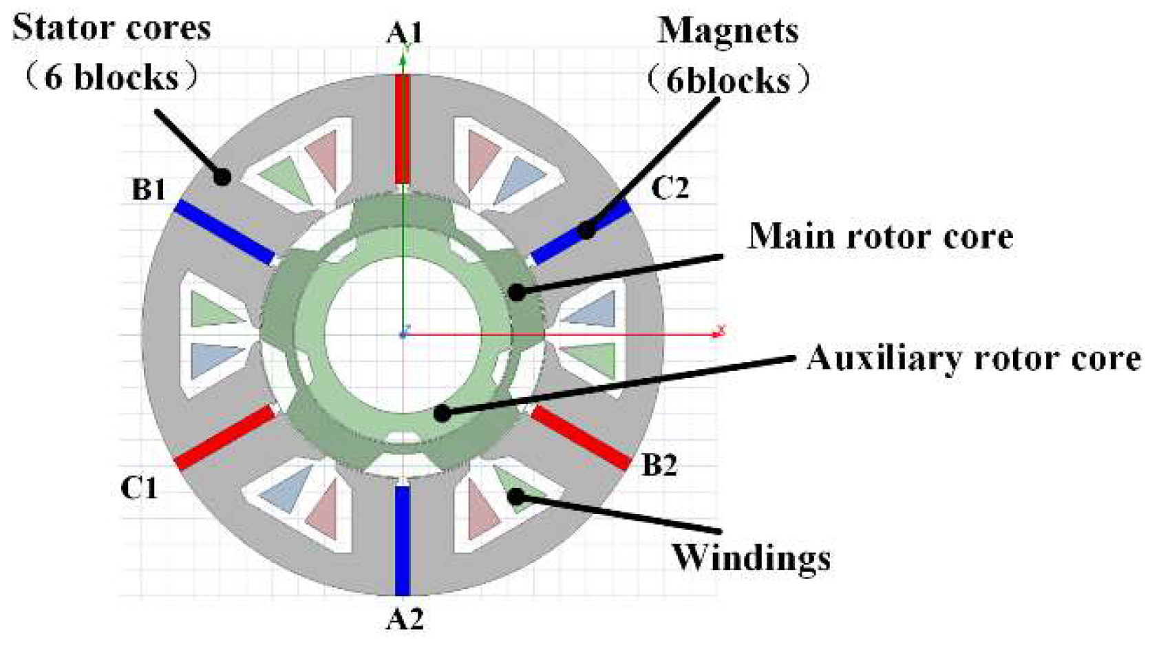
Inspired by the above studies, to realize the controllable torque ripple for the manufacturing process, an FSPM with an auxiliary rotor (AR-FSPM) is proposed, and its topology is shown in
Figure 1. Two rotors are coaxially installed in the stator: the main rotor (m-rotor) outputs power, and the auxiliary rotor (a-rotor) adjusts the torque ripple. The phase difference between the a-rotor and the m-rotor determines the reluctance value, thus adjusting the torque ripple. By producing controllable torque ripples, this model can provide more possible process schemes for different manufacturing methods.
2. Structure of the AR-FSPM Motor
The 6/5 (stator/rotor)-pole AR-FSPM section is shown in
Figure 1. Its effective axial length is 50 mm. There are three windings in the stator, which are marked as A, B and C. Each winding has two coils. Moreover, each coil is made up of 60 turns of copper wire. The three windings flow a three-phase AC to make the m-rotor rotate. The permanent magnets are installed between the adjacent stator cores. Moreover, the magnets at A1, C1 and B2 are clockwise magnetized tangentially. The others are anti-clockwise magnetized tangentially.
The motor section’s geometric dimensions are shown in
Figure 2. The geometric data sheet is shown in
Table 1.
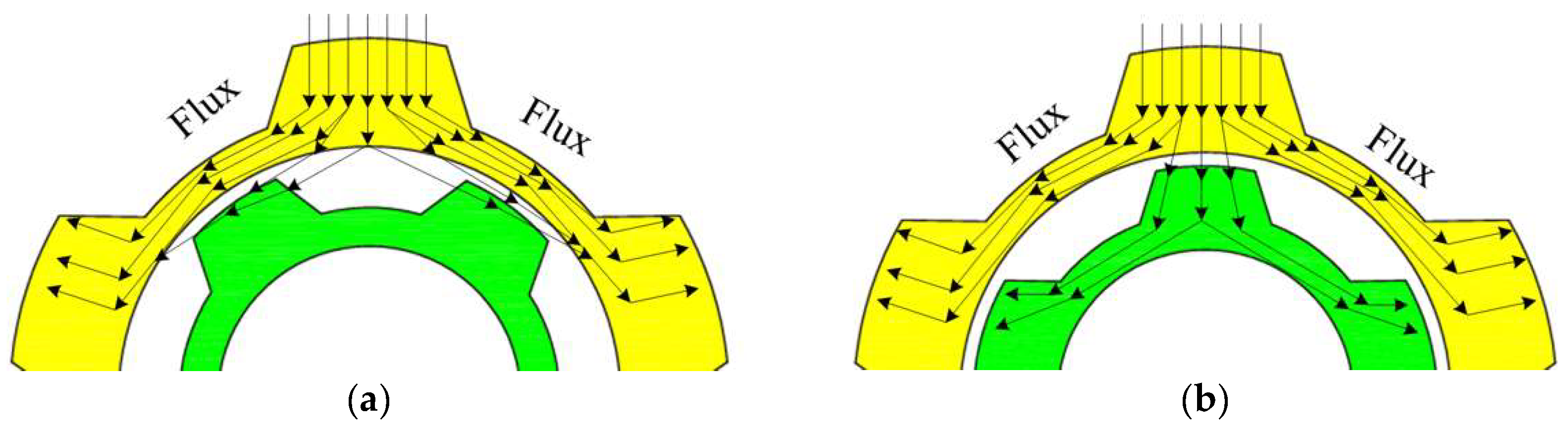
The power in the AR-FSPM is output via the m-rotor. A shunt function on the flux flow is produced by the m-rotor and a-rotor. The ratio of the flux flow path is influenced by the phase difference between the m-rotor and a-rotor salient. The m-rotor and a-rotor in
Figure 3a have a half-period phase difference. Only a small amount of flux passes through the a-rotor in this configuration, while the majority passes through the m-rotor. The reduction in the cross-sectional on the magnetic circuit increases the reluctance, which decreases the magnetic flux and, correspondingly, the output torque of the m-rotor. In
Figure 3b, the m-rotor and a-rotor are in the same phase. The a-rotor shunts a part of the flux. Then, this equivalently expands the cross-sectional of the magnetic circuit, thereby increasing the magnetic flux and the torque at this position. Thus, by controlling the relative speed between the two rotors, the torque ripple frequency can be adjusted.
According to the geometric parameters in
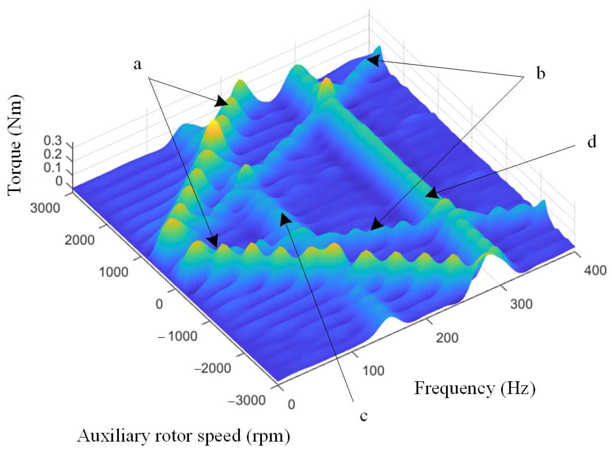
Table 1, FEM transient analysis is carried out on the ANSYS Electronics tool. The running speed of the m-rotor is set at 300 rpm. The current excitations have a constant q-axis current. In that case, the current waveforms are sine functions of the m-rotor position. In simulation, the phase current amplitude is set at 10 A. The a-rotor speed is set to range from −3000 to 3000 rpm with a step of 100 rpm. In the aspect of material configuration, DW465 is used for the stator core. C10 steel is used for the m-rotor and a-rotor. Copper is used for the coils. N35H is used for the permanent magnets. The length-based refinement is used for element meshing. Finally, the maximum element lengths are set to 0.5 mm for the rotors and stator, 1 mm for the magnet and 5 mm for other parts. The output torque spectrogram of the AR-FSPM is shown in
Figure 4.
In
Figure 4, the torque harmonic components at 150 Hz and 300 Hz are the 6th and 12th orders of m-rotor speed (electrical angle speed). They are related to the motor geometry size, and they are the inherent properties of the FSPM motor. The two V-shaped ridges are the first and second orders of the speed (electrical angle speed) difference between the m-rotor and a-rotor. These components are cleared and prove the feasibility of torque ripple frequency control. When the a-rotor and m-rotor rotate simultaneously, the motor outputs are nearly the same as those of the conventional FSPM motor. The speed difference is zero. Thus, the two V-shaped ridges in
Figure 4 do not appear in the case of the conventional FSPM motor.
The torque ripple amplitude is mainly related to the motors’ geometric sizes. Therefore, some specific parameters are analyzed via FEM in the next section.
4. The Coupling Effect of Torque Ripple of the AR-FSPM
As
Figure 4 shows, the harmonics caused by the m-rotor speed and the speed difference between the two rotors are almost independent. However, the harmonic may mix together in some cases: for example, the m-rotor and a-rotor run independently at speeds of 300 rpm and 2100 rpm or −1500 rpm. In those cases, the sixth-order harmonic of the m-rotor speed and first-order harmonic of the two-rotor difference are at the same frequency. The two waveforms overlap. The amplitude of the torque ripple at this frequency is determined by the two waveforms’ phase. Using the FEM model, the motor’s original geometric size is set as shown in
Table 1. The m-rotor runs at a speed of 300 rpm, and the a-rotor runs at speeds of 2100 rpm and −1500 rpm. In this motor, the mechanical angle is five times that of the electrical angle. Thus, the initial phase angle
θ between the m-rotor salient and a-rotor salient ranges from 0 to 72 degrees in a mechanical angle. The simulation step is 12 degrees. The torque performance is shown in
Figure 8.
According to the data from
Figure 8, the amplitude of the sixth-order harmonic of the torque ripple is related to the phase angle between the two rotors by twice the period. Three pairs of the waveforms overlapped. The waveforms of
θ = 0° and
θ = 36°,
θ = 12° and
θ = 48°,
θ = 24° and
θ = 60°. The 12th-order harmonic frequency is two times the 6th-order harmonic. The waveforms that overlap also exist in the 12th order harmonic and the pairs are the same as the sixth order harmonic. Thus, the amplitude of the 12th-order harmonic torque ripple is related to the phase angle between the two rotors by two multiples of the
θ period. When the m-rotor and a-rotor both run in the same direction, the amplitudes of the two overlapped waveforms can be experience-inducted and expressed by Equations (1) and (2).
where
Am6 is the amplitude of the sixth-order harmonics of the m-rotor speed without the influence of the a-rotor,
Aa1 is the amplitude of the first-order harmonic of the rotor speed difference without the influence of the m-rotor,
Am12 is the amplitude of 12th-order harmonic of the m-rotor speed without the influence of the a-rotor,
Aa2 is the amplitude of the second-order harmonic of the rotor speed difference without the influence of the m-rotor and
θa0 is the a-rotor’s initial position when the m-rotor salient is aligned with the winding phase A.
When the m-rotor and a-rotor run in opposite directions, the amplitude has a phase difference compared with Equations (1) and (2). Then, a signum function is added to Equations (1) and (2), which express the amplitude under different speed conditions; the results are shown in Equations (3) and (4).
where
ωa is the a-rotor speed and
ωm is the m-rotor speed.
In Equations (1)–(4),
θa0 presents the a-rotor’s initial position. To calculate the overlapped torque ripple at any rotor position,
θa0 can be expressed by Equation (5).
where
nr is the number of the rotor salient, and
θm is the m-rotor’s position.
5. Experiment Test of the AR-FSPM Motor
Based on the geometric data in
Table 1, a prototype of AR-FSPM was built, as shown in
Figure 9.
C10 solid steel was used to build the m-rotor core and a-rotor core. Then, 0.5 mm thick DW465 silicon steel laminates were used to make stator cores. A testing bed was built to verify the prototype. The configuration of the testing bed is shown in
Figure 10.
In the testing bed, an encoder is attached to the end of the AR-FSPM axis to feedback the m-rotor’s position. A servo motor is connected to the a-rotor to precisely perform position control. A torque sensor is used to connect the m-rotor and magnetic powder brake to measure the output torque. The prototype is driven by a regular permanent magnet synchronous motor driver, which generates the driven currents via the SVPWM method. By adjusting the magnet power brake, the phase current amplitude is set at 10 A during m-rotor rotation. Based on this platform, the experiments were carried out. Each test was run three times, and the results were averaged to exclude accidental errors.
5.1. The Rotary Speed and Torque Ripple Frequency Testing
In this test, the rotors’ speeds are arranged in four cases. In Cases 1 and 2, the m-rotor speed is set at 30 rpm, and the a-rotor speed is set at 60 and 120 rpm. In Case 3, the m-rotor runs at a speed of 30 rpm, and the a-rotor stops. In Case 4, the m-rotor stops, and the auxiliary is set at 60 rpm. The torque measurement data are calculated by FFT analysis, and the experiments and FEM result comparisons are shown in
Figure 11.
In
Figure 11, the results of the torque ripple experiment are basically consistent with the simulation results. When the m-rotor runs at a speed of 30 rpm, it generates harmonics at 15 Hz (6th harmonic) and 30 Hz (12th harmonic). The speed difference between the m-rotor and a-rotor results in two peaks in
Figure 11a–c. When the speed difference is 30 rpm, the two peaks are at 2.5 Hz (base frequency) and 5 Hz (2nd harmonic), as
Figure 11a,c show. When the speed difference is 60 rpm, the two peaks are at 5 Hz (base frequency) and 10 Hz (second harmonic), as
Figure 11d shows. When the speed difference is 90 rpm, the two peaks are at 7.5 Hz (base frequency) and 15 Hz (second harmonic), as
Figure 11b shows. The amplitude at 30 Hz is smaller than in the FEM test, which may be caused by the sensor dynamic response decreasing at a relatively high frequency.
The waveform overlaps in
Figure 11b, which gives the amplitude of 15 Hz harmonic a higher value. This phenomenon is tested in the next subsection.
5.2. The Torque Ripple Amplitude Testing
The m-rotor speed is set at 3 rpm, and the a-rotor speed is set at 21 rpm. The speed difference is six times the speed of the m-rotor. Before the test starts, the m-rotor salient aligns with the winding phase A. Then, the initial angle between the a-rotor and the m-rotor ranges from 0 to 72 degrees with a step of 6 degrees. Theoretically, the overlapped waveforms in the experiment are at 1.5 Hz (base frequency) and 3 Hz (second harmonic). The speed of the two rotors is constant during the test. Therefore, the frequency values of all torque ripples are the same for all tests. The main variation is the amplitude of the harmonics. Therefore, the harmonic amplitudes of the torque ripples are mainly studied, and the results are shown in
Figure 12.
In
Figure 12, the experiment results match the empirical equation and FEM results well. The sixth harmonic of the m-rotor speed overlapped the first harmonic of the two-rotor difference at 1.5 Hz, and it was two times the period of the a-rotor phase. Then, the 12th harmonic of the m-rotor speed overlapped the 2nd harmonic of the two-rotor difference at 3 Hz, and it was four times the period of the a-rotor phase. In fact, the prototype’s rotors were made of solid steel, and their losses reduced the torque value, which caused the measured value to be slightly less than the theoretical value. In general, when the speed difference was six times that of the m-rotor, by controlling the phase difference of the m-rotor and a-rotor, the overlapped torque ripple amplitude could be controlled in a certain range, which could provide the power source for torsion vibration.
6. Conclusions
A driven machine that can generate adjustable torsional vibrations has the potential to improve the driven force efficiency of manufacturing equipment and increase processing quality. For this purpose, a novel FSPM motor with an auxiliary rotor (AR-FSPM) is proposed. The rotor of the AR-FSPM motor is separated into two parts: the m-rotor and the a-rotor. The m-rotor outputs the torque, and the a-rotor adjusts the main harmonic frequency of the torque ripple. The influence of the geometric parameters of the a-rotor on the torque ripple amplitude was studied, and the patterns were determined. The split ratio of the two rotors has a significant effect on the amplitude of the torque ripple. When the two rotors’ speed difference is six times the m-rotor speed, the phase difference of the two rotors can affect the amplitude of the torque ripple. The related expression was established, and a prototype was built and tested. The results prove that the principle of this machine is feasible.
The machine proposed in this paper has a smaller size in the axial direction, and is a little wider in the radial direction. It requires a servo motor to control the a-rotor and more complex control methods. From the perspective of flexible manufacturing, the machine can provide more flexible vibration output to support different manufacturing needs.


