1. Introduction
In recent years, there has been growing interest in using additive manufacturing (AM) to incorporate bioinspired architectures into common heat exchangers [
1,
2,
3]. This allows for more compact and lightweight components, increasing the heat transfer area and improving the mechanical resistance, as highlighted in [
4,
5]. The new generation of heat exchangers, characterized by high heat transfer efficiency and small dimensions, is known as the Printed Circuit Heat Exchanger (PCHE) [
6]. This exchanger has found applications in various fields, including automotive, aerospace, and green energy production [
7]. AM is an innovative production technique that relies on the gradual and localized addition of material to shape the final part. Material is added in layers, using various techniques such as binder printing or laser melting, depending on the material being processed [
8,
9]. These new production techniques have achieved significant reliability and defect management [
10,
11], becoming reliable alternatives to standard production techniques, which typically involve material removal. One of the most important advantages of AM is the significant geometrical freedom it offers in component design [
12,
13]. Specifically, it enables the creation of highly complex and interlocking geometries while maintaining lower production costs compared to traditional methods [
14]. The use of bioinspired natural geometries has proven to be highly effective in enhancing the mechanical and thermal performance of conventional components [
15,
16]. Although many numerical studies have explored these geometries, they were nearly impossible to produce with standard manufacturing techniques [
17]. A representative example of a compact 3D-printed heat exchanger is presented in [
18]. In the current study, the authors aim to investigate in detail the fluid dynamic performance of heat exchangers, specifically those needed for the oil-lubricated bearings of large rotating machines, as discussed by the same authors in [
19].
In a previous work by Peng [
20], the gyroid lattice was identified as one of the most promising geometries among known natural structures. The research trend has been confirmed by many recent works, such as [
21]. This geometry was first discovered by biologist Alan Schoen in 1970 while studying the wing microstructure of C. Rubi butterflies [
22,
23]. From a mathematical perspective, the gyroid lattice is formalized as a triple periodic minimal surface (TPMS). In other words, given a specified boundary, the gyroid is the continuous surface that minimizes the total area and is periodic in space. The 3D surface can be modeled by the following equation:
where (
x,
y,
z) are the Cartesian coordinates. A key characteristic of the gyroid surface is its ability to divide space into two separate and continuously enveloped domains, significantly increasing the surface area for heat transfer and sustaining the turbulence regime of the coolant, as discussed in [
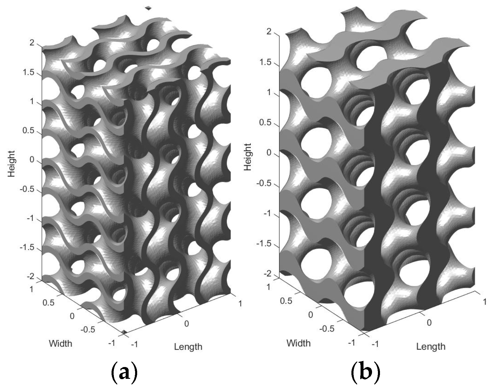
24]. Once the minimal surface is defined, the 3D lattice can be created in two ways: by thickening the surface wall (sheet topology) or by solidifying one of the two domains (solid topology), as shown in
Figure 1. The resulting lattices differ considerably from a fluid dynamic perspective, and they need further investigation. Three parameters must be defined to fully characterize the lattice structure: the lattice type (sheet or solid), the cell length (which is the dimension of the minimum repeatable cell), and the relative density (which is the ratio between the volume of the lattice and the volume of the bulk material).
The existing literature contains numerous studies comparing the mechanical and thermal performance of various bioinspired microstructures, such as gyroid, diamond, octet-truss, and Schwartz-D lattices. All the authors agree that the gyroid lattice has notable mechanical properties due to its lightweight nature [
25,
26,
27], and it guarantees the highest heat exchange when all other variables are held constant [
24]. Notably, Koneri et al. [
28] established a reliable procedure for quantifying and comparing the heat transfer properties of lattice geometries. They considered a circular pipe filled with the lattice geometries of interest, where heat flows from the hot walls to the coolant fluid. By imposing the coolant flow rate and the temperature of the external walls, several numerical fluid dynamic analyses were performed on the specimens. They found that the gyroid lattice can increase heat exchange by 50% compared to a plain cylindrical tube. This finding highlights the significant potential of the gyroid structure; however, there has been no investigation into how the design parameters of the lattice affect the fluid dynamic performance of the heat exchanger. This work aims to fill that knowledge gap.
Another important aspect to consider is that the gyroid lattice has the critical but beneficial property of self-sustainability during the manufacturing process. In other words, it can be easily printed layer by layer with additive manufacturing techniques without requiring external supports to bear its self-weight. This feature facilitates the integration of the gyroid lattice into components without particular constraints, as discussed by Parenti in [
29]. For manufacturing the samples, bound metal deposition (BMD) technology, an industrial implementation of the material extrusion process for metals, was chosen [
30,
31]. This innovative technique, based on metal-polymer feedstock extrusion and sintering, offers several advantages, such as powder-less printing (the feedstock filament is directly printed without the need for a powder bed [
32]). This eliminates the challenging task of removing residual powder from internal channels. Additionally, it is a low-cost and easy-to-use technique that allows the printing of different metals, including stainless steel and copper, which are widely used in heat exchangers. Moreover this technology is widely investigated to increase the final printing quality, as discussed in [
33].
The primary objective of this work is to compare the fluid dynamic properties of different gyroid lattices to provide insights for designing innovative bioinspired heat exchangers. The gyroid lattice is selected as the inner geometry, and a sensitivity analysis of key design parameters is developed and discussed. For the numerical analysis, the authors draw inspiration from the set-up described in [
28] and use it to characterize different gyroid lattice geometries. The focus is on three fluid dynamic properties: the pressure drop required for coolant circulation, the turbulence intensity ratio, and the heat exchanged by the fluid. An experimental validation is then performed. The lattice samples are printed using BMD technology, inspected for printing defects, and flushed with oil and water to validate the numerical model on the pressure drop. The lattice material used is either stainless steel or copper. Although the choice of solid materials and coolant fluids is related to their final application in oil-lubricated bearings, the results are of general interest.
The paper is organized as follows.
Section 2 describes the numerical model for predicting the fluid dynamic properties of gyroid lattice types.
Section 3 presents the most relevant results of the numerical model.
Section 4 focuses on the heat exchanged through conduction in the lattice walls and how this affects overall performance.
Section 5 outlines the procedure for metal 3D printing of the samples and the experimental set-up.
Section 6 presents the results of experimental flushing and the validation of the numerical model for pressure drop. Finally,
Section 7 discusses the results and conclusions of the comparative analysis. It also mentions a possible practical application of the considered topic, performed by the same authors in [
19].
2. Set-Up of Numerical Model for Fluid Dynamics
The analysis of the fluid dynamic properties of the gyroid lattice is performed by properly defining a computational fluid dynamics (CFD) model. The numerical simulations were performed using the software ANSYS Fluent, version 2021 R2. The simulations were performed under the hypothesis of steady-state conditions and an incompressible fluid. The thermal properties of the lubricant are a function of the local temperature.
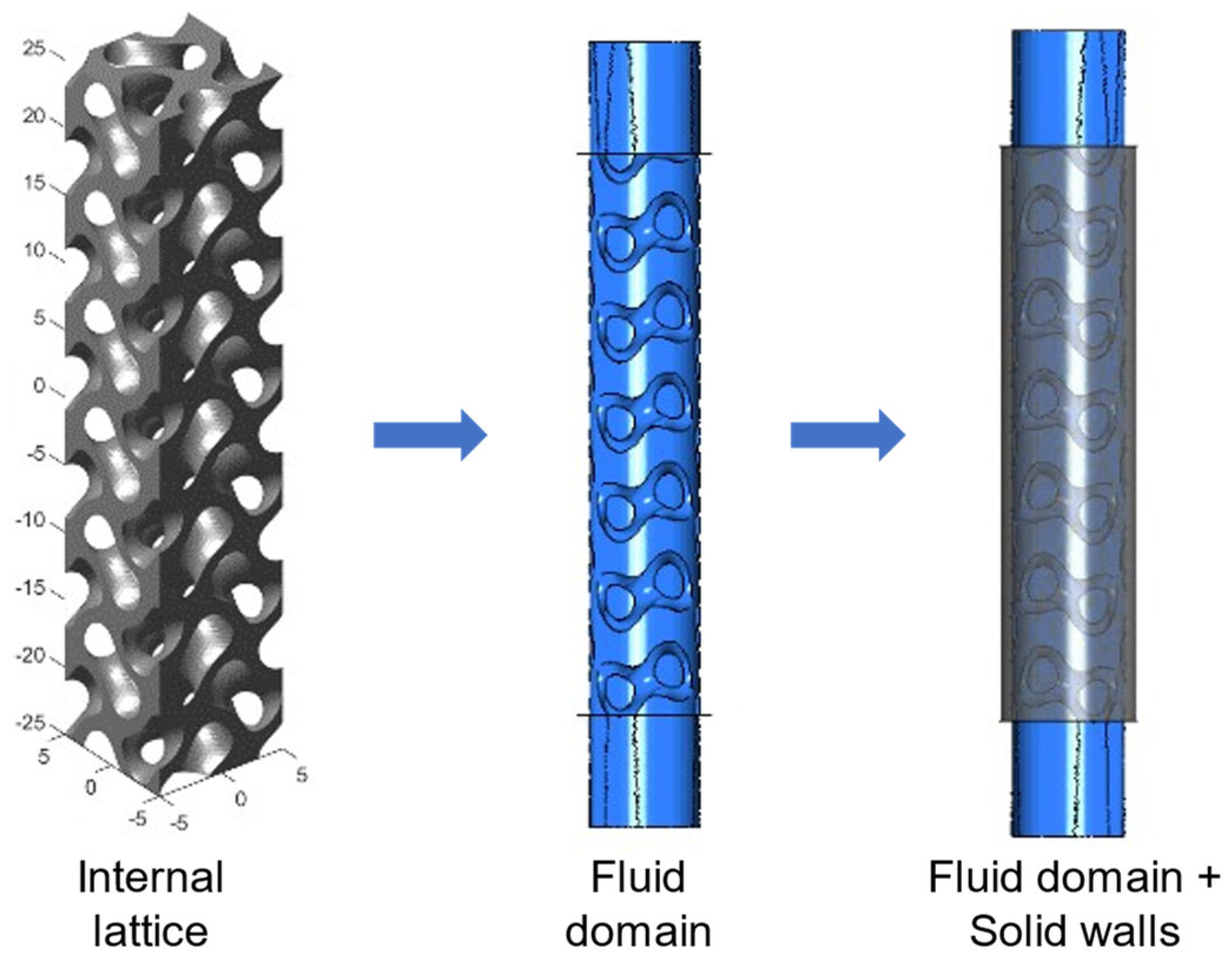
In order to create the model geometry, the gyroid lattice is firstly defined by means of the tool “MS Lattice”, developed by Al-Ketan [
25]. Then, the lattice geometry undergoes Boolean operations to create the liquid volume domain and the solid walls, as shown in
Figure 2.
The procedure to quantify the heat exchange performance for different printed lattices is widely discussed by Koneri et al. in [
28]. For the current study, the production steps are kept while the effective tube geometry is adapted to the current study. The representative sections of the heat exchanger have a cylindrical shape. The tubes have the following relevant dimensions: inner diameter is 10 mm, outer diameter is 14 mm, and tube length is 50 mm. Dimensions are chosen by considering interesting practical values and the printability capabilities of the available technology; nevertheless, the obtained results are useful for a comparative analysis and they are almost independent from the absolute dimensions. The tubes are filled with the gyroid lattice, and the design parameters are ranged. By considering the constraints for a reasonable design and to guarantee the printability, six lattice types are considered in the analysis with the following features: cell length = 8 mm is fixed, both sheet and solid topologies are considered, and relative density ranges between 15 and 45%. Cell length is chosen so that the minimum wall thickness in all the lattice domain is greater than 0.5 mm to guarantee printability. Other values of relative density are not considered since they will likely lead to excessively high pressure drop values or low heat exchange.
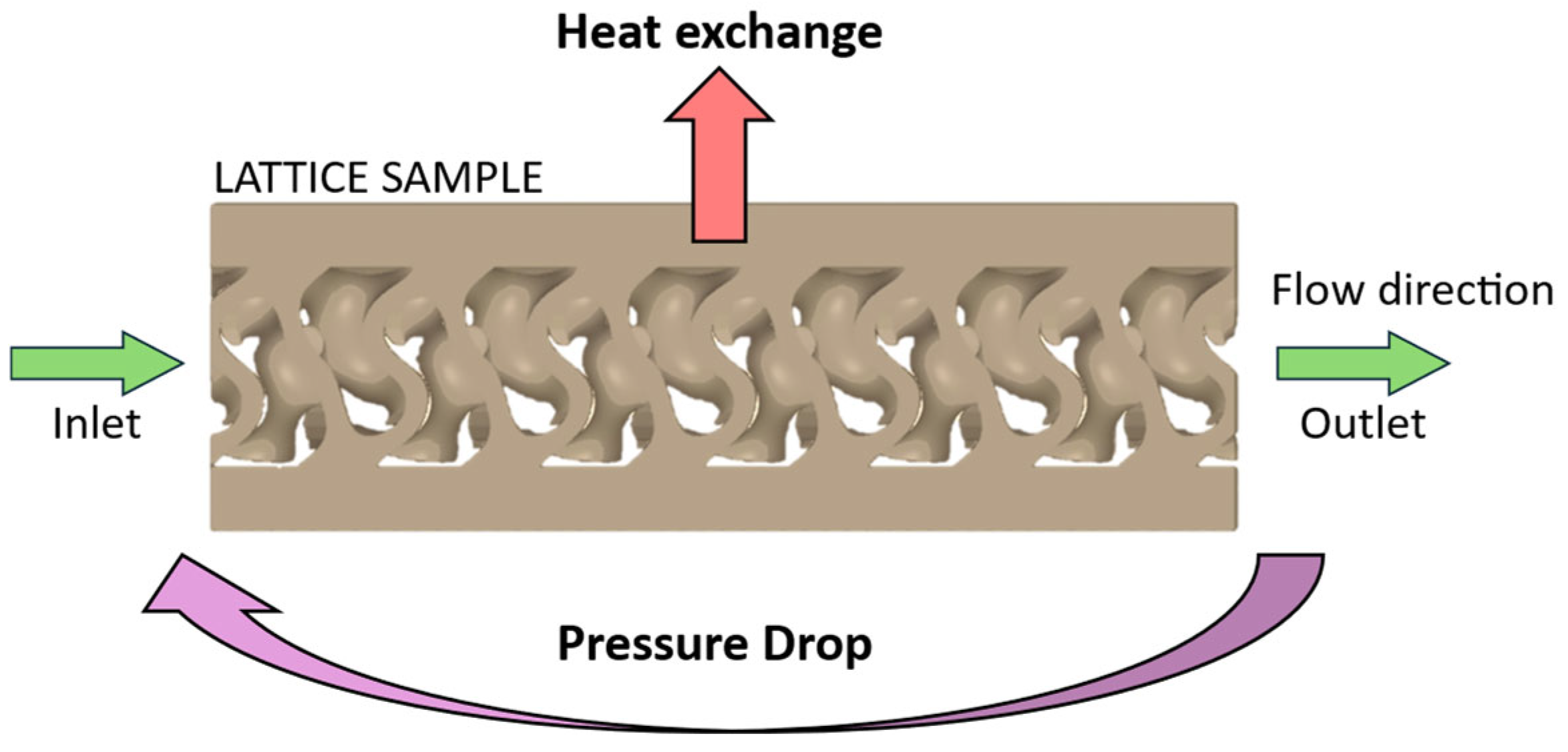
Table 1 summarizes the six geometries under consideration. A schematic representation of the resulting domain is shown in
Figure 3. The domains of interest are the solid part and the fluid one, calculated by Boolean operations.
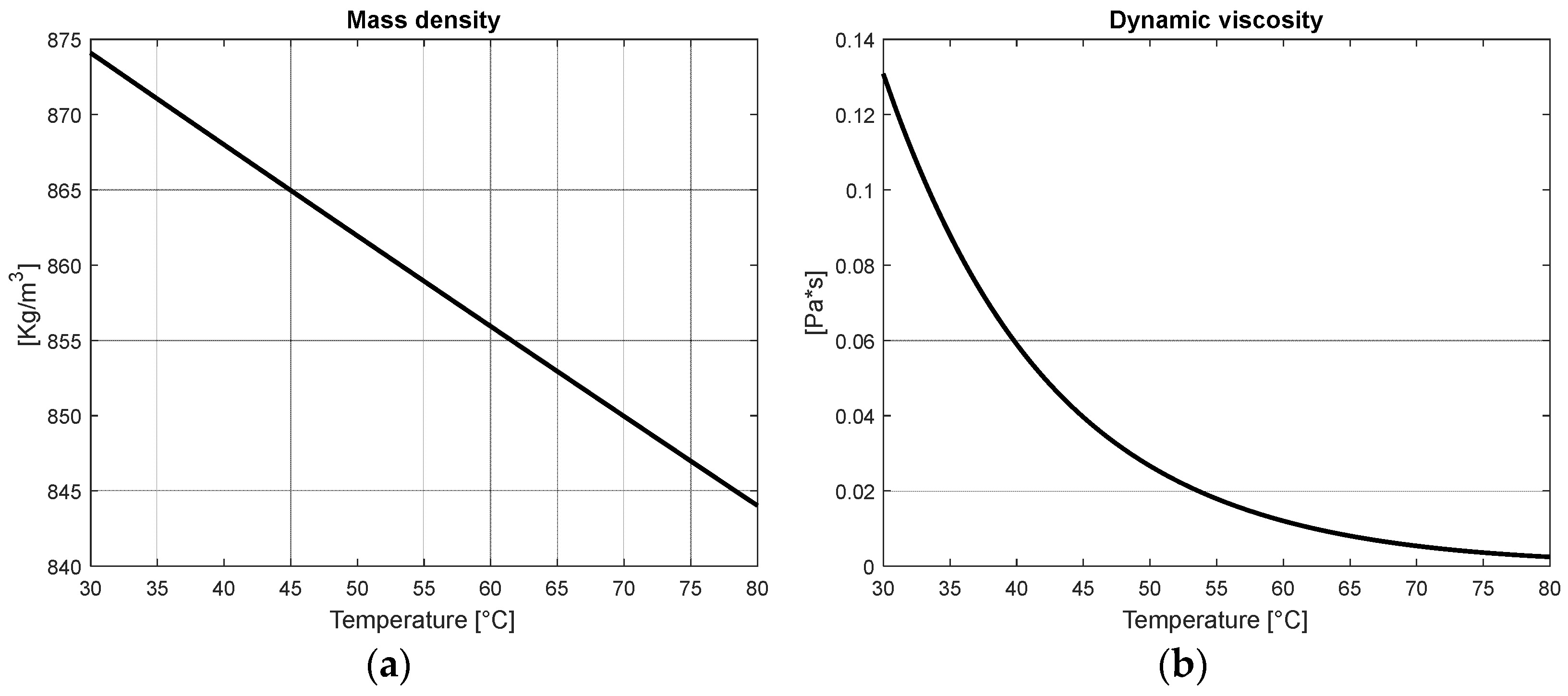
The considered material for the solid part is AISI-316L steel or copper, while the fluid domain is filled with ISOVG68 oil or water. The choice of the materials results from a study by the same authors of a practical case, widely discussed in [
19]. When oil is used, the numerical model should consider also the change in oil density and dynamic viscosity with respect to temperature, as shown in
Figure 4.
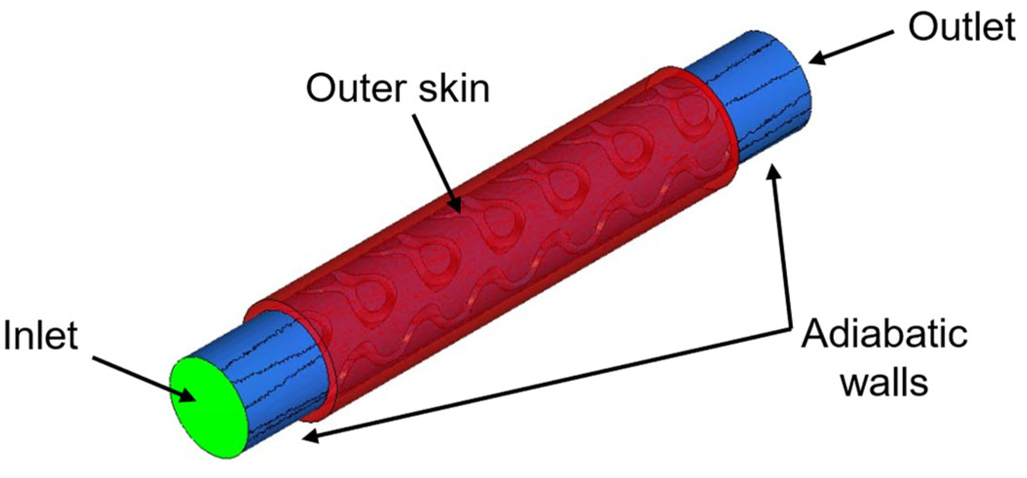
The boundary conditions (BCs) applied to the domain are imposed as done in [
28]; moreover, the used BCs can be easily reproduced during the experimental activities. Relevant surfaces are divided as shown in
Figure 5; in particular, flow rate is imposed at the inlet and atmospheric pressure at the outlet of the duct. For the heat exchange, temperature is imposed at the coolant entrance (40 °C) and on the outer skin surface (60 °C). All the not-mentioned walls are considered adiabatic. All the boundary conditions are summarized in
Table 2. Additional considerations must be made regarding wall roughness in additive manufacturing (AM) circuits. As stated by Hartsfield in [
34], estimating the flow characteristics of AM parts can be challenging. For the components analyzed in this study, the nominal geometry of the walls was used, with an average surface roughness of 22 µm derived from experimental measurements on the printed parts. No significant model issues were observed, due to the short and straightforward geometry of the channels.
The domain is divided with an unstructured tetrahedral mesh, edge size is approximately 0.25 mm, and total mesh is around 3.0 million elements. Local refinement is used in order to properly catch the geometry, and the inflation algorithm guarantees a good convergence of the solution on the wall boundary layer. Domain discretization is shown in
Figure 6.
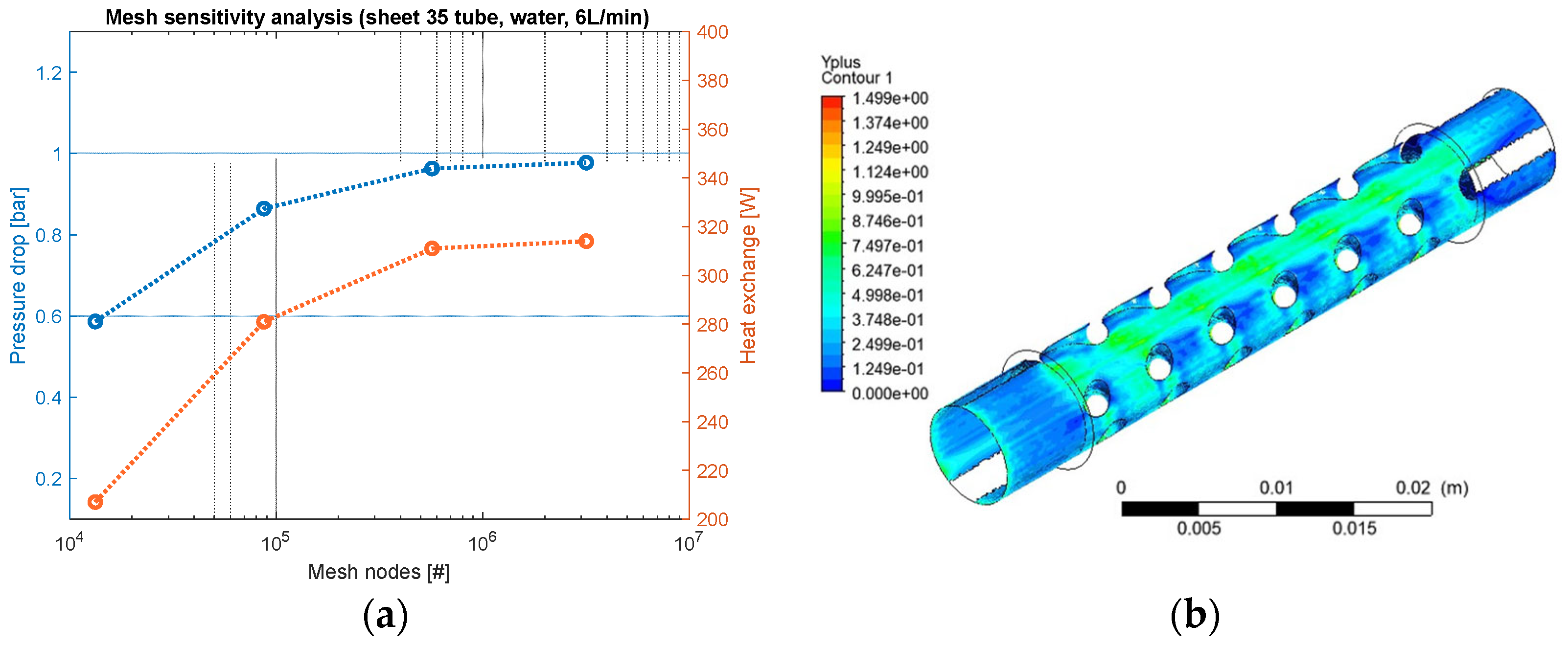
The Reynolds-averaged Navier–Stokes equations are solved by means of a pressure-based solver and k-ω SST turbulence model, as commonly done in this field. Grid convergence index (GCI) analysis is performed to check for numerical convergence. Cell length is reduced up to 0.25 mm (3.0 M elements) to reach the asymptotical trend of the results. The convergence is checked for the following quantities of interest, namely the pressure drop between the inlet and the outlet of the duct, and the integral heat exchanged by the outer skin surface, as shown in
Figure 7a. The residuals of the simulation are checked, and they ensure good convergence (relative error 10
−6). Moreover, the y+ value is checked at solid walls to be lower than unity, as proof of boundary layer correct modeling, as shown in
Figure 7b. The convergence analysis is repeated for all the simulations. Once the model is correctly set up, simulations are repeated by changing the coolant type (oil/water) and the flow rate of the coolant (1–6 L/min). For each configuration, the pressure drop, heat flux, and turbulence motion of the flow regime (measured by the turbulence intensity ratio) are calculated.
3. Results of Numerical Model
The pressure drop, heat exchange, and turbulence intensity ratio are reported for each lattice type and for both fluids. When oil is used as a coolant, the maximum pressure drop reaches 3.63 bar, with a heat exchange of 135 W. In contrast, water proves to be a much more efficient coolant: the maximum pressure drop decreases to 1.24 bar, while heat exchange rises to 322 W (
Figure 8a,b). Both the maximum heat exchange and maximum pressure drop occur with the 45% sheet lattice. However, the main drawback of sheet-type lattices is the high pressure drop they require. The relationship between pressure drop and relative density follows a direct quadratic trend. Heat exchange increases by 3 to 5 times when changing from a plain tube to a gyroid lattice, with the highest values found in sheet-type lattices. However, the relationship between heat exchange and relative density remains unclear. The numerical model presented in this work is experimentally validated for the pressure drop data, with the details of the validation process and results discussed comprehensively in
Section 6.
Appendix A gathers interesting resulting plots from the CFD analysis conducted on the different geometries with ISOVG68 oil as the coolant.
Figure 9a shows the heat flux computed at the outer skin surface. The uneven distribution is caused by the lattice walls. Heat flux is higher where walls are connected to the outer skin. An interesting way to consider, at the same time, both heat exchange and backpressure terms is the so-called overall enhancement factor (
OEF) [
28], which is used to compare the efficiency of different heat exchanger geometries. From the mathematical point of view, it is the ratio between the percentual increase in heat exchange (
Q) over the percentual increase in pressure drop (∆
P). The base case is a plain cylindrical tube (
,
).
where
OEF is the overall enhancement Factor,
Q and ∆
P are the heat exchange and the pressure drop of the considered gyroid lattice sample, while
and
are the heat exchange and the pressure drop for the base case of the plain cylindrical tube.
Figure 9b shows that solid-type lattices have the highest overall efficiency factor, which is desirable as it indicates more heat exchange for a given pressure drop. Additionally, the relationship between relative density and the OEF appears to be nearly inversely linear within the relative density range of 15% to 45%. Under the same conditions, the 45% sheet lattice provides the highest heat exchange and pressure drop, while the 15% solid lattice offers the greatest efficiency, as indicated by the OEF. Lastly, water significantly improves performance compared to oil.
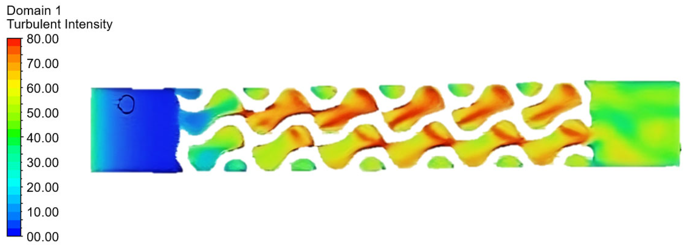
Furthermore, it is interesting to consider the turbulence intensity ratio (TI). It is a useful indicator to estimate the fluid regime of the coolant, it usually ranges in the interval TI ∈ [0–40]% where the lowest values are related to the laminar motion, while the highest ones are related to the turbulent regime. In heat exchangers, turbulent motion is very useful because it significantly increases the heat exchanged on a given area. As shown in
Figure 10, the gyroid lattice exhibits turbulent motion when water is used (average TI ≈ 20%); in contrast, oil is too viscous and the motion is still laminar when it is used (average TI ≈ 0%). Values higher than 50% should not be considered, since they are the result of the intricate geometry of the lattice and the kinematic calculation of the TI.
4. Study of Heat Exchange in Solid Lattice
For the considered case, the heat flux is exchanged between the outer cylindrical wall of the tube and the coolant fluid. For this set-up, the heat exchange capability is governed by two phenomena:
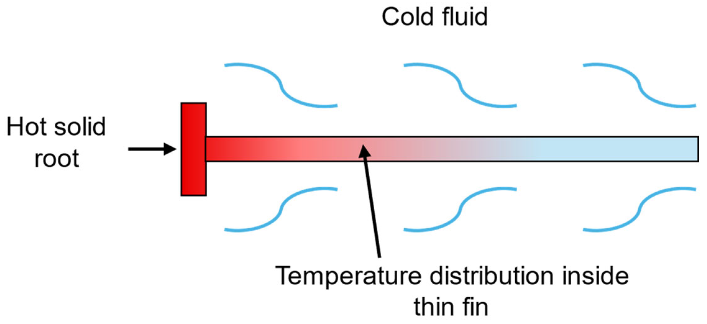
In this section, fluid convection is kept fixed and heat conduction in lattice walls is investigated. It is important to note that, according to the existing literature, the gyroid lattice can be used in two distinct ways. The most common application involves exchanging heat between two different fluids, where the two domains of the gyroid lattice remain well separated, and heat transfers between the two fluids through the thin walls of the lattice. On the other hand, the current study focuses on heat exchange between a hot outer wall and a coolant fluid that fills all the fluid domains of the gyroid lattice. In this scenario, the gyroid lattice functions similarly to a finned geometry, increasing the surface area between the fluid and solid domains. As studied by Tao et al. in [
35], thermal conductivity in solids becomes a key aspect for small fins because it affects temperature distribution along the fin itself, as shown in the scheme of
Figure 11. For a heat-dissipating fin, the longitudinal temperature distribution results from the thermal balance between conduction and convection. As a result, the average temperature is directly proportional to the conduction coefficient.
Therefore, the higher the average temperature of the fin, the greater the heat exchange.
In the literature, this problem is typically analyzed using an ideal reference case known as “isothermal fin”. In this scenario, the entire finned region is assumed to have the same temperature as the base material, maximizing convective heat transfer due to the large temperature difference between the cold fluid and the hot fin surface. However, in real-world conditions, the temperature distribution in the fin is heavily influenced by the material thermal conductivity. Materials with higher thermal conductivity, such as copper or aluminum, increase the average temperature of the fin, enhancing heat transfer efficiency. The fin conduction efficiency is defined as the ratio between the actual heat flux and the maximum possible heat flux in the isothermal fin case.
To apply this concept to a gyroid lattice structure, dedicated numerical simulations were conducted. The solid domain is now added to the fluid dynamic analysis. A coarser mesh is used to solve the heat conduction equation inside the solid material. The case of interest involves a sheet-type gyroid lattice with relative density 35% and a flow rate of 6 L/min, considering both ISOVG68 oil and water as working fluids. For each fluid, the flow conditions remain constant, while the thermal properties of the solid material vary. The relent thermal properties of the materials are reported in
Table 3.
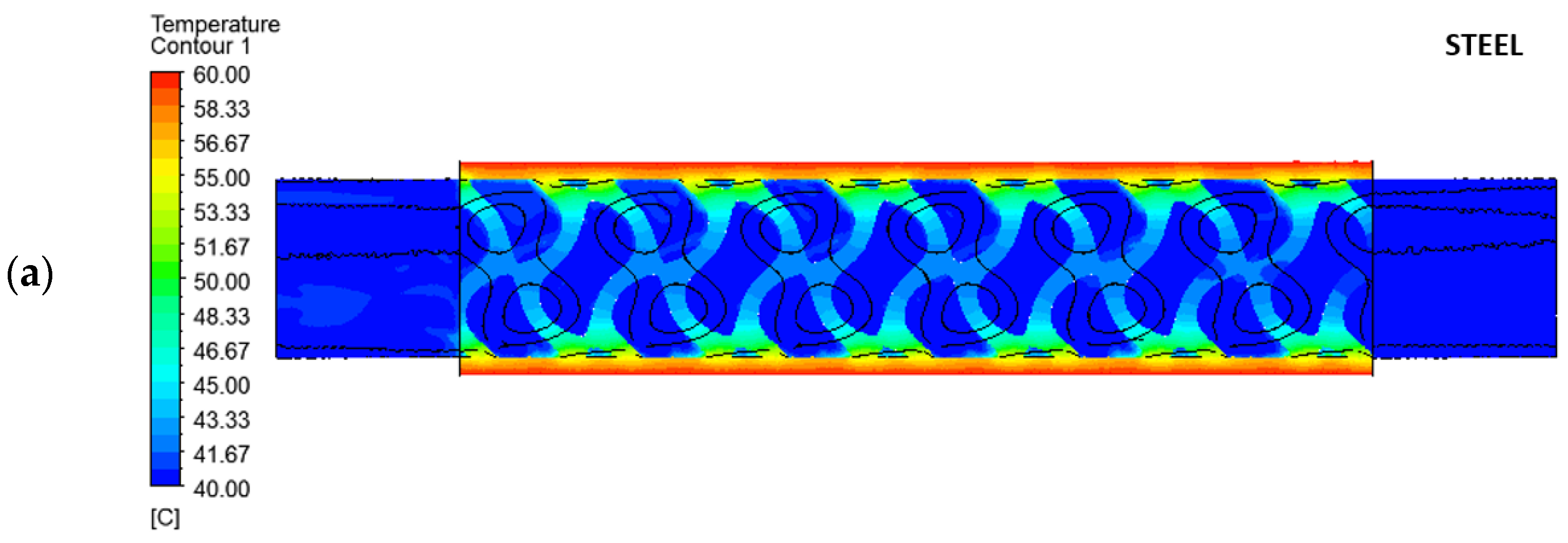
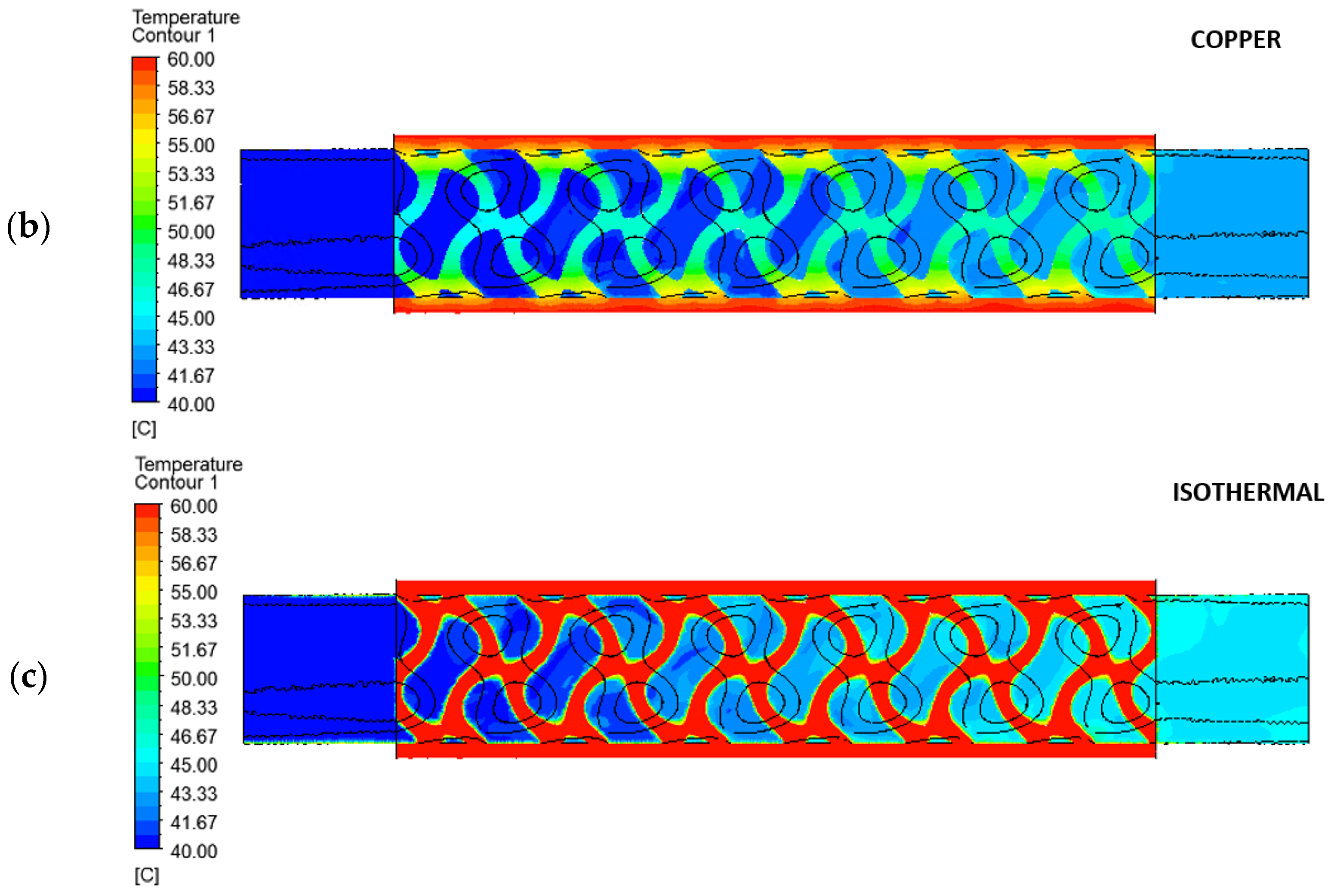
Three scenarios are analyzed: in the first, the solid domain is maintained at a constant temperature equal to that of the hot outer surface, simulating an ideal isothermal fin. In the other two cases, the material of the solid domain is either copper or steel. For the last cases, the temperature at the outer surface is fixed, but the temperature distribution within the solid domain is determined by the balance of heat transfer. Consequently, the heat exchange will be lower.
By looking at the results in
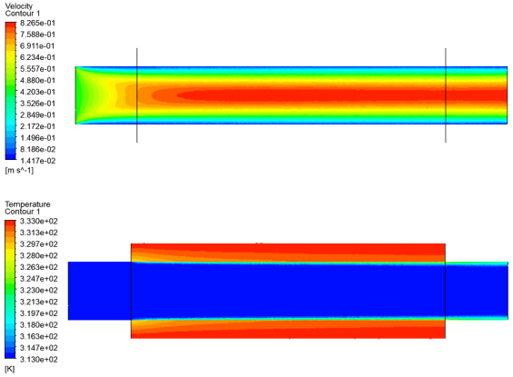
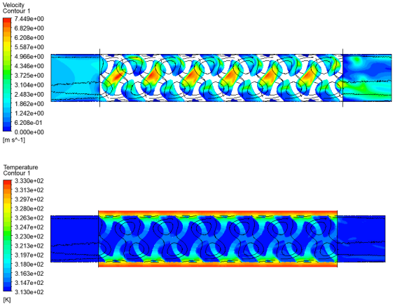
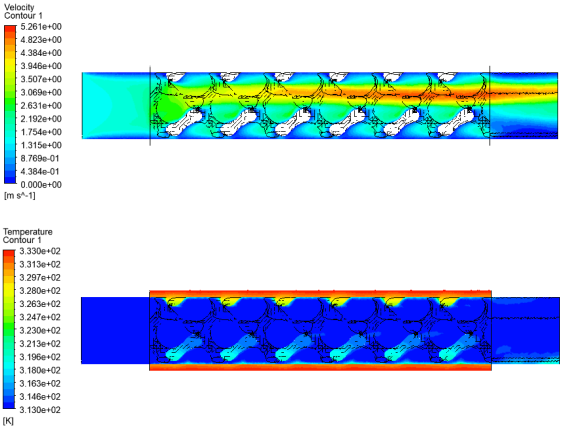
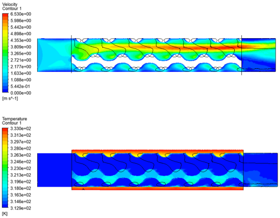
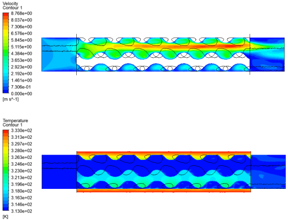
Table 4, it is important to assess the efficiency gain when changing the solid material relative to the ideal condition. The ideal isothermal case, by definition, always exhibits maximum efficiency. Notably, the efficiency difference between stainless steel and pure copper is approximately 43% for both oil and water cases. This consistent difference is due to the thermal resistance imposed by conduction in the solid material; copper is the favorable solution, even though more expensive. When looking at the coolant fluid, water is favorable with respect to oil. Although water exhibits lower heat exchange efficiency, which might seem counterintuitive, this is correct and can be explained by the increase in absolute heat exchange values. In other words, when water is used, lower efficiency means that the material choice for the solid domain becomes a bottleneck in heat exchange and it significantly reduces the overall exchanged heat. As a result of this analysis, copper is deemed the favorable choice, particularly when water is used as the coolant, resulting in higher heat exchange. The temperature fields computed for these calculations are shown in
Figure 12, with a gyroid lattice, sheet type, relative density 35% and water flow rate of 6 L/min.
5. Manufacturing of Samples and Set-Up of Experimental Campaign
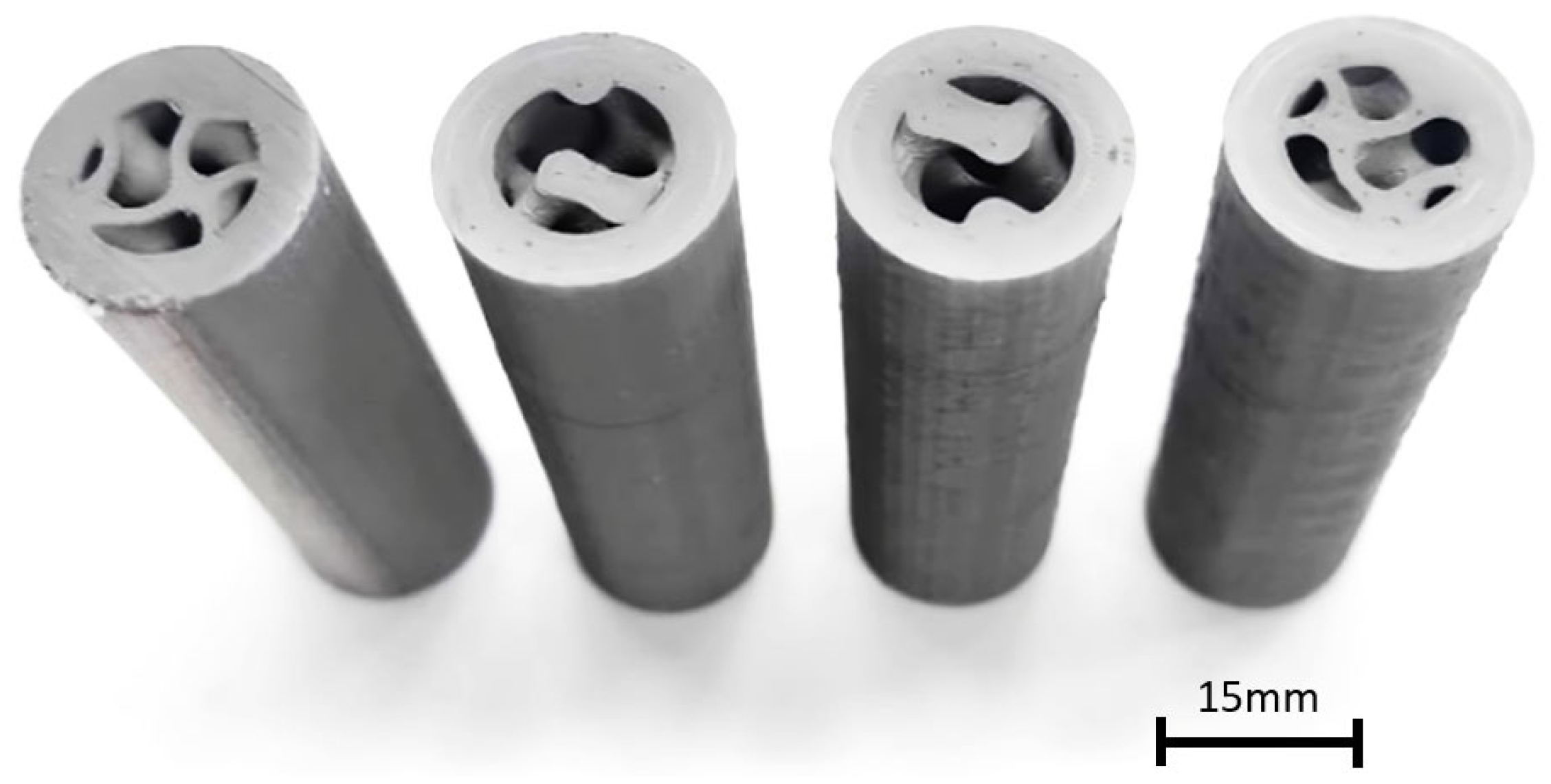
In order to validate the numerical results, a complementary experimental campaign was performed to reproduce the results of the simulations. First of all, the samples were successfully printed with bound metal deposition technology (
Figure 13), which consists of a material extrusion technique (MEX), in AISI-316L stainless steel [
36,
37,
38]. The most important advantages of this technology are the ease of use and the absence of loose metal powder, which could be difficult to flush away from the internal cavities. Examples of the resulting tubes are shown in
Figure 13. Gyroids have been proved to be printable with great accuracy, without the need of any internal supports.
After visual inspection, no evident geometrical defects and dimension errors were present.
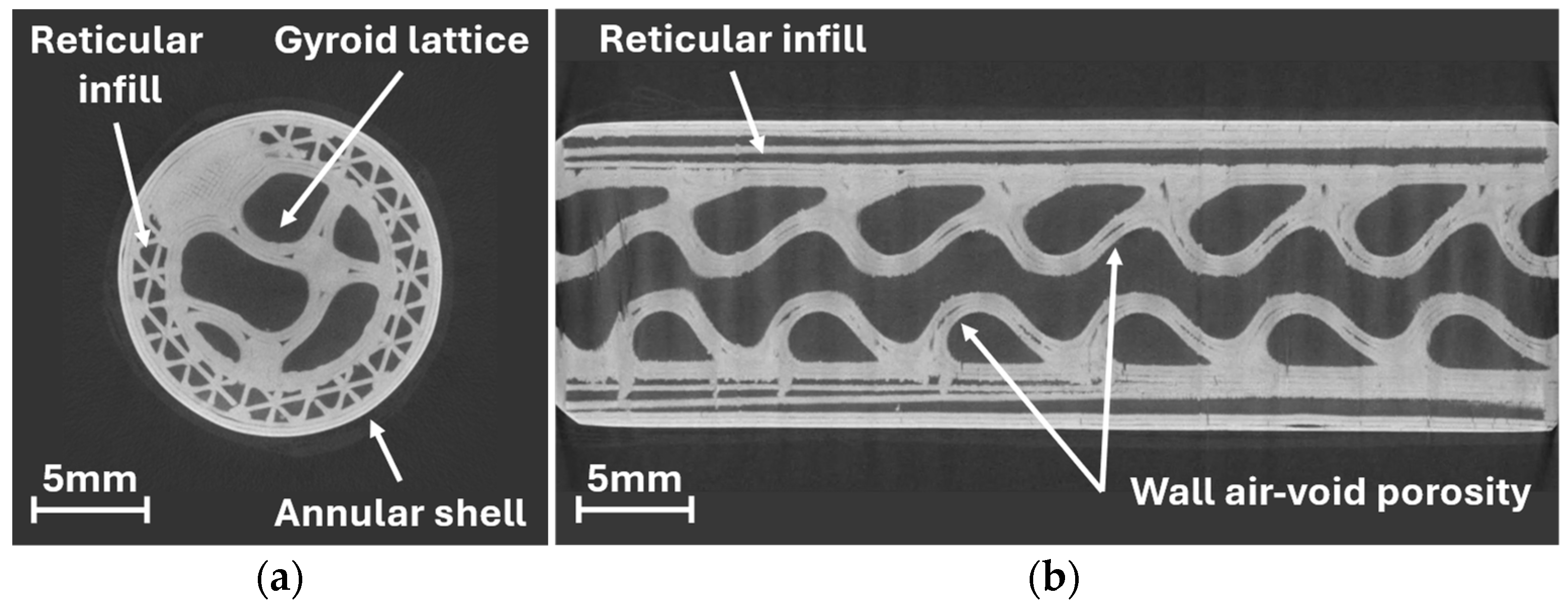
CT scanning was conducted on one tube filled with a sheet-type gyroid lattice of 35% as shown in
Figure 14a,b, to verify the consistency in the gyroid filling. A high-resolution microfocus CT system (300 kV Baker Hughes GE Phoenix V|tome|x) was employed for CT scans, featuring a microfocus X-ray. Equipped with a high-efficiency digital detector (e.g., flat-panel detector), the system employs advanced filtered back-projection algorithms for 3D image reconstruction. The adopted voxel resolution for the scan was 15 μm. The full video of the CT scan analysis is available in the
Supplementary Materials.
By looking at the results, the internal geometry appears correctly printed; no relevant defects are present, and no wall collapse is visible. Only localized and small air void porosity is noticed inside the gyroid walls, as a consequence of the 3D printing extrusion path adopted. Generally speaking, the scans confirm the successful printing of the components. Moreover, it is possible to notice the reticular structure (i.e., the infill) used inside the wall of the cylindrical annular shell.
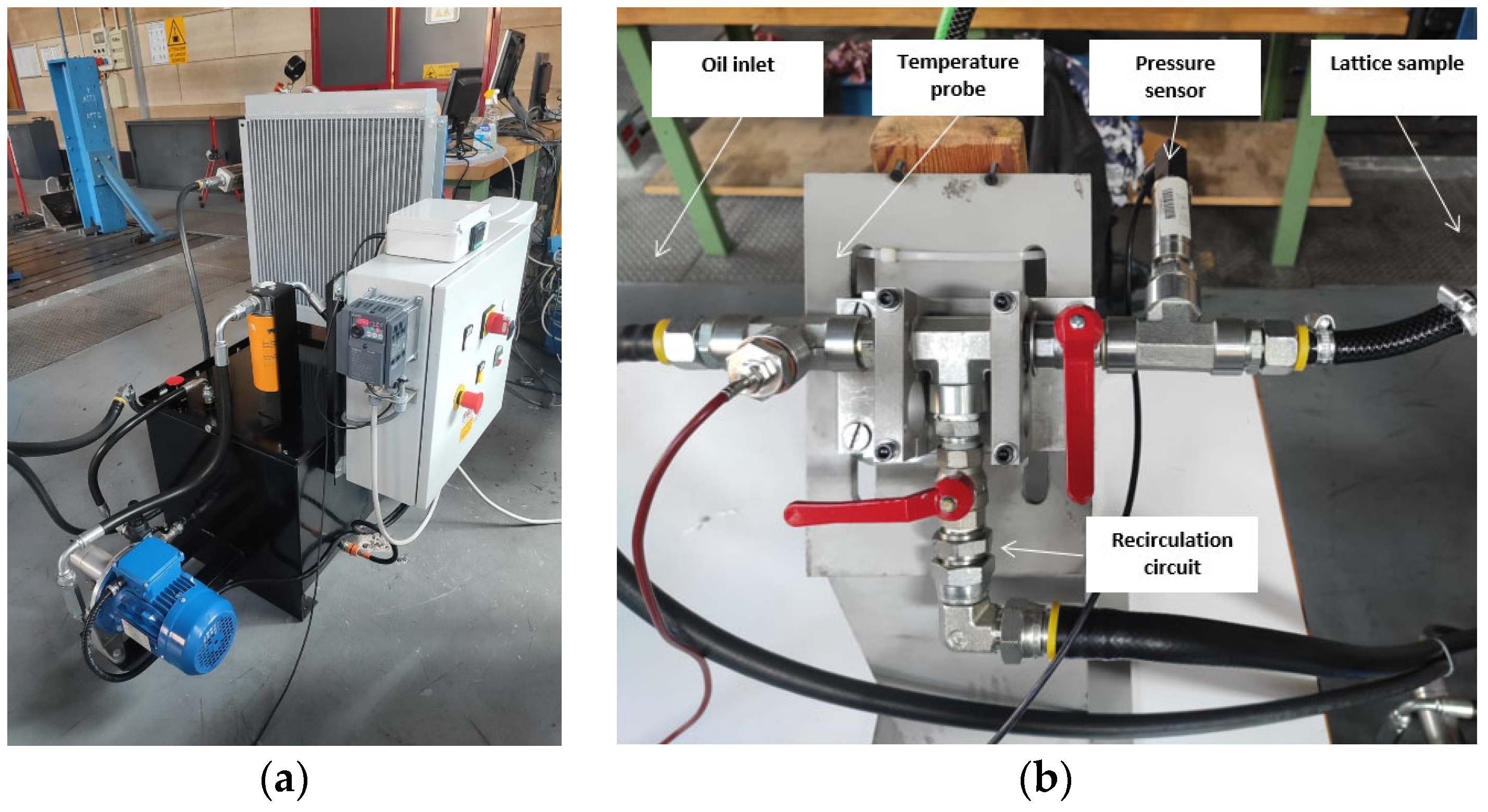
Subsequently, printed lattice samples were tested on a dedicated flushing circuit, as shown in
Figure 15a,b. The test bench is able to measure the pressure drop across the lattice sample. The type of coolant can be changed (oil or water), and the temperature and the flow rate of the coolant can be measured and adjusted. When oil is used, it is important to control the coolant temperature in order to guarantee the same viscosity used in simulations. The set-up is composed of an external pumping unit for the coolant with a temperature controller and a measuring apparatus. The temperature controller guarantees thermal steady-state conditions for the cooling fluid. The recirculation circuit is used before the measuring phase to easily reach a steady-state thermal condition. The coolant temperature and pressure drop across the sample are measured by probes, while the flow rate is calculated by weighing on a digital scale a certain quantity of coolant and the time needed to flow. Pressure measurements are performed for each coolant (oil/water) by adjusting the flow rate (1–6 L/min). Each measurement is repeated five times for robustness. The main limitation of the apparatus is its inability to measure heat exchange due to technical constraints. The main challenge lies in accurately controlling the outer wall temperature of the tube, which is critical for reliable heat transfer measurements. This typically requires an isothermal, temperature-controlled chamber. However, such a system is usually expensive and complex.
6. Experimental Results and Model Validation for Pressure Drop
Experimental pressure data are analyzed in this section. Pressure curves as a function of coolant flow rate are calculated for each sample and coolant type, as illustrated in
Figure 16a. The experimental data are accurately interpolated using a second-order polynomial, with a high correlation coefficient of 99.7%, confirming the absence of significant disturbance effects during the experiments. The choice of a second-order polynomial is based on the Bernoulli equation and is not linked to the numerical analysis.
Regarding the uncertainty analysis for the pressure curves, the uncertainty in flow rate is ±0.3%, while the uncertainty in pressure is ±0.1%. This procedure is applied to all tubes, and the resulting interpolated curves for oil are shown in
Figure 16b.
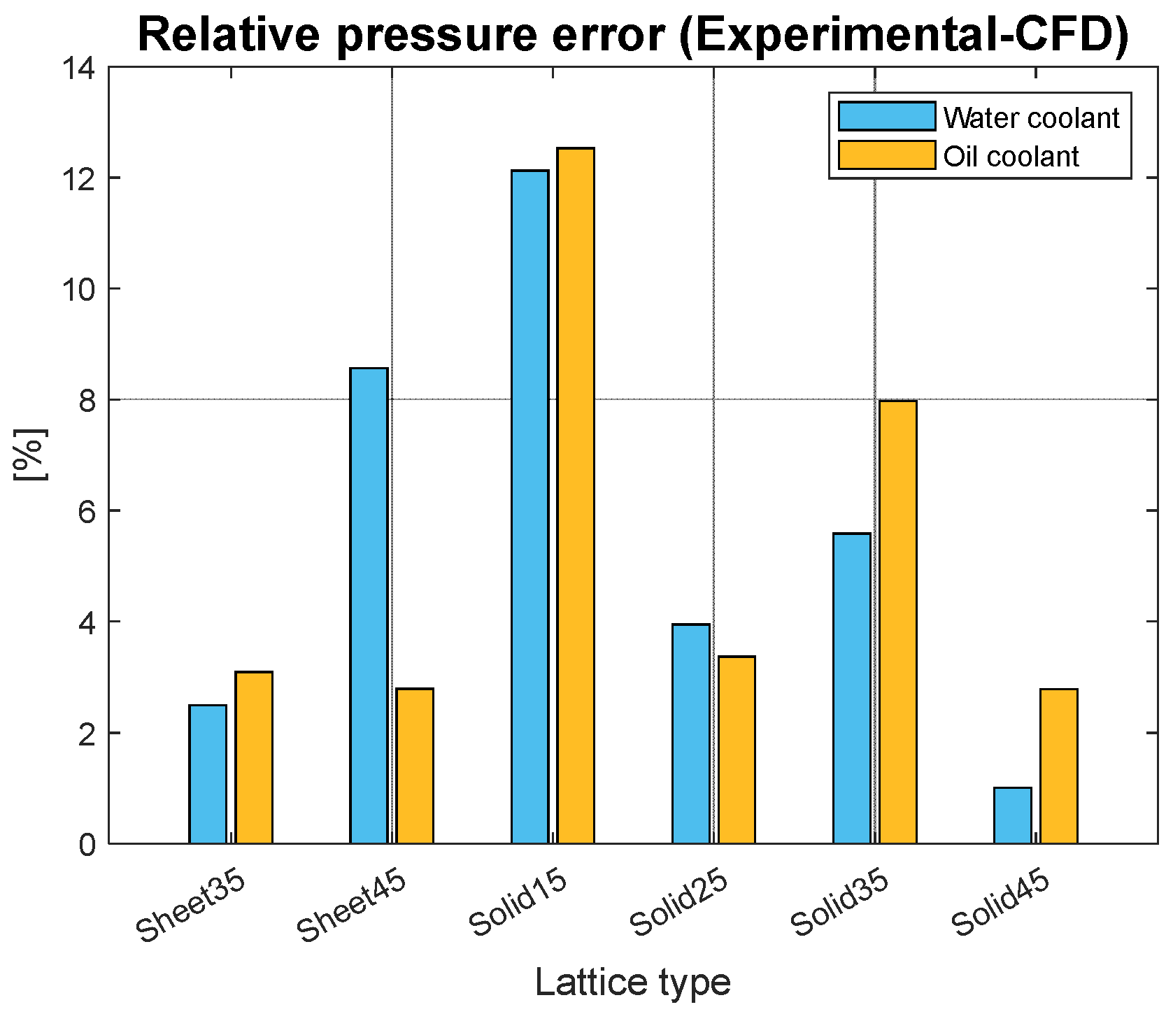
The experimental flushing was useful for validating the numerical model. The comparison between the experimental and the numerical data on the pressure drop is reported in
Figure 17. The difference is expressed as the average relative error on the pressure drop, for each lattice sample. The following equation was used to define the relative difference in the pressure drop:
where
err is the percentual difference between the measurements,
is the experimental measurement of the pressure drop, and
is the numerical estimation of the pressure drop. For the different flow rates and lattice samples, the average error is around 5% and is considered satisfactory, given the complexity of the studied geometry. The highest error occurs for the solid lattice with relative density of 15%, probably because of some internal printing defects. The developed model is proved to be accurate for the estimation of the pressure drop. Conversely, no validation can be performed on heat exchange values due to experimental set-up difficulties, as discussed in
Section 5.
7. Discussion and Conclusions
The proposed research develops a numerical model for estimating the internal fluid dynamics in gyroid lattices. The model results align well with the experimental findings, providing confidence in the approach. Several key insights emerge from the study.
Firstly, as shown by the numerical results on pressure drop in
Figure 8a, the gyroid lattice exhibits significantly higher backpressure compared to a plain tube. This outcome is expected due to the more complex fluid pathways within the lattice. In heat exchange applications, pumping power is typically several orders of magnitude lower than the heat exchanged, which often justifies neglecting it. However, it is common practice to set a maximum allowable backpressure that suits the specific application. In industrial contexts, pressures below 10 bars are generally manageable.
Regarding heat exchange performance (
Figure 8b), the gyroid lattice significantly enhances heat transfer, achieving up to five times the baseline level. This result is crucial as it confirms findings from the existing literature. Additionally, it is noteworthy that the sheet lattice exhibits slightly higher heat transfer, approximately 20% more than the solid type, likely due to differences in the effective heat transfer area.
To effectively compare the performance of different lattices, it is essential to consider both the heat exchange and pressure drop contributions, using the overall enhancement factor (
Figure 9b). This metric clearly indicates the heat exchange efficiency, with solid lattices emerging as the more favorable option. Ultimately, the choice of lattice design should balance the required heat exchange with acceptable backpressure levels, depending on the specific application. For the case considered (solid-to-fluid heat exchange), conduction in the solid material is a critical factor and should be carefully considered in the final design. Highly conductive materials, such as copper or aluminum, are highly recommended when water coolant is used.
This experimental work has been particularly valuable in validating the proposed geometries. Additive manufacturing has demonstrated its capability to successfully produce the samples, with no significant defects observed, and the geometry showing excellent self-sustainability, as confirmed by the CT scan.
In conclusion, this research advances the current understanding of the heat transfer capabilities of gyroid lattices. The complex lattice geometry effectively promotes and sustains fluid turbulence, especially when water is used, leading to a substantial increase in heat exchange. A comparative analysis was conducted by varying key lattice design parameters, and the resulting pressure drop data were validated through a dedicated experimental campaign, showing good agreement. Additionally, an interesting industrial application of the gyroid lattice is detailed by the same author in [
19]. A promising area for future work is the optimization of the external shape of the heat exchanger, where developing innovative topologies could further enhance cooling capabilities while reducing coolant backpressure.


