Article

Meshing Characteristic Analysis of CBR Reducer Considering Tooth Modification and Manufacturing Error

by
Xiaoxiao Sun
1,2,*,
Zhihao Qian
1,
Yaochen Xu
1 and
Jiacai Huang
2
1
School of Mechanical Engineering, Nanjing Institute of Technology, 1 Hongjing Avenue, Nanjing 211167, China
2
Jiangsu Bionic Control Technology and Equipment Engineering Research Center, 1 Hongjing Avenue, Nanjing 211167, China
*
Author to whom correspondence should be addressed.
Machines 2024, 12(12), 915; https://doi.org/10.3390/machines12120915
Submission received: 13 October 2024 / Revised: 9 December 2024 / Accepted: 10 December 2024 / Published: 13 December 2024
(This article belongs to the Section Advanced Manufacturing)

Abstract

The China Bearing Reducer (CBR) is a single-stage cycloid reducer with a compact structure, primarily used in high-precision fields such as robotic joints and Computer Numerical Control (CNC) machine tool turntables, where strict requirements for transmission accuracy are necessary. Tooth modification and manufacturing errors in the cycloid gear are two important factors affecting the transmission accuracy of CBRs. In this paper, the transmission performance of the CBR is studied using a new tooth modification method that considers manufacturing errors. Firstly, the structure of the CBR is introduced, and a new method known as Variable Isometric Sectional Profile Modification (VISPM) is proposed. Secondly, the Tooth Contact Analysis (TCA) model is constructed using the VISPM method, and a method for reconstructing the tooth profile with cycloid tooth profile error based on B-spline curve fitting is proposed. The TCA is carried out with both VISPM and tooth profile error. The influence of the modification parameters on meshing characteristics, such as contact force, contact stress, contact deformation, and transmission error, is analyzed. Thirdly, the optimization of the modification parameters is conducted using Particle Swarm Optimization (PSO) to determine the optimal VISPM and isometric and offset modification (IOM) parameter values. The results indicate that the VSIPM method is superior to the IOM method in enhancing meshing characteristics. A physical prototype of the CBR25 is manufactured using the optimized VISPM and IOM, and the transmission error is tested on an experimental platform. The test results demonstrate that the ETCA method is corrected for cycloid drive analysis.

1. Introduction

The cycloid pinwheel drive offers advantages such as a high speed ratio, high precision, high stiffness, and a compact structure. It has been widely used in fields such as robotics, CNC turntables, and precision medical instruments, aviation, space, military, automotive, and other industries. Aviation technology benefits from these gears in helicopter transmissions and aircraft propulsion systems, where their dependability and efficiency are critical. The space sector utilizes cycloidal gears in the deployment of satellites and in the construction of robotic arms, where precision and endurance are essential. Military applications include their use in armored vehicles and weaponry, where the gears’ strength and compactness offer significant advantages. In the automotive industry, cycloidal gears are utilized in gearboxes and differentials, enhancing the performance and lifespan of vehicles. Currently, most robot joint reducers utilize cycloidal pinwheel transmissions, which are one of the three core components of industrial robots. The transmission accuracy, transmission efficiency, and service life of the reducer directly determine the positioning accuracy and service life of the robot. It is an indispensable component for the development of the robotics field and holds great significance for the advancement of high-precision equipment and the intelligent manufacturing industry.
To ensure transmission accuracy and lubrication conditions, scholars have proposed constructing the appropriate tooth clearance by modifying the profile of the standard cycloid gear to compensate for manufacturing errors. The modification methods have evolved from traditional isometric and displacement modifications [1,2,3,4,5,6,7,8,9] to parabolic modifications [10] and key-point spline curve-fitting modifications [11]. Yang and Blanche [1,2] discussed the geometric principles of cycloid transmission, derived the cycloid tooth profile equation from the geometric motion laws, and analyzed the impact of cycloid gear machining errors on the backlash and transmission ratio fluctuations of the reducer. They then comprehensively analyzed the calculation method of cycloid needle gear transmission backlash and transmission error by using a computer-aided analysis method and analyzed the influence of error and needle gear radius modification on backlash and the transmission error. Liyong Zhang et al. [3] investigated the impact of isometric and shifting modifications of the cycloid gear on the transmission backlash of cycloid drives, taking into account the characteristics of multi-tooth engagement and the profile equation of the modified cycloid gear. They established a multi-objective optimization mathematical model for cycloid gear modification parameters, aimed at ensuring both the backlash and the strength of the reducer. Xueping Song et al. [4] introduced a method for multi-objective optimization that modifies the cycloid drive, considering its maximum transmission error, based on compound modification techniques. Wan sung Lin et al. [5] utilized TCA to study a two-stage cycloidal pinwheel reducer with equal distance plus displacement modification, and established the matrix form of the modified tooth profile equation of the two-stage cycloidal wheel and the matrix form of the unit normal equation of the corresponding tooth profile under the same coordinate system, respectively. Based on the conjugate meshing theory, non-linear TCA equations were established, and the transmission error was analyzed. Subsequently, Ken Shin Lin et al. [12] of the research group applied the TCA method to analyze the transmission error of a modified cycloid needle wheel, proposed a tooth profile discretization method to analyze the contact characteristics of a cycloid needle tooth surface, and compared the calculation efficiency and accuracy with traditional TCA. Yu Hong Liu et al. [6] studied the tooth surface meshing problem of cycloidal pin gear reducer with the non-Hertz elastic contact problem, and proposed an analysis method of the non-Hertz flexibility matrix to study the influence of different modification quantities on the tooth surface load distribution. Xiao xiao Sun et al. [7,10] established the load tooth contact analysis (LTCA) model for a cycloid drive with isometric and offset modification, proposed the LTCA method based on a discrete point tooth profile, and compared the influence of several groups of different isometric and offset modification methods on transmission error and contact force. Then, the advantages of the parabolic modification method are studied, a mathematical model of the parabolic modification tooth profile is established, and the parabolic modification coefficient and modification amount are optimized by the LTCA. Suzhen Wu et al. [9] introduced a novel approach for optimizing the modification amounts of tooth profiles in cycloidal reducers, focusing on the refinement of transmission error and transmission ratio fluctuation. W. Sensinger [13,14] proposed a unified equation for optimizing the design of cycloid gears, identified the sources of errors in cycloidal transmissions, and discussed the influence of each error on the transmission ratio, backlash, and running stability, also deriving equations for stress, efficiency, and the moment of inertia. Zhong Yi Ren et al. [11] proposed a method to modify the cycloid tooth profile by adjusting the positions of five key points on the cycloid tooth profile, deduced the tooth profile calculation formula of the new modification method, and compared it with the contact force and contact stress of the unmodified cycloid pinwheel drive to verify that the new modification method was better than the transmission modification. Yinghui Zhang et al. [15] proposed a multi-objective optimization design method that considers both the modification parameters and macro-parameters of the cycloid gear. Song Gao et al. [16] introduced a piecewise modification technique that employs a profile altered by a rotated angle method for the working segment. Additionally, both the dedendum and addendum segments utilize spline interpolation curves, ensuring the presence of radial gaps and achieving a smooth transition between the working and non-working segments by using these gaps as boundary conditions.
In the above modification method, researchers control the gap distribution from the tooth root to the tooth tip by modifying the standard tooth profile so as to improve the transmission accuracy and load capacity, but did not consider the influence of error on the gap. Therefore, some researchers analyzed the cycloid drive with tooth modification by considering manufacturing error. Linh Tran et al. [17] analyzed the kinematics of cycloidal transmission and studied the lost motion of cycloidal transmission with machining error by the iterative finite element analysis method. Xuan Li et al. [8] put forward an analysis model of the cycloidal reducer for TCA and LTCA, and studied the influence of radial and roller hole clearance and eccentricity error on key design factors, such as contact stress, transmission error, transmission ratio, and load on bearing. Tianxing Li et al. [18] studied the cycloid gear tooth modification of the RV reducer considering pitch error and profile error. The research results show that the pitch error had the greatest influence on the transmission error of RV reducers. Junzheng Wang and Hongzhan Lv [19] introduced a cycloidal gear machining error compensation and modification model, which was formulated on the basis of the Monte Carlo simulation method. This model offers a novel theoretical approach for the compensation of cycloidal gear machining errors. Antoniak, P. et al. [20] developed a model to describe the backlash distribution in the output mechanisms of cycloidal gears with serially arranged rollers, considering the machining deviations of their components. Considering the influence of assembly error on the output structure of a cycloidal pinwheel transmission device, Lixin Xu [21] established a dynamic model to predict the pin number of the output mechanism engaging in transmitting load and analyzed the influence law of assembly clearance on the contact pin.
In the above research, the researchers studied the influence of machining error and assembly error on transmission accuracy. However, they did not comprehensively consider the coupling effect of errors and modification parameters on the transmission accuracy, and how much the modification values should be suitable for the error values to achieve optimal transmission performance. In this article, we present a new VISPM method for the cycloid gear of a CBR. By analyzing the contact pressure angle of the cycloid drive, the tooth profiles of the working section and the non-working section are divided. For different sections, the clearance between the working section and the non-working section was accurately controlled by dynamically changing the pin radius of the tooth profile equation. The VISPM method can significantly increase the load capacity and improve the transmission efficiency of the cycloid drive.
The remainder of this paper is organized as follows: Section 2 introduces the VISPM modeling of a CBR, including a brief introduction of the CBR structure, cycloid tooth profile equation, and its isometric modification tooth profile equation. On this basis, the VISPM method is proposed. Section 3 introduces TCA modeling considering both the VISPM and manufacturing error of cycloid gear, and the cycloid tooth profile with tooth profile error is reconstructed. Section 4 introduces the optimization of transmission error by the VISPM of the CBR based on PSO. Section 5 introduces the test methods and equipment for transmission error. In the last section, the main conclusions from this study are presented.

2. Modeling of VISPM of CBR

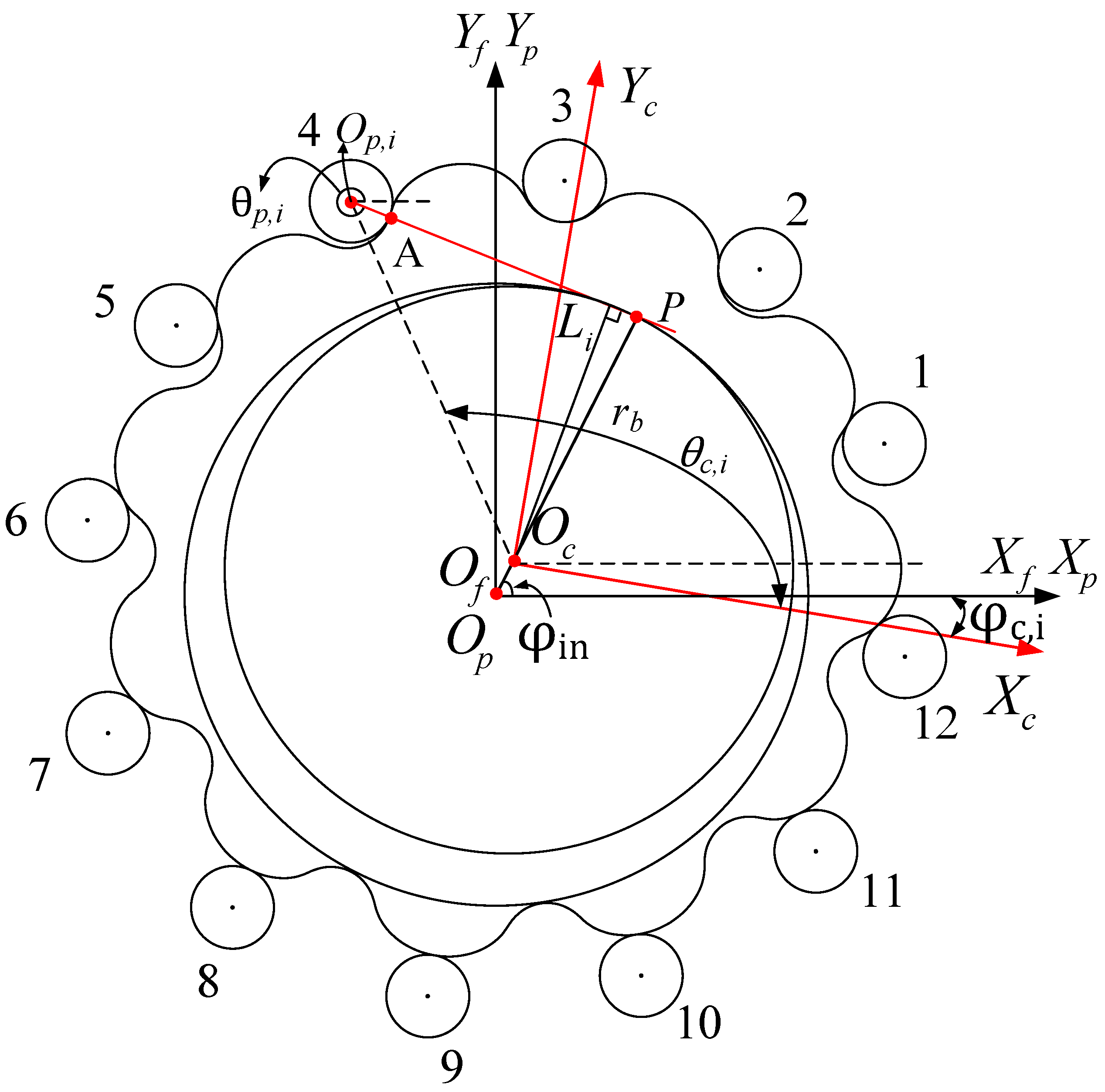
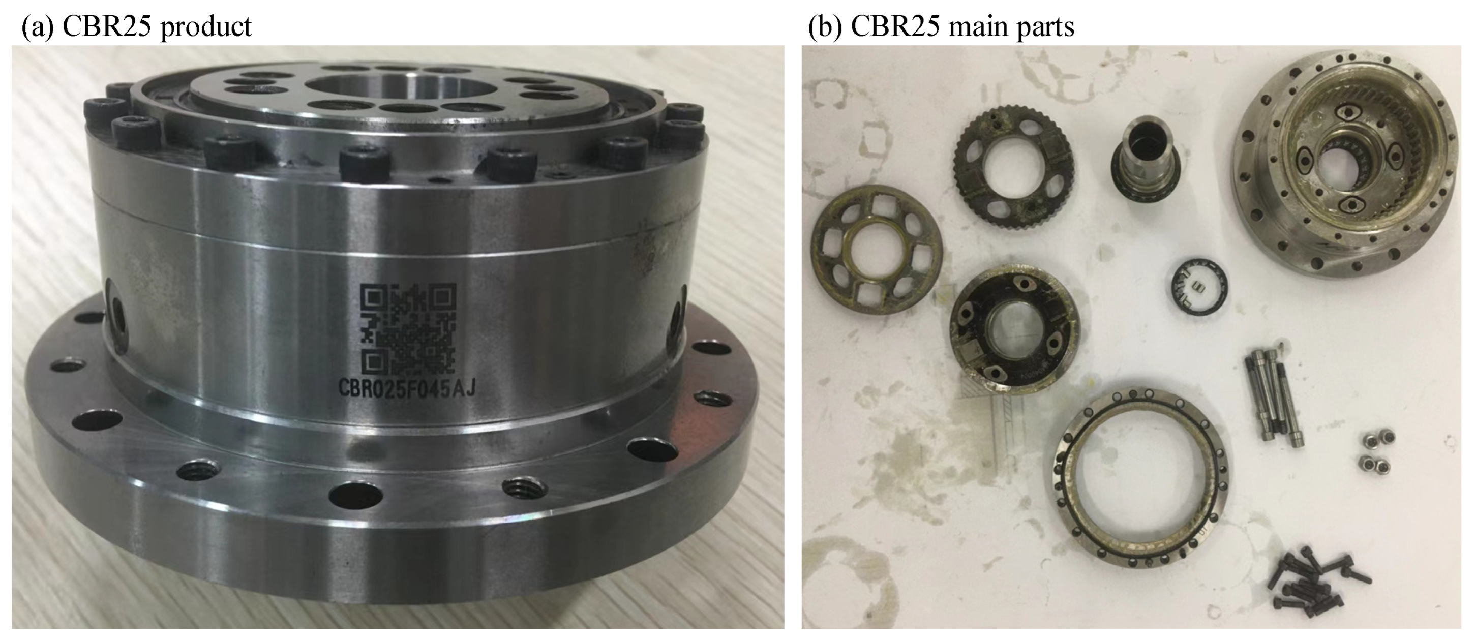
2.1. Structure of CBR

A CBR is a one-stage cycloidal pinwheel reducer with a symmetrical structure. The structure, which was modeled by SolidWorks, is shown in Figure 1. For a detailed introduction to the structure, see [22]. All parts of CBRs are separated by cylindrical rollers, which make it a structure of radial and axial output bearing. And the high-speed element of the reducer is directly supported by the roller bearing inside the reducer. This design allows the input bearing to bear the radial load from the outside, and no additional bearing is required between the reducer and the driving element. The cycloid gear of a CBR is a key component to ensure its transmission performance. Its processing precision is difficult to ensure and there will be manufacturing errors. In order to ensure its transmission performance, this paper proposes a new modification strategy to improve the transmission accuracy of CBRs.

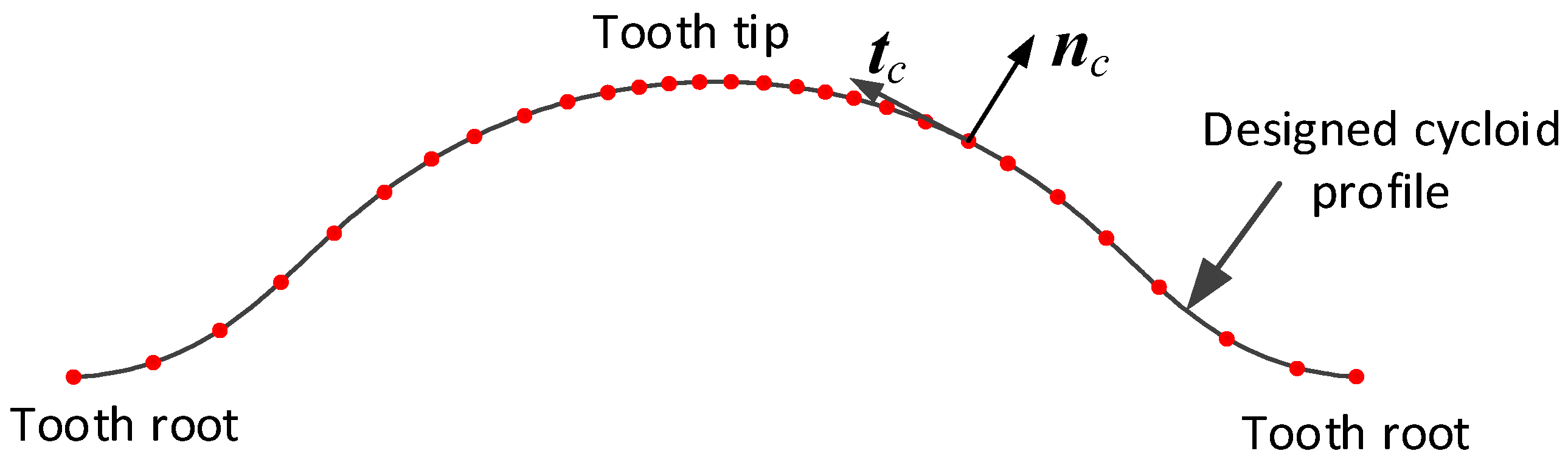
2.2. Tooth Profile Equation of Cycloid Gear with VISPM

Scholars have conducted a lot of research on the establishment of the cycloid tooth profile equation. To sum up, there are two widely used establishment methods, which are based on the geometry method and gear meshing principle. Here, the standard tooth profile equation (STPE) of a cycloid gear according to the gear meshing principle is directly given in Equation (1). For the detailed process, see [22].
r c = R p cos φ p z c + R r p cos a t a n 2 K 1 sin φ p , 1 K 1 cos φ p φ p z c a · c o s ( φ p · i H ) R p sin φ p z c + R r p sin a t a n 2 K 1 sin φ p , 1 K 1 cos φ p φ p z c + a · s i n ( φ p · i H ) 0 1
where R p is the radius of the roller gear and R r p is the radius of the roller, φ p is the rotation angle of roller gear, a is the eccentricity of the input crank shaft, and K 1 is the short width coefficient, K 1 = a z p / R p .
The pin radius R r p of the STPE is taken as the tooth profile modification parameter. A minor constant amount R r p in the STEP is added to R r p , which refers to isometric modification. The isometric modification tooth profile equation (IMTPE) can be written as Equation (2). When isometric modification is used alone, the modification amount R r p must be positive to obtain a modified tooth profile that is smaller than the standard tooth profile.
r c 1 = R p cos φ p z c + ( R r p + R r p ) cos β φ p z c a c o s ( φ p · i H ) R p cos φ p z c sin φ p z c + ( R r p + R r p ) sin β φ p z c + a sin ( φ p · i H ) 0 1
where β = a t a n 2 K 1 sin φ p , 1 K 1 cos φ p , and R r p > 0 .
The isometric and offset modifications (IOMs) [7] are achieved by adding a minor constant amount R r p to the pin radius R r p and a minor constant amount R p to the pin position R p to modify the cycloid tooth profile. So, an appropriate tooth profile of the cycloid gear is obtained by adjusting the two constant values. Although the IOM method can obtain an appropriate tooth profile, it cannot flexibly adjust the cycloid tooth profile. Parabola modification (PM) [10] can set the working contact sections of cycloid tooth profiles, but it is not flexible for setting the clearance of the whole tooth profile, which can only be set in the form of a single parabola. The VISPM method can flexibly set the clearance between the cycloid gear and pin gear according to the piecewise situation. The clearance distribution law is not limited to a single parabola, but can follow the combined multi-segment linear or nonlinear distribution law. The tooth profile equation of the VISPM method is analogous to that of isometric modification. Changing R r p into a sectional function V R r p , it can be written as
r c 2 = R p cos φ p z c + ( R r p + V R r p ) cos β φ p z c a · c o s ( φ p · i H ) R p sin φ p z c + ( R r p + V R r p ) sin β φ p z c + a · s i n ( φ p · i H ) 0 1
where V R r p is a piecewise function.
To improve the loading capacity, the segmentation is based on the pressure angle α of the tooth profile. Firstly, the pressure angle from the tooth tip to the tooth root should be calculated, as shown in Figure 2a. Then, the tooth profile with a small pressure angle close to the reference point is selected as the working section, and the tooth profile with a large pressure angle close to the tooth tip and tooth root is selected as the non-working section. The modification amount of the working section is small, while the non-working section is large. So, the CBR reducer can be easily assembled and has good lubrication. Generally, the cycloid tooth profile from the tooth top to tooth root is divided into four parts: AB, BC, CD, and DE. As shown in Figure 2b, point A is the tooth root, point E is the tooth tip, and the position of points B, C, and D is selected according to the pressure angle of the cycloid tooth profile. The piecewise function value of each tooth profile varies with the pressure angle α . If the modification amount of AB and DE sections is linear, and BC and CD is constant, as shown in Figure 2c, V R r p can be expressed as:
V R r p = b 1 φ p + c 1   A B , c 2 ( B C ) c 3 ( C D ) b 4 φ p + c 4   ( D E )
Taking the CBR25 as an example, the design parameters of cycloid gear are shown in Table 1. Given different piecewise functions, different modified tooth profiles can be obtained. Here, take point C as the theoretical contact point of the minimum pressure angle, which is φ p | C = 0.666 . The modification amount of AB and DE segments has a linear relationship with the pressure angle, and the modification amount of CB and CD segments also has a linear relationship with the pressure angle. Figure 3 shows the shape of a half-tooth profile with three different modification parameters (as shown in Table 2). It can be seen from the figures that the value of V R r p at different points determines the clearance, and the value of φ p at different points determines the working and non-working sections.

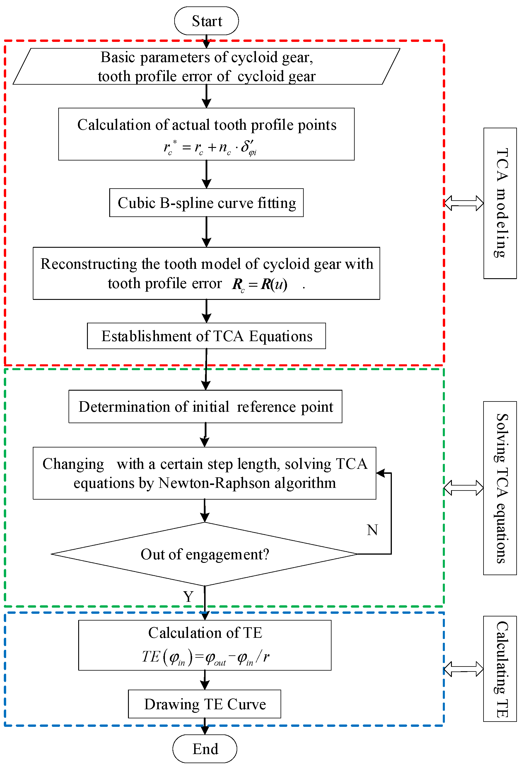
3. TCA Both Considering VISPM and Manufacturing Error

After tooth profile modification, the cycloid gear no longer has conjugate meshing with the pin teeth in theory. In order to analyze the meshing characteristics of the modified cycloid gear and the pin teeth and provide a reference for the optimal modification of the cycloid gear, it is necessary to analyze the TCA of the cycloid–pin gear pair. TCA is the calculation method for analyzing the meshing contact characteristics of a gear pair. The concept of TCA was introduced in the 1960s and was initially used as a research method in the study of spiral bevel and hypoid gears [23]. Researchers have applied it to the study of cycloid–pin wheel transmission [24,25,26,27], and it has become a very popular analysis method in recent years.
Manufacturing errors in cycloid gears include tooth pitch error, tooth profile error, gear ring diameter round runout error, cross-section comprehensive error, and tooth direction error. The tooth profile error is mainly studied here.

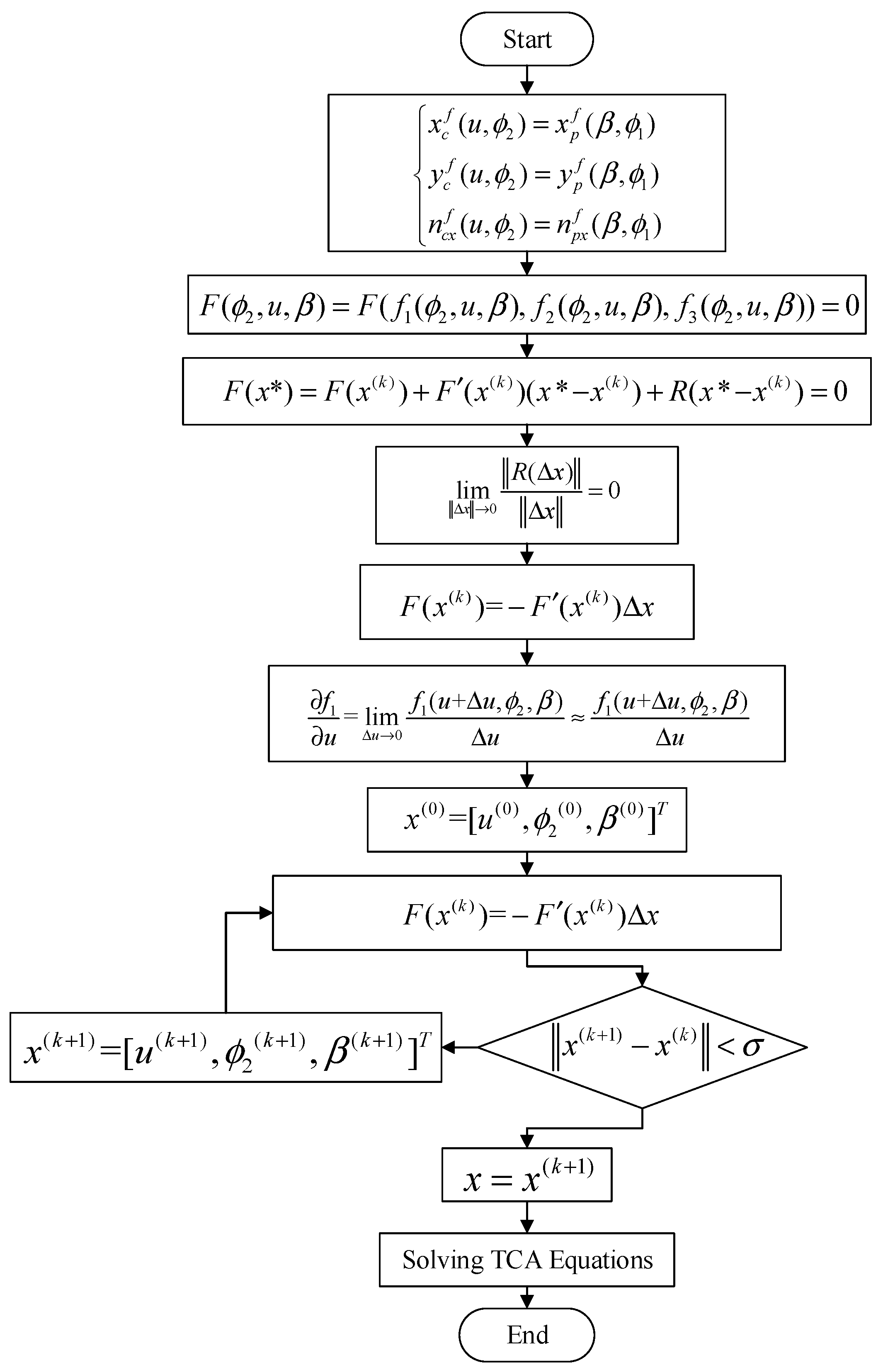
3.1. Modeling and Solving TCA and TE with VISPM

Figure 4 shows the coordinate system (CS) used in TCA. S f is the fixed coordinate system, O f is its origin, S p and S c are the conjoined CS of the pin gear and cycloid gear, respectively, and O p and O c are the origin of the corresponding CS. As the position of the case and the pins is fixed, the center of the case is set as the origin, and S p coincides with S f . For the convenience of analysis, the pin teeth are numbered counterclockwise, as shown in Figure 4. φ i n is the input crank angle, φ c , i is the required rotation angle of the cycloid gear when the i-th pin tooth comes into contact with the cycloid gear; θ p , i is the angle parameter of the contact point on the i-th pin tooth; and θ c , i is the angle parameter of the contact point on the cycloid gear when the i-th pin tooth contacts with the cycloid gear.
As the coordinate system S p and S f coincide, they do not need coordinate transformation. The expression of the contact point on the i-th pin in S f is can be written as
r f ( p , i ) ( θ p , i ) = r p ( p , i ) ( θ p , i ) = R p · sin i · β p + R r p · c o s ( θ p , i ) R p · cos i · β p + R r p · sin ( θ p , i ) 0 1
where β p is the angle between the two adjacent pins, β p = 2 π / z p .
Equation (5) is derived for θ p , i , cross-multiplied by the unit normal vector k in the XY plane, and then unitized to obtain the unit normal vector in S f for the contact point on the i-th point; it can be written as
n f p , i θ p , i = n p p , i ( θ p , i ) = d r p ( θ p , i )   ×   k d θ p , i d r p ( θ p , i )   ×   k d θ p , i
The expression of the contact point on the profile of VISPM in S c is shown in Equation (3). It needs to be transformed into S f in order to perform TCA. The coordinate transformation matrix from S c to S f can be expressed as
M f c = cos ( φ c , i ) sin ( φ c , i ) 0 a cos ( φ i n ) sin ( φ c , i ) 0 0 cos ( φ c , i ) 0 0 0 1 0 a sin ( φ i n ) 0 1
The unit normal vector of the cycloid gear profile in S f can be expressed by Equation (8)
n f c , i θ c , i = L f c n c c , i θ c , i
where L f c is the first 3 × 3 term submatrix of M f c .
According to the conjugate condition, the meshing point of two gears should satisfy the following equations
r f c , i θ c , i , φ i n , φ c , i = r f p , i θ p , i n f c , i θ c , i , φ i n , φ c , i = n f p , i θ p , i
where θ c , i is the cycloid parameter angle, φ i n is the input crank angle, φ c , i is the cycloid output angle, and θ p , i is the pin parameter angle. When φ i n is given, the other three parameters can be solved by Equation (9).
To solve the nonlinear equations, the initial value needs to be provided. The selection of the initial value is very important for the solution of the nonlinear equations, so the initial meshing point must be determined first. After modification, the relationship between the cycloid wheel and needle wheel is no longer conjugate, and the transmission ratio is no longer a fixed value. Because of the flexible adjustment advantage of VISPM, the cycloid gear and the pin gear can be controlled to come into contact first at the theoretical meshing point. Therefore, the theoretical meshing point can be used as the initial reference point for TCA equations.
As shown in Figure 4, the cycloid–pin gear pair is in the initial meshing state in S p , and the meshing point A (XA, YA) is the initial reference point. At this time, the common normal of the cycloid–pinwheel pair passes through the theoretical node P r b cos φ i n , r b sin φ i n , O p , i R p cos i · β p ,   R p sin i · β p is the center of the corresponding pin tooth, and r b is the pitch circle radius of the pin gear. According to the gear meshing law, the common normal line at the meshing point passes through the theoretical node P, so the initial value θ p , i 0 of the angle parameter of the contact point on the pin gear can be expressed as
θ p , i 0 = a t a n 2 r b sin φ i n R p sin i · β p , r b cos φ i n R p cos i · β p
Origin O f in S f can be expressed as ( acos φ i n ,   a sin ( φ i n ) ) in S c . The coordinate value of contact point A in S c can be obtained from O c O f + O f O p , i + O p , i A . Then, the initial value θ c , i 0 of the angle parameter of the contact point on the cycloid gear can be expressed as
θ c , i 0 = a t a n 2 R p sin i · β p + R r p sin θ p , i 0 a sin φ i n , R p cos i · β p + R r p cos θ p , i 0 a cos φ i n + φ c , i 0
In the state of contact point A, the initial value of the required rotation angle of the cycloid gear can be expressed as
φ c , i 0 = φ i n / z p
Given the input crank angle φ i n , the initial value of the reference point can be calculated by using Equations (10)–(12). Then the initial values obtained are brought into the TCA equations, and the corresponding θ c , i ,   φ c , i ,   θ p , i can be obtained. With the increase in the crank shaft input angle φ i n , the θ c , i ,   φ c , i ,   θ p , i value of the whole meshing process can be finally obtained.
The transmission error (TE) is the difference between the actual output angle and the theoretical output angle, which can be expressed as
T E ( φ i n ) = φ o u t φ i n / r
where, φ o u t = max ( φ c , i ) and r is the transmission ratio.
When the CBR reducer is running under load, the loaded transmission error (LTE) can be obtained by substituting the unloaded results into LTCA [7,10].

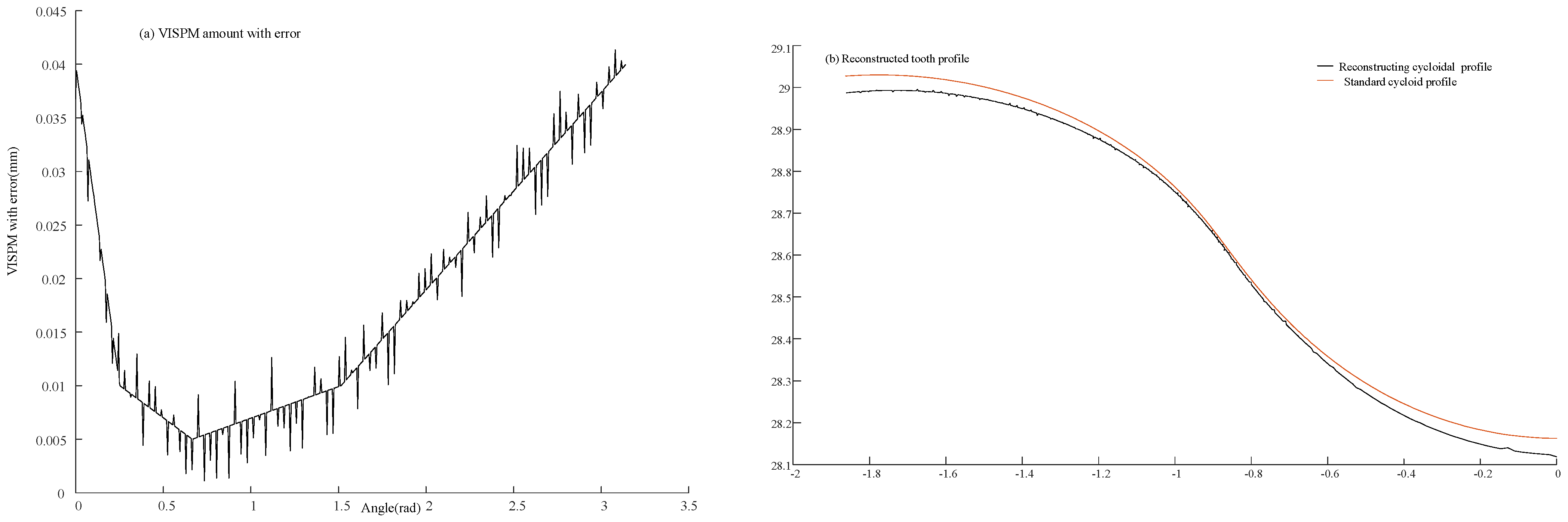
3.2. Reconstructing Cycloid Tooth Profile with Tooth Profile Error

Ken Shin Lin [12] added a micro value δa to the eccentricity a in the standard tooth profile equation of the cycloid gear to approximately simulate the tooth profile error. This method cannot accurately reflect the influence of the tooth profile error on TE and backlash in TCA. Here, the B-spline curve fitting method is used to reconstruct the cycloid tooth profile equation with tooth profile error. In addition, the machining error in the direction of tooth width is not considered.
(1)
Coordinate calculation of discrete points on cycloid gear profile with tooth profile error
The tooth profile error is defined as the deviation of the actual tooth profile from the designed tooth profile in a complete tooth profile on the end plane, which is along the normal direction of the designed tooth profile. According to the measurement principle of the tooth profile error, the measurement of the cycloid tooth profile error is to measure the deviation between the actual tooth profile and the designed tooth profile in a complete tooth profile along the normal direction of the designed tooth profile of the cycloid gear. Therefore, the actual tooth profile point can be obtained by adding the tooth profile error along the normal direction on the measured point of the designed tooth profile of the cycloid gear.
The modified tooth profile equation of the cycloid gear is Equation (3), and the homogeneous form is as follows
r c φ p = [ x c , y c , 0 , 1 ]
where x c and y c are the horizontal and vertical coordinates of the modified cycloid gear.
The derivation of parameter φ p in Equation (4) and unitization can obtain a unit normal vector of the tooth profile.
n c ( φ ) = d r c ( φ ) d φ × k d r c ( φ ) d φ × k
where vector k is the unit vector in the positive direction of the z-axis. That is, k = 0 , 0 , 1 . The direction of the unit normal vector is from the inside to the outside of the cycloid gear tooth.
Suppose the cycloid gear tooth profile deviation at each measuring point is δ φ i (i = 1, 2, 3…), the coordinates of measuring points on the actual tooth profile of the cycloid gear can be expressed as
X c = x c + n x c φ i δ φ i Y c = y c + n y c φ i δ φ i
where x c and y c are the horizontal and vertical coordinates of the designed tooth profile, and φ i is the meshing phase angle at measuring point.
(2)
Reconstruction of the cycloid gear profile with tooth profile error
The non-uniform B-spline meets the characteristics of high-precision fitting of the actual tooth profile curve of the cycloid gear [28]. Therefore, the cubic B-spline curve is selected to reconstruct the discrete measurement points of the cycloid gear. It can be expressed as follows
p u = i = 0 n d i N i , 3 u
Whose node vector U is
U = [ 0 , 0 , 0 , u 4 , , u n , 1 , 1 , 1 ]
where p u is the B-spline curve function. d i represents the control points and N i , 3 u represents the basis functions. u is the parameter of the node vector U . In this article, p u represents the cycloid gear profile with tooth profile error. u and d i are calculated according to the measured points. N i , 3 u can be calculated by u and basis functions.
The basis function adopts the de Boor–Cox recursive formula, and can be defined as
N i , 0 u = 1       u i u < u i + 1 0         o t h e r w i s e N i , 3 ( u ) = u u i u i + 3 u i N i , 2 ( u ) + u i + 4 u u i + 4 u i + 1 N i + 1,2 ( u )
where 0/0 is defined as 0.
When the control point di and node vector U are known, the corresponding points on the curve can be calculated through Equations (17)–(19). The measured tooth points are not the control points of the fitting curve; they can be used to obtain the node vector U and control points by inverse solution. Then, the B-spline curves can be obtained using Equations (17)–(19).
Step 1: Solving the node vector. Two methods are usually used to inversely calculate the node vector: even-chord-length parameterization and accumulated-chord-length parameterization. Here, the accumulated-chord-length parameterization is used to parameterize the measured tooth points q i (i = 0, 1, …, n − 2) according to the measured method. As the cubic B-spline curve passes through the endpoint of the fitting curve, the nodes at both ends are quadruple nodes [29], so the node vector can be calculated by the following formula
u 0 = u 1 = u 2 = u 3 = 0 u i + 3 = j = 0 i 1   q j + 1 q j j = 0 n 3   q j + 1 q j ,   i = 1 ,   2 , ,   n 3 u n + 1 = u n + 2 = u n + 3 = u n + 4 = 1
Step 2: Calculating the control vertices inversely. Substituting the measured points q i into Equation (17), the cubic B-spline curve equations can be obtained
q k = p u k = i = 0 n d i N i , 3 u k   i = 3 ,   4 , ,   n + 1
Substitute the node vector obtained from Equation (20) into Equation (21) to obtain
N 0,3 u 3 N 1,3 u 3 N 1,3 u 4 N n 3,3 u n N 2,3 u 3 N 2,3 u 4 N n 2,3 u n N n 2,3 u n + 2 N 3,3 u 4 N n 1,3 u n N n 1,3 u n + 2 N n , 3 u n + 2 n 1 × n + 1 d 0 d 2 d n 1 d n = q 0 q 1 q n 3 q n 2
where the empty entries are all zero.
Equation (22) has n + 1 unknown control points and n 1 equations. Since the first and last nodes of the node vector take four multiple nodes, the first and last control points coincide with the first and last measurement points. That is, d 0 = q 0 , d n 2 = q n 2 , the number of equations becomes n + 1 , so the control vertexes can be obtained.
Step 3: Reconstructing the mathematical model of cycloid tooth profile. By substituting the obtained control vertexes d i ( i = 1 ,   2 , ,   n ) and node vector U into Equation (17), the mathematical model of the cycloid tooth profile equation including tooth profile error can be obtained
R c = R ( u )   ( 0 u 1 )

3.3. Solving the TCA with Tooth Profile Error (ETCA)

The B-spline curve fitting method can establish the cycloid gear tooth profile equation containing the tooth profile error. In this section, the fitting tooth profile equation is used to carry out the TCA. Compared with the standard TCA, the ETCA has different tooth profile equations and different solving methods. When there is no manufacturing error, the tooth profile equation of the cycloid gear is the theoretical tooth profile equation or the designed tooth profile equation, which is derived from the modification method. When considering the tooth profile error, the actual tooth profile points are calculated according to the designed tooth profile and the tooth profile error of the cycloid gear, and then the actual tooth profile equation of the cycloid gear is derived by using the cubic B-spline curve fitting. The final tooth profile equation is not a fixed equation, but an accumulation form of the cubic spline curve equation, which is not easy to calculate by using the “fsolve” function in MATLAB [30]. Therefore, it is necessary to find a simpler and easier calculation method. Considering that the calculation principle of the Newton–Raphson algorithm is the first-order linear approximate calculation of Taylor expansion of the equations, the Taylor expansion form of the TCA equations can be easily obtained by the first derivation.
The flow chart of ETCA is shown in Figure 5.

Newton–Raphson Algorithm for Solving TCA Equations with Tooth Profile Error

The tooth profile equation of the actual tooth profile is shown in Equation (23). The TCA equations of the actual tooth profile can be obtained by substituting the tooth profile equation of the actual tooth profile into the original TCA Equation (9). So, the ETCA equation can be expressed as
R f c , i ( u , φ i n , φ c , i ) = r f p , i θ p , i n f c , i ( u , φ i n , φ c , i ) = n f p , i θ p , i
where R f c , i ( u , φ i n , φ c , i ) is the tooth profile expression of the actual tooth profile in S f , u is the curve fitting parameter, φ c , i is the cycloid gear rotation angle. r f p , i θ p , i is the position vector of the pin tooth profile in the S f . n f c , i and n f p , i are the unit normal vectors of cycloid gear and pin gear at meshing points in S f , respectively.
The scalar form of TCA equation can be obtained by projecting the vector equation onto each coordinate axis, which can be expressed as follows
X f c , i u , φ i n , φ c , i = X f p , i θ p , i Y f c , i u , φ i n , φ c , i = Y f p , i θ p , i n f x c , i ( u , φ i n , φ c , i ) = n f y p , i θ p , i
Deforming Equation (25) to obtain
f 1 = X f c , i u , φ i n , φ c , i X f p , i θ p , i = 0 f 2 = Y f c , i u , φ i n , φ c , i Y f p , i θ p , i = 0 f 3 = n f x c , i u , φ i n , φ c , i n f y p , i θ p , i = 0
They are uniformly expressed as
F ( φ c , i , u , θ p , i ) = F ( f 1 ( φ c , i , u , θ p , i ) , f 2 ( φ c , i , u , θ p , i ) , f 3 ( φ c , i , u , θ p , i ) ) = 0
The solving principle of the Newton–Raphson algorithm is as follows: Suppose x * is the solution of the equations, and its k-th approximate solution is x ( k ) , then the Taylor expansion of the multivariate function can be obtained:
F ( x * ) = F ( x ( k ) ) + F ( x ( k ) ) ( x * x ( k ) ) + R ( x * x ( k ) ) = 0
where
l i m Δ x 0 R ( Δ x ) Δ x = 0
Therefore, when x ( k ) is very close to x * , the terms R ( x * x ( k ) ) can be omitted, so the equations can be linearly expressed as
F ( x ( k ) ) = F ( x ( k ) ) Δ x
where Δ x = ( x * x ( k ) ) , let Δ x = ( x ( k + 1 ) x ( k ) ) , then
x ( k + 1 ) = x ( k ) + Δ x = x ( k ) [ F ( x ( k ) ) ] 1 F ( x ( k ) ) ,     k = 0 ,   1 ,   2 ,   n
Therefore, the key to solving Equation (26) is to obtain the first-order partial derivative of all variables in F ( φ c , i , u , θ p , i ) , namely the Jacobi matrix F ( x ( k ) ) . X f c , i u , φ i n , φ c , i , Y f c , i u , φ i n , φ c , i , and n f x c , i u , φ i n , φ c , i are piecewise functions, which cannot be directly derived from the partial derivative formula for each variable in Equation (31). Here, the definition of derivative is used to approximate the Jacobi matrix. The partial derivative f 1 / u of parameter u is taken as an example to illustrate the solution method. Assuming a small amount Δ u , then f 1 / u can be approximately expressed as
f 1 u = l i m Δ u 0 f 1 ( u + Δ u , ϕ 2 , β ) Δ u f 1 ( u + Δ u , ϕ 2 , β ) Δ u
So, the Jacobi matrix F ( x ( k ) ) can be obtained
F ( x ( k ) ) = f 1 u       f 1 φ c , i       f 1 θ p , i f 2 u     f 2 φ c , i       f 2 θ p , i   f 3 u     f 3 φ c , i     f 3 θ p , i
The solution of Equation (33) can be expressed as
u ( k + 1 ) φ c , i ( k + 1 ) θ p , i ( k + 1 ) = u ( k ) φ c , i ( k ) θ p , i ( k ) [ F ( x ( k ) ) ] 1 f 1 ( u ( k ) , φ c , i ( k ) , θ p , i ( k ) ) f 2 ( u ( k ) , φ c , i ( k ) , θ p , i ( k ) ) f 3 ( u ( k ) , φ c , i ( k ) , θ p , i ( k ) )
where x ( k ) = [ u ( k ) , φ c , i ( k ) , θ p , i ( k ) ] T . After iterative calculation, when x ( k + 1 ) x ( k ) < σ , σ is the accuracy error, then x ( k + 1 ) is the solution of the equations. This algorithm can be used to solve the TCA Equation (24) of a cycloid gear containing tooth profile error, and the TE can be obtained by calculating the TE Equation (13). The flow chart of the Newton–Raphson algorithm for solving ETCA equations is shown in Figure 6.

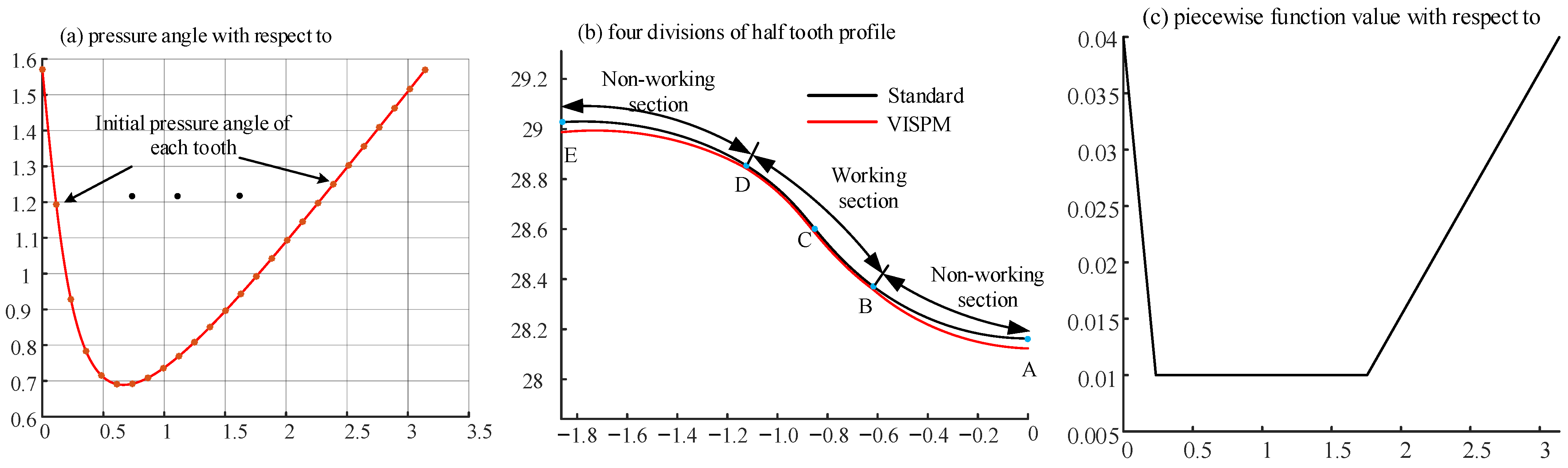
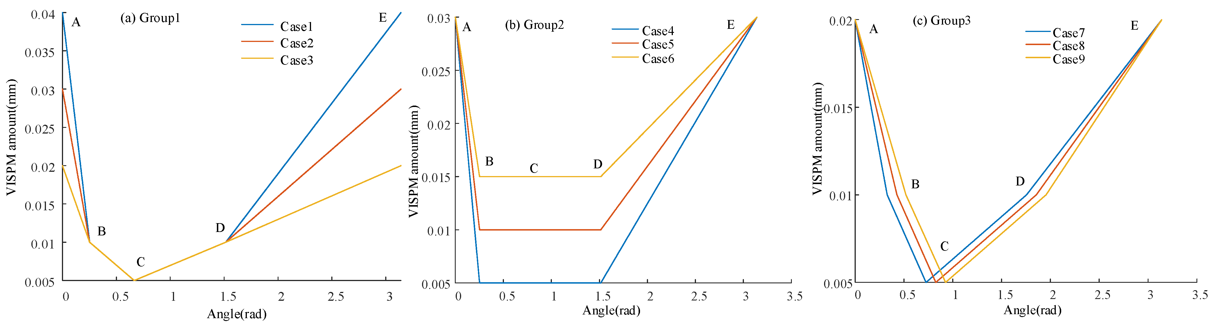
3.4. Meshing Characteristic of VISPM

In order to explore the influence of the VISPM modification method on the meshing characteristics of a CBR, the LTCA of CBR25 whose parameters are shown in Table 1 was carried out with different VISPM parameters, and the contact force, stress, deformation, and TE were analyzed.
The CBR25 is composed of bearing steel (GB/T18254-2016, GCr15) [31]. Its density, Poisson ratio, and elastic modulus are shown in Table 3. LTCA was carried out with three groups, and the load torque is Tout = 100 Nm. Each group has three cases, as shown in Table 4. The first group has different clearances of the non-working segment, and the same clearance of the working segment, as shown in Figure 7a. The second group has the same clearance of V R r p | A | E , and the working segment clearance has different numerical constants, as shown in Figure 7b. The third group has the same parameters of both the working segment and non-working segment, and φ p | B , φ p | C , and φ p | D have different phase angles of the working segment, as shown in Figure 7c. The tooth profile error data were simulated by the random number generated by the normal distribution function (mean value is 0 μm, standard deviation is 5 μm, and half-tooth has 158 error points). The VISPM amount with error of Case 1 is shown in Figure 8a, whose reconstructed half-tooth profile is shown in Figure 8b. As a comparison, all three groups used the same error data.
By LTCA, the contact force, stress, deformation and TE of the three groups can be obtained. Here, the meshing characteristics are given when the input angle is 72°, and are shown in Figure 9, Figure 10 and Figure 11. From Figure 9a–c, it can be seen that the maximum contact force, contact stress, and contact deformation of Case1 were the largest among the three, which were 816.5 N, 1757.9 MPa, and 1.92 μm, respectively, and occurred in pin No. 7. Those of Case 2 were the second largest, with values of 661.4 N, 1552.5 MPa, and 1.61 μm, and occurred in pin No. 7. Those of Case 3 were the smallest, with values of 427.2 N, 1278.2 MPa and 1.09 μm, and occurred in pin No. 10. The numbers of teeth in simultaneous contact were 11, 13, and 14, respectively. It can be seen from Figure 9d that their TE amplitudes were basically the same, which were 0.986′, 0.952′, and 0.916′, respectively. Due to the tooth profile error, their TE curves had high-frequency components. From Figure 10a–c, it can be seen that the maximum contact force, contact stress, and contact deformation of Case 4 were the smallest among the three, which were 591.4 N, 1450.1 MPa, and 1.44 μm, respectively, and occurred in pin No. 13. Those of Case 5 were the second smallest, which were 622.1 N, 1487.3 MPa, and 1.50 μm, respectively, and occurred in pin No. 13. Those of Case 6 were the largest, which were 929.6 N, 1818.1 MPa, and 2.1 μm, respectively, and occurred in pin No. 13. The numbers of teeth in simultaneous contact were 15, 15 and 12, respectively. From Figure 10d, it can be seen that their TE amplitudes were basically the same, which were 0.932′, 0.927′, and 0.964′, respectively. However, Case 4 had the smallest backlash, and Case 6 had the largest backlash. Also, their TE had high-frequency components due to tooth profile error. From Figure 11a–c, it can be seen that the maximum contact force, contact stress, and contact deformation of Case 8 were the largest among the three, which were 871.2 N, 1825.2 MPa, and 2.04 μm, respectively, occurring in pin No. 10. Those of Case 9 were the second largest, with values of 729.5 N, 1670.3 MPa, and 1.74 μm, respectively, occurring in pin No. 10. Those of Case 7 were the smallest, with values of 393.0 N, 1236.4 MPa, and 1.01 μm, respectively, occurring in pin No. 9. The numbers of teeth in simultaneous contact were 9, 10, and 12, respectively. From Figure 11d, it can be seen that their TE amplitudes were basically the same, which were 0.952′, 0.933′, and 0.924′, respectively. However, Case 9 had the smallest backlash, and Case 8 had the largest backlash. Also, their TE had high-frequency components due to tooth profile error.
From the above analysis, it can be concluded that the gap of the non-working section, that is, the gap between the tooth top and the tooth root, had little effect on the backlash and TE. When the gap of the non-working section was large, it had the maximum contact force, contact stress, and contact deformation. The working section clearance, that is, the amount of the BD section clearance, had a significant effect on the backlash. The larger the clearance, the larger the backlash. But it had little effect on the TE. When the working section clearance was large, it had the maximum contact force, contact stress, and contact deformation. When the phase angle of the working section was different, it had little influence on the backlash and TE. When the pressure angle corresponding to the phase angle of the working section was small, it had the minimum contact force, contact stress, and contact deformation. The tooth profile error affected the contact force, and the force distribution no longer conformed to the parabolic curve [7]. At the same time, it caused the TE curve to produce high-frequency components, and was closer to the measured TE curve.

4. Optimization of VISPM Based on PSO

The process of the influence of manufacturing error on the motion accuracy was very complex. The existence of manufacturing error changed the tooth profile of the cycloid gear, and then affected the transmission accuracy. The VISPM could flexibly control the isometric modification amount of the tooth profile with different meshing phase angles by adjusting the type of piecewise function and the coefficient of piecewise function, and then changing the tooth profile curve of the cycloid gear. In this section, the modification design of the cycloid gear tooth profile is carried out using VISPM based on the measured manufacturing error. To reduce the computational complexity, the modification amount of the AB and DE sections was linear, and BC and CD sections were constant, φ p | C takes the theoretical meshing phase angle, that is, φ p | C = 0.666 rad. V R r p | A | E , V R r p | B | C | D , φ p | B , and φ p | D are the design variables. V R r p | A | E represents V R r p | A = V R r p | E , and V R r p | B | C | D represents V R r p | B = V R r p | C = V R r p | D . The minimization of TE was objective, the optimal modification amounts and tooth profile curve of the cycloid gear were determined by an optimistic algorithm.

4.1. Optimization Model

(1)
Objective Function
TE is a very important parameter reflecting the transmission performance of a CBR, which determines the TE during the operation of a CBR. The optimization of TE can effectively improve the dynamic performance and reduce the vibration and noise of CBRs.
The TE can be calculated by ETCA in Section 3.3. The TE is affected by the coefficient of piecewise function, and can be expressed as
m i n f = m i n T E x 1 , x 2 , x 3 , x 4
where x 1 = V R r p | A | E , x 2 = V R r p | B | C | D , x 3 = φ p | B , and x 4 = φ p | D .
(2)
Design variables
In the optimization model, there are four design variables and the search space has four dimensions; the design variable X can be written as
X = [ x 1 , x 2 , x 3 , x 4 ] T
(3)
Constraint conditions
A. Lubrication and assembly constraints
0.015 x 1 0.1 ,   0.005 x 2 0.015 ,
B. Pressure angle constraints
0 < x 3 < 0.666 ,   0.666 < x 4 < π 2
(4)
Mathematical model
m i n f = m i n T E x 1 , x 2 , x 3 , x 4 s u b j e c t   t o 0.015 x 1 0.1 0.005 x 2 0.015 0 < x 3 < 0.666 0.666 < x 4 < π 2

4.2. Solving the Optimization Model

The optimization objective functions in this paper is the TE of the cycloid–pin gear pair, which is not directly related to the optimization variables, and cannot establish an accurate analytical expression from the optimization variables to the objective function. It cannot be solved by the traditional gradient-based optimization method, and the swarm intelligence optimization algorithm does not need the specific analytical expression of the objective function. Here, the PSO algorithm is used to solve the VISPM optimization model. The constraint condition of V R r p | A | E , V R r p | B | C | D , φ p | B , and φ p | D can determine the search space of PSO, and the objective function is used as the fitness function of PSO.

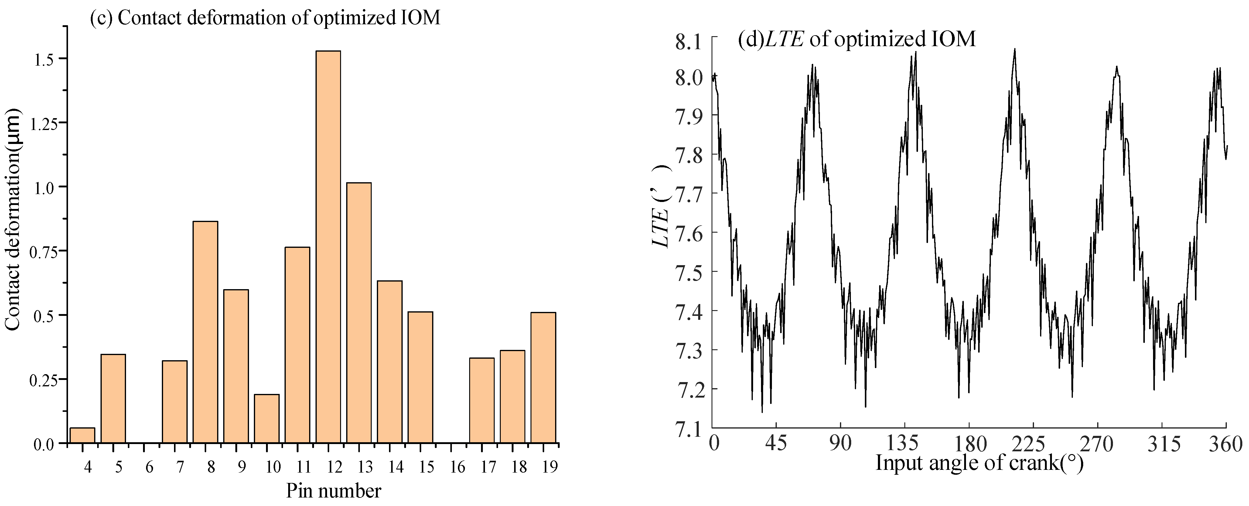
4.3. Example Analysis

Taking a CBR25 as an example, its parameters are shown in Table 1. In order to comprehensively consider the influence of error and modification on the CBR, the cycloid gear of the CBR25 was modified by VISPM. The cycloidal profile was measured using the three-coordinate measuring machine (CWT-544 AV-CNC, manufactured by Chien Wei Precise Technology Co., Ltd., Kaohsiung City, Taiwan) shown in Figure 12. The touch–touch trigger probe used in the measuring machine is the PH10 probe head and SP25 M probe produced by Renishaw Company (Gloucestershire, UK). The diameter of the ruby ball is 0.5 mm. The accuracy of the CMM is ±0.5 μm, and the resolution is 0.1 μm. The tooth profile error of each measured point could be directly obtained by using the cycloid gear error software module, where the equal meshing phase angle measurement method is selected, and the measured points distribution is shown in Figure 13. By measuring the completely cycloid profile, 37, 162 coordinate points are obtained. So half tooth contains 379 points, which are used to reconstruct the tooth. To reduce the computation, it is assumed that each cycloid tooth has the same tooth profile error. Finally, the ETCA model of cycloid-pin gear pair is established.
According to Section 3.2, the cycloid gear equation with tooth profile error of CBR25 can be calculated by Equation (23). Substituting it into the optimization model Equation (39), the VISPM optimization model with tooth profile error is obtained. There are four design variables in the optimization model, which are the variable isometric modification parameters x 1 = V R r p | A | E and x 2 = V R r p | B | C | D , and the sectional modification parameters x 3 = φ p | B and x 4 = φ p | D . The number of particle swarm individuals is SIZE = 100, and the maximum number of iterations is MAXGEN = 200. The fitness function is the ETCA program considering the tooth profile error with four design variables as parameters. The fitness function can be expressed as
F ( X ) = m i n   T E X X = [ x 1 , x 2 , x 3 , x 4 ] T = [ V R r p | A | E ,   V R r p | B | C | D ,   φ p | B ,   φ p | D ]
The position range of particle swarm can be expressed as
0.015 Δ V R r p | A | E 0.1 0.005       Δ V R r p | B | C | D 0.015   0 <     φ p | B       < 0.666 0   . 666 <     φ p | D < π / 2                
Figure 14 shows the iteration process. The optimal results are as follows: V R r p A E = 0.026 , V R r p | B | C | D = 0.005 , φ p | B = 0.265 , and φ p | D = 1.638 . And the maximum TE with T o u t = 100   Nm is 0.892 when the iteration is about 145 times.
Here, the contact force, contact stress, contact deformation, and TE of the optimized VISPM are shown in Figure 15 (also, the input angle is 72°). Figure 15a–c show the contact force, contact stress, and contact deformation by the optimal modification. The number of teeth in simultaneous contact was 15, and the maximum contact occurred in pin No. 13, whose contact force, contact stress, and contact deformation were 580.1 N, 1436.1 MPa, and 1.41 μm, respectively. Figure 15d shows the LTE curve, which also has high-frequency components affected by the tooth profile error.
Also, the cycloidal gear by IOM with the same profile error was modeled for optimization. It had two design variables, Δ R r p and Δ R p , and its constraints were Δ R p < 0 ,     Δ R r p < 0 ,     0.015 R r p R p 0.1 . The optimal results were Δ R r p = 0.026   m m and Δ R p = 0.058   m m . The contact force, contact stress, contact deformation, and TE of the optimized IOM are shown in Figure 16 (also, the input angle was 72°). The number of teeth in simultaneous contact was 14, and the maximum contact occurred in pin No. 12, whose contact force, contact stress, and contact deformation were 612.3 N, 1520.5 MPa, and 1.53 μm, respectively. Figure 16d shows the LTE curve, whose maximum TE is 0.942 .
By comparing Figure 15 with Figure 16, it can be concluded that the maximum contact force, maximum contact stress, and maximum TE of the VSIPM method were all less than those of the IOM method, with reductions of 5.26%, 5.55%, and 5.31% respectively. This indicates that the VSIPM method is superior to the IOM method in enhancing meshing characteristics.

5. Experimental Tests
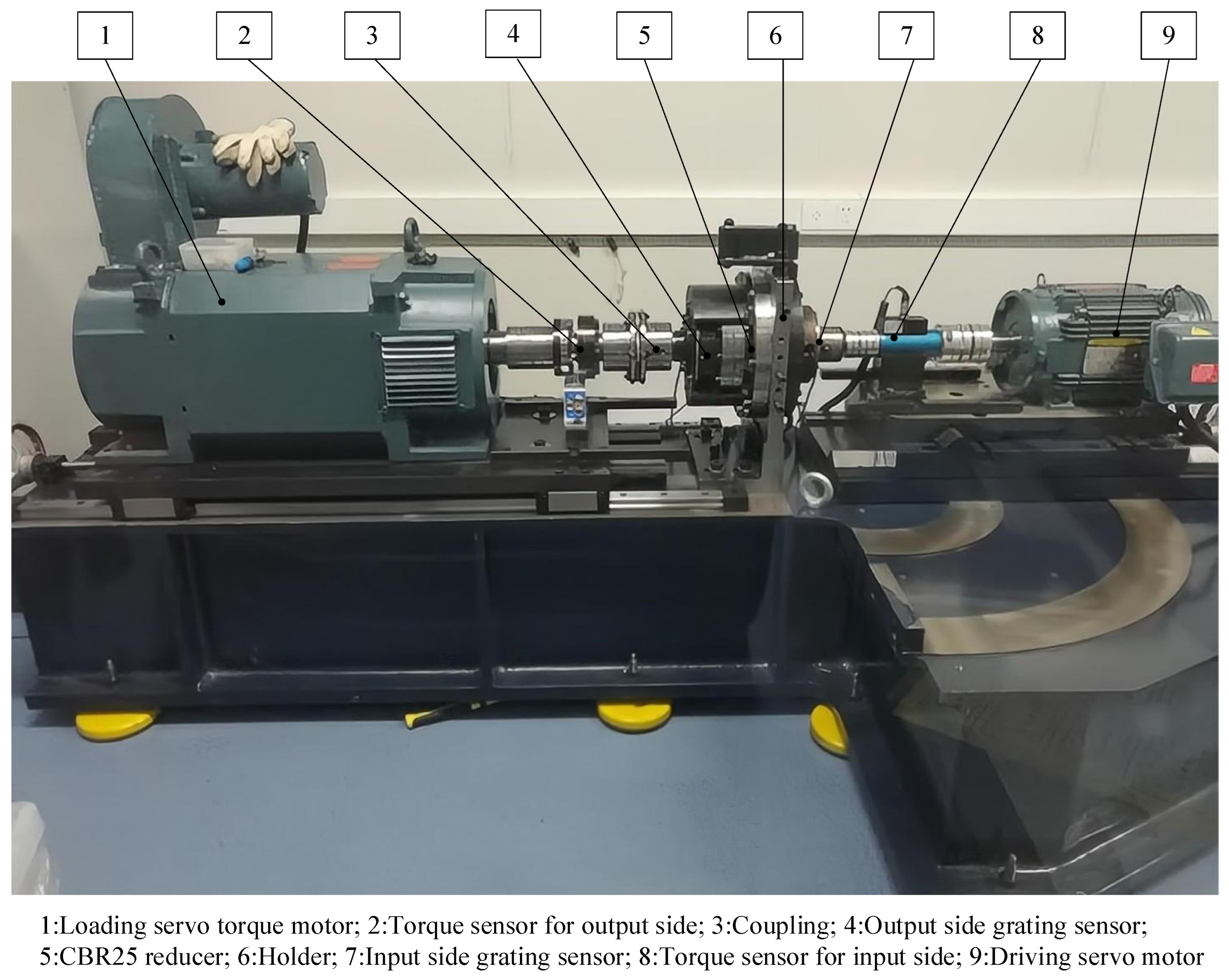
5.1. Test Platform

The prototype of the CBR25 (Jiangsu United Transmission Machinery Co., Ltd., Yangzhou, China) was manufactured with optimal VISPM and IOM. Figure 17a shows the assembly product, and Figure 17b shows the main parts. The comprehensive performance test bench is shown in Figure 18. It mainly consists of a driving servo motor, loading servo motor, two torque sensors, two grating sensors, couplings, and so on.

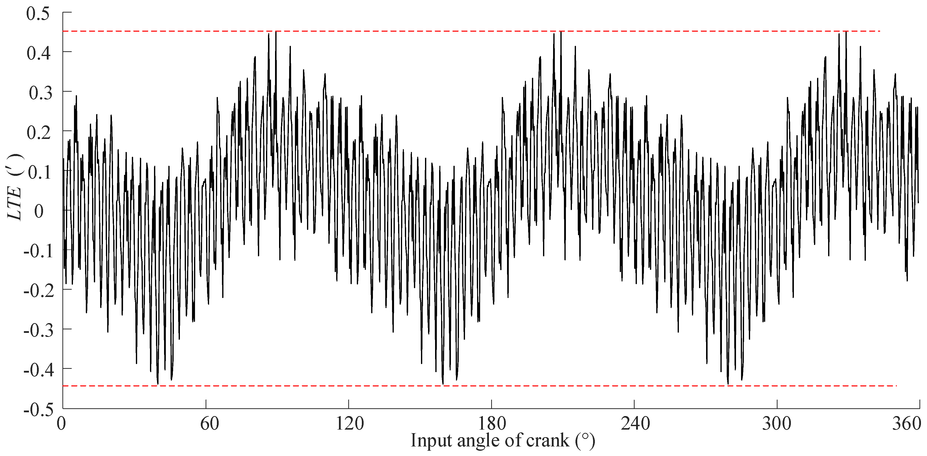
5.2. LTE Testing of CBR25 Prototype

The input and output ends of the CBR25 were connected to the driving and loading ends of the testing bench, respectively. The CBR25 was fixed in the flange of the holder. The driving servo motor rotated with a speed of 100 RPM, and the loading servo torque motor applied a 100 Nm load to the testing reducer. When the driving servo motor speed was stable (its fluctuation was less than 3 RPM), the input and output side grating sensor signals were synchronously collected by a digital card, and the sampling frequency was 200 Hz. Then, the LTE was calculated at every sampling time. The values of the output angle are the X-coordinate and the TEs are the Y-coordinate; the LTE curves with optimal VISPM and IOM were drawn as shown in Figure 19 and Figure 20, respectively. From Figure 19 and Figure 20, it can be seen that the testing LTE curve had no backlash because it was avoided when the driving servo motor speed was stable. The LTE values with optimal VISPM and IOM of CBR25 calculated by the LTE curve were 0.911′ and 0.958′. They were very close to the values of 0.892′ and 0.942′ calculated by LTCA. So, the simulation results were in good agreement with the results measured by the ETCA method.

6. Conclusions

In order to improve the transmission performance of CBRs, a VISPM method is proposed in this paper. A cubic B-spline fitting method was proposed to reconstruct the cycloidal tooth with tooth profile error, and the ETCA model was built. Taking the TE as the optimization objective, the optimization was carried out based on PSO, and the prototype was manufactured and experimental testing was carried out. The main conclusions are as follows:
(1)
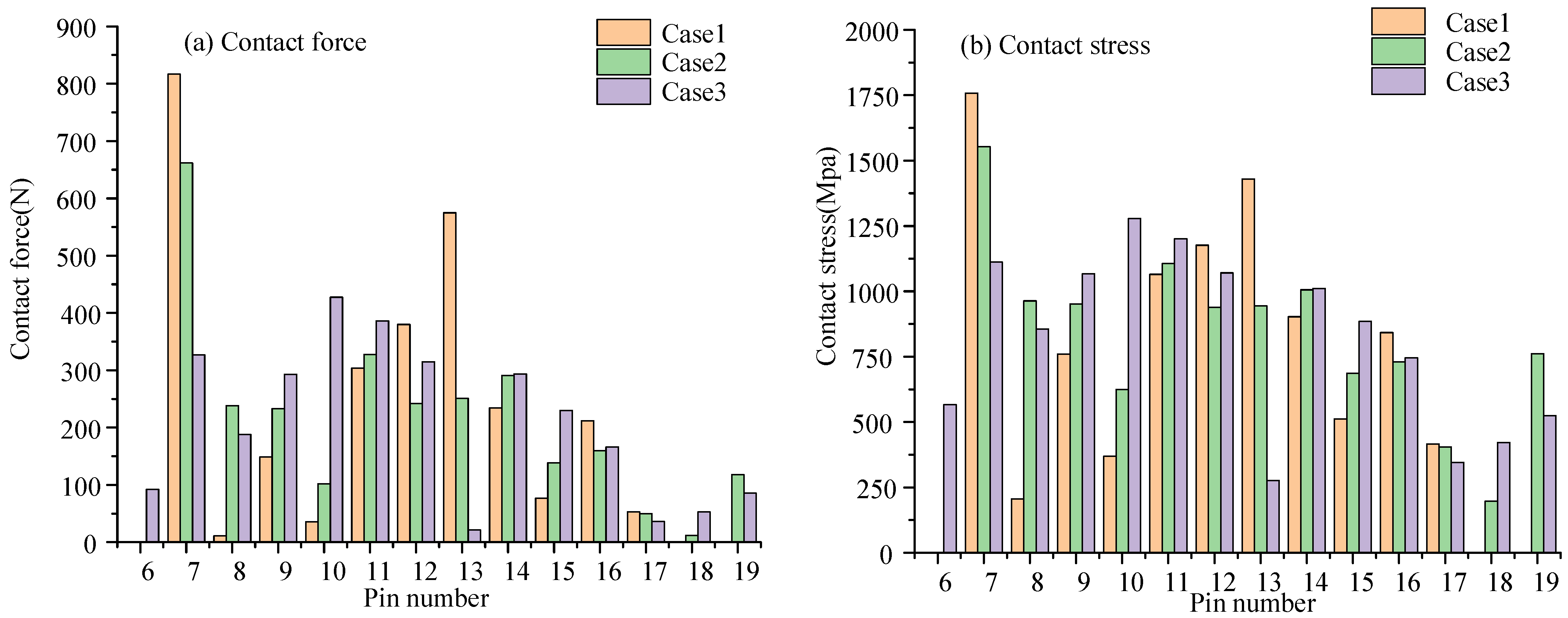
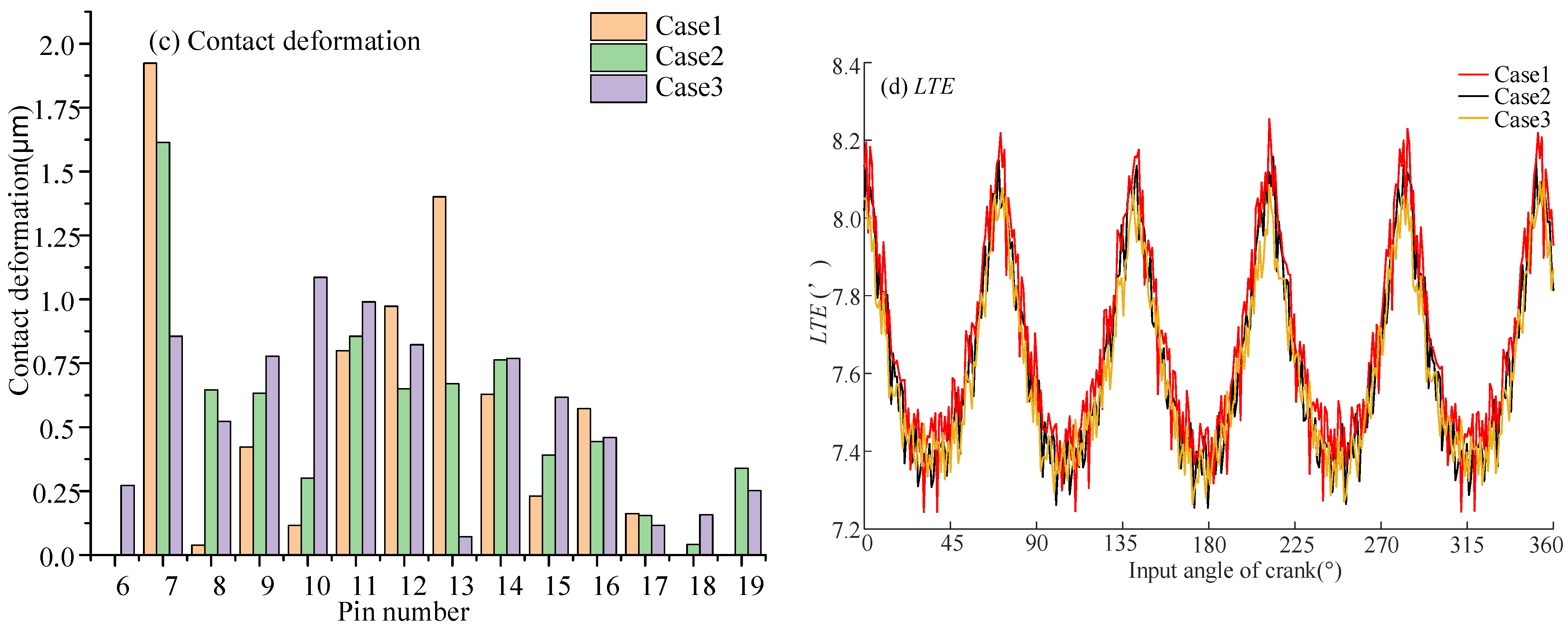
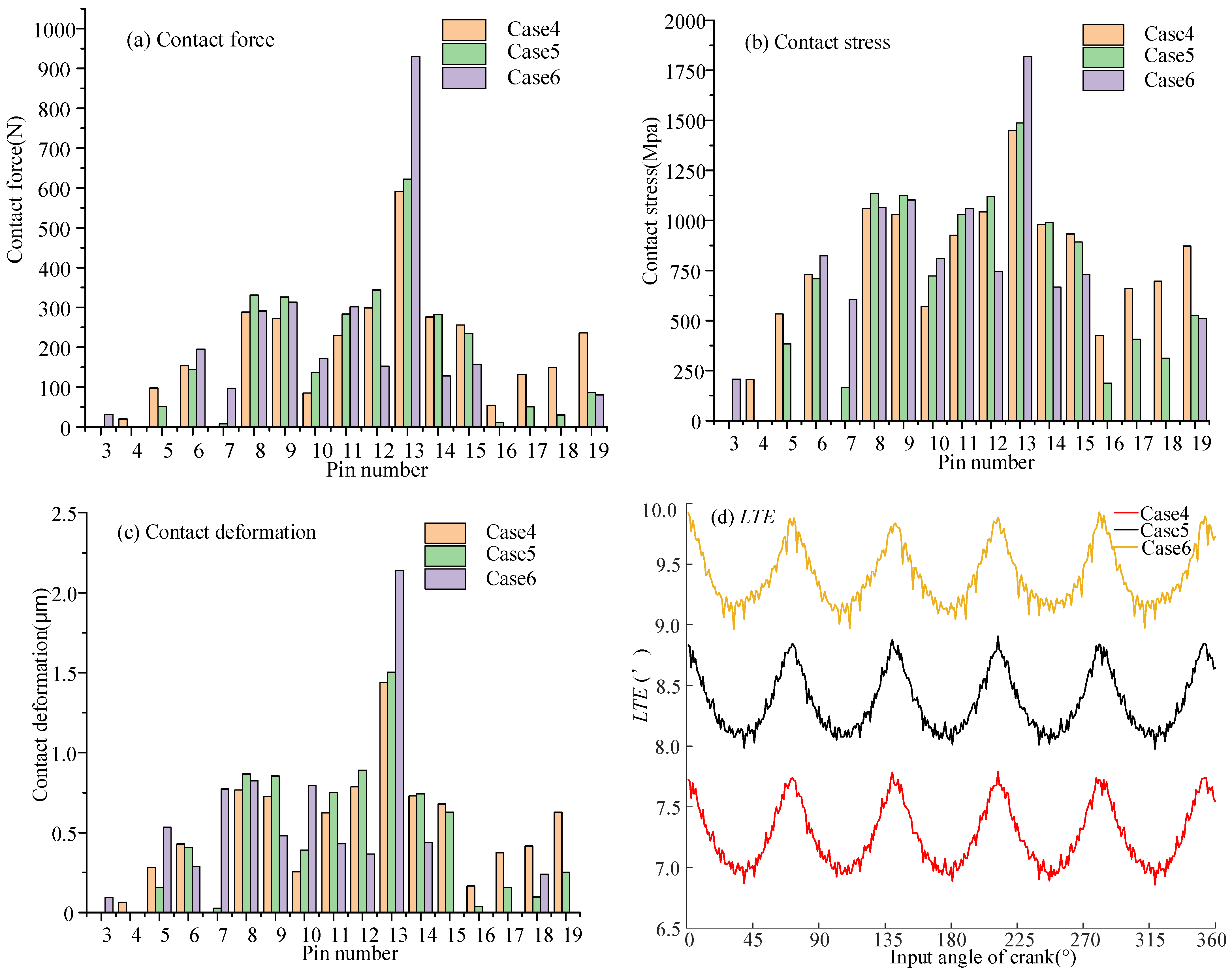
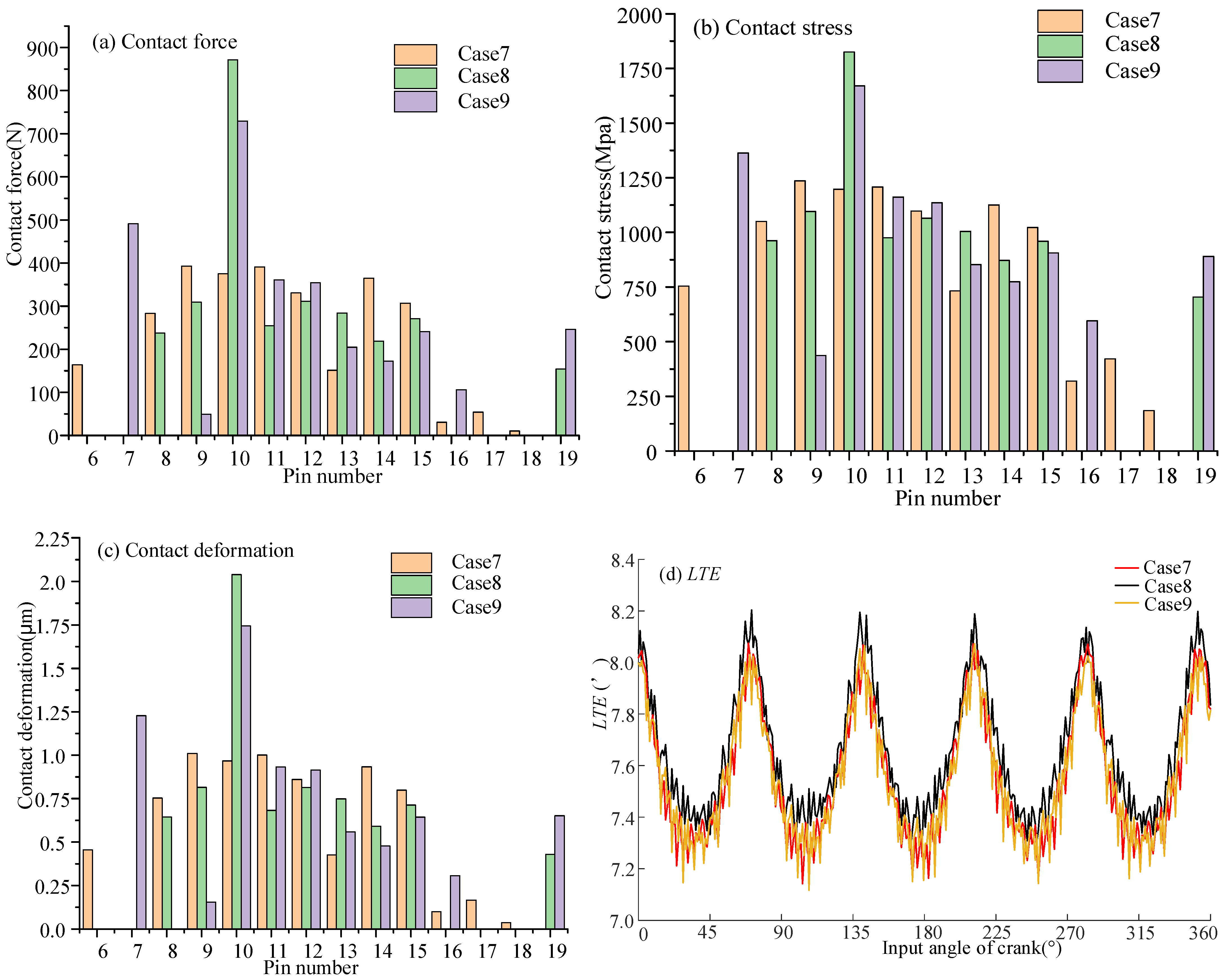
The VISPM can accurately control the modification amount of the working section and non-main working section of the tooth profile. The working section was selected according to the contact pressure angle to improve the loading capacity of the CBR reducer. The gap of the non-working section had little effect on the backlash and TE. The working section clearance had a significant effect on the backlash. But it had little effect on the TE. When the working section clearance was large, it had the maximum contact force, contact stress, and contact deformation. When the phase angle of the working section was different, it had little influence on the backlash and TE. When the pressure angle corresponding to the phase angle of the working section was small, it had the minimum contact force, contact stress, and contact deformation.
(2)
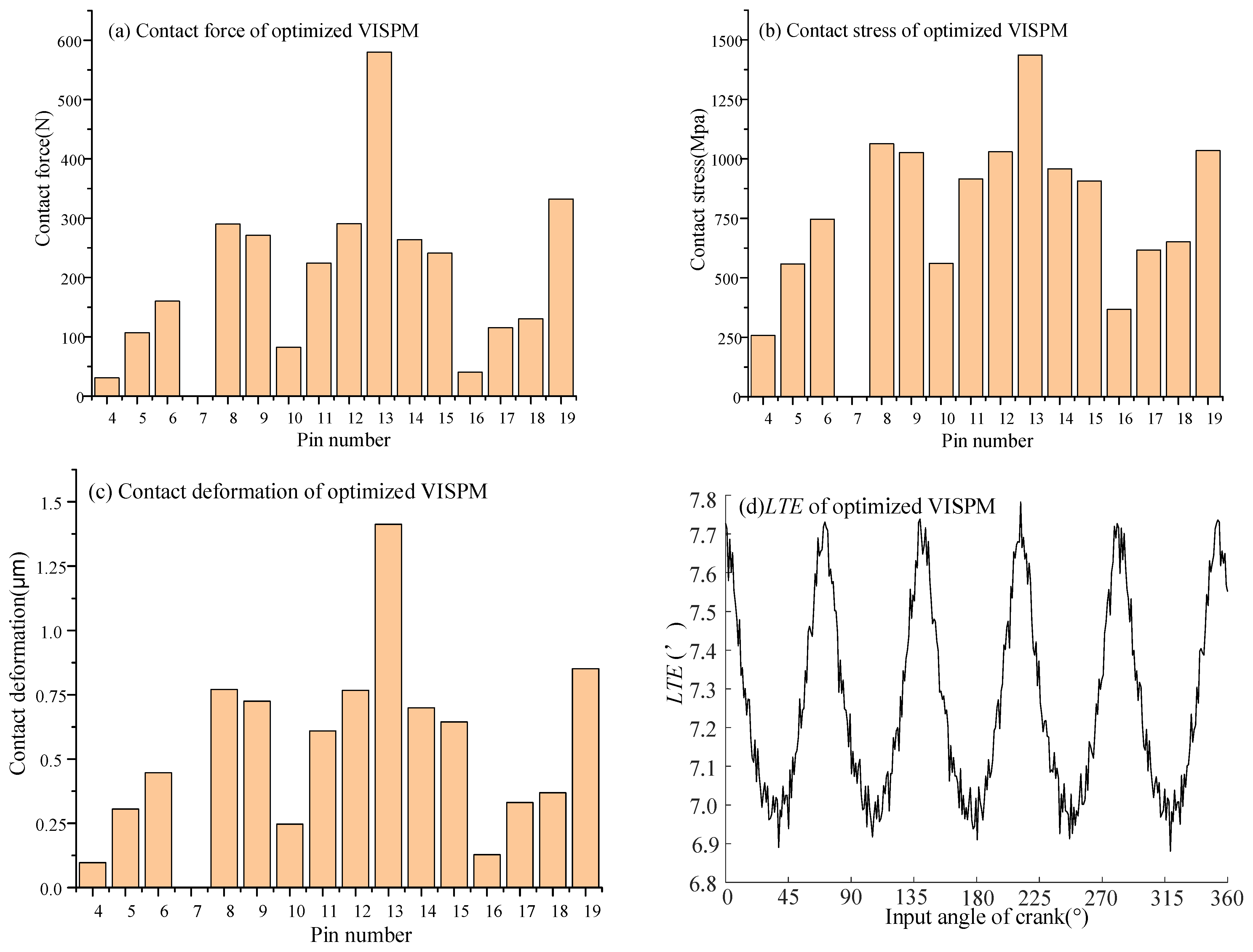
Taking the TE as the optimization objective, both the VISPM and IOM methods are optimized by the PSO algorithm for the CBR25. The maximum contact force, maximum contact stress, and maximum TE of the VSIPM method were all less than those of the IOM method, with reductions of 5.26%, 5.55%, and 5.31%, respectively. This indicates that the VSIPM method is superior to the IOM method in enhancing meshing characteristics.
(3)
The prototype of the CBR25 was manufactured with optimal VISPM and IOM, and the TE was tested on the testing bench. The test results demonstrate that the ETCA method was corrected for cycloid drive analysis, and the new VISPM method significantly enhanced the transmission performance of the CBR reducer.
The errors of the tooth width direction of cycloid gears were not considered, and will be addressed in future work. A three-dimensional tooth surface equation of cycloid gears with error will be constructed, and the relationship between topological modification and transmission performance will be studied.

Author Contributions

Conceptualization, X.S.; methodology, X.S.; software, X.S., Z.Q. and Y.X.; validation, X.S., Y.X. and J.H.; formal analysis, X.S.; investigation, X.S.; resources, X.S. and Z.Q.; data curation, X.S.; writing—original draft preparation, X.S.; writing—review and editing, X.S.; visualization, X.S.; supervision, X.S.; project administration, J.H.; funding acquisition, X.S. All authors have read and agreed to the published version of the manuscript.

Funding

This research was funded by the National Natural Science Foundation of China (Grant No. 52305062), Major Project of Philosophy and Social Science Research in Colleges and Universities of Jiangsu Province (Grant No. 2022SJYB0445).

Institutional Review Board Statement

Not applicable.

Informed Consent Statement

Not applicable.

Data Availability Statement

Data are contained within the article.

Acknowledgments

The authors express their gratitude for the funding support provided by the Nanjing Excellent Postdoctoral Research Project.

Conflicts of Interest

The authors declare no conflicts of interest.

Nomenclature

φ c Rotation angle of cycloid gear
φ p Rotation angle of roller gear
i H Transmission ratio of cycloid gear and roller gear
z c Teeth number of cycloid gear
z p Teeth number of roller gear
R p Radius of roller gear
R r p Radius of the roller
a Eccentricity of the input crank shaft
Δ R p Value of offset modification
Δ R r p Value of isometric modification
S f Fixed coordinate system in center of roller gear
S p Moving coordinate system in center of roller gear
S c Moving coordinate system in center of cycloid gear
O c Origin of S c
O p Origin of S p
V R r p Value of variable isometric modification
V R r p | A | E Modification amount of point A and E
V R r p | C Modification amount of point C
V R r p | B | D Modification amount of point B and D
φ p | B Position of points B
φ p | C Position of point C
φ p | D Position of point D
n f p , i Unit normal vector in S f for the contact point on the i-th point
n f c , i Unit normal vector of the i-th cycloid gear in S f
M f c Coordinate transformation matrix from S c to S f
r f c , i Contact point on the i-th cycloid gear in S f
r f p , i Contact point on the i-th pin in S f
θ c Angle parameter of cycloid gear
θ c , i 0 Meshing angle of cycloid gear at initial reference point
θ p , i 0 Meshing angle of pin gear at initial reference point
r g Pitch circle radius of the cycloid gear
r b Pitch circle radius of the roller gear
φ i n Input crank angle
φ c , i Output angle of cycloid gear corresponding to i-th roller
θ p , i Angle parameter of i-th roller
θ c , i Parametric angle of cycloid gear corresponding to i-th roller
φ o u t Output angle of cycloid gear
δ φ i Cycloidal gear tooth profile deviation at each measuring point
p u B-spline curve function
N i , 3 u Basis function
d i Control point
α K Pressure angle

References

  1. Blanche, J.G.; Yang, D.C.H. Cycloid drives with machining tolerances. J. Mech. Transm. Autom. Des. 1989, 111, 337–344. [Google Scholar] [CrossRef]
  2. Yang, D.C.H. Design and Application Guidelines for Cycloid. Mech. Mach. Theory 1990, 25, 487–501. [Google Scholar] [CrossRef]
  3. Zhang, L.; Xu, W.; Zhi, Y.; Hou, N.; Li, H.; Wang, C.; Li, T.; Zhang, Y.; Zhang, H.; Chen, J. Optimization of Tooth Profile Modification and Backlash Analysis of Multi-tooth Mesh Cycloid Transmission. Manuf. Technol. 2024, 24, 154–163. [Google Scholar] [CrossRef]
  4. Song, X.; Chen, Y.; Yang, J. Study of the Transmission Characteristics of the Cycloid Gear Based on a Multi-Objective Optimization Modification. Machines 2023, 11, 775. [Google Scholar] [CrossRef]
  5. Lin, W.S.; Shih, Y.P.; Lee, J.J. Design of a two-stage cycloidal gear reducer with tooth modifications. Mech. Mach. Theory 2014, 79, 184–197. [Google Scholar] [CrossRef]
  6. Hong-Liu, Y.; Jin-hua, Y.; Xin, H.; Ping, S. Study on teeth profile modification of cycloid reducer based on non-hertz elastic contact analysis. Mech. Res. Commun. 2013, 48, 87–92. [Google Scholar] [CrossRef]
  7. Sun, X.; Han, L.; Wang, J. Design and transmission error analysis of CBR reducer. J. Mech. Des. 2019, 141, 082301. [Google Scholar] [CrossRef]
  8. Li, X.; Li, C.; Wang, Y.; Chen, B.; Lim, T.C. Analysis of a cycloid speed reducer considering tooth profile modification and clearance-fit output mechanism. J. Mech. Des. 2017, 139, 033303. [Google Scholar] [CrossRef]
  9. Wu, S.; Guo, R.; Li, X. Quasi-Static Force Analysis and Tooth Profile Modification Optimization of the Cycloid Speed Reducer. Appl. Sci. 2024, 14, 845. [Google Scholar] [CrossRef]
  10. Sun, X.; Han, L.; Wang, J. Tooth modification and loaded tooth contact analysis of china bearing reducer. Proc. Inst. Mech. Eng. Part C J. Mech. Eng. Sci. 2019, 233, 6240–6261. [Google Scholar] [CrossRef]
  11. Ren, Z.-Y.; Mao, S.-M.; Guo, W.-C.; Guo, Z. Tooth modification and dynamic performance of the cycloidal drive. Mech. Syst. Signal Process. 2017, 85, 857–866. [Google Scholar] [CrossRef]
  12. Lin, K.-S.; Chan, K.-Y.; Lee, J.-J. Kinematic error analysis and tolerance allocation of cycloidal gear reducers. Mech. Mach. Theory 2018, 124, 73–91. [Google Scholar] [CrossRef]
  13. Sensinger, J.W. Unified Approach to Cycloid Drive Profile, Stress, and Efficiency Optimization. J. Mech. Des. 2010, 132, 024503. [Google Scholar] [CrossRef]
  14. Sensinger, J.W. Efficiency of High-Sensitivity Gear Trains, Such as Cycloid Drives. J. Mech. Des. 2013, 135, 71006. [Google Scholar] [CrossRef]
  15. Zhang, Y.; Huang, J.; He, W. Multi-objective optimization of cycloidal gear based on segmental modification of pressure angle. J. Mech. Sci. Technol. 2022, 36, 3535–3545. [Google Scholar] [CrossRef]
  16. Gao, S.; Zhang, Y.; Li, Y.; Ji, S.; Wei, T.; Wang, Z. Piecewise Modification of Cycloidal Gear in RV Reducer: Application of Spline Interpolation Theory and Comparison with a Combination Modification Optimization Method. Int. J. Precis. Eng. Manuf. 2024. [Google Scholar] [CrossRef]
  17. Tran, T.L.; Pham, A.D.; Ahn, H.-J. Lost motion analysis of one stage cycloid reducer considering tolerances. Int. J. Precis. Eng. Manuf. 2016, 17, 1009–1016. [Google Scholar] [CrossRef]
  18. Li, T.; Tian, M.; Xu, H.; Deng, X.; An, X.; Su, J. Meshing contact analysis of cycloidal-pin gear in rv reducer considering the influence of manufacturing error. J. Braz. Soc. Mech. Sci. 2020, 42, 133. [Google Scholar] [CrossRef]
  19. Wang, J.; Lv, H. Modification and Optimization of Cycloidal Gear Tooth Profile Based on Machining Error Compensation. Appl. Sci. 2023, 13, 2581. [Google Scholar] [CrossRef]
  20. Antoniak, P.; Bednarczyk, S. Determination of Mechanical Power Loss of the Output Mechanisms with Serially Arranged Rollers in Cycloidal Gears While Taking into Account Manufacturing Tolerances. Machines 2024, 12, 345. [Google Scholar] [CrossRef]
  21. Xu, L.X. A dynamic model to predict the number of pins to transmit load in a cycloidal reducer with assembling clearance. Proc. Inst. Mech. Eng. Part C J. Mech. Eng. Sci. 2019, 233, 4247–4269. [Google Scholar] [CrossRef]
  22. Sun, X. Design Theory and Experimental Research of CBR Reducer for Robot. Ph.D. Thesis, School of Mechanical Engineering, Southeast University, Nanjing, China, 2019. [Google Scholar]
  23. Qi, F.; Wilcox, L. New developments in tooth contact analysis (TCA) and loaded TCA for spiral bevel and hypoid gear drives. Gear Tech. 2007, 24, 26–35. [Google Scholar]
  24. Demenego, A.; Vecchiato, D.; Litvin, F.L.; Nervegna, N.; Manc, S. Design and simulation of meshing of a cycloidal pump. Mech. Mach. Theory 2002, 37, 311–332. [Google Scholar] [CrossRef]
  25. Shuaifeng, L.; Xiaozhong, D.; Tianxing, L.; Changlu, W.; Jingzhao, Y. Tooth contact analysis of cycloidal pinwheel drive in rv reducer of robot. J. Mech. Trans. 2017, 41, 17–22. [Google Scholar]
  26. Jingzhao, Y. Load Contact Analysis of Cycloidal-Pin Gear Drive of Robot RV Reducer. Master’s Thesis, Henan University of Science and Technology, Luoyang, China, 2018. [Google Scholar]
  27. Lixin, X.; Yuhu, Y. A general method for multi-tooth contact analysis of cycloid-pin gear transmission. China Mech. Eng. 2016, 27, 1382–1388. [Google Scholar]
  28. Piegl, L.; Tiller, W. The NURBS Book, 2nd ed.; Springer: Berlin, Germany, 1997. [Google Scholar]
  29. Ma, K.; Han, L.; Sun, X.; Liang, C.; Zhang, S.; Shi, Y.; Wang, X. A path planning method of robotic belt grinding for workpieces with complex surfaces. IEEE-ASME T. Mech. 2020, 25, 728–738. [Google Scholar] [CrossRef]
  30. Zhenglin, W.; Chun, G.; Qian, H. Proficient in MATLAB Scientific Computing; Publishing House of Electronics Industry: Beijing, China, 2009. [Google Scholar]
  31. GB/T18254; High-Carbon Chromium Bearing Steel. China Iron and Steel Association: Beijing, China, 2016.
Figure 1. Exploded structure of a CBR.
Machines 12 00915 g001
Figure 2. Schematic diagram of VISPM.
Machines 12 00915 g002
Figure 3. Shape of half-tooth profile with three different VISPM parameters.
Machines 12 00915 g003
Figure 4. Coordinate system of TCA.
Machines 12 00915 g004
Figure 5. ETCA flow chart.
Machines 12 00915 g005
Figure 6. Flow chart of Newton–Raphson algorithm to solve ETCA.
Machines 12 00915 g006
Figure 7. VISPM amount of three groups.
Machines 12 00915 g007
Figure 8. VISPM amount with error and reconstructed tooth profile of Case 1.
Machines 12 00915 g008
Figure 9. Meshing characteristics of group 1.
Machines 12 00915 g009aMachines 12 00915 g009b
Figure 10. Meshing characteristics of group 2.
Machines 12 00915 g010
Figure 11. Meshing characteristics of group 3.
Machines 12 00915 g011
Figure 12. The CWT-544AV-CNC CMM and its probe.
Machines 12 00915 g012
Figure 13. Sampling points of equal meshing phase angle measurement.
Machines 12 00915 g013
Figure 14. Fitness function curve.
Machines 12 00915 g014
Figure 15. Meshing characteristics of optimized VISPM.
Machines 12 00915 g015
Figure 16. Meshing characteristics of optimized IOM.
Machines 12 00915 g016aMachines 12 00915 g016b
Figure 17. Prototype of CBR25.
Machines 12 00915 g017
Figure 18. Comprehensive performance test bench.
Machines 12 00915 g018
Figure 19. LTE curve of CBR25 with VISPM.
Machines 12 00915 g019
Figure 20. LTE curve of CBR25 with IOM.
Machines 12 00915 g020
Table 1. Basic parameters of cycloid gear.
NameParameter Value
Number of cycloid teeth z c 49
Number of pin teeth z p 50
Radius of pin R r p /mm0.975
Eccentricity a /mm0.462
Radius of pin position circle R p /mm29.6
Table 2. Parameters of VISPM.
NameCase1Case2Case3
V R r p | A | E /mm0.050.030.02
V R r p | C /mm0.0050.0050.005
V R r p | B | D /mm0.020.0150.01
φ p | B 0.2520.30.2
φ p | C 0.6660.6660.666
φ p | D 1.5151.7561.245
Table 3. Material properties of CBR 25.
DensityPoisson RatioElastic Modulus
7800 kg/m30.32.1 × 1011 N/m2
Table 4. Groups of VISPM.
VISPM GroupsGroup 1Group 2Group 3
CasesCase 1Case 2Case 3Case 4Case 5Case 6Case 7Case 8Case 9
V R r p | A | E /mm0.040.030.020.030.030.030.020.020.02
V R r p | C /mm0.0050.0050.0050.0050.010.0150.0050.0050.005
V R r p | B | D /mm0.010.010.010.0050.010.0150.010.010.01
φ p | B 0.2520.2520.2520.2520.2520.2520.3280.4280.528
φ p | C 0.6660.6660.6660.6660.6660.6660.7260.8260.926
φ p | D 1.5151.5151.5151.5151.5151.5151.7561.8561.956
Disclaimer/Publisher’s Note: The statements, opinions and data contained in all publications are solely those of the individual author(s) and contributor(s) and not of MDPI and/or the editor(s). MDPI and/or the editor(s) disclaim responsibility for any injury to people or property resulting from any ideas, methods, instructions or products referred to in the content.

