
Optimization Design of Novel Consequent Pole Motor for Electric Power Steering System


Abstract
1. Introduction
- (1)
- Introduction of a novel CPM design with an additional iron pole (AIP) extension that optimizes the magnetic flux path and enhances torque performance while maintaining the same magnet volume.
- (2)
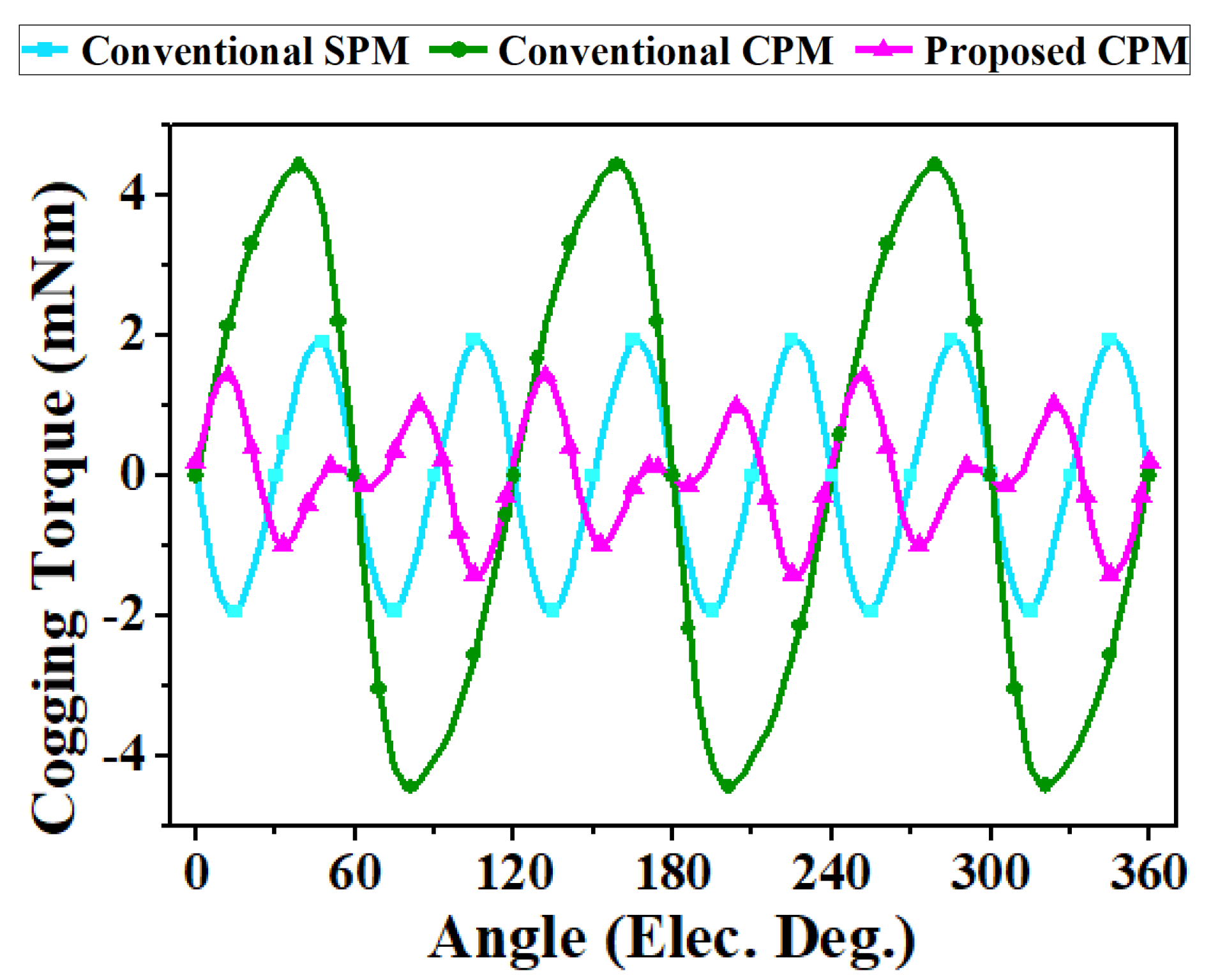
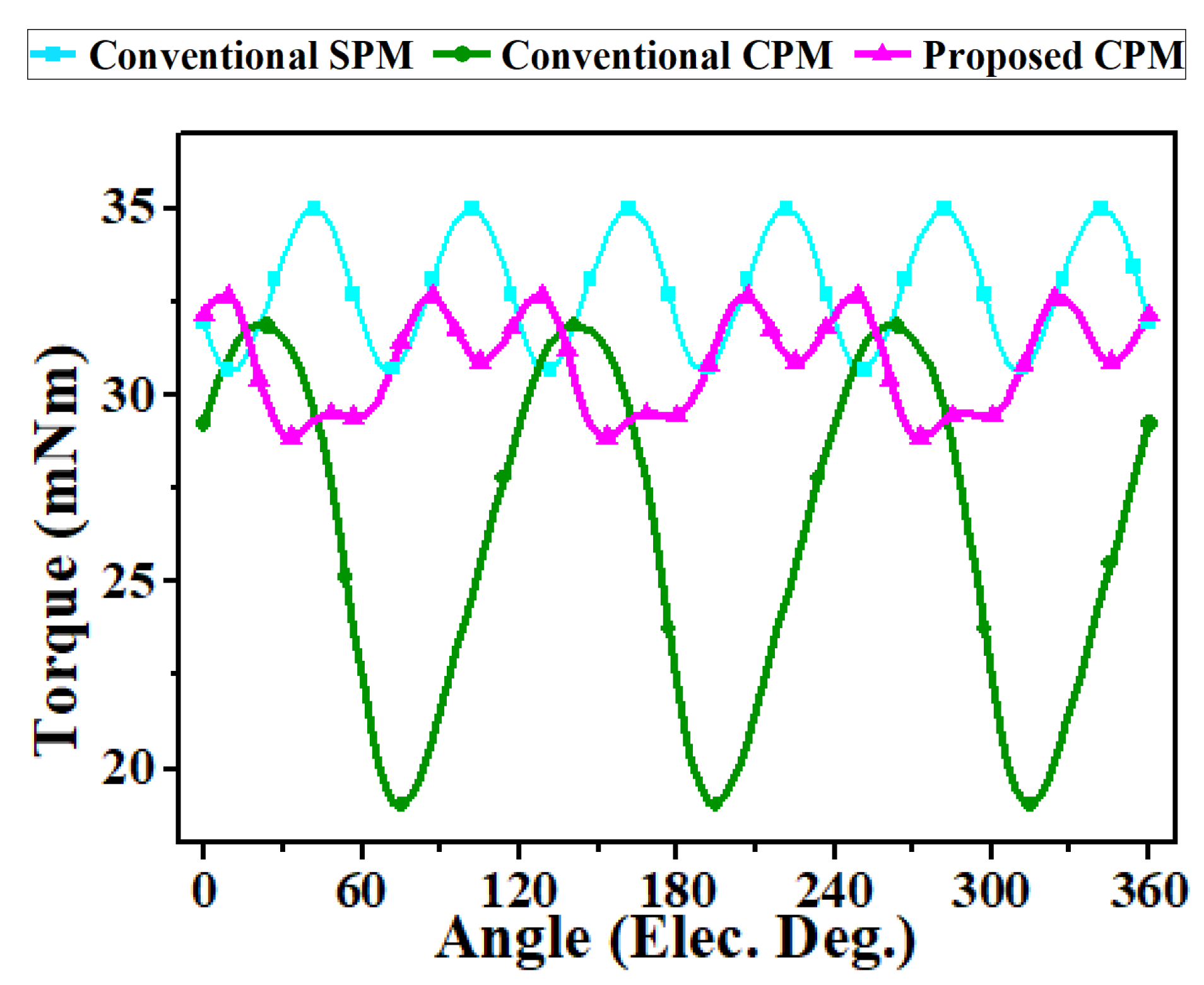
- Significant reduction in cogging torque (68%) and torque ripple (75%) compared to conventional CPMs, achieving improved torque stability and smooth motor operation.
- (3)
- Increased torque per magnet volume by 16% compared to conventional CPMs, highlighting more efficient use of magnetic material.
- (4)
- Presentation of a design approach that reduces reliance on rare-earth permanent magnets, contributing to cost-effective and sustainable motor development for industrial and automotive applications.
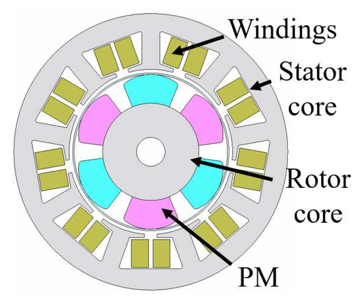
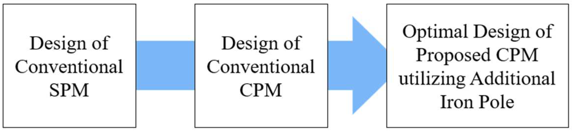
2. SPM Design for Electric Power Steering Motor in Tilt and Telescopic Steering Columns
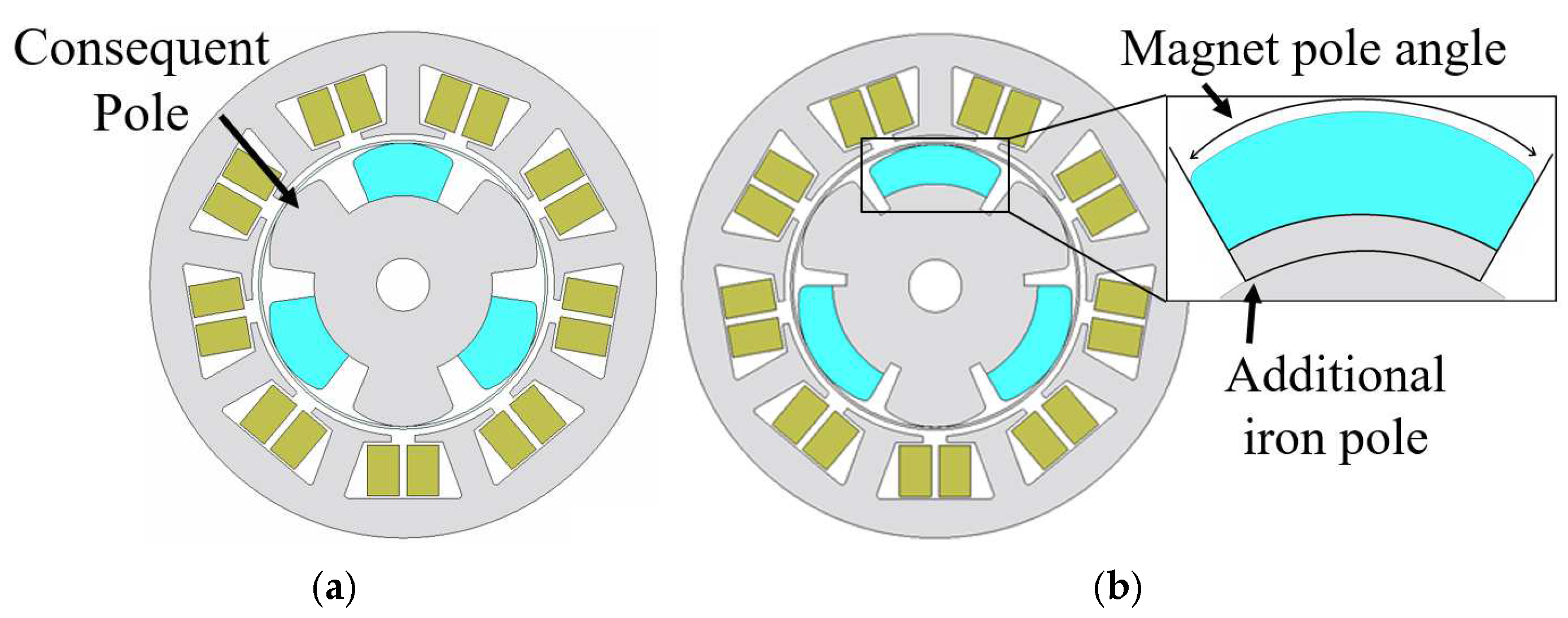
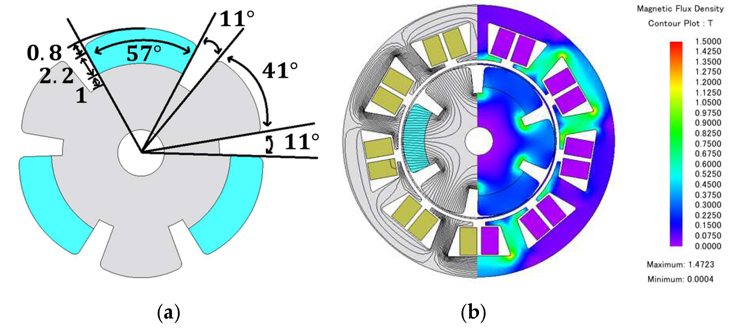
2.1. Design of Conventional CPM and Proposed CPM
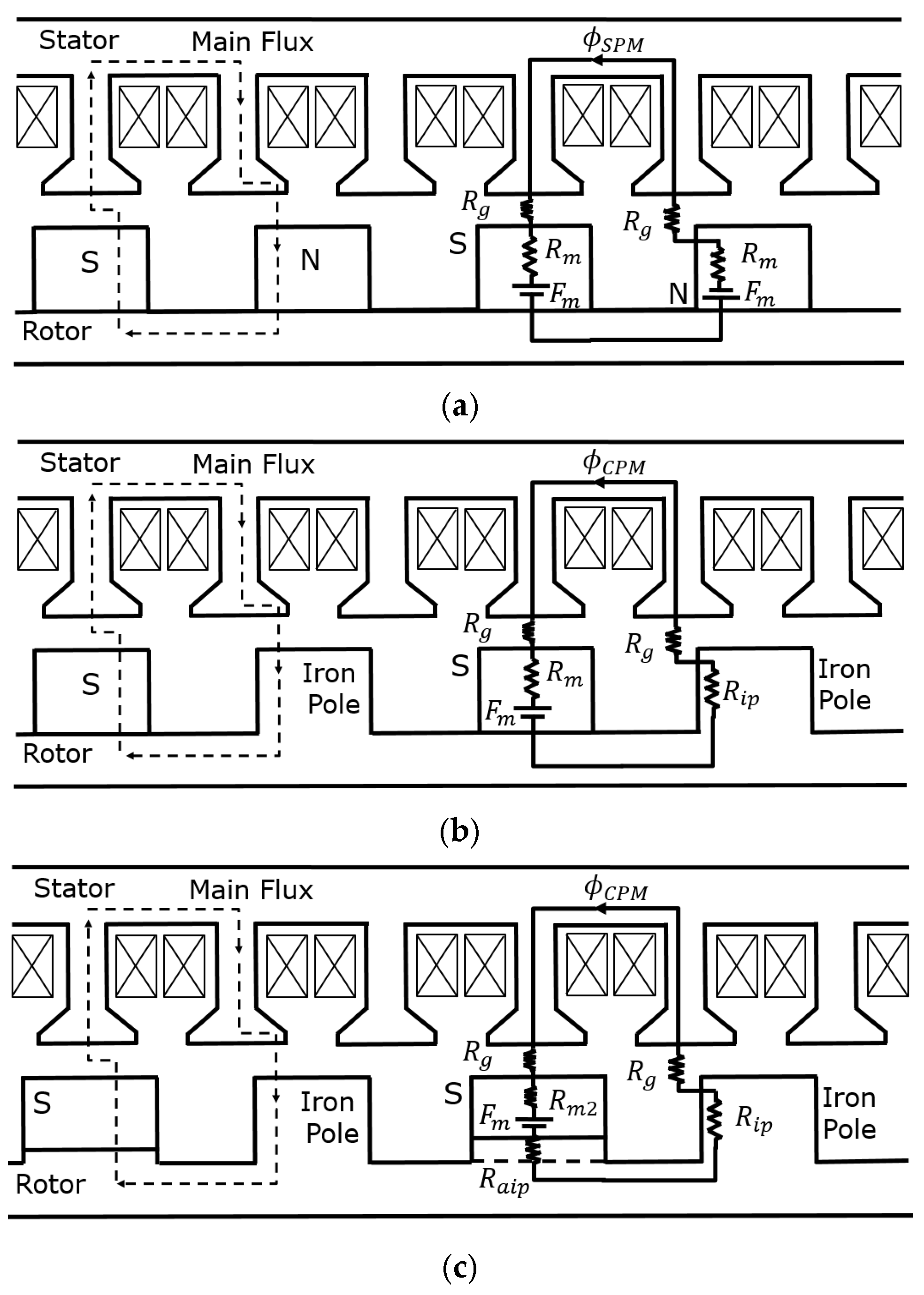
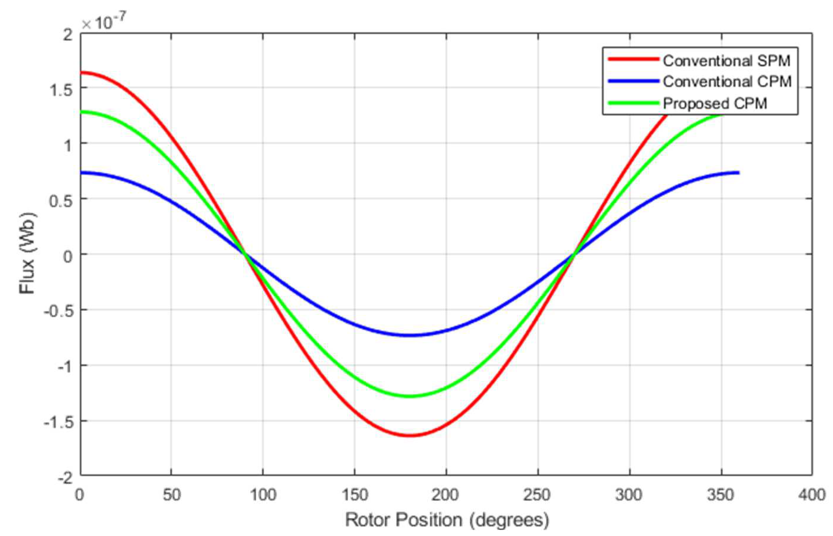
2.2. Analytical Comparison of Magnetic Flux
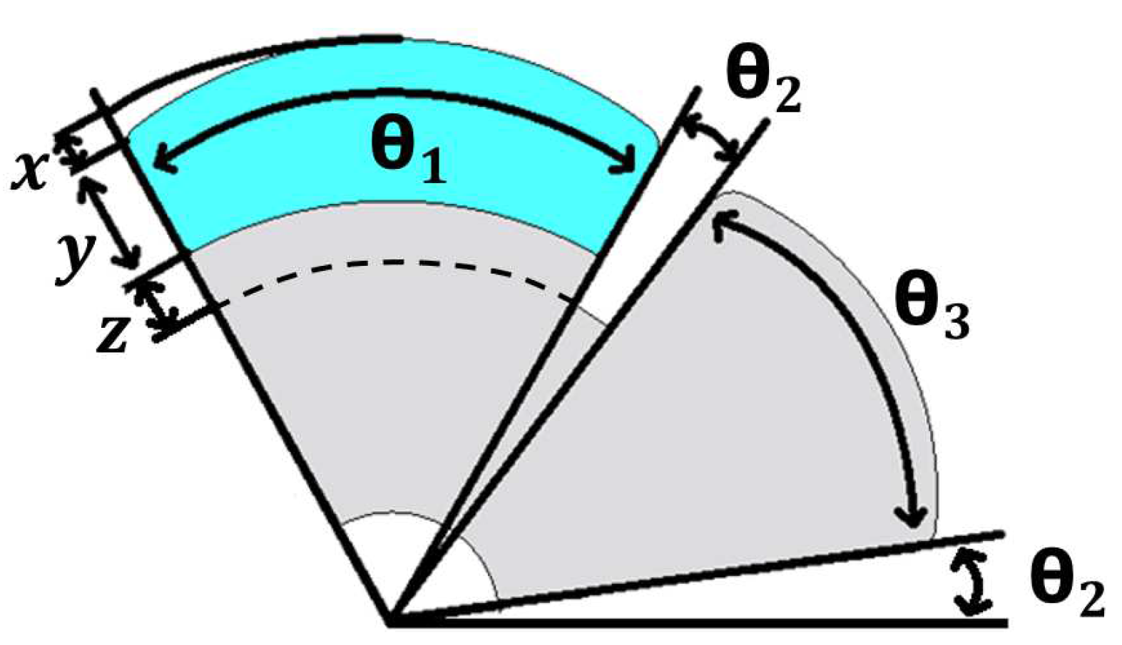
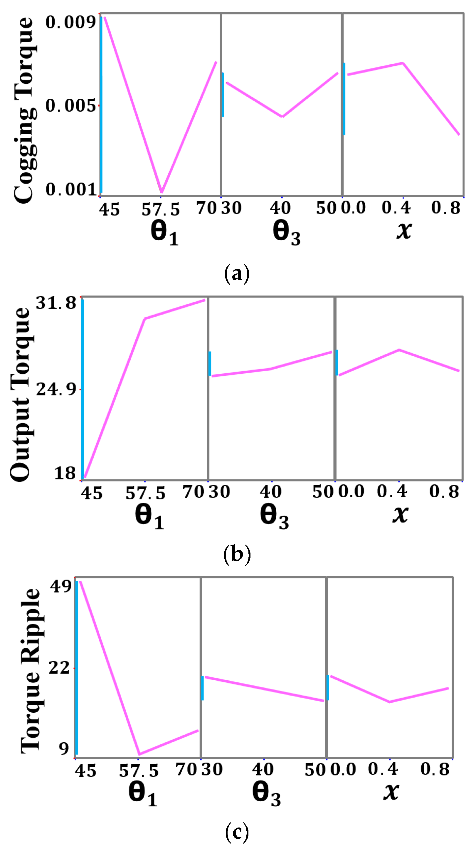
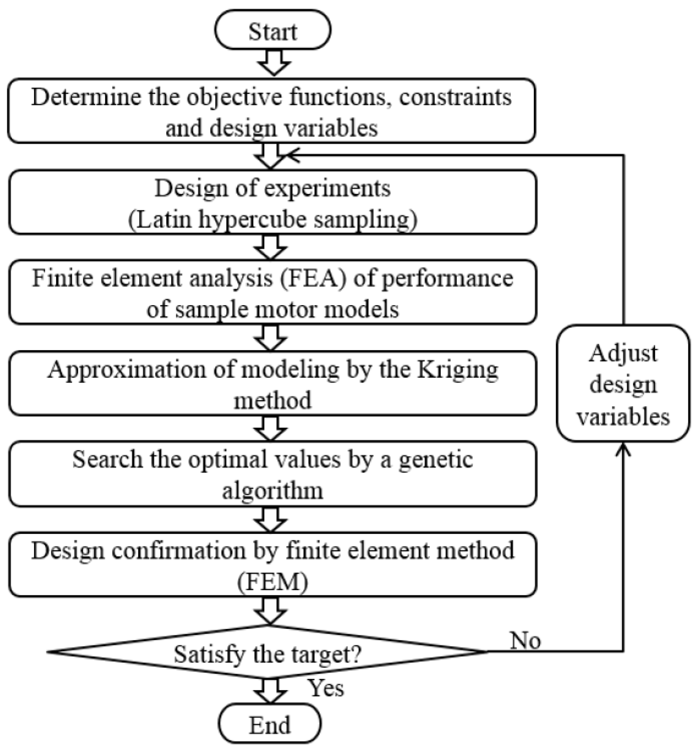
3. Optimal Design of Proposed CPM
- (1)
- =
- (2)
- θ1 + 2 × θ2 + θ3 = 120°
- (3)
- 45° ≤ θ1 ≤ 65°, 30°≤ θ3 ≤ 45°
- (4)
- x + y + z = 4 mm
- (5)
- 0 ≤ x ≤ 0.8 mm, with z depending on θ1
4. Comparison of Conventional and Proposed Machines
5. Conclusions
Author Contributions
Funding
Data Availability Statement
Conflicts of Interest
References
- Yoon, G.Y.; You, Y.M. Optimal Design of a Novel Consequent-Pole Interior Permanent Magnet Motor with Flared-Structured Rotor. Appl. Sci. 2024, 14, 1496. [Google Scholar] [CrossRef]
- Onsal, M.; Cumhur, B.; Demir, Y.; Yolacan, E.; Aydin, M. Rotor Design Optimization of a New Flux-Assisted Consequent Pole Spoke-Type Permanent Magnet Torque Motor for Low-Speed Applications. IEEE Trans. Magn. 2018, 54, 8206005. [Google Scholar] [CrossRef]
- Chung, S.U.; Kim, J.W.; Chun, Y.D.; Woo, B.C.; Hong, D.K. Fractional Slot Concentrated Winding PMSM With Consequent Pole Rotor for a Low-Speed Direct Drive: Reduction of Rare Earth Permanent Magnet. IEEE Trans. Energy Convers. 2015, 30, 103–109. [Google Scholar] [CrossRef]
- Jo, C.; Yun, I.; Hong, H.; Lee, J.; Kim, H.W. Asymmetric Design of Consequent Pole to Reduce Torque Ripple. IEEE Trans. Magn. 2024, 60, 8204905. [Google Scholar] [CrossRef]
- Wu, F.; Wang, X.; Bao, X.; Li, R. Design and analysis of a less-magnets consequent-pole line-start permanent magnet motor with low cogging torque. IET Power Appl. 2024, 18, 941–951. [Google Scholar] [CrossRef]
- Liu, Y.; Ma, K.; Gao, H.; Zhang, Z. Design and Performance Optimization of Flux-Focusing PMSMs With Consequent-Pole Rotor Considering PM Utilization Ratio. IEEE Trans. Ind. Electron. 2024, 71, 8503–8513. [Google Scholar] [CrossRef]
- Guo, L.; Yu, H.; Wang, H. Design and Optimization of External Rotor Consequent Pole Permanent Magnet Motor with Low Iron Loss and Low Torque Ripple. World Electr. Veh. J. 2024, 15, 232. [Google Scholar] [CrossRef]
- Zhang, Z.; Zhang, M.; Yin, J.; Wu, J.; Yang, C. An Analytical Method for Calculating the Cogging Torque of a Consequent Pole Hybrid Excitation Synchronous Machine. Energies 2022, 15, 878. [Google Scholar] [CrossRef]
- Li, F.; Wang, K.; Li, J.; Sun, H.Y. Electromagnetic Performance Analysis of Consequent-Pole PM Machine with Asymmetric Magnetic Pole. IEEE Trans. Magn. 2019, 55, 8103205. [Google Scholar] [CrossRef]
- Li, J.; Wang, K.; Liu, C.; Xu, B.F. Elimination of Unipolar Leakage Flux in Consequent Pole PM Machines by Employing Novel Pole Sequence. IEEE Trans. Magn. 2018, 54, 8106105. [Google Scholar] [CrossRef]
- Xu, G.; Zhao, W.; Liu, G.; Zhai, F.; Chen, Q. Torque Performance Improvement of Consequent-Pole PM Motors with Hybrid Rotor Configuration. IEEE Trans. Transp. Electrif. 2021, 7, 1561–1572. [Google Scholar] [CrossRef]
- Tu, R.; Yang, H.; Lin, H.; Zhan, H.; Wu, D.; Yu, M.; Chen, L.; Chen, W. Investigation of a Novel Consequent-Pole Flux-Intensifying Memory Machine. Energies 2022, 15, 5501. [Google Scholar] [CrossRef]
- Akihisa, H.; Noguchi, T.; Murakami, K. Mathematical Model Derivation and Experimental Verification of Novel Consequent-Pole Adjustable Speed PM Motor. Energies 2022, 15, 6147. [Google Scholar] [CrossRef]
- Li, J.; Wang, K.; Zhang, H. Flux-Focusing Permanent Magnet Machines with Modular Consequent Pole Rotor. IEEE Trans. Ind. Electron. 2020, 67, 3374–3385. [Google Scholar] [CrossRef]
- Dajaku, G. Comparison Study of Permanent Magnet Synchronous Machines with Consequent Pole and HUPM Rotor. IEEE Trans. Magn. 2022, 58, 8104110. [Google Scholar] [CrossRef]
- Li, J.; Huang, X.; Zhou, B.; Liu, Y.; Wang, Z. Research on Segmented Primary Consequent-Pole Permanent Magnet Linear Synchronous Motor with Symmetric and Periodic End Force. Symmetry 2021, 13, 2374. [Google Scholar] [CrossRef]
- Zhang, L.; Liu, X.; Ouyang, X.; Chen, W. Characteristic Analysis of Conventional Pole and Consequent Pole IPMSM for Electric Vehicle Applications. Energy Rep. 2022, 8, 259–269. [Google Scholar] [CrossRef]
- Guo, L.; Li, Q.; Wang, H. Design and Analysis of Consequent Pole Permanent Magnet Synchronous Motor with Low Torque Ripple. IET Electr. Power Appl. 2022, 17, 547–561. [Google Scholar] [CrossRef]
- Li, J.; Wang, K. A Novel Spoke-Type PM Machine Employing Asymmetric Modular Consequent-Pole Rotor. IEEE/ASME Trans. Mechatron. 2019, 24, 2182–2192. [Google Scholar] [CrossRef]
- Li, Y.; Zhou, Q.; Ding, S.; Li, W.; Hang, J. Design and Evaluation of Reduced-Rare-Earth Interior Consequent-Pole Permanent Magnet Machines for Automotive Applications. IEEE Trans. Ind. Appl. 2023, 59, 1372–1382. [Google Scholar] [CrossRef]
- Li, J.; Wang, K. Analytical Determination of Optimal PM Arc Ratio of Consequent Pole Permanent Magnet Machines. IEEE/ASME Trans. Mechatron. 2018, 23, 2168–2177. [Google Scholar] [CrossRef]
- Zhang, G.; Hou, P. Optimization Design of Cogging Torque for Electric Power Steering Motors. Machines 2024, 12, 517. [Google Scholar] [CrossRef]
- Hwang, K.Y.; Yun, K.Y.; Song, B.K. System-level Fault Tolerance Design Process of Dual-winding Motors for Overheat in Integrated Electric Braking System of Autonomous Vehicle. IEEE Trans. Veh. Technol. 2023, 72, 3063–3073. [Google Scholar] [CrossRef]
- Hwang, K.Y.; Oh, S.Y.; Park, E.K.; Song, B.K.; Kim, S.I. Thermal Fault-Tolerant Asymmetric Dual-Winding Motors in Integrated Electric Braking System for Autonomous Vehicles. Machines 2024, 12, 708. [Google Scholar] [CrossRef]
- Hwang, K.Y.; Yun, K.Y. Fault Tolerant Design Process of Spoke type IPM Motor Considering Irreversible Demagnetization of PM in Integrated Electric Brake System. IEEE Trans. Magn. 2022, 58, 8206809. [Google Scholar] [CrossRef]


| Item | Unit | Value |
|---|---|---|
| SPM | ||
| Air gap | mm | 0.5 |
| Stack length | mm | 30 |
| Rotor diameter | mm | 21.9 |
| Stator diameter | mm | 38.4 |
| Magnet thickness | mm | 4 |
| Number of turns | - | 31 |
| Slot fill factor | % | 30 |
| Rated current/phase | Arms | 1.4 |
| Rated power | W | 12 |
| Rated speed | RPM | 3500 |
| PM material | T | Br = 0.4 (Ferrite) |
| Core material | - | 50H1300 (by NSSMC) |
| Item | Unit | Value | ||
|---|---|---|---|---|
| Conventional SPM | Conventional CPM | Proposed CPM | ||
| Air gap | mm | 0.5 | 0.5 | 0.5 |
| Stack length | mm | 30 | 30 | 30 |
| Rotor diameter | mm | 21.9 | 21.9 | 21.9 |
| Stator diameter | mm | 38.4 | 38.4 | 38.4 |
| Magnet thickness | mm | 4 | 4 | 3 |
| Number of turns | - | 31 | 31 | 31 |
| Slot fill factor | % | 30 | 30 | 30 |
| Rated current | Arms | 1.4 | 1.4 | 1.4 |
| Rated power | W | 12 | 12 | 12 |
| Rated speed | RPM | 3500 | 3500 | 3500 |
| PM material | T | Br = 0.4 (Ferrite) | ||
| Core material | - | 50H1300 (by NSSMC) | ||
| Item | Unit | Value | ||
|---|---|---|---|---|
| Conventional SPM | Conventional CPM | Proposed CPM | ||
| Back EMF | V | 4.04 | 3.2 | 3.81 |
| THD | % | 5.2 | 22.9 | 3.35 |
| Cogging torque | mNm | 2.13 | 4.88 | 1.57 |
| Torque | mNm | 32.9 | 26.2 | 30.9 |
| Torque ripple | % | 13.2 | 49 | 12.3 |
| Magnet volume | mm3 | 5397 | 2698.5 | 2698.5 |
| Torque per magnet volume | ||||
| Conventional SPM | Conventional CPM | Proposed CPM | |||||||||
|---|---|---|---|---|---|---|---|---|---|---|---|
[mNm] | [rpm] | [A] | [%] | [mNm] | [rpm] | [A] | [%] | [mNm] | [rpm] | [A] | [%] |
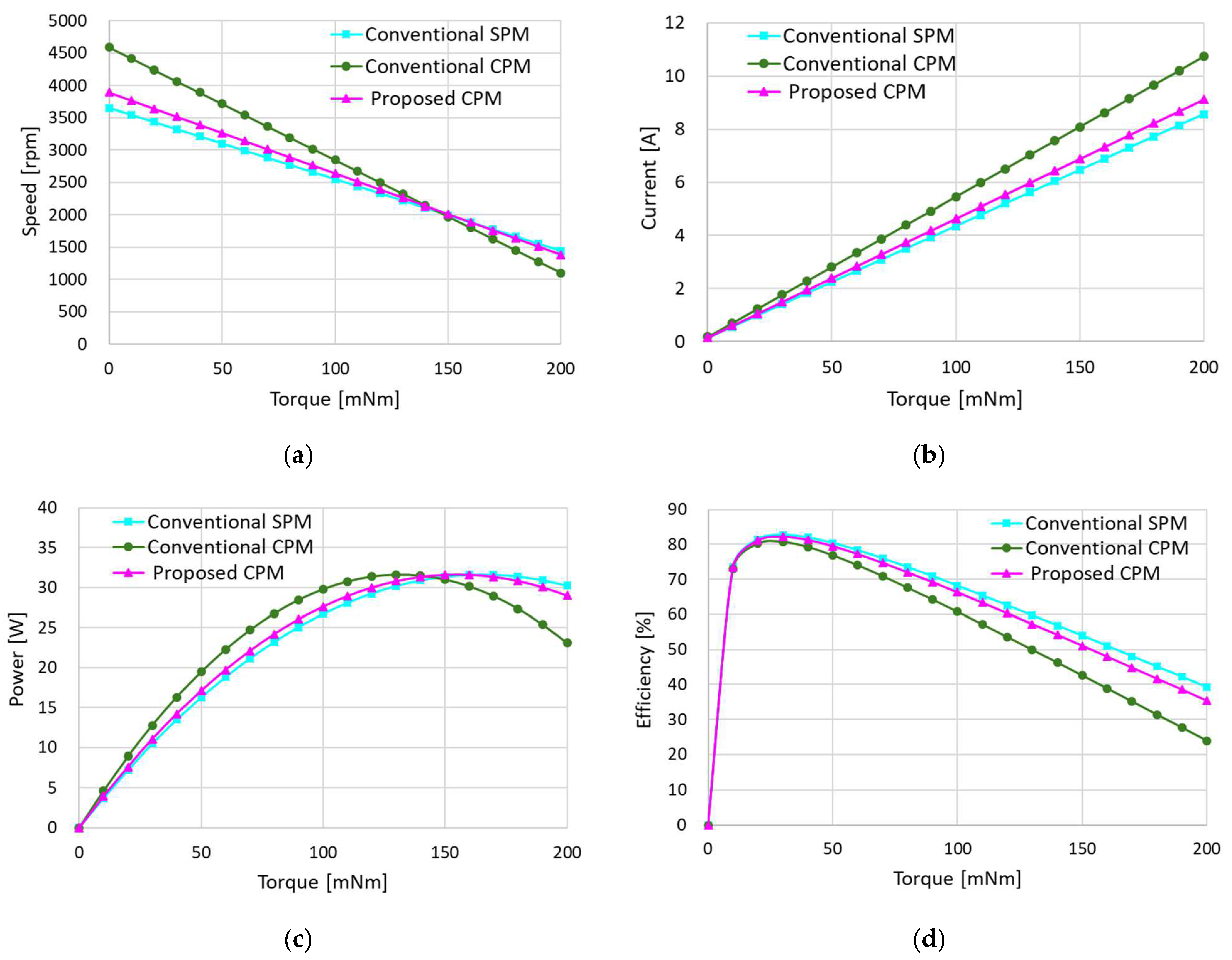
| 0 | 3657 | 0.14 | 0.0 | 0 | 4592 | 0.18 | 0.0 | 0 | 3894 | 0.15 | 0.0 |
| 10 | 3547 | 0.56 | 73.5 | 10 | 4418 | 0.70 | 73.1 | 10 | 3768 | 0.60 | 73.4 |
| 20 | 3436 | 0.98 | 81.4 | 20 | 4243 | 1.23 | 80.2 | 20 | 3643 | 1.05 | 81.1 |
| 30 | 3325 | 1.40 | 82.7 | 30 | 4069 | 1.76 | 80.8 | 30 | 3518 | 1.49 | 82.2 |
| 40 | 3215 | 1.83 | 82.0 | 40 | 3894 | 2.29 | 79.3 | 40 | 3392 | 1.94 | 81.3 |
| 50 | 3104 | 2.25 | 80.4 | 50 | 3720 | 2.81 | 76.9 | 50 | 3267 | 2.39 | 79.5 |
| 60 | 2993 | 2.67 | 78.3 | 60 | 3545 | 3.34 | 74.1 | 60 | 3141 | 2.84 | 77.3 |
| 70 | 2883 | 3.09 | 76.0 | 70 | 3371 | 3.87 | 71.0 | 70 | 3016 | 3.29 | 74.7 |
| 80 | 2772 | 3.51 | 73.5 | 80 | 3196 | 4.40 | 67.7 | 80 | 2890 | 3.74 | 72.0 |
| 90 | 2661 | 3.93 | 70.9 | 90 | 3022 | 4.92 | 64.3 | 90 | 2765 | 4.18 | 69.2 |
| 100 | 2551 | 4.35 | 68.2 | 100 | 2847 | 5.45 | 60.8 | 100 | 2639 | 4.63 | 66.3 |
| 110 | 2440 | 4.77 | 65.4 | 110 | 2673 | 5.98 | 57.2 | 110 | 2514 | 5.08 | 63.3 |
| 120 | 2329 | 5.20 | 62.6 | 120 | 2498 | 6.51 | 53.6 | 120 | 2388 | 5.53 | 60.3 |
| 130 | 2219 | 5.62 | 59.7 | 130 | 2324 | 7.04 | 50.0 | 130 | 2263 | 5.98 | 57.3 |
| 140 | 2108 | 6.04 | 56.9 | 140 | 2149 | 7.56 | 46.3 | 140 | 2138 | 6.42 | 54.2 |
| 150 | 1997 | 6.46 | 54.0 | 150 | 1975 | 8.09 | 42.6 | 150 | 2012 | 6.87 | 51.1 |
| 160 | 1887 | 6.88 | 51.0 | 160 | 1800 | 8.62 | 38.9 | 160 | 1887 | 7.32 | 48.0 |
| 170 | 1776 | 7.30 | 48.1 | 170 | 1626 | 9.15 | 35.2 | 170 | 1761 | 7.77 | 44.8 |
| 180 | 1665 | 7.72 | 45.2 | 180 | 1451 | 9.67 | 31.4 | 180 | 1636 | 8.22 | 41.7 |
| 190 | 1555 | 8.14 | 42.2 | 190 | 1277 | 10.20 | 27.7 | 190 | 1510 | 8.67 | 38.5 |
| 200 | 1444 | 8.57 | 39.2 | 200 | 1102 | 10.73 | 23.9 | 200 | 1385 | 9.11 | 35.4 |
Disclaimer/Publisher’s Note: The statements, opinions and data contained in all publications are solely those of the individual author(s) and contributor(s) and not of MDPI and/or the editor(s). MDPI and/or the editor(s) disclaim responsibility for any injury to people or property resulting from any ideas, methods, instructions or products referred to in the content. |
© 2024 by the authors. Licensee MDPI, Basel, Switzerland. This article is an open access article distributed under the terms and conditions of the Creative Commons Attribution (CC BY) license (https://creativecommons.org/licenses/by/4.0/).
Share and Cite
Jo, S.-J.; Baek, S.-W.; Hwang, K.-Y. Optimization Design of Novel Consequent Pole Motor for Electric Power Steering System. Machines 2024, 12, 893. https://doi.org/10.3390/machines12120893
Jo S-J, Baek S-W, Hwang K-Y. Optimization Design of Novel Consequent Pole Motor for Electric Power Steering System. Machines. 2024; 12(12):893. https://doi.org/10.3390/machines12120893
Chicago/Turabian StyleJo, Sung-Jun, Soo-Whang Baek, and Kyu-Yun Hwang. 2024. "Optimization Design of Novel Consequent Pole Motor for Electric Power Steering System" Machines 12, no. 12: 893. https://doi.org/10.3390/machines12120893
APA StyleJo, S.-J., Baek, S.-W., & Hwang, K.-Y. (2024). Optimization Design of Novel Consequent Pole Motor for Electric Power Steering System. Machines, 12(12), 893. https://doi.org/10.3390/machines12120893