1. Introduction
Slewing bearings play a vital role in heavy-duty mechanical transmission systems. They can withstand axial loads, radial loads, and overturning moments simultaneously. They are widely used in lifting equipment, metallurgical machinery, and aerospace technology. In recent years, many scholars have used the finite element method to study the comprehensive performance of slewing bearings [
1].
In recent years, scholars have established finite element models of bearings, including rolling elements and rings, to study bearing performance. He et al. [
2] established a finite element model of a slewing bearing and acquired the contact stresses between balls and raceways for analyzing fatigue life, and the accuracy of simulation results was verified by experiments. Porziani et al. [
3] replaced the rolling element array with a toroid-shaped element when establishing a finite element model of a four-point contact slewing bearing.
Not only did this approach simplify the computational burden, but it also obtained highly accurate simulation results. He et al. [
4] established a finite element model of a single-row ball slewing bearing and investigated the effect of mesh size on the finite element analysis of the load capacity of the bearing, and the accuracy and efficiency were demonstrated in this study. Martín et al. [
5] established a finite element model of a crossed roller wire race bearing and investigated the effect of geometric dimensions on the bearing load capacity under an axial load. Martín et al. [
6] introduced a simplified sub-model to simulate complex contact among rolling elements, wires, and raceways, with a high consistency between the simplified and original results. Skyba et al. [
7] established a finite element model of a slewing bearing and analyzed bearing stiffness, and the results were consistent with the theory.
Due to much contact between the rolling elements and the bearing rings, computation has become quite complicated. To address this problem, Matthis et al. [
8] replaced the ball–raceway contact with nonlinear spring elements when establishing a finite element model of double-row four-point contact ball bearings, and experiments proved that the method is correct. He [
9] and Liu et al. [
10] replaced the ball–raceway contact with nonlinear spring elements when establishing a finite element model of a four-point contact slewing bearing, and the results were consistent with the theory. He et al. [
11] replaced the ball–raceway contact with nonlinear spring elements when establishing a finite element model of slewing bearings, and the results were consistent with the theory. Martín et al. [
12] proposed a method for establishing a finite element model of crossed roller wire race bearings, using CONBIN39 in ANSYS to replace the contact between the wire and both the rolling elements and the raceway. Li et al. [
13] replaced rolling elements with spring units when establishing a finite element model of double-row different-diameter ball slewing bearings, and the results showed that reducing the radius coefficient of the raceway and increasing the diameter of the rolling elements and the contact angle can improve the load capacity. Deng et al. [
14] replaced the contact between the rolling elements and the raceways with non-linear springs when establishing a finite element model of a slewing bearing. The obtained results, including the load distribution, ring stress, and contact stress, were consistent with the theory. Li et al. [
15] calculated the internal stress distribution of the bearing rings using the mixed finite element model with both solid and spring elements of the slewing bearing assembly. The results were consistent with the engineering practice for slewing bearings. He [
16] and Wang et al. [
17] replaced rolling elements with nonlinear springs when establishing a finite element model of three-row roller slewing bearings, and the results were consistent with the theory. Chen et al. [
18] established four finite element models of slewing bearings with different structures and replaced the contact between the rolling elements and the raceways with spring units; additionally, they studied the effects of the bolt number, bolt pre-tightening force, and other factors on the performance of slewing bearings. Smolnicki et al. [
19,
20] considered that the contact between the rolling elements and raceways should be replaced with nonlinear springs when researching slewing bearings, and the results had good accuracy.
The use of spring units has greatly improved the efficiency of calculation. Furthermore, several researchers have replaced other units to study the complex contact between rolling elements and raceways. Heras et al. [
21] used a cage-like structure composed of beam units to simulate the contact between rolling elements and raceways when establishing a finite element model of a slewing bearing, and the results were consistent with the theory. Duval et al. [
22] replaced the contact between rolling elements and raceways with beam units when establishing a finite element model of a slewing bearing and performed fatigue analysis on the bearing, and the results were consistent with the theory. Kunc et al. [
23] used bar units to simulate the contact between rolling elements and raceways in their finite element model of a slewing bearing. The results indicate that the method is correct. Alain et al. [
24] proposed that a rolling element should be replaced with two nonlinear spring units and eight rigid bar units, and the method can simulate the changes in the contact load and contact angle of rolling elements. Chen et al. [
25] replaced a rolling element with eight rigid bar units and two nonlinear spring units when establishing a finite element model of slewing bearings. Kania et al. [
26] replaced the rolling elements and the connecting bolts with bar units and beam units when establishing a finite element model of a three-row cylindrical roller slewing bearing and obtained the load distribution of the rolling elements.
However, the majority of current researchers examining slewing bearings are primarily concerned with the performance of the rolling elements, paying little attention to the performance of the bolt. They also exclude the bolts while modeling, just including the inner and outer rings, as well as the rolling portions. Only a few academics, including Kania and Chen, have created finite element models using bolts. Instead of evaluating the bolts’ comprehensive performance, they model them for more accurate results.
The inner and outer rings, as well as the upper and lower supports, are connected by bolts, so it is also necessary to establish an integrated model of slewing bearings that includes the rings, the rolling elements, and the bolts for studying their performance.
Furthermore, the majority of the papers investigate the effect of conventional load parameters such as the radial load, axial load, and overturning moment, with few studies on structural parameters such as the number of rolling elements and bolts, as well as load parameters such as the contact angle, bolt preload, and the angle between radial load and overturning moment.
Therefore, in this paper, the QU2500.50 single-row four-point contact ball slewing bearing is taken as the research object. The bearing support bolt-integrated finite element model is established by HyperMesh 2021 and ANSYS 2022 R1, and its accuracy is theoretically verified. Then, the effects of the rolling element number, contact angle, bolt number, bolt pre-tightening force coefficient, and the angle between the radial load and overturning moment on the comprehensive performance of the bearings and the connecting bolts are investigated, respectively.
3. Influence of Each Parameter on the Performance of Bearings and Bolts
3.1. Influence of the Rolling Element Number Z
The maximum deformation curves of slewing bearings, inner and outer rings, rolling elements, and bolts with different numbers of rolling elements (
Z) are shown in
Figure 10. From the diagram, it can be seen that as
Z increases, the maximum deformation of the slewing bearing, inner and outer rings, rolling elements, and bolts gradually decreases. When
Z increases from 60 to 140, the maximum deformation of the upper support decreases from 0.988 mm to 0.692 mm, the maximum deformation of the inner ring decreases from 0.708 mm to 0.453 mm, the maximum deformation of the rolling elements decreases from 0.436 mm to 0.287 mm, and the maximum deformation of the bolts decreases from 0.692 mm to 0.464 mm, representing decreases of 29.96%, 36.02%, 34.17%, and 32.95%, respectively.
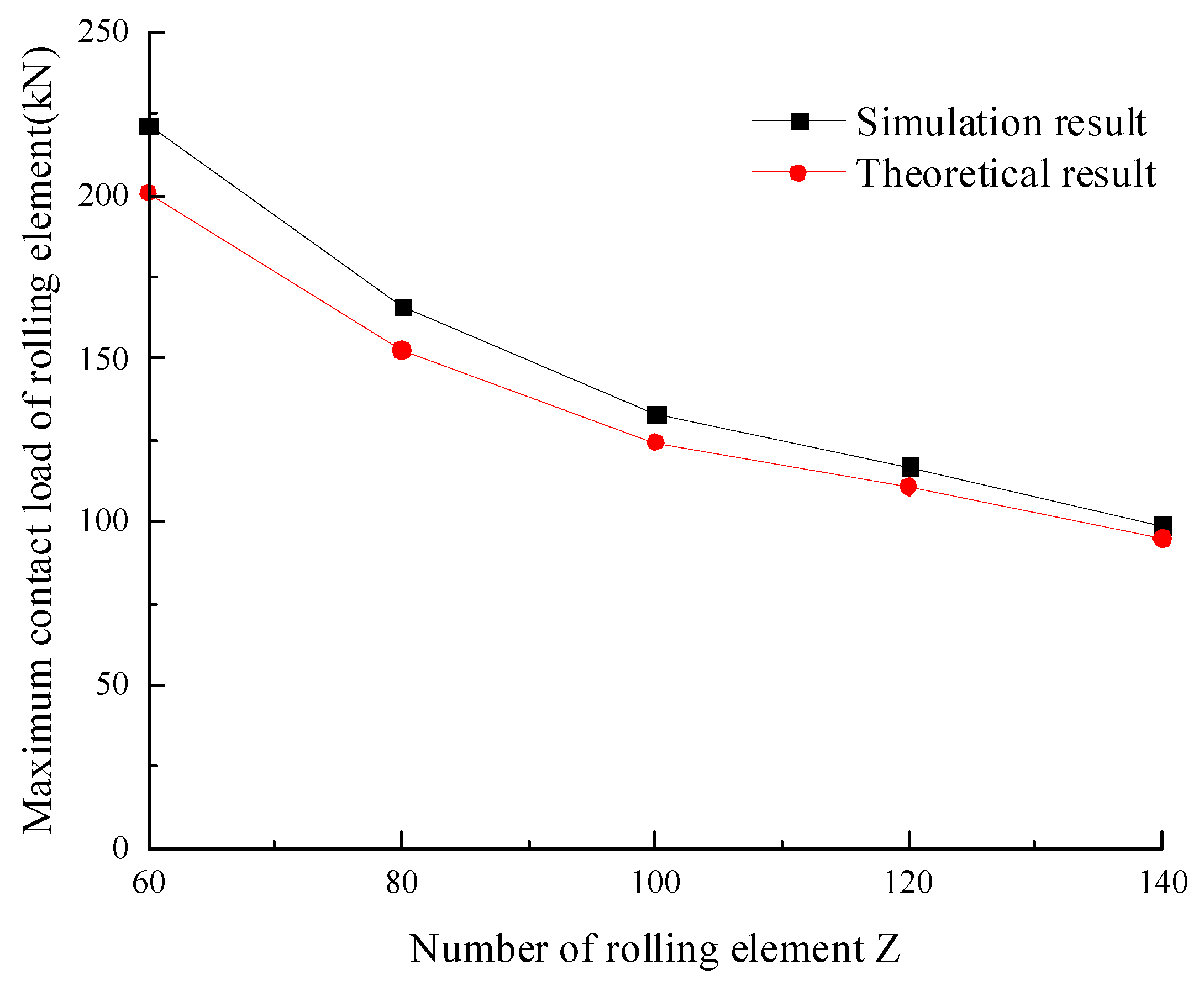
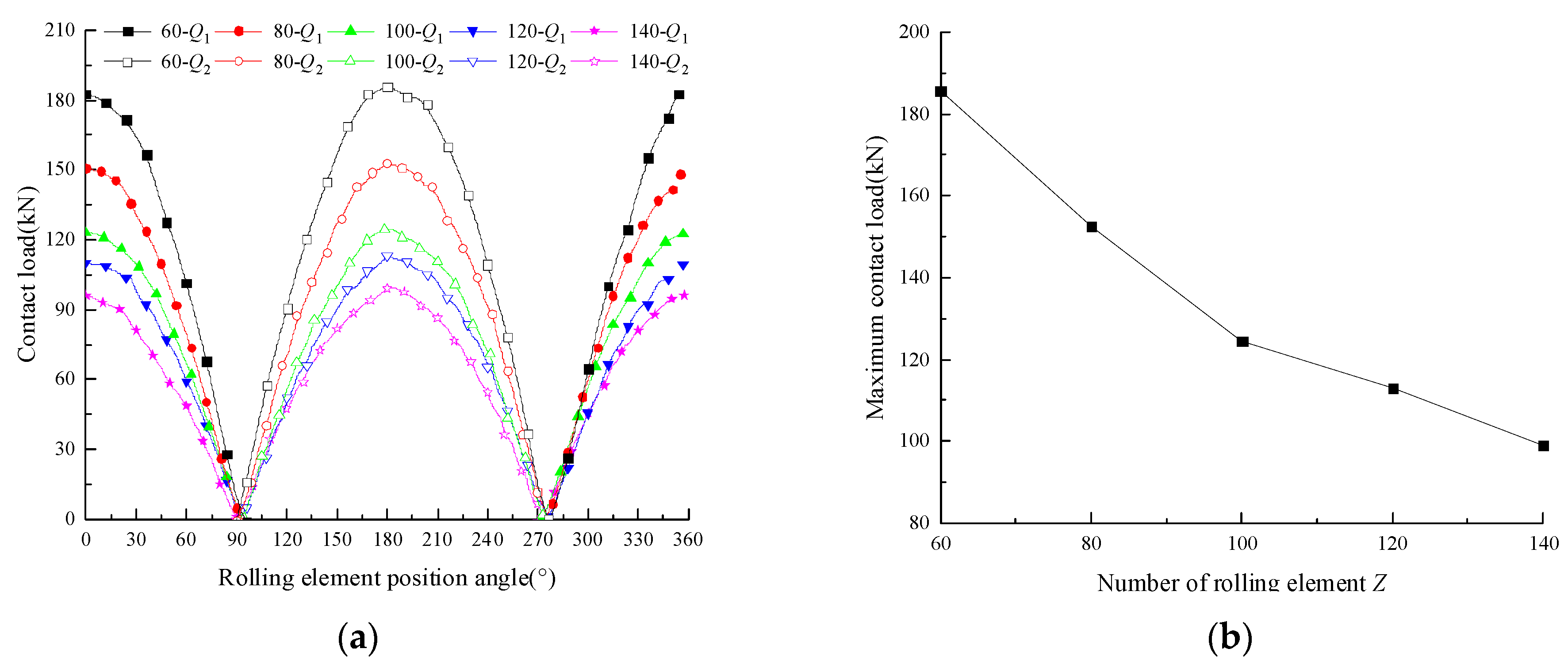
The contact load distribution curves of the rolling element and the maximum contact load curve of the rolling element with different
Z values are shown in
Figure 11. From the diagram, it can be seen that the load distribution with different
Z values is a cosine curve, and the contact load reaches the maximum when the position angle of the rolling element is 180°. The maximum contact load of the rolling element decreases gradually with the increase in
Z. When
Z increases from 60 to 140, the maximum contact load of the rolling element gradually decreases from 185.63 kN to 99.1 kN, with a decrease of 46.63%. When
Z increases from 60 to 100, the contact load decreases sharply, while when
Z increases from 100 to 140, the contact load decreases slowly.
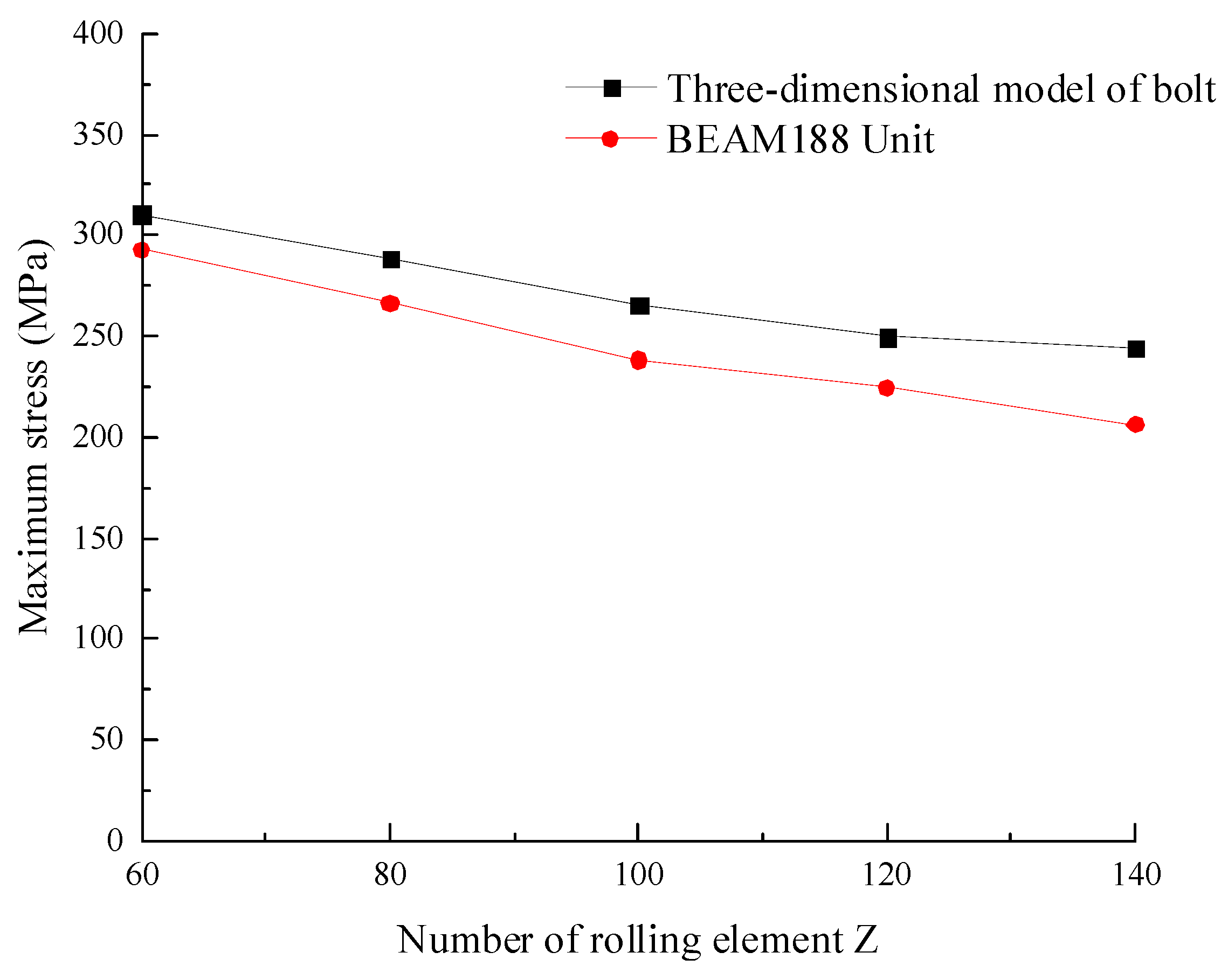
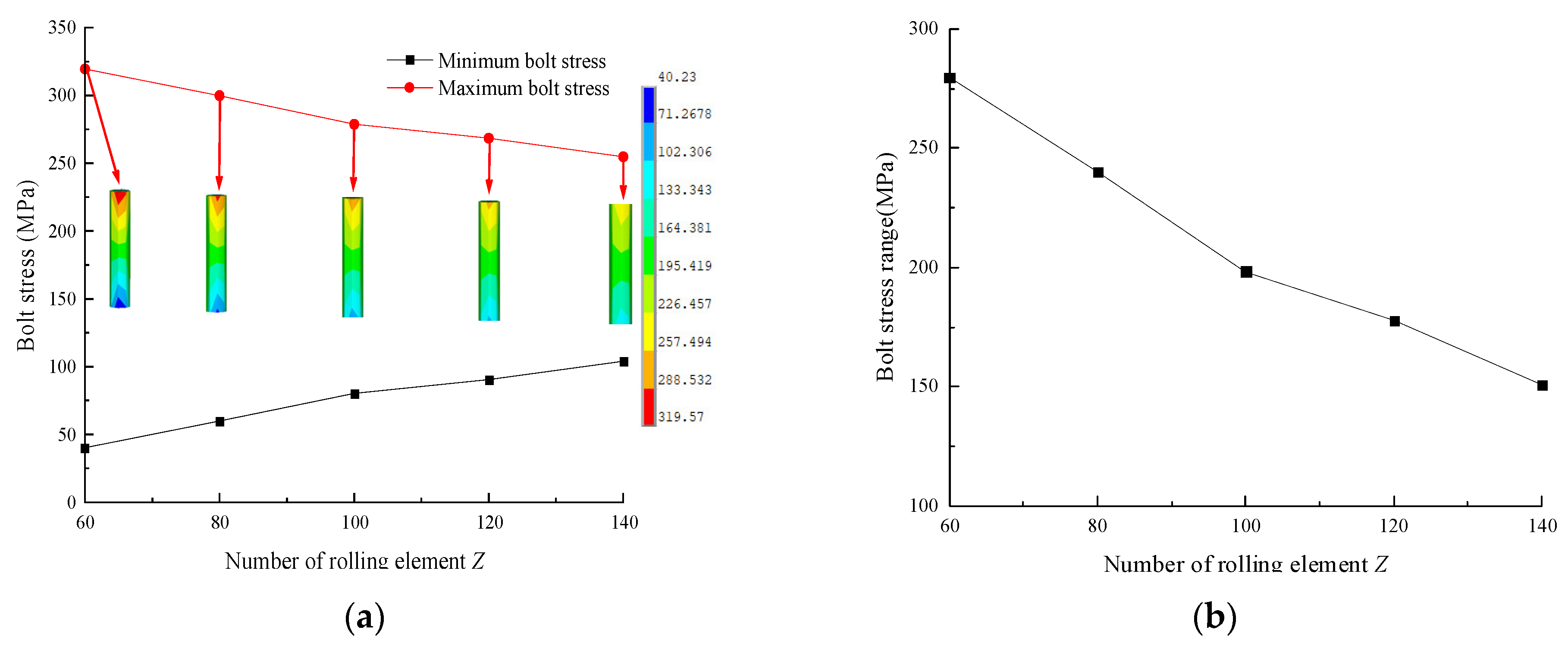
The maximum and minimum stress curves of the bolts at different
Z values and the stress range curve of the bolts are shown in
Figure 12. From the diagram, it can be seen that with an increase in
Z, the maximum stress of the bolt and the range of bolt stress decrease gradually, while the minimum stress of the bolt increases gradually, and they are linearly related to
Z. When
Z increases from 60 to 140, the maximum stress of the bolt decreases gradually from 319.57 MPa to 254.82 MPa, a decrease of 20.26%; the minimum stress increases gradually from 40.23 MPa to 104.02 MPa; and the bolt stress range decreases gradually from 279.34 MPa to 150.8 MPa, a decrease of 46.02%. These findings indicate that increasing
Z is beneficial for improving the uniformity of bolt stress distributions.
The reason why the bearing deformation, inner and outer ring deformation, rolling element deformation, rolling element contact load, maximum stress and minimum stress of bolts, and bolt stress range change with Z is because the increase in contact area between the rolling element and the raceway increases under the same external load conditions. The external load is borne by more rolling elements, so the load borne by each rolling element and bolt decreases. This causes the deformation of the slewing bearing, inner and outer rings, rolling elements, and bolts, and the contact load of the bolts and the maximum stress of the bolts are also reduced. Therefore, in the case of meeting the structural size, selecting a higher value of Z is beneficial for improving the bearing capacity of the slewing bearing and bolts.
3.2. Influence of Contact Angle α
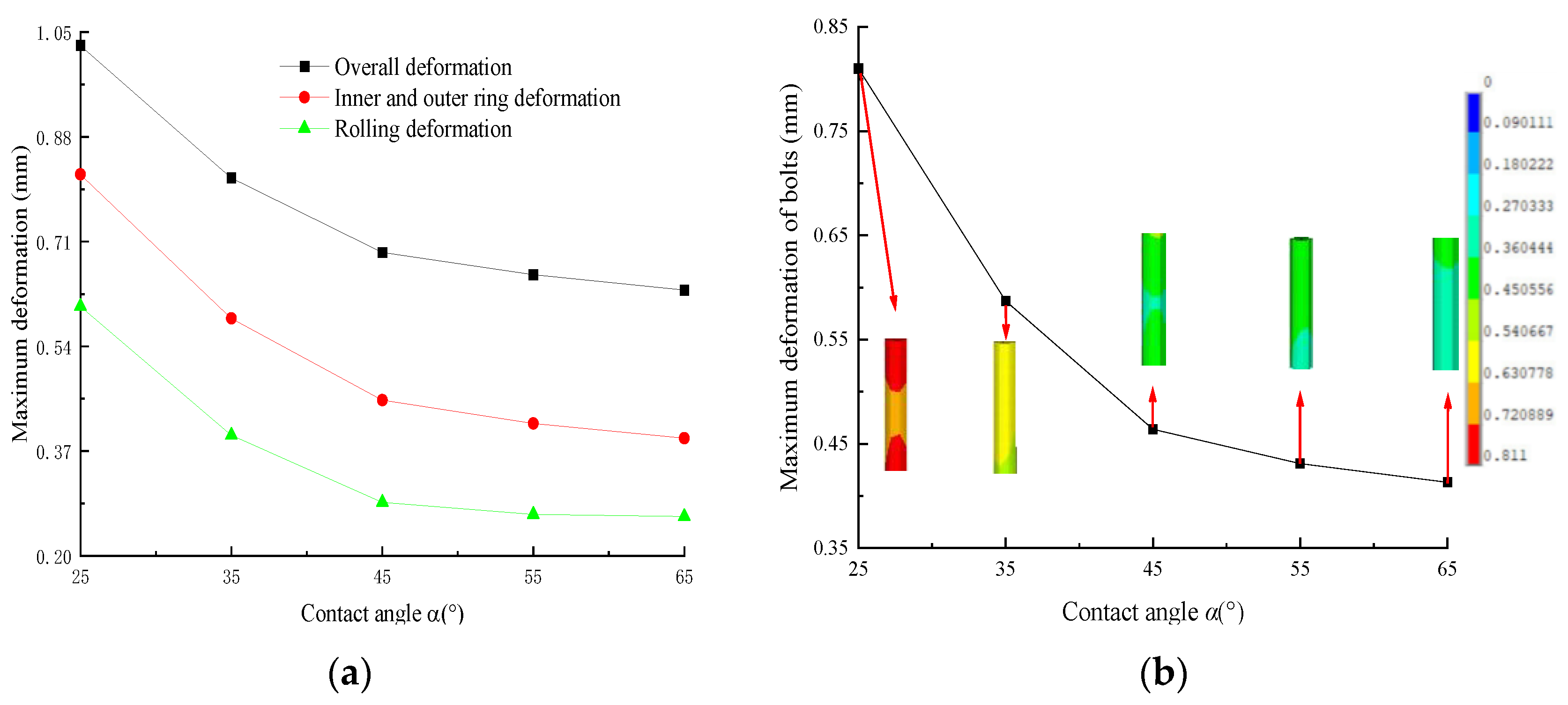
The maximum deformation curves of slewing bearings, inner and outer rings, rolling elements, and bolts with different values of contact angle
α are shown in
Figure 13. From the diagram, it can be seen that as
α increases, the maximum deformation of the slewing bearing, inner and outer rings, rolling elements, and bolts gradually decreases. When
α increases from 25° to 65°, the maximum deformation of the upper support decreases from 1.028 mm to 0.631 mm, the maximum deformation of the inner ring decreases from 0.819 mm to 0.391 mm, the maximum deformation of the rolling elements decreases from 0.605 mm to 0.264 mm, and the maximum deformation of the bolts decreases from 0.811 mm to 0.413 mm, representing decreases of 38.62%, 52.26%, 56.36%, and 49.08%, respectively.
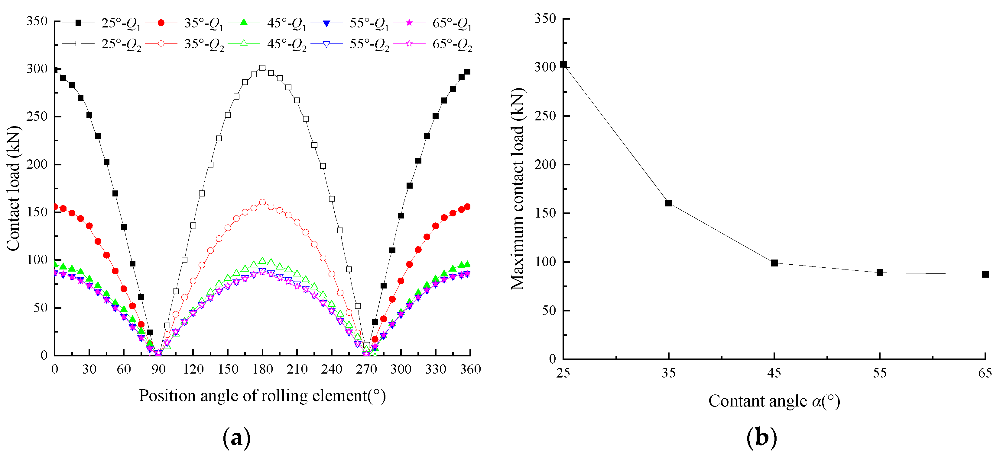
The contact load distribution curves of the rolling element and the maximum contact load curve of the rolling element with different α values are shown in
Figure 14. From the diagram, it can be seen that the load distribution with different
α values is a cosine curve, and the contact load reaches the maximum when the position angle of the rolling element is 180°. The maximum contact load of the rolling element decreases gradually with the increase in
α. When
α increases from 25° to 65°, the maximum contact load of the rolling element gradually decreases from 303.3 kN to 87.4 kN, a decrease of 71.20%. When
α increases from 25° to 45°, the contact load decreases sharply, while when
α increases from 45° to 65°, the contact load decreases slowly.
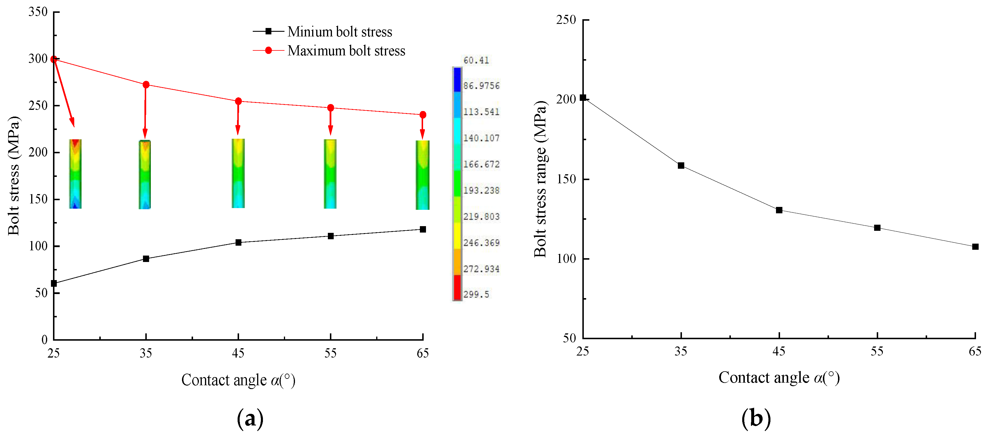
The maximum and minimum stress curves of the bolts and the stress range curve of bolts with different
α values are shown in
Figure 15. From the diagram, it can be seen that with the increase in
α, the maximum stress of the bolt and the range of bolt stress decrease gradually, while the minimum stress of the bolt increases gradually, and they are linearly related to
α. When α increases from 25° to 65°, the maximum stress of the bolt decreases gradually from 299.5 MPa to 240.32 MPa, a decrease of 19.76%; the minimum stress increases gradually from 60.41 MPa to 118.2 MPa; and the bolt stress range decreases gradually from 239.09 MPa to 122.12 MPa, a decrease of 48.92%. These findings indicate that increasing
α is beneficial for improving the uniformity of the bolt stress distribution.
The reason why the bearing deformation, inner and outer ring deformation, rolling element deformation, rolling element contact load, maximum stress and minimum stress of bolts, and bolt stress range change with α is because under the same external load conditions, as α increases, the axial bearing capacity of the bearing increases, so that the load on the rolling element gradually decreases, and then the deformation decreases. However, too-large α values cause the contact elliptical surface to exceed the edge of the raceway and the force on the raceway to increase sharply, resulting in the edge collapsing. Therefore, selecting the appropriate α value according to the load conditions of the slewing bearing is beneficial for improving the bearing capacity of the slewing bearing and bolts.
3.3. Influence of the Bolt Number N
The maximum deformation curves of slewing bearings, inner and outer rings, rolling elements, and bolts with different values of the bolt number,
N, are shown in
Figure 16. From the diagram, it can be seen that as
N increases, the maximum deformation of the slewing bearing, inner and outer rings, rolling elements, and bolts gradually decreases. When
N increases from 24 to 72, the maximum deformation of the upper support decreases from 1.195 mm to 0.535 mm, the maximum deformation of the inner ring decreases from 0.764 mm to 0.382 mm, the maximum deformation of the rolling elements decreases from 0.570 mm to 0.249 mm, and the maximum deformation of the bolts decreases from 0.906 mm to 0.393 mm, representing decreases of 55.23%, 50%, 56.32%, and 56.32%, respectively.
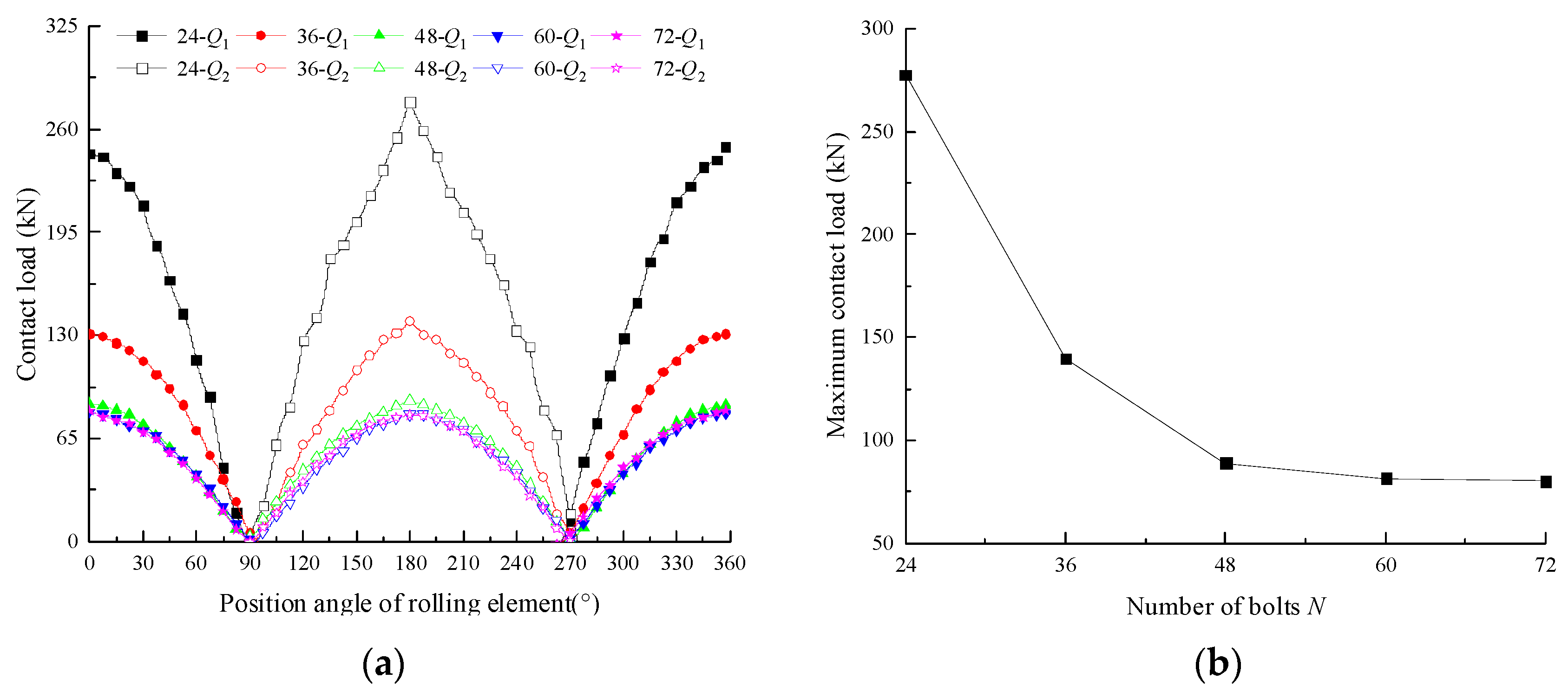
The contact load distribution curves of the rolling element and the maximum contact load curve of the rolling element with different
N values are shown in
Figure 17. From the diagram, it can be seen that the load distribution at different
N values is a cosine curve, and the contact load reaches the maximum when the position angle of the rolling element is 180°. The maximum contact load of the rolling element decreases gradually with the increase in
N. When
N increases from 24 to 72, the maximum contact load of the rolling element gradually decreases from 277.1 kN to 80.2 kN, a decrease of 71.03%. When
N increases from 24 to 48, the contact load decreases sharply, while when
N increases from 48 to 70, the contact load decreases slowly.
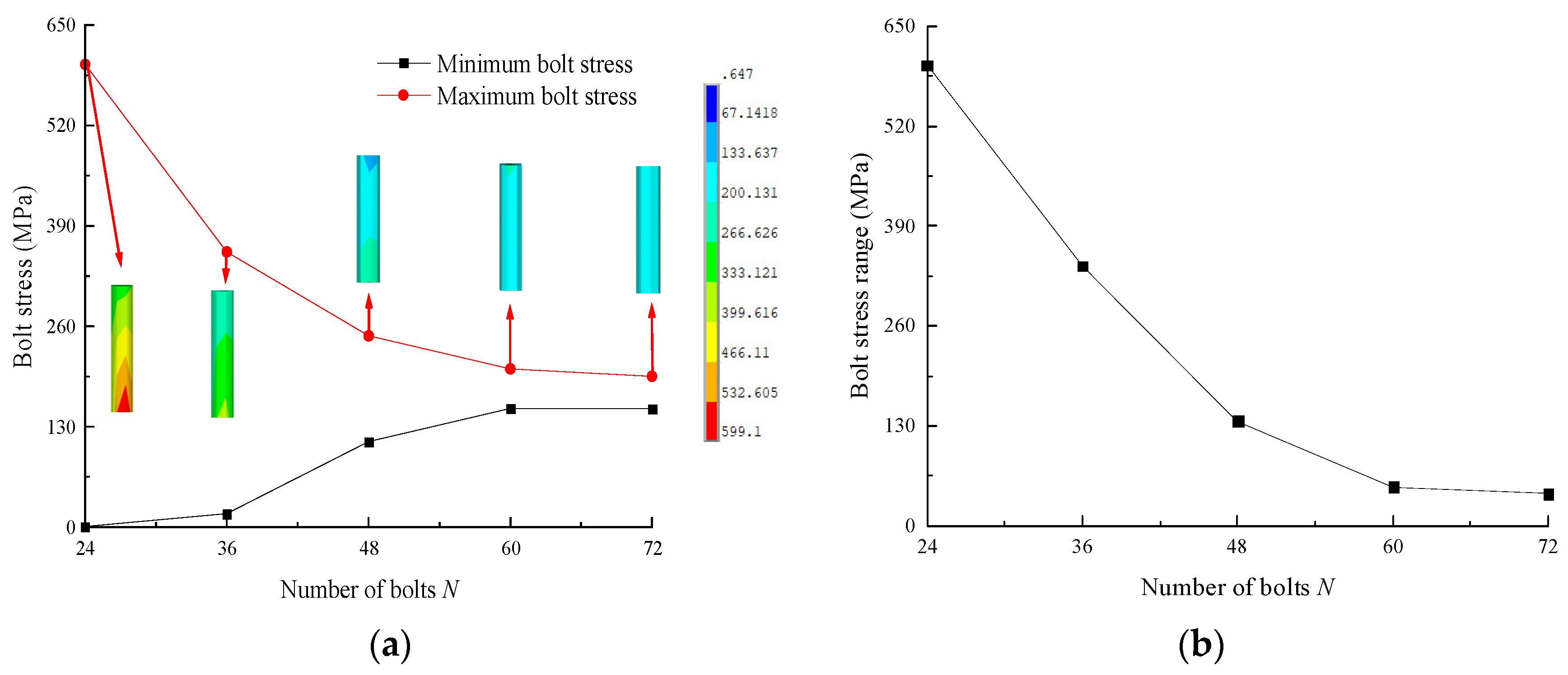
The maximum and minimum stress curves of the bolts and the stress range curve of bolts with different
N values are shown in
Figure 18. From the diagram, it can be seen that with the increase in
N, the maximum stress of the bolt and the range of bolt stress decrease gradually, while the minimum stress of the bolt increases gradually, and they are linearly related to
N. When
N increases from 24 to 72, the maximum stress of the bolt decreases gradually from 599.1 MPa to 195.28 MPa, a decrease of 67.40%; the minimum stress increases gradually from 0.65 MPa to 153.48 MPa; and the bolt stress range decreases gradually from 598.46 MPa to 41.8 MPa, a decrease of 93.02%. These findings indicate that increasing
N is beneficial for improving the uniformity of the bolt stress distribution.
The reason why the bearing deformation, inner and outer ring deformation, rolling element deformation, rolling element contact load, maximum stress and minimum stress of bolts, and bolt stress range change with N is because, under the same external load conditions, as N increases, the external load is borne by more bolts, so the load on the rolling element and the single bolt decreases, and finally the deformation decreases. However, with the increase in N, the circumferential wall thickness of the inner and outer rings of the bearing are reduced, which leads to the decrease in the bearing capacity of the inner and outer rings of the bearing. Therefore, under the condition of meeting the structural size, selecting a higher N value is beneficial for improving the bearing capacity of slewing bearings and bolts.
3.4. Influence of Pre-Tightening Force Coefficient P
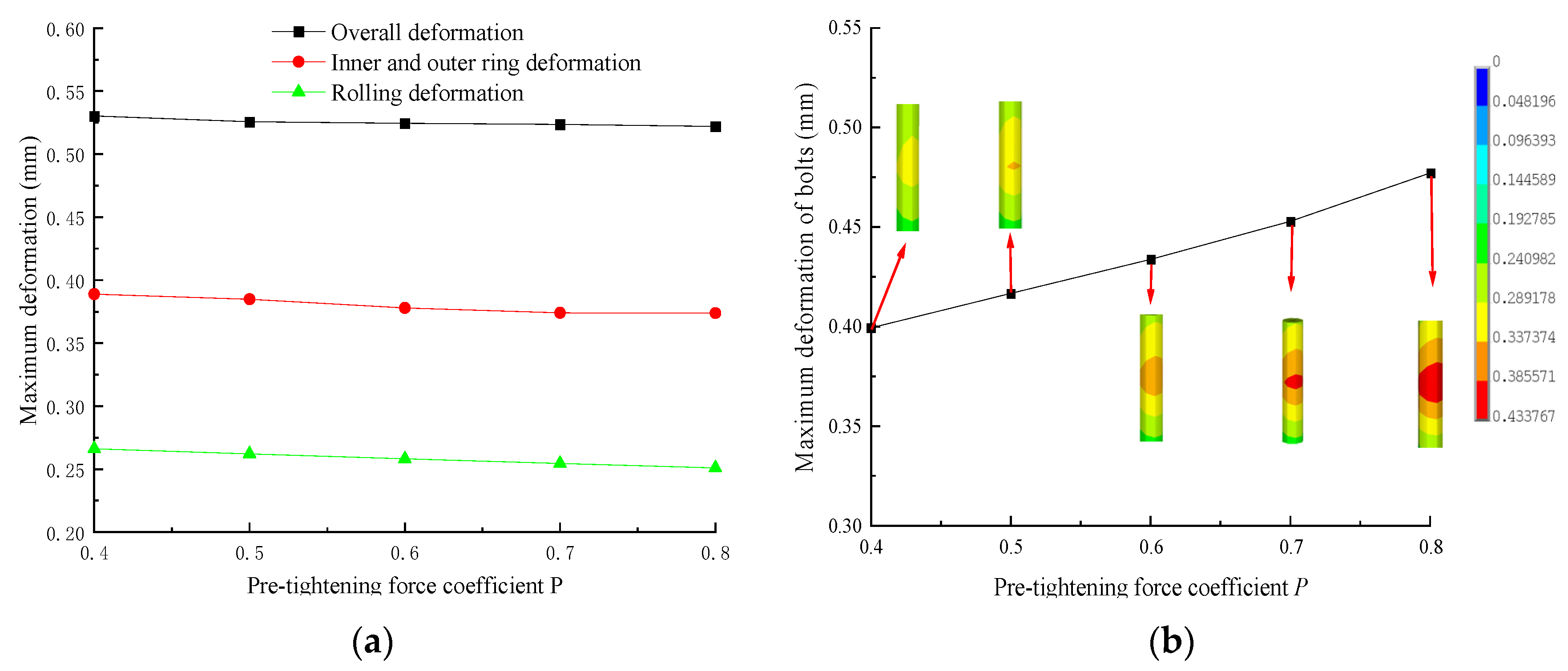
The maximum deformation curves of slewing bearings, inner and outer rings, rolling elements, and bolts with different pre-tightening force coefficients (
P) are shown in
Figure 19. From the diagram, it can be seen that as
P increases, the maximum deformation of the slewing bearing, inner and outer rings, rolling elements, and bolts gradually decreases. When
P increases from 0.4 to 0.8, the maximum deformation of the upper support decreases from 0.530 mm to 0.522 mm, the maximum deformation of the inner ring decreases from 0.385 mm to 0.374 mm, the maximum deformation of the rolling elements decreases from 0.266 mm to 0.251 mm, and the maximum deformation of the bolts decreases from 0.399 mm to 0.477 mm, representing decreases of 1.51%, 2.86%, 5.86%, and 19.55%, respectively.
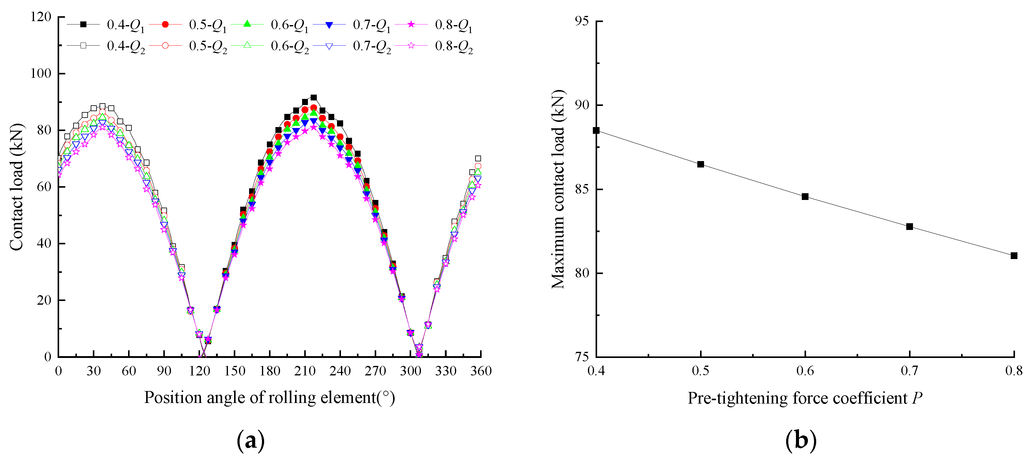
The contact load distribution curves of the rolling element and the maximum contact load curve of the rolling element with different
P values are shown in
Figure 20. From the diagram, it can be seen that the load distribution at different
P values is a cosine curve, and the contact load reaches the maximum when the position angle of the rolling element is 37.5°. With the increase in
P, the maximum contact load of the rolling element decreases, but the contact load distribution curve is close, indicating that the change has little effect on the contact load of the rolling element. When
P increases from 0.4 to 0.8, the maximum contact load of the rolling element gradually decreases from 88.5 kN to 81 kN, a decrease of 8.42%.
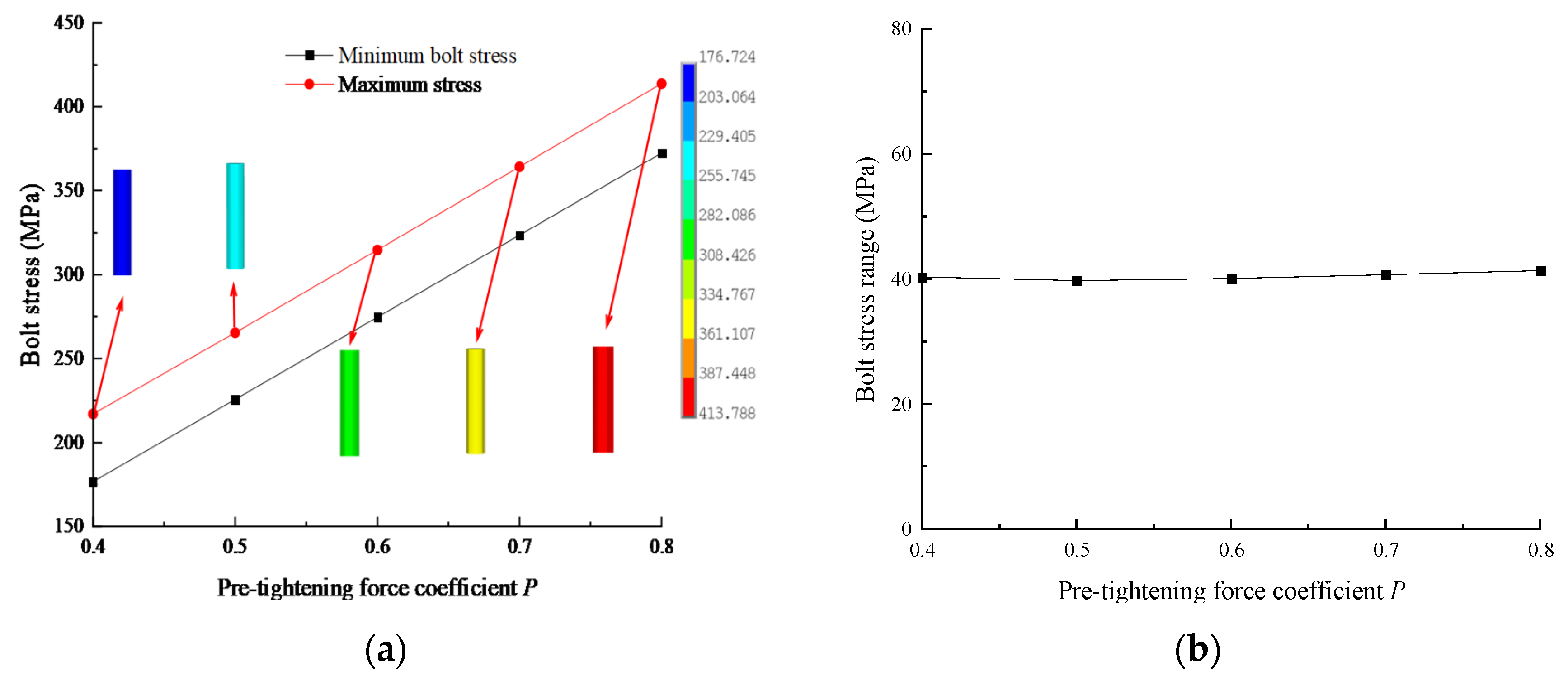
The maximum and minimum stress curves of the bolts and the stress range curve of bolts with different
P values are shown in
Figure 21. From the diagram, it can be seen that with the increase in P, the maximum stress of the bolt and the range of bolt stress decrease gradually, while the minimum stress of the bolt increases gradually, and they are linearly related to
P. When
P increases from 0.4 to 0.8, the maximum stress of the bolt increases gradually from 217.03 MPa to 413.79 MPa, an increase of 90.66%; the minimum stress increases gradually from 176.72 MPa to 372.48 MPa; and the bolt stress range decreases gradually from 40.31 MPa to 41.31 MPa, a decrease of 2.48%. These findings indicate that increasing
P has little effect on the uniformity of the bolt stress distribution.
The reason why the bearing deformation, inner and outer ring deformation, rolling element deformation, rolling element contact load, maximum stress and minimum stress of bolts, and bolt stress range change with P is because, under the same external load conditions, as P increases, the deformation and stress of the bolt increase, and the connections between the inner and outer rings and the support become closer and closer, resulting in a decrease in the deformation and stress of the inner and outer rings and the rolling element. Therefore, increasing P will reduce the deformation of the slewing bearing, and the load and deformation of the rolling element will also decrease. Thus, under the condition of satisfying the yield strength of the bolt, selecting the appropriate P value is beneficial for improving the bearing capacity of the slewing bearing and the bolt.
3.5. Influence of Radial Load-Overturning Moment Angle θ
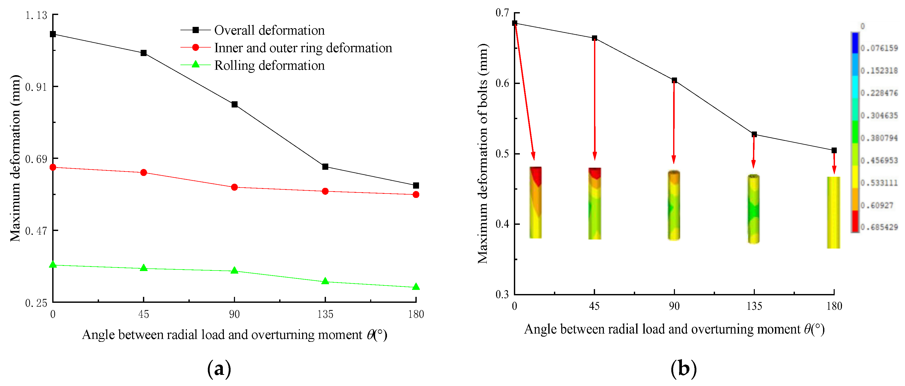
The maximum deformation curves of slewing bearings, inner and outer rings, rolling elements, and bolts with different radial loads and overturning moment angles (
θ) are shown in
Figure 22. From the diagram, it can be seen that as
θ increases, the maximum deformation of the slewing bearing, inner and outer rings, rolling elements, and bolts gradually decreases. When
θ increases from 0° to 180°, the maximum deformation of the upper support decreases from 1.070 mm to 0.580 mm, the maximum deformation of the inner ring decreases from 0.663 mm to 0.575 mm, the maximum deformation of the rolling elements decreases from 0.364 mm to 0.296 mm, and the maximum deformation of the bolts decreases from 0.685 mm to 0.505 mm, representing decreases of 45.79%, 13.27%, 18.27%, and 18.5%, respectively.
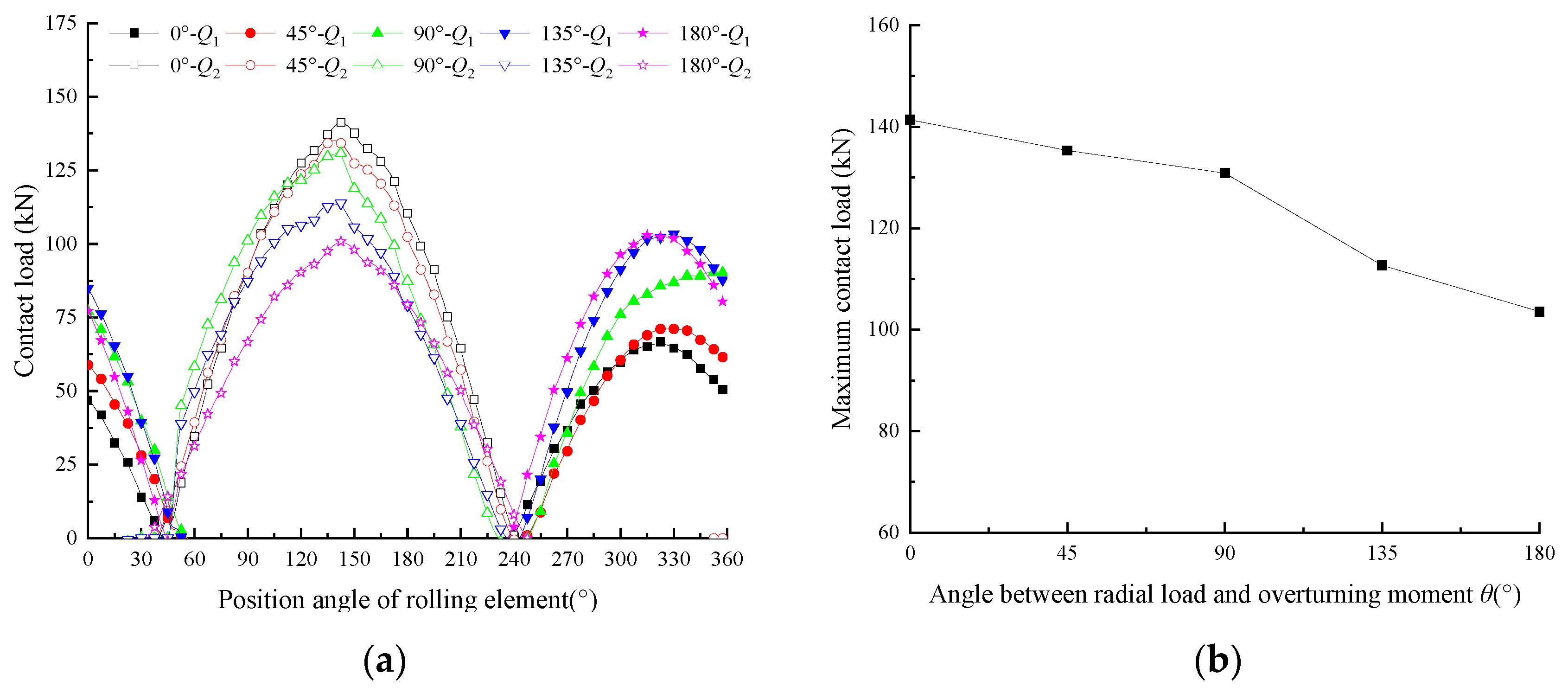
The contact load distribution curves of the rolling element and the maximum contact load curve of the rolling element with different
θ values are shown in
Figure 23. From the diagram, it can be seen that the load distribution at different
θ values is a cosine curve, and the contact load reaches the maximum when the position angle of the rolling element is 142.5°. The maximum contact load of the rolling element decreases gradually with the increase in
θ. When
θ increases from 0° to 180°, the maximum contact load of the rolling element gradually decreases from 141.4 kN to 103.6 kN, a decrease of 26.74%.
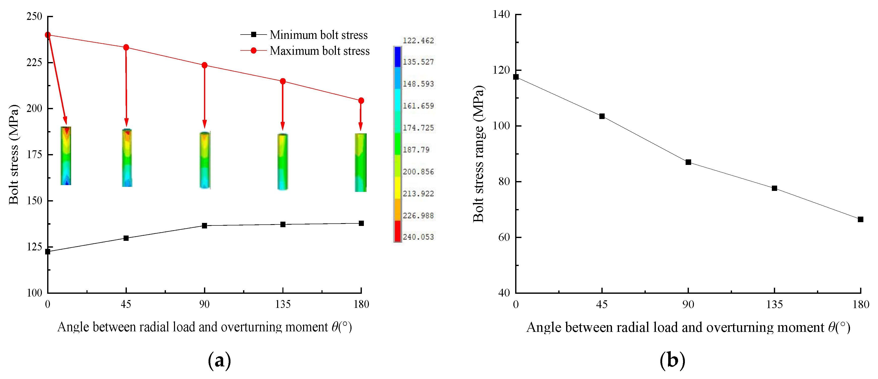
The maximum and minimum stress curves of the bolts and the stress range curve of bolts with different
θ values are shown in
Figure 24. From the diagram, it can be seen that with the increase in
θ, the maximum stress of the bolt and the range of bolt stress decrease gradually, while the minimum stress of the bolt increases gradually, and they are linearly related to
θ. When
θ increases from 0° to 180°, the maximum stress of the bolt decreases gradually from 240.05 MPa to 204.37 MPa, a decrease of 14.86%; the minimum stress increases gradually from 122.46 MPa to 137.85 MPa; and the bolt stress range decreases gradually from 117.59 MPa to 66.52 MPa, a decrease of 43.43%. These findings indicate that increasing
θ can improve the uniformity of the bolt stress distribution.
The reason why the bearing deformation, inner and outer ring deformation, rolling element deformation, rolling element contact load, maximum stress and minimum stress of bolts, and bolt stress range change with θ is because, under the same external load conditions, when the radial load acts on the upper-end face of the upper support, an overturning moment is generated at the same time. When θ is 0°, this moment is superimposed with the overturning moment. With the increase in the angle, this moment is offset with the overturning moment, and the offset degree reaches the maximum when the angle reaches 180°. Therefore, with the increase in θ, the load on the rolling element and the bolt gradually decrease, and finally, the deformation of the rolling element and the deformation and stress of the bolt also decrease. Thus, situations where the value of θ is quite small should be avoided, which is beneficial for improving the bearing capacity of slewing bearings and bolts.
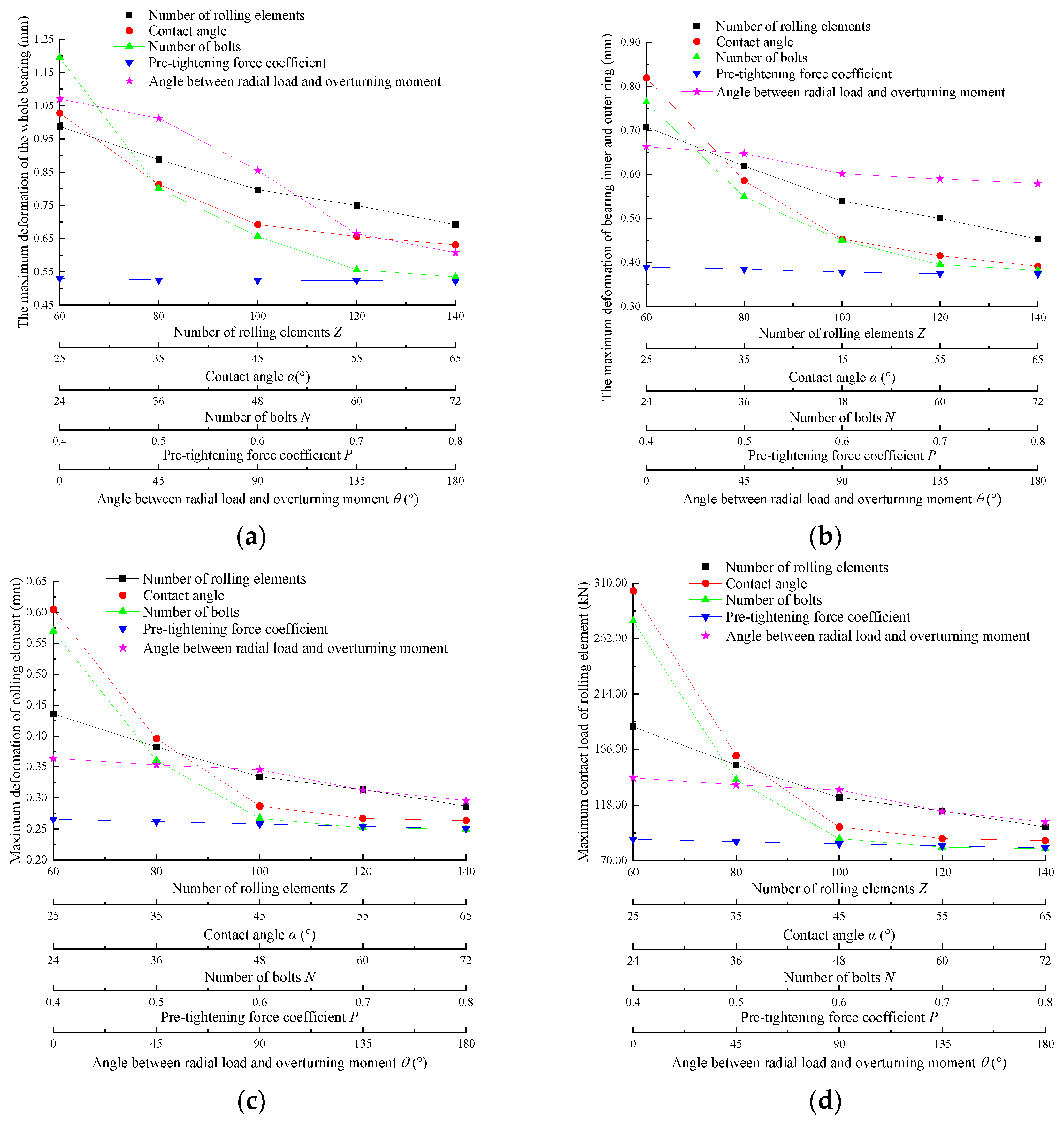
3.6. Analysis of the Influence Degree of Each Factor
The influence degrees of different influencing factors, determined through the above analysis, is shown in
Figure 25. With increases in
Z,
α,
N,
P, and
θ, as can be seen from
Figure 25a, the maximum deformation of the bearing decreases by 29.96%, 38.62%, 55.23%, 1.51%, and 45.79% respectively; the degree of influence, ranked from large to small, is
N,
θ,
α,
Z, and
P. It can be seen from
Figure 25b that the maximum deformation of the inner and outer rings decreases by 36.02%, 52.26%, 50%, 2.86%, and 13.27%, respectively; the degree of influence, ranked from large to small, is
α,
N,
Z,
θ, and
P. It can be seen from
Figure 25c that the maximum deformation of the rolling body decreases by 34.17%, 56.36%, 56.32%, 5.63%, and 18.68%, respectively; the degree of influence, ranked from large to small, is
α,
N,
Z,
θ, and
P. It can be seen from
Figure 25d that the maximum contact load of the rolling element decreases by 46.63%, 71.20%, 71.03%, 8.42%, and 26.74%, respectively; the degree of influence, ranked from large to small, is
α,
N,
Z,
θ, and
P. It can be seen from
Figure 25e that the maximum deformation of the bolt decreases by 32.95%, 49.08%, 56.62%, 19.55%, and 23.07%, respectively; the degree of influence, ranked from large to small, is
N,
α,
Z,
θ, and
P. It can be seen from
Figure 25f that the maximum stress of the bolt decreases by 20.26%, 19.76%, 67.40%, 90.66%, and 14.86%, respectively; the degree of influence, ranked from large to small, is
P,
N,
Z,
α,
θ. It can be seen from
Figure 25g that the bolt stress range decreases by 46.02%, 48.92%, 93.02%, 2.48%, and 43.43%, respectively; the degree of influence, ranked from large to small, is
N,
α,
Z,
θ,
P. From the above, it can be seen that increasing
α,
N,
Z, and
θ can reduce the deformation, and increasing
α,
N,
Z, and
θ can reduce the contact load. Increasing
P,
N,
Z, and
α can reduce the maximum stress of bolts. Increasing
N,
α,
Z, and
θ can increase the uniformity of bolt stress distribution. Considered comprehensively, the comprehensive performance of bearings and bolts can be improved by increasing
α,
N,
Z, and
θ.


 ,
, 


