1. Introduction
As the global economy continues to grow rapidly and the exploration of marine resources deepens, vessel-mounted cranes play a critical role in executing maritime operations, such as cargo transfer, shipwreck salvage, and the construction and maintenance of offshore platforms. For instance, offshore wind power, one of the fastest-growing renewable energy sources [
1], relies heavily on vessel-mounted cranes for installation [
2]. However, during crane operations, vessel motion caused by waves and wind increases the amplitude of payload swing, making precise load positioning challenging [
3]. In such dynamic environments, vessel-mounted cranes must handle heavy loads with precise maneuvering, posing significant challenges to traditional crane operations. Therefore, developing an efficient motion compensation system is crucial for ensuring both the efficiency and safety of maritime operations, emphasizing the need for advanced crane systems to meet the demands of marine engineering.
Existing research on vessel-mounted crane motion compensation systems includes the design of specialized crane controllers and the optimization of trajectory algorithms. For example, Qian et al. [
4] developed an enhanced adaptive neural network antisway tracking control strategy for ship-to-ship crane systems operating in complex marine environments. The system can adapt to unknown wave disturbances while maintaining stable tracking performance. Similarly, Lu et al. [
5] proposed an online trajectory planning method for three-dimensional marine cranes to manage continuous rolling and heaving motion disturbances of vessels. This method initially designs preliminary trajectories for different crane actions and makes real-time adjustments to mitigate or eliminate cargo sway caused by operational errors and vessel movement. The design objective of these motion compensation systems is to minimize the impact of marine environmental factors, such as waves and wind, on crane operations. By adjusting the crane’s operational parameters and paths in real time, these systems can effectively stabilize crane sway caused by environmental conditions. However, the effectiveness of these compensation systems heavily relies on the accurate detection and tracking of crane motion states. Traditional land-based detection technologies often fall short in complex marine environments. For instance, the optical three-dimensional tracking system requires a fixed reference point during testing, rendering it unsuitable for measuring the motion of floating structures [
6]. This limitation underscores the importance of developing a position and attitude detection system specifically tailored for maritime environments.
Significant progress has been made in developing detection systems tailored for marine environments to accurately detect the position and attitude of maritime targets. Currently, the motion tracking of floating structures primarily relies on measurements from gyroscopes, accelerometers, and GPS. For example, Prislin et al. [
7] installed the world’s first Spar platform in the Gulf of Mexico and tested its six-degree-of-freedom (DOF) motion response using two GPS devices and an inclinometer. Recently, Liu et al. [
8] proposed a novel nonintegral displacement reconstruction method for targets, such as offshore platforms and wind turbines, converting easily measurable accelerations into target displacements using complex exponential series. Liu et al. [
9] also developed a motion-tracking method based on accelerometer and angular velocity data, employing quaternion techniques to correct tilt and coordinate errors of accelerometers, thereby establishing an innovative displacement reconstruction model for accurately estimating the translational displacement of floating structures. Similarly, Han et al. [
10] captured vertical acceleration signals of ships using accelerometers and processed them with a time-frequency domain integration algorithm, effectively avoiding problems associated with second-order trend items and low-frequency signal interference, thereby accurately obtaining the heave displacement of ships. Zhao et al. [
11] used four sets of accelerometers to correct integration effects in the vertical direction, combining data from angle sensors and accelerometer groups using Kalman filter technology to determine the optimal tilt angle. These studies demonstrate that advanced sensor technology and sophisticated data processing methods can effectively monitor and estimate the position and attitude of maritime vessels, providing key technical support for maritime operations. However, these technologies may encounter issues such as data errors or complete data loss, including data jumps, drifts, and instabilities, which can lead to structural misalignment or inadvertently drive the structure to a nontarget position, potentially causing accidents [
12]. To address the challenges of using IMU-based systems to measure the location of targets in marine environments, previous research has explored sensor fusion methods to enhance target measurements.
For example, a berthing information extraction system based on 3D lidar data was experimentally validated on a ro-ro ship, demonstrating its effectiveness in dynamic target recognition and safe docking [
13]. Another framework for maritime autonomous surface ships utilized shipborne lidar to estimate key berthing parameters, such as speed, angle, and distance, achieving the required accuracy in real time [
14]. In addition, the development of a low-cost lidar-based docking system, which fuses lidar data with GNSS positioning data, has been shown to be effective during various berthing maneuvers when compared to traditional GNSS-based navigation aids [
15]. Bollard segmentation and position estimation from lidar point cloud data have also been proposed to facilitate autonomous mooring [
16]. Similarly, data from two motion reference units and a laser tracker could be combined using sensor fusion techniques, and the relative positions and attitudes of the two vessels were estimated using an extended Kalman filter. Despite these advancements, lidar technology faces certain limitations in autonomous vessel applications, such as restricted laser power due to eye safety, limited operational range, high optical costs, and unsuitability for harsh environments. Although the maritime environment presents fewer objects and noise compared to land [
17], lidar measurements remain challenging. For instance, light penetration into water results in no feedback signal, making sea detection different from road detection. Additionally, reflections from algae and seagrass on the water surface can cause false positives, and sea turbulence, such as that caused by a ship’s propeller, further complicates detection [
18].
Meanwhile, as visual sensors have become ubiquitous, vision-based detection systems have been widely adopted in various applications, including automated control, aerial navigation, and autonomous driving [
19]. For instance, Qin et al. [
20] employed a tightly coupled, nonlinear optimization-based approach that integrates inertial measurement unit (IMU) preintegration measurements with feature observations to achieve high-precision visual-inertial odometry. Similarly, Meng et al. [
21] developed a vision and inertial integrated guidance method for drone shipboard landing, using an onboard visual system and an IMU, fused with an extended Kalman filter, to estimate the drone’s position, attitude, and speed relative to the runway. Wu et al. [
22] proposed a binocular vision system aided by coded cylinders to measure the translational and rotational coupled vibrations of cables induced by external excitations, such as wind and rain. Photogrammetry was used to obtain the three-dimensional coordinates of coded points, and cylinder fitting was employed to derive the 6DOF generalized displacement of the cable. Geir Ole Tysse et al. [
23] introduced a vision-based controller for managing the motion of articulated crane tips and compensating for vibration by monitoring and tracking spherical markers installed on the payload cable using three cameras mounted on the crane. Additionally, Carlos Campos [
24] introduced a method combining tightly integrated visual-inertial simultaneous localization and mapping (SLAM) with a new place recognition technique, achieving real-time, high-precision mapping of environments, and maintaining operational robustness by creating new maps and seamlessly merging them with old ones under poor environmental understanding. Fangli Mou et al. [
25] proposed a precise and efficient method for estimating the attitude of handling connectors based on visual pose estimation and admittance control.
Many of the research works mentioned above are based on vision systems. However, since most of these systems use traditional computer vision techniques, accuracy issues may arise. Therefore, object detection technology is considered an excellent alternative for position estimation, effectively improving accuracy. In recent decades, significant progress has been made in object detection technology, particularly learning-based methods, such as the research results presented in [
26,
27], which have become groundbreaking contributions in this field. Several studies have also integrated learning-based methods into vision-based robotic systems. For example, in [
28], YOLOv4 was used to develop an autonomous drone system for electrical and mechanical equipment. Furthermore, deep learning-based trackers have been applied to surveillance tasks in drone systems [
29]. While visual sensors are effective at capturing environmental imagery, they are sensitive to real-time changes and environmental factors. On the other hand, inertial sensors (such as accelerometers and gyroscopes) offer precise attitude and motion information and are unaffected by lighting or occlusions. By integrating data from both types of sensors, the system can maintain accuracy and stability in complex environments. To further enhance system robustness, multisensor fusion technology is introduced, combining data from various sensors (such as visual and inertial sensors) to compensate for the limitations of individual sensors. Common data fusion algorithms include least squares and Kalman filters. Compared to least squares, the Kalman filter is capable of handling noisy dynamic systems, updating state estimates in real-time, and offering higher computational efficiency. Additionally, it does not require storing historical data, making it well-suited for fusing data from multiple sensors while effectively addressing uncertainty and noise, ensuring the accuracy of estimations.
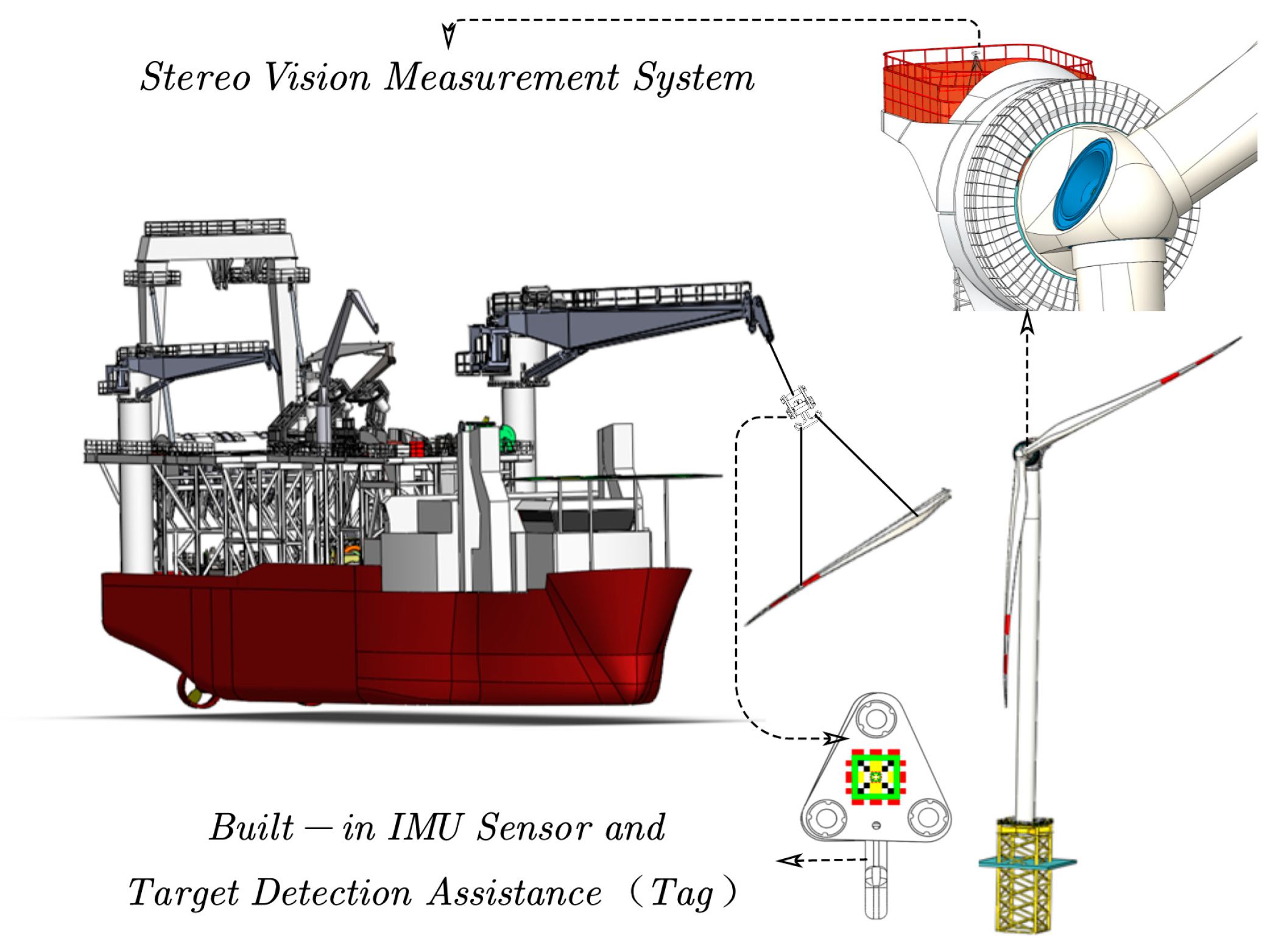
Inspired by the burgeoning development of computer vision techniques, it has been observed that computer vision-based measurement solutions are still lacking in the field of position and attitude detection in marine environments. Additionally, an analysis of existing maritime motion detection systems reveals that they primarily focus on the three degrees of freedom (DOF): roll, pitch, and heave. However, ships at sea can also experience significant movements in horizontal directions due to waves traveling at certain velocities, affecting the x and y axes. To address this issue comprehensively, we designed a motion detection system that incorporates 5DOF, including the capability to detect displacements in the x and y directions. To overcome these challenges, this paper proposes a specialized multisensor monitoring system that combines vision and inertial sensing technologies to measure the motion state of targets within vessel-mounted cranes. As shown in
Figure 1, the system utilizes a stereo camera to capture the relative position relationship between the hook and the camera coordinate system and employs two IMUs to obtain relative acceleration and attitude information. A linear Kalman filter is then applied to integrate data from the camera and the IMUs, enhancing the accuracy of the target data. During operation, specially designed tags are attached to the hook to be monitored, and the detection camera is positioned on the target platform. The two IMUs are fixed on the camera and the detection tag, respectively, to measure the relative position and attitude changes between the target and the platform where the camera is located.
The innovations of this study include: (1) Proposing a method for the vessel-mounted crane’s working environment where camera and computing devices are fixed at the target lifting location, thereby being positioned separately from the detection target; (2) enabling the real-time acquisition of relative position and attitude information between the lifting cargo and the target location; (3) obtaining multidegree-of-freedom information of maritime targets, including displacements in the x, y, and z directions as well as roll and pitch angles. The remainder of this paper is structured as follows:
Section 2 elaborates on the specific implementation process of the proposed method,
Section 3 discusses the experimental design and evaluation of results, and
Section 4 concludes the paper.
2. Materials and Methods
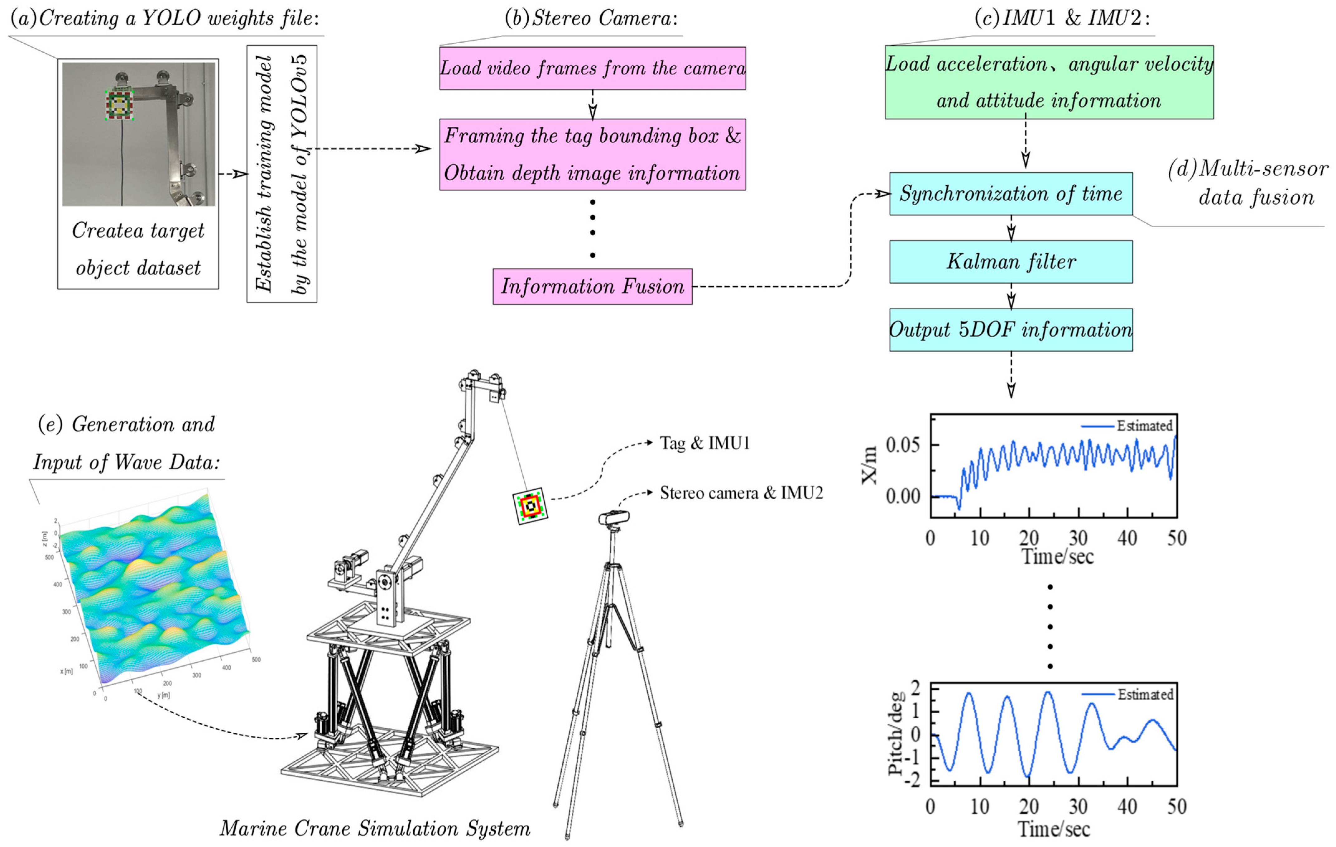
In this section, this paper introduces a system that integrates data from a stereo camera and two IMUs for precise target tracking and attitude estimation of cargo on vessel-mounted cranes. As illustrated in
Figure 2, the system begins by creating a YOLO [
27] training dataset and using it to train the model. Subsequently, continuous video frames are captured by the camera, and image processing techniques are utilized to determine the target’s position. To ensure stable tracking, the simple online and real-time tracking (SORT) algorithm [
30] is adopted, while depth information is obtained from the stereo camera to calculate the target’s three-dimensional coordinates. Simultaneously, the IMU module provides angular velocity, attitude, and acceleration data. To ensure data accuracy, the system matches the timestamps of the camera and IMU data, using interpolation methods to synchronize the data acquisition from both sensors at the same temporal point. Finally, the synchronized data is processed through a Kalman filter to fuse the target’s most probable state, thereby achieving precise tracking and attitude estimation of dynamic targets. This system effectively combines the advantages of visual and inertial sensors, enhancing tracking and localization accuracy in marine environments.
2.1. Target Identification
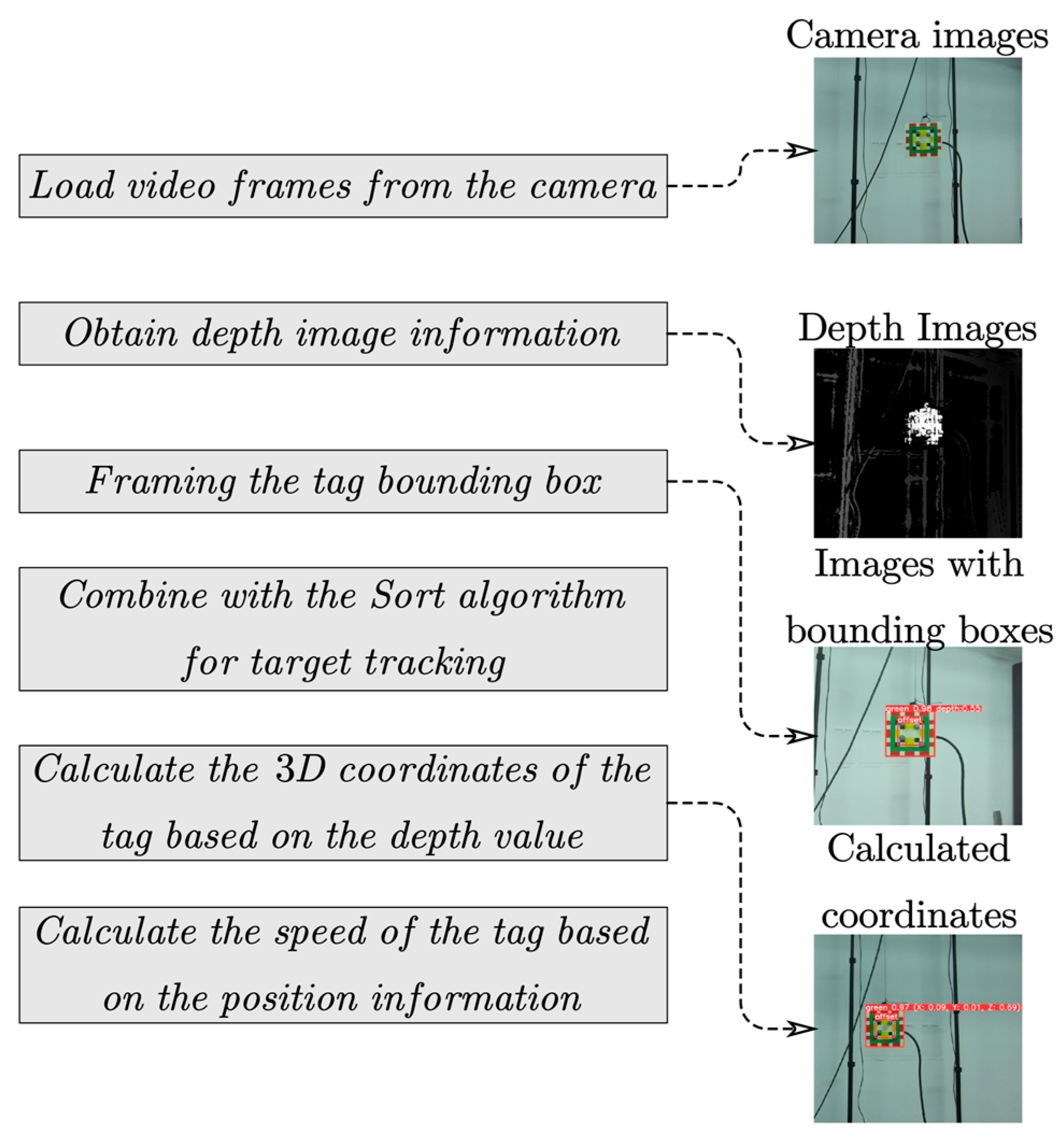
In this study, this paper applies the YOLOv5 algorithm to target detection for vessel-mounted cranes in marine environments, addressing the challenge of efficient target recognition in complex maritime settings. The main flow is shown in
Figure 3. To facilitate the deployment of the YOLOv5 model, a tag is installed on the detection cargo as the target for detection. Based on this setup, we created a dataset of 4000 images, consisting of 3200 training images and 800 validation images. These labeled images were captured from different angles and under different lighting conditions, with manual labeling performed using LabelImg 1.8.6, as shown in
Table 1. After training, the model achieved an average recall rate of 0.997 and a detection rate of 0.998, demonstrating its effectiveness and accuracy in complex environments. All model training and testing were conducted on a high-performance PC equipped with two AMD EPYC 7763 CPUs, an Nvidia RTX A6000 GPU, and 512 GB of RAM.
During the transfer of cargo between offshore fixed platforms and cargo ships, the distance between detection tags and the camera fluctuates significantly. At longer distances, tags may not be detected, while at shorter distances, incomplete detection may occur. To address these issues, we implemented a simple yet highly distinguishable tag and carefully constructed a training dataset for model development. The validation results show that the model does not exhibit overfitting. The recursive tag system, with its embedded design, adapts to various detection distances. Each tag contains a central “ignore” region in which a smaller tag is embedded. This design ensures that a tag of suitable size is always effectively recognized, regardless of the distance. Based on the AprilTag3 system [
31], we developed a series of tags composed of 10 × 10 cell arrays, with a 2 × 2 cell area in the center devoid of data. To ensure effective multiscale detection, we printed two sizes of tags at a 5:1 ratio, where the smaller tags are embedded within the larger ones, achieving consistent detection accuracy across varying distances. This design not only balances detection accuracy at both near and far ranges through size scaling, but also significantly reduces the likelihood of incomplete tag recognition caused by dynamic distance changes. The larger tags ensure visibility at longer distances, while the smaller embedded tags ensure clear recognition at close range. This multiscale detection approach effectively enhances the adaptability of the tags to different maritime environments, reduces detection errors, and improves the overall reliability and robustness of the system under fluctuating operational conditions.
In the context of this study, we focus primarily on the critical stages of cargo handling or equipment installation, particularly the final stages of hoisting operations. In these scenarios, the movement of the load is relatively controlled, and the target location is well-defined. Therefore, camera placement only needs to be directed at the target area, ensuring accurate monitoring of the load during the final installation or placement stage. This solution guarantees that the load remains within the camera’s field of view during key operational phases, without requiring continuous monitoring throughout the entire hoisting process.
The proposed approach not only demonstrates the potential application of YOLOv5 in target recognition for vessel-mounted cranes but also effectively addresses recognition issues at varying distances through the innovative design of recursive labels, significantly enhancing the efficiency and safety of detection tasks.
2.2. Estimation of Label Position
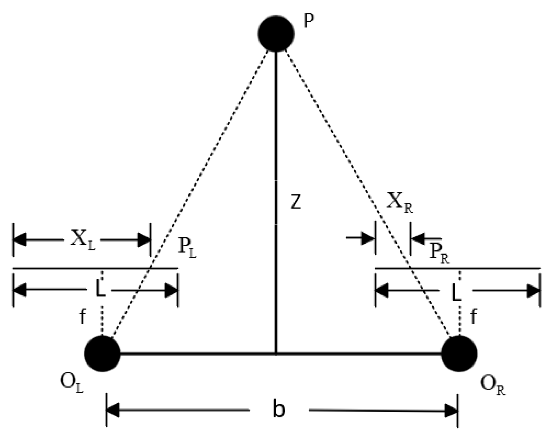
Obtaining the three-dimensional coordinates of a measured object involves depth calculation, 3D coordinate solving, and target tracking. After framing the target within the camera’s view using YOLO, determining its position in the world coordinate system first requires calculating the target’s depth within the camera coordinate system. The depth image obtained from the stereo camera provides the depth information of each pixel point relative to the camera, which is essential for solving the object’s three-dimensional coordinates. By applying the parallel binocular vision model, the depth of image pixels can be accurately calculated.
The origins of the camera coordinate systems, denoted as
and
, represent the optical centers of the left and right cameras, respectively, as shown in
Figure 4. The distance between the projection centers of the two cameras, referred to as
, is also known as the baseline. Any point
in three-dimensional space is imaged at
on the left camera and
on the right camera. Based on the principle of linear propagation of light, the three-dimensional point
is located at the intersection of the lines connecting the projection centers of the cameras with their respective image points. The segments
and
represent the distances from the left and right image points to the left imaging plane, respectively. Thus, the disparity of points
as seen from the left and right cameras can be defined as follows:
The distance between the two imaging points
and
is:
Then, the distance
from the point
to the plane of the center of projection can be obtained:
When the point
moves in three-dimensional space, its imaging position on the left and right cameras will change, causing the parallax to adjust accordingly. From the aforementioned formula, the parallax is inversely proportional to the distance between the point and three-dimensional space to the projection center plane. Therefore, if we know the parallax of a point, we can determine the depth information of the point.
where
denotes the camera focal length, while X and Y represent the coordinates of an object in the camera coordinate system, with
and
being the coordinates of the object on the camera image plane. During the measurement process, the depth image from the stereo camera is first aligned with the image from the left lens. The YOLO algorithm is employed to detect the destination tag in the output image from the left camera. When determining the center depth of the bounding box obtained by the YOLO algorithm, the most representative depth value is selected as the optimal depth for tracking object motion.
However, the depth values returned from the stereo camera may contain zeros or infinity, which cannot be directly used. A method for determining the optimal depth value is applied when processing the depth data. If the center data of the bounding box is valid, the current depth value is saved and used to calculate the target’s three-dimensional coordinates [
32]. If the center value of the bounding box is zero or infinite, the eight neighboring points are sequentially searched, and the center depth value is replaced by the valid depth value from the nearest neighborhood. If all eight neighboring areas are invalid, the process exits the current loop, scales down the entire region within the bounding box to eliminate bad values, sums the remaining depth values, and calculates the average. This average depth value is then used as the depth for the current bounding box, from which the target’s three-dimensional coordinates are derived.
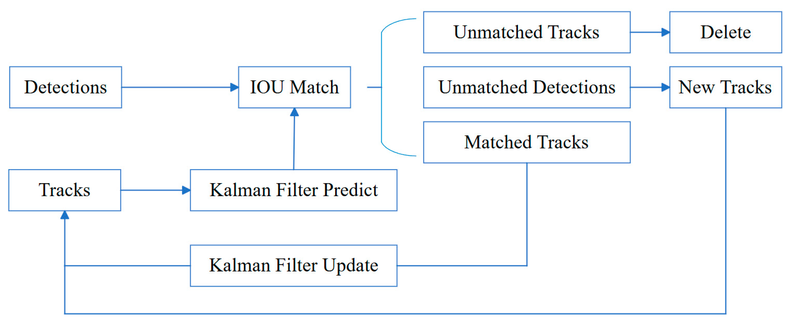
During continuous detection tasks, the goal of object detection is to predict the position and category of target objects, often neglecting the spatiotemporal correlation between successive frames. However, in practical applications, various factors can cause the loss of target frames. To improve the positional correlation of target objects across different frames, the SORT algorithm is commonly used. As illustrated in
Figure 5, this algorithm utilizes Kalman filtering and Hungarian matching techniques, with the intersection over union (IOU) between tracking results and detection outcomes serving as the cost matrix, enabling continuous tracking of targets. Below is the state model representation of the SORT algorithm:
In the described context, and represent the horizontal and vertical coordinates of the target center, respectively, while and denote the size and ratio of the target frame. The Kalman filter updates the state prediction after successfully associating the detection results with the tracking trajectories. The core principle of SORT involves identifying target information in each image using the Hungarian algorithm. Detection results are then updated through data association with the Kalman filter and linked via IOU matching. For detections with low overlap, new trackers are created, and if a target is not detected over several frames, its tracker is terminated. This approach maintains object identity, minimizes long-term prediction errors, and ensures tracking efficiency by promptly deleting lost targets and resuming tracking when targets reappear.
In
Figure 5, “Detections” refers to the results produced by the detection algorithm, while “Tracks” represents the tracking set generated by the Kalman filter’s predictions, which are then updated through data association. IOU matching is conducted between “Detections” and “Tracks”. “Unmatched Tracks” indicates instances where the matching process has failed, whereas “Matched Tracks” denotes successful matching between “Tracks” and “Detections”.
2.3. Acquisition of Target Attitude Using IMUs
This section discusses the technical application of a six-axis IMU to acquire the pitch and roll angles of cranes. The six-axis IMU consists of a gyroscope and an accelerometer, which together provide measurement data across three axes. This data is essential for accurately capturing the target’s attitude in the pitch and roll directions.
Initially, the gyroscope measures angular velocity continuously along each axis, providing real-time data necessary for calculating changes in the target’s angle. Specifically, the new angle values are determined by adding the product of the integrated angular velocity over a period to the angle measured at the previous moment. The formula is as follows:
In this context, represents the angular value at the current moment, is the angular value at the previous moment, denotes the angular velocity measured by the gyroscope at the current moment, and represents the integration time, which also denotes the sampling period of the gyroscope. A smaller integration time leads to a more accurate integrated output of the angle. However, cannot be infinitely small, and each integration interval inherently contains errors. These errors accumulate over time with each integration, ultimately causing the output angle to deviate from the actual angle, a phenomenon known as gyroscope drift. At this point, the accelerometer plays a crucial role. It can detect gravitational components, aiding in correcting the static tilt angle of the equipment relative to the ground. This capability is vital for compensating for the inherent inaccuracies in gyroscope data, ensuring more reliable and accurate angle measurements.
To enhance data accuracy and suppress errors, this study employs a complementary filtering algorithm. This algorithm leverages the high-frequency response capabilities of the gyroscope and the low-frequency stability characteristics of the accelerometer. By applying a high-pass filter to the gyroscope data and a low-pass filter to the accelerometer data, effective data fusion can be achieved. Moreover, by using high-performance microprocessors and advanced kinematic solving techniques, along with the Kalman filtering algorithm, the system rapidly and accurately computes the real-time motion attitude of the equipment.
In our shipborne crane detection system, the “stable state” refers to a condition relative to the world coordinate system. During lifting, the load’s attitude is measured against this state, which can be the crane’s initial motionless state or a predefined reference in the control system. The system tracks changes in the load’s attitude, providing data such as pitch and roll angles. This “stable state” may be a posture set by the operator or system or an absolute horizontal reference. In summary, the integration of a six-axis IMU with advanced data processing technologies provides real-time and precise measurements of pitch and roll angles for vessel-mounted cranes. The approach significantly enhances the stability of attitude measurement in complex maritime environments, providing data support for marine vision-inertial navigation detection systems.
2.4. Kalman Filter Designed
In this system, to improve the reliability of position and attitude estimation of the sling, a Kalman filter is designed to integrate data both from the camera and the IMU, enhancing the accuracy of target tracking. The state vector of the cargo can be written as:
In this research, , , and denote position coordinates, while , , and represent the velocities in the , , and directions of the camera coordinate system, respectively. Additionally, , and represent the accelerations in these three directions, respectively. and signify the roll and pitch angles in the camera coordinate system, respectively, while and represent the angular velocities in the roll and pitch directions, respectively. Specifically, the three-dimensional position coordinates are directly captured by the camera, and the velocity data is derived by calculating the change in position between consecutive image frames. The IMU provides measurements of acceleration, angle, and angular velocity, with acceleration being used to predict changes in position, and angles and angular velocities help maintain an accurate understanding of the object’s spatial attitude. Through the use of a Kalman filter, this visual and inertial data are fused and processed, enabling continuous and accurate estimation of the object’s state in dynamic environments. This data fusion technique not only enhances tracking accuracy but also increases the system’s robustness against sensor noise.
In the proposed system, the data measured can originate from either the visual system or the IMU. However, due to the differing update frequencies of the YOLO module and the IMU, the data are not synchronized. To address this issue, an interpolation method is employed to align the data from the camera with the high-frequency data from the IMU. Initially, the state estimation system collects acceleration and angular velocity data from the IMU, which are acquired at a higher frequency than the camera frames. To synchronize these two types of data, temporal interpolation of the IMU data is necessary to ensure that, at the exact moment each camera frame is captured, a corresponding accurate IMU reading is available.
The interpolation technique can be implemented using linear interpolation or more advanced methods, such as cubic spline interpolation. Considering the high demands for real-time processing during synchronization and given that the passive motion caused by marine disturbances is predominantly low frequency, linear interpolation is chosen. Linear interpolation is a simple yet effective technique that estimates intermediate values directly between two known points. Specifically, if we know the IMU data at times
and
, if a camera frame is captured at time
(which lies between these two points), the IMU data at time
can be obtained using the following linear interpolation formula:
Through this method, each camera frame is aligned with an IMU data point, allowing the data from the visual system and the IMU to be integrated into a unified framework for processing, as demonstrated in Algorithm 1. This is crucial for motion estimation tasks, as precise timing information is necessary to ensure the accuracy and robustness of the algorithms.
| Algorithm 1: Multi-sensor time synchronization and Kalman filter. |
| Input: |
| Camera data containing timestamps and corresponding position information on x, y, and z |
| IMU data containing timestamps and corresponding pitch and roll values |
| Output: |
| Updated state estimate |
| | for t_cam: where t_cam is the camera timestamp |
| | imu_before = find_closest_imu_before(t_cam) |
| | imu_after = find_closest_imu_after(t_cam) |
| | if imu_before and imu_after: |
| | pitch_interp = imu_before.pitch + (t_cam − imu_before.time) * where pitch_interp is the interpolated pitch angle |
| | (imu_after.pitch - imu_before.pitch)/(imu_after.time − imu_before.time) |
| | roll_interp = imu_before.roll + (t_cam − imu_before.time) * where roll_interp is the interpolated roll angle |
| | (imu_after.roll − imu_before.roll)/(imu_after.time − imu_before.time) |
| | else: |
| | pitch_interp = imu_before.pitch or imu_after.pitch |
| | roll_interp = imu_before.roll or imu_after.roll |
| | |
| | z_sync = combine(camera_position_at(t_cam), pitch_interp, roll_interp) where z_sync is the synchronized observation vector |
| | Containing both camera position and interpolated IMU data |
| | x_predict = F * x where F is the state transition matrix |
| |
x is the updated state estimate |
| | P_predict = F * P * F^T + Q where Q is the process noise covariance matrix |
| | z_predict = H * x_predict where H is the measurement matrix |
| | y = z_sync − z_predict where y is the measurement residual |
| | K = P_predict * H^T * (H * P_predict * H^T + R)^ − 1 where K is the Kalman gain |
| | x = x_predict + K * y |
3. Experimental Validation and Results
3.1. Design of the Experimental Setup
To verify the effectiveness of the proposed motion compensation system for offshore cranes, indoor simulation experiments are conducted on a self-constructed simulated offshore vessel-mounted crane system. This section describes the detailed system architecture and test environment.
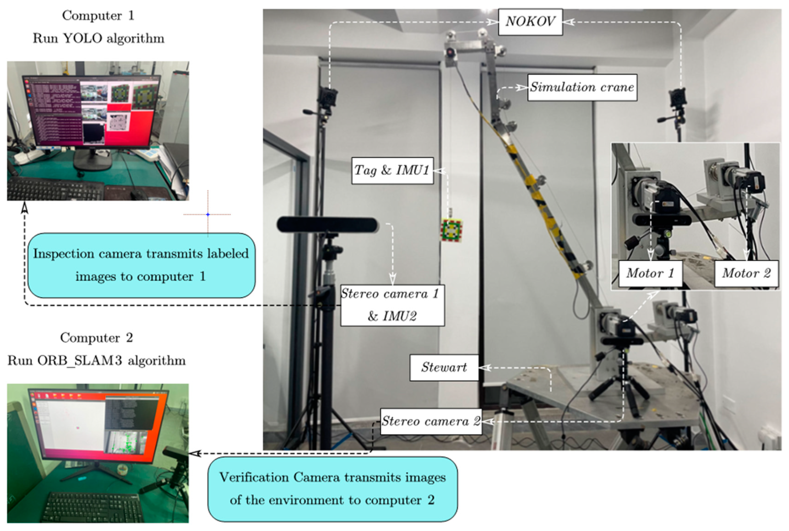
As illustrated in
Figure 6, our experiment was conducted in the following simulated scenario. We designed a miniature crane to simulate a vessel-mounted crane, with a crane arm measuring 1.5 m in length. The crane’s boom and hoist were driven by two Panasonic motors, specifically the MSMF082L1U2M and MSMF042L1U2M models. At the end of the hook, the cargo was attached and equipped with tags for identification and reflective spheres for detection by a motion capture system. We placed this simulated crane on a Stewart platform to mimic the movement of a vessel-mounted crane in a marine environment. By inputting scaled-down simulated ship movement data into the Stewart platform, we were able to replicate the dynamic motion of the crane at sea. Additionally, we mounted a ZED stereo camera and a ZED2 stereo camera from Stereolabs on tripods to simulate observing the dynamics of the load from a maritime platform. ZED camera 1 was connected to a computer equipped with an Intel Core i9-10900K CPU @ 3.70 GHz × 20 and an NVIDIA GeForce RTX 3080TI graphics card. ZED2 camera 2 was placed at the base of the simulated crane and connected to a computer equipped with an Intel Core i9-10900K CPU @ 3.70 GHz × 20 and an NVIDIA GeForce RTX 3090 graphics card. The experiment utilized two HWT9073-485 IMUs from WitMotion, with their specifications listed in
Table 2. In the experiment, the two IMUs were fixedly connected to Camera 1 and the tag, respectively. To assess the accuracy of measurements during the experiment, results measured by the NOKOV motion capture system composed of eight Mars2H were used as the ground truth. The experimentally generated data were benchmarked against the standards set by the International Maritime Organization (IMO) resolution MSC.363(92).
3.2. Validation of a YOLO-Based Localization Detection Systems
In this experiment, we aimed to evaluate and verify the accuracy of a YOLO-based visual localization algorithm and compare its performance with the ORB-SLAM3 algorithm. Conducted in a laboratory setting, the study measures the localization accuracy of the YOLO-based algorithm against traditional methods. Both YOLO and ORB-SLAM3 were deployed to measure the position of the same target, using positional accuracy data from the ORB-SLAM3 algorithm paper for comparison under identical conditions. To ensure alignment between the tags used for inspection and the binocular camera position where the SLAM algorithm was running, the tags were moved to the crane’s boom. To simulate a real marine environment, sinusoidal excitations of different frequencies were applied to the Stewart platform in three directions (x, y, and z axes), mimicking the dynamic movements encountered at sea. This setup aimed to test the stability and accuracy of the algorithms under dynamic conditions. The NOKOV motion capture system served as the benchmark system to obtain the actual positional data of the target, which was used to evaluate the positional estimates provided by the YOLO and ORB-SLAM3 algorithms. Through this set of experiments, we assessed the accuracy of the YOLO-based visual localization system and its performance relative to the established ORB-SLAM3 system in practical applications.
The results of the comparative experiments are shown in
Figure 7, where ‘YOLO’ represents the results from the YOLO-based visual detection system, ‘ORB-SLAM3’ represents the measurements obtained using that algorithm, and ‘NOKOV’ represents the results measured by the motion capture system. The results of the experiments show that, compared to SLAM-type algorithms, this measurement based on known tags as targets applied in this paper obtains higher accuracy during the experiments. In contrast, the YOLO (purple line) results stay very close to the ground truth (green dashed line), which indicates that the proposed learning-based system has a more stable and accurate recognition capability. With the help of YOLO, the overall estimation (red line) is able to keep a close track of the ground truth throughout the experiment period.
Table 3 summarizes the detection errors in different DOFs based on the disparities in the detection results. The measurement errors for the YOLO and SLAM algorithms are calculated using the following formulas:
where
represents the magnitude error at the peak point for different DOFs obtained by the YOLO-based algorithm,
represents the magnitude error at the peak point for different DOFs obtained by the ORB-SLAM3 algorithm, and
represents the magnitude error at the peak point for different DOFs obtained by NOKOV.
3.3. Accuracy Validation of the Entire System in Simulated Marine Environments
To further validate the performance of the designed multidegree-of-freedom position and attitude sensor under specific maritime conditions, we conducted additional experimental validations in a laboratory setting. To obtain the real response of a vessel-mounted crane in a marine environment subject to external excitations, we used the MATLAB R2023a marine system simulator (MSS) toolbox. The simulation results, shown in
Figure 8, were integrated with an indoor experiment conducted using the Stewart 6DOF platform.
To simulate the detection system’s effectiveness under different sea conditions, the MSS toolbox was used to generate the ship’s pose response under varying wave conditions, each corresponding to different sea states. Considering the scale ratio between the simulated crane and actual marine cranes, this paper applied a wave amplitude ratio of 1:10 to the external excitation of the simulated crane.
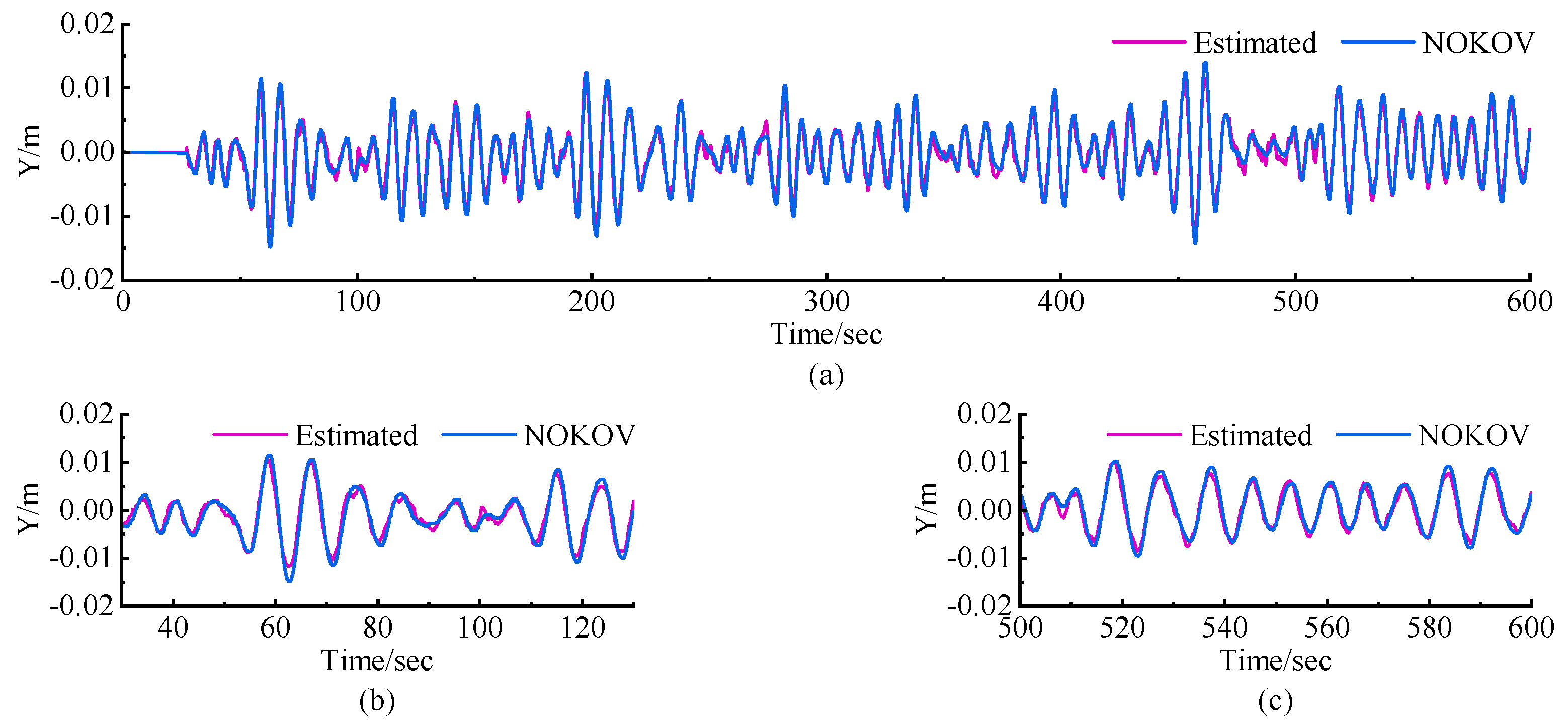
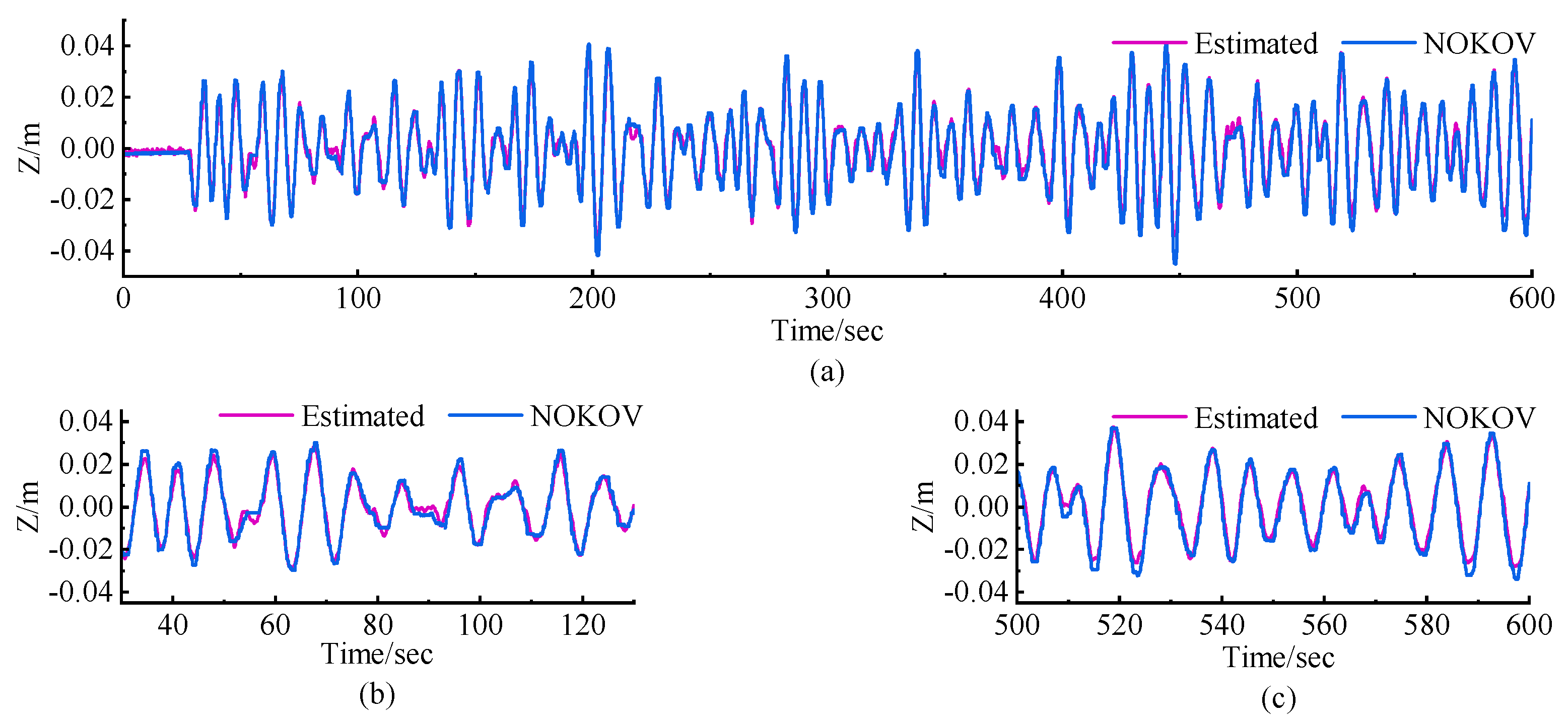
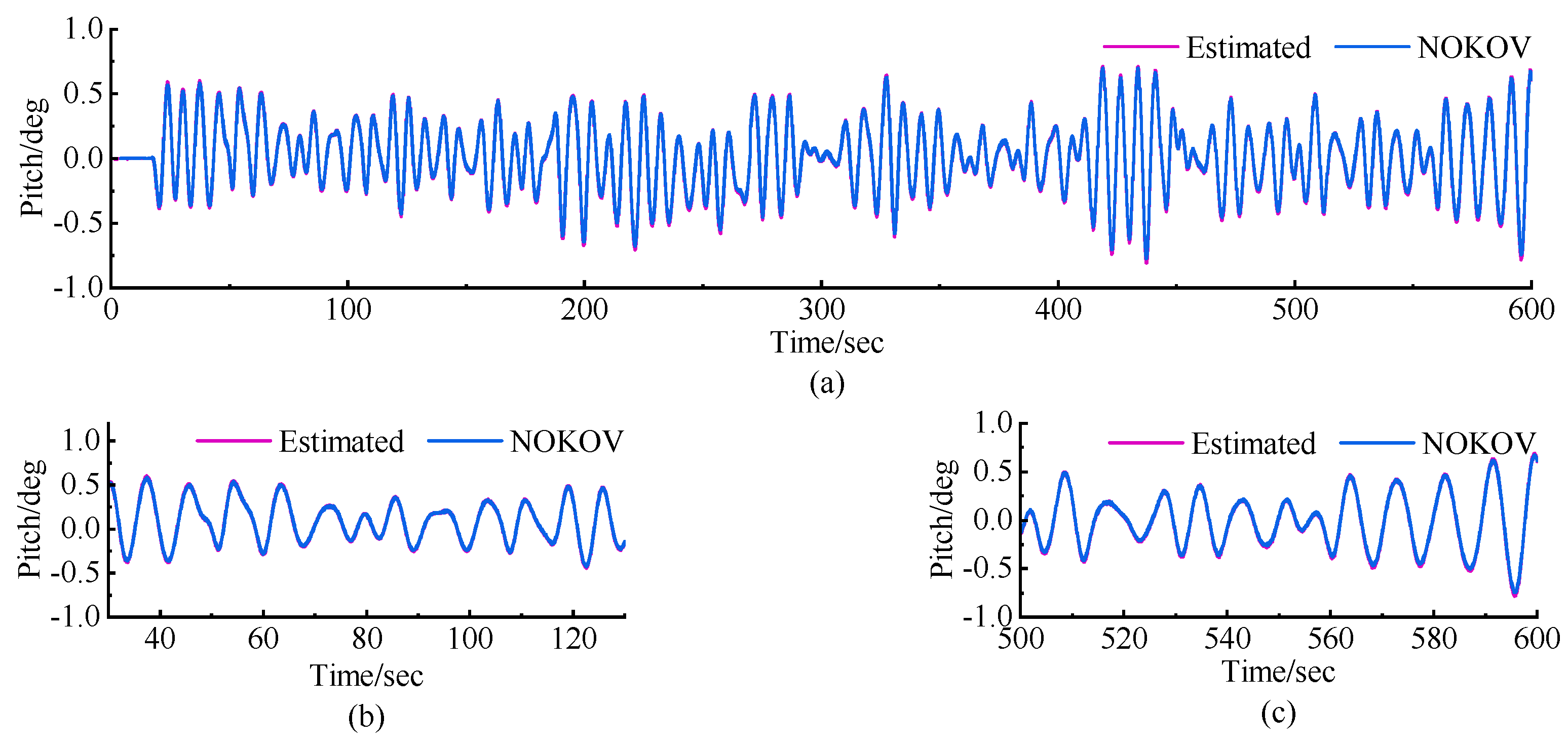
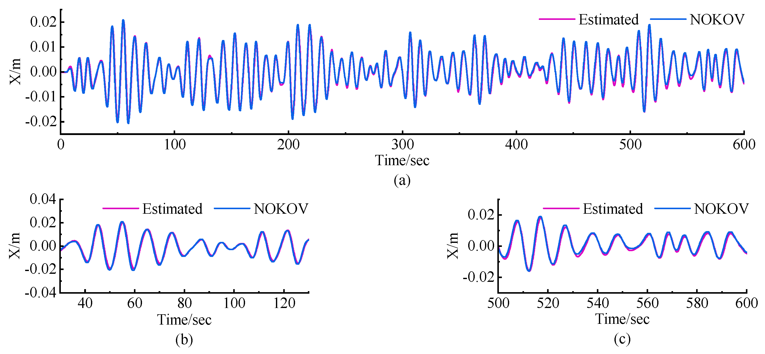
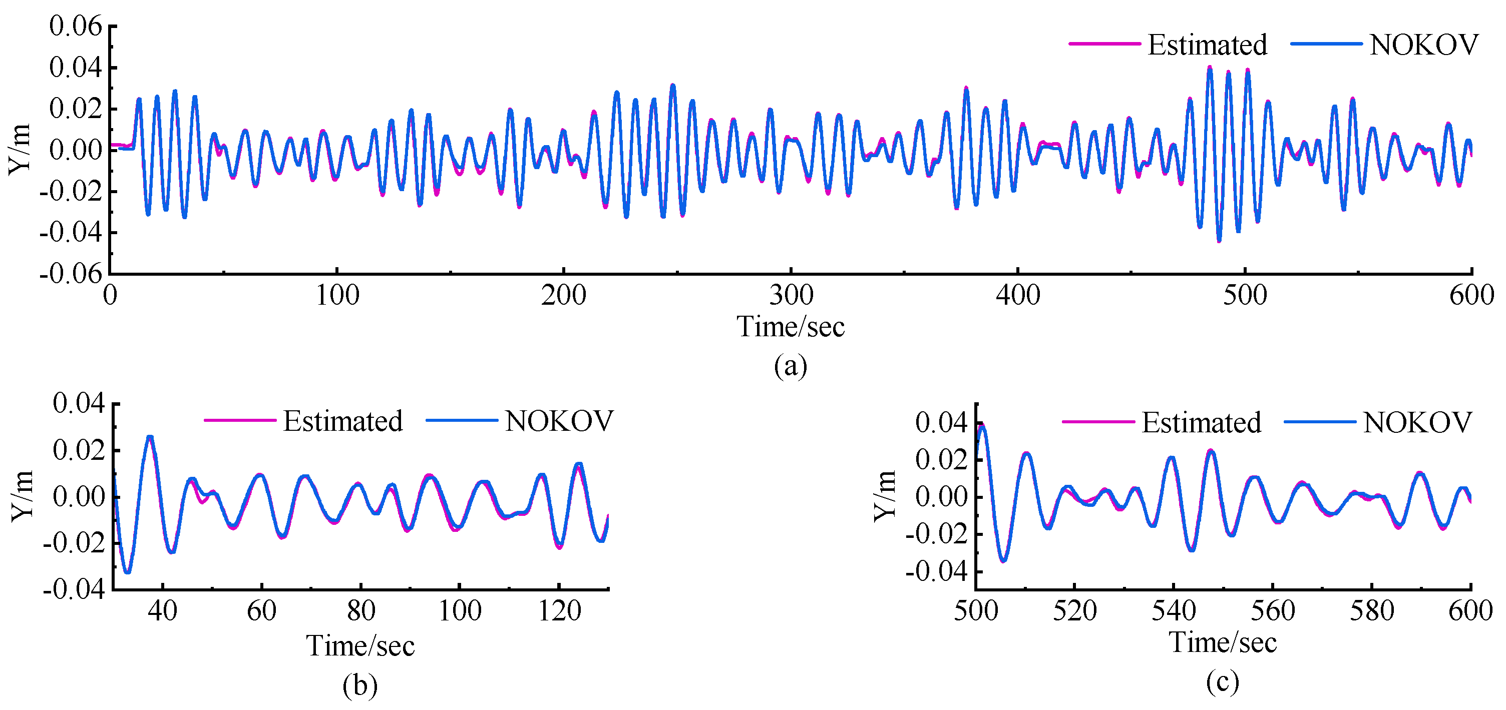
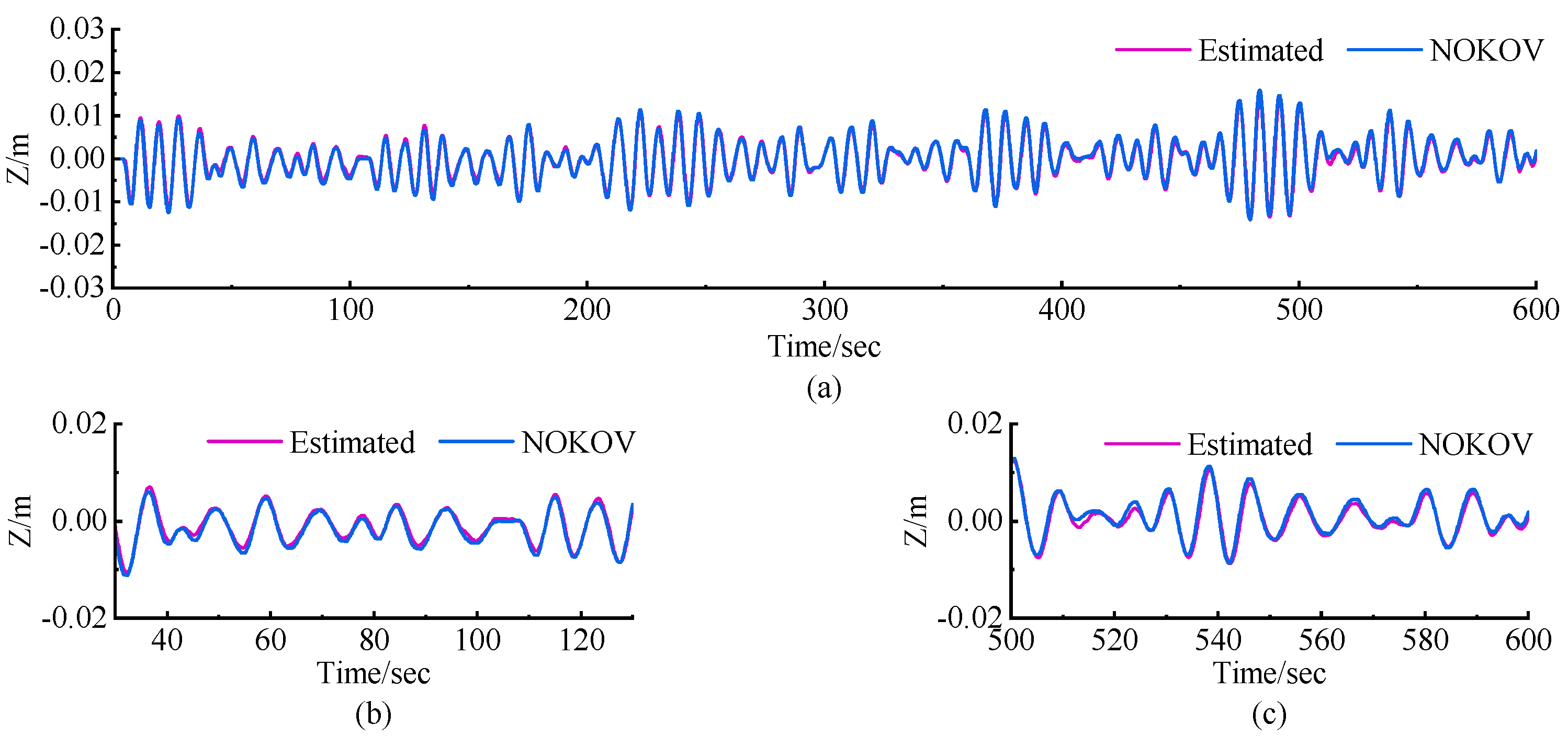
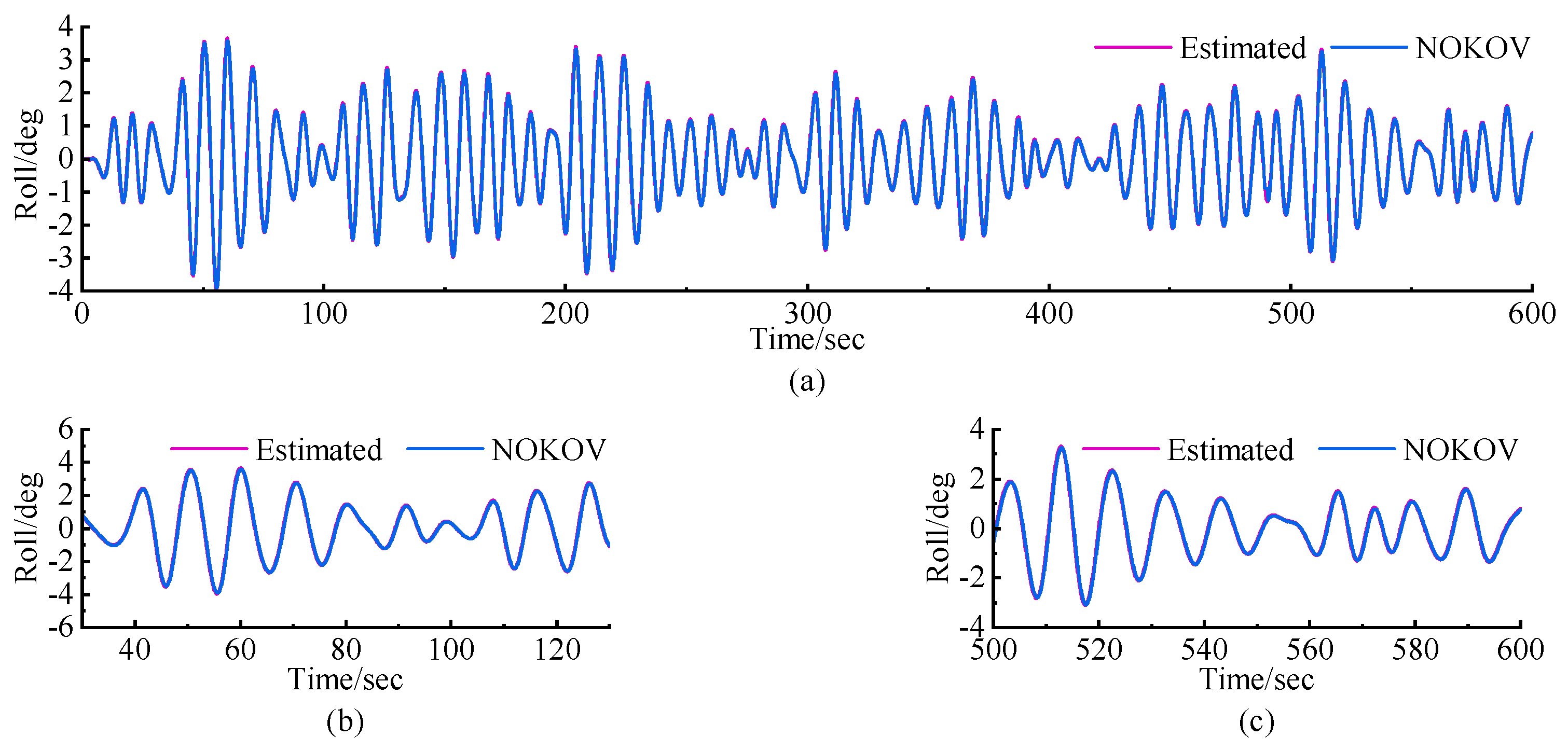
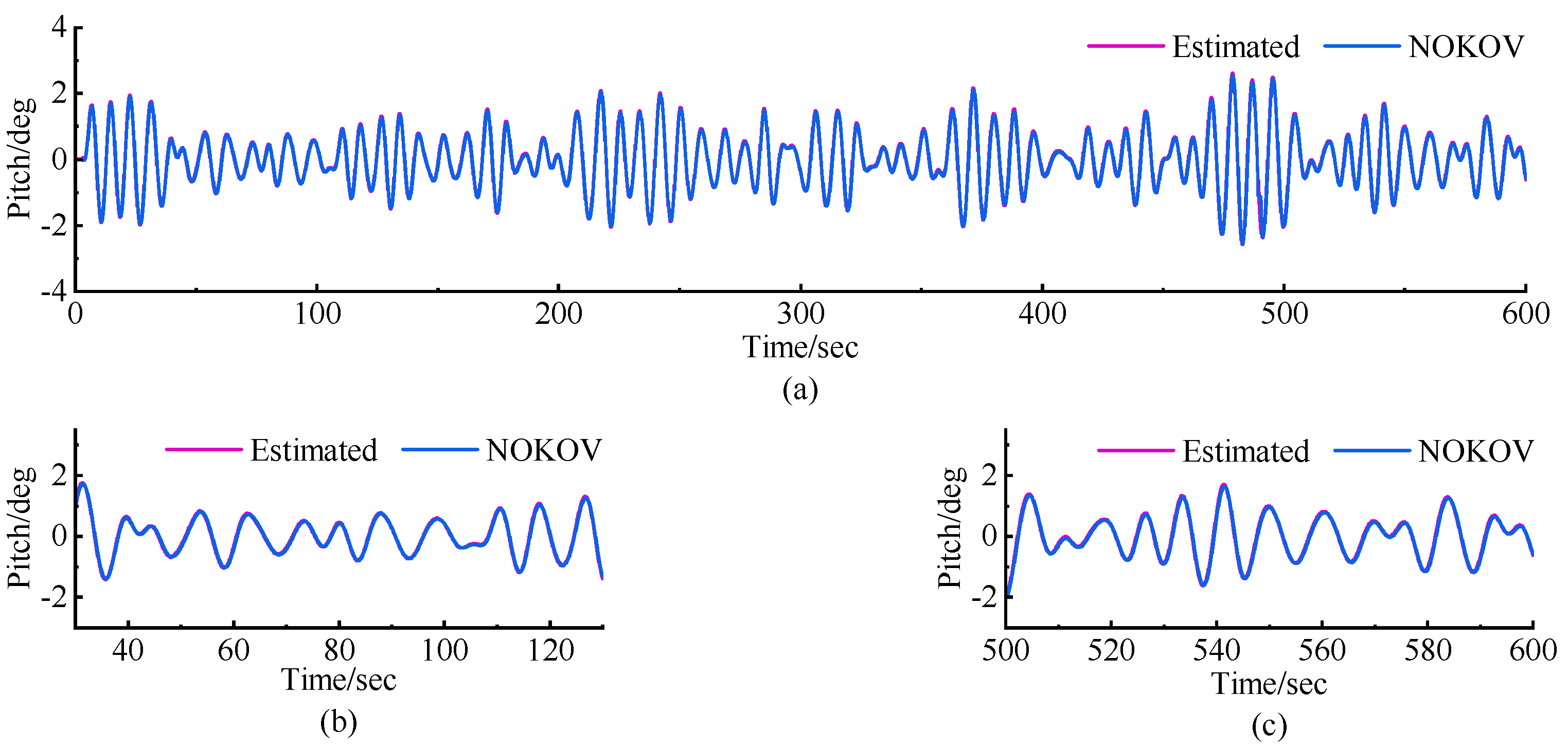
Initially, we used the MSS to simulate the ship’s motion under sea state level three, setting the corresponding wave height parameters in the MSS module. The experimental results are shown in
Figure 9,
Figure 10,
Figure 11,
Figure 12 and
Figure 13, where ‘Estimated’ represents the YOLO-based visual-inertial navigation detection system, and ‘NOKOV’ refers to the detection results from the motion capture system.
Table 4 summarizes the detection errors across different DOFs based on the differences in positional detections. The measurement error
was calculated using the following formula:
where
represents the data obtained by the YOLO-based algorithm across different DOFs and
signifies the data derived from NOKOV in various DOFs.
The measurement errors in the X, Y, and Z directions are less than 0.00135 m, 0.00343 m, and 0.00596 m, respectively. The roll angle error is less than 0.077°, and the pitch angle error remains below 0.043°. These errors demonstrate the system’s high accuracy, particularly in detecting positional information under the given experimental conditions.
A detailed comparison of the error data from the first 100 s and the last 100 s for the same target provides further insights into the system’s consistency over time. Specifically, the error in the X direction decreased from 0.00135 m to 0.00101 m, while the Y direction error significantly dropped from 0.00343 m to 0.00126 m. However, the error in the Z direction increased from 0.00281 m to 0.00564 m. For orientation measurements, the roll error slightly increased from 0.0409° to 0.0491°, while the pitch error rose from 0.009° to 0.018°. Although these increases are minor, they may indicate slight IMU data drift over time or potential influences from dynamic environmental changes. However, according to international standards, the overall error magnitudes remain within the acceptable range for maritime operations.
These results clearly demonstrate that the detection performance of the YOLO-based visual-inertial navigation system remains stable over time, without significant degradation. The minor fluctuations in error across different time frames and axes may stem from environmental factors or inherent limitations of the sensors, but they do not affect the overall robustness and reliability of the system.
Subsequently, we modified the wave height parameters in the MSS module and conducted validation experiments for the YOLO-based visual-inertial navigation system under simulated sea state level four. The experimental results are shown in
Figure 14,
Figure 15,
Figure 16,
Figure 17 and
Figure 18, comparing the detection results of the YOLO-based system (“Estimated”) with the motion capture system (“NOKOV”).
Table 5 summarizes the detection errors across different DOFs based on positional detection differences, calculated similarly to the previous experiments.
According to
Table 5, the measurement errors in the X, Y, and Z directions were less than 0.00455 m, 0.00417 m, and 0.00668 m, respectively. Meanwhile, the roll and pitch angle errors were less than 0.07° and 0.092°, respectively. A more detailed comparison of data from the first 100 s and the last 100 s for the same target revealed certain trends. The error in the X direction increased from 0.00049 m to 0.0014 m, the Y direction error increased from 0.0011 m to 0.0015 m, while the Z direction error decreased from 0.00258 m to 0.0015 m, indicating a slight decline in horizontal tracking accuracy in some directions over time.
For orientation measurements, the roll error decreased from 0.0558° to 0.0344°, and the pitch error decreased from 0.0548° to 0.0347°. However, it is worth noting that the pitch error, approaching 5%, has reached the upper limit allowed by international regulations. This suggests that while the system performs satisfactorily within the specified range, there is a limited margin for further error increase, especially under more challenging environmental conditions.
Compared to the performance under simulated sea state level three, the detection performance under sea state level four did decline, particularly in the X and Y axes and the pitch angle. This is expected, as more turbulent wave conditions impose greater challenges on the tracking system. Nevertheless, the performance remains within acceptable limits for maritime applications. These results highlight the robustness of the YOLO-based visual-inertial navigation system when handling more complex sea conditions. Future improvements should focus on enhancing stability under harsh conditions, potentially through advanced filtering techniques or increased reliance on inertial data during intense wave activity.
4. Conclusions
This study focuses on a motion compensation system for vessel-mounted cranes and introduces an innovative approach utilizing computer vision technology. The system performs real-time monitoring and analysis of motion during maritime equipment installation, enabling the detection of motion compensation values required for the ship. This advancement enhances the efficiency and safety of loading, unloading, and installation operations.
By utilizing Kalman filtering to integrate binocular vision and IMU data, a monitoring system for tracking the motion of loads has been designed. Techniques such as label detection, target tracking, and Kalman filtering were used to accurately capture the ship’s motion trajectory and attitude information. System validation and experimental evaluation were conducted in simulated marine operation scenarios using a Stewart motion platform and a simulated marine crane in a laboratory environment. The test results demonstrate that this detection method meets the requirements for monitoring the motion state of vessel-mounted crane loads under marine operational conditions, significantly improving the stability and accuracy of loading and unloading operations. Compared to traditional methods, this system exhibits superior performance in specific marine environments.
Although the method presented in this paper has yielded positive results in the experiments, there are still several issues that need to be further researched and resolved for practical application in real marine environments. First, the impact of detection distance on system performance is crucial. To ensure that the camera can capture targets clearly in real time under constantly changing working conditions, the system must maintain reliability across a wide range of distances. In marine environments, the distance between the crane’s target and the camera may change dynamically, which can lead to a decline in detection accuracy, requiring further optimization. Secondly, detection latency is another challenge that must be addressed. In future work, we plan to integrate a predictive module that forecasts future states based on historical data from the detection system, reducing errors caused by sensor delays and ensuring the system accurately reflects the real-time status of the target. Moreover, specific challenges in marine environments, such as varying lighting conditions, harsh weather, and vessel vibrations, can all impact the performance of the visual sensors. At the same time, the IMU may experience drift under extreme motion conditions, which could affect the accuracy of attitude measurements. Therefore, future research will focus on improving the robustness of the system. We plan to optimize the algorithms to enhance the system’s resistance to interference in different environments and to explore its performance with various types of loads, ensuring that the system remains stable and reliable in complex and dynamic marine environments.
The computer vision-based ship motion compensation detection system proposed in this paper provides a novel solution for marine crane loading and unloading operations. It not only enhances operational efficiency and safety but also reduces transportation losses and equipment maintenance costs. In the future, we will further optimize the system’s performance and expand its application scope in real marine environments.


 ,
, 


