Abstract
To advance wave energy devices towards commercialization, it is essential to optimize their design to enhance system performance. Additionally, a thorough economic evaluation is crucial for making these technologies competitive with other renewable energy sources. This study focuses on the techno-economic optimization of an innovative inertial system, the so-called SWINGO system, which is based on gyropendulum technology. SWINGO stands out due to its high energy efficiency in multi-directional installation sites, where wave directions vary significantly throughout the year. The study introduces the application of a multi-objective Evolutionary Algorithm (EA), specifically the Non-dominated Sorting Genetic Algorithm II (NSGA-II), to optimize the techno-economic performance of the SWINGO system. This approach aims to identify optimal design parameters that maximize energy extraction while considering economic viability. By deriving a Pareto frontier, a set of optimal devices is selected for further analysis. The performance of the SWINGO system is also compared to an alternative (mono-directional) inertial wave energy converter, the Inertial Sea Wave Energy Converter (ISWEC), to highlight the differences in techno-economic outcomes. Both systems are evaluated at two different installation sites: Pantelleria island and the North Sea in Denmark, with a focus on the directional wave scatter at each location.
1. Introduction
Global warming is severely impacting the health of our planet, primarily due to the rapidly increasing levels of CO2 in the atmosphere. Although activities such as livestock farming, transportation, and deforestation contribute to environmental harm, the rising demand for energy is a major factor [1]. In response, political entities are driving research toward new renewable energy sources. Significant advancements have been made in solar and wind renewable technologies over the past few decades, contributing greatly to global decarbonization efforts. Wind turbines and solar panels are well-established technologies, and are predicted to account for up to 90% of energy production by 2050 [2]. In this context, wave energy presents an additional solution for achieving carbon neutrality. Wave energy is a largely untapped resource with an estimated global potential of 2 TW [3,4,5]. It offers several advantages over solar and wind energy, including higher power intensity and greater predictability when confronted with sister renewables: wind is particularly unpredictable near the water surface, while solar power is influenced by cloud cover and the day-night cycle, especially at high latitudes. Despite these clear advantages, the harsh marine environment and the stochastic nature of waves make this resource challenging to be harnessed effectively.
Researchers have developed various concepts and architectures to exploit such an energy resource, including Point Absorber (PA) devices [6,7], flap-type WECs [8], and Oscillating Water Column (OWC) systems [9,10]. A further WEC class are the so-called Inertial Reaction Mass (IRM) devices, which are gaining popularity due to their ability to enclose all mechanical components within the floater, protecting them from the harsh marine environment. These devices also introduce an additional Degree-of-Freedom (DoF) in the energy conversion process, by incorporating a reaction mass inside the floater, allowing the exploitation of the hull’s rotational DoF. In this class of systems, the floater acts as a filter for wave motion, activating the internal reaction mass, which works as the prime mover for the Power Take-Off (PTO) apparatus. Specifically, IRM WECs can include various mechanisms, such as sliding masses, pendulums, and gyroscopes. The former solution is adopted by, for instance, the E-device [11], which converts the floater rotation through a prompting mass. Other devices, such as the vibro-impact WEC [12], enhance power absorption by exploiting nonlinear impacts. Moreover, pendulum-based WECs are categorized by the arrangement of rotational axes and the coupling between the inertial system and the WEC hull. Horizontal pendulums, like the PeWEC system [13], involve a pitching floater coupled with a swinging pendulum, while systems like the SEAREV [14,15,16] and WITT [17] employ eccentric masses for power generation. Alternatively, the pendulum can be arranged with a vertical rotation axis, mounted on an axial-symmetric floater, allowing for multi-directional coupling. The latter is the design of Penguin [18] and VAPWEC [19]. A further option are gyroscope-based WECs, such as the ISWEC [20], which relies on a spinning flywheel to activate the mechanism’s precession motion.
Recently, a novel and particularly convenient device, belonging to the family of IRM systems, has been proposed: the so-called SWINGO system [21]. This device introduces gyropendulum technology, able to combine and exploit the benefits from both pendulum and gyroscopic solutions, housed within an axially symmetric floater, coupled to an electric generator through a gear stage. Compared to any other sister IRM WEC, due to this innovative design, SWINGO can absorb wave energy from any direction, as opposing of being mono-directional (which is the case for, e.g., PeWEC and ISWEC), making it a highly efficient multidirectional system.
To achieve commercial viability, renewable energy devices must be evaluated based on both power performance and system cost, implying that any suitable optimization must be guided by techno-economic specifications [22]. Within [21], the choice of design parameters for the SWINGO system is based on Exhaustive Search (ES) algorithms, in which a set of device parameters is found by minimizing a simplified performance cost, taking into account power absorption for a particular wave scatter. While suboptimal, ES methods help in developing an optimized system architecture that enhances commercial competitiveness. Other examples of WEC optimization based on ES include, e.g., PA devices [23] and OWC systems [9,24,25]. Although ES approaches are suitable for preliminary analysis and to identify key performance trends, these can be limiting, especially for IRM WEC devices, since the integration of more advanced simulation hypotheses can be crucial for an efficient and effective design method, given their inherent complexity. For instance, devices like SWINGO require advanced simulation conditions from the early stages, including wave directionality (i.e., the direction of wave propagation relative to the device orientation), and multi-modal coupling, as the gyropendulum is primarily coupled with the roll and pitch DoFs of the floater. Therefore, incorporating such factors into the design simulation model is essential, in order to obtain an effectively optimal set of design parameters, able to guarantee maximum performance. For instance, this study is motivated by the consideration of seemingly secondary aspects, such as system directionality, from the earliest design stages. The goal is to ensure that optimization is informed by more advanced modeling of the wave resource, taking into account not only the frequency and power content of each wave condition, but also its directional distribution. This approach highlights the impact and advantages of multi-directional technology compared to systems that are inherently mono-directional. Motivated by the intrinsic advantages of the SWINGO concept as part of the IRM WEC family, and the benefit that can be obtained from an advanced optimization approach, this paper leverages Evolutionary Algorithms (EAs) for a multi-objective optimization of the SWINGO system. These global optimization codes, based on evolutionary theory and the survival-of-the-fittest principle, have recently gained popularity in the wave energy field [22]. As illustrated within this paper, this class of algorithms is particularly effective for IRM devices, which involve parameters related to the floater, internal reaction mass, and coupled PTO system, generating a vast search space that a genetic algorithm can efficiently handle. The non-dominated sorting genetic algorithm II (NSGA-II) is chosen within this study [26] to solve the optimization based on a multi-objective performance criteria. This algorithm is designed to identify a set of Pareto optimal solutions, which are solutions that are not outperformed by any other feasible options. Note that such a method has been applied for optimizing the ISWEC system, considering both the mechanical PTO and hydraulic PTO systems, in [27] and [20], respectively.
To be precise, within this paper, a techno-economic optimization of the SWINGO system is fully developed and explored, considering a comprehensive design space with high dimensionality, encompassing up to 12 design variables, including the shape and dimensions of the floater, ballast and inertial properties, gyropendulum properties, PTO rated torque, velocity and power, and gearbox speed conversion ratio. Moreover, realistic geometrical, technical, and structural constraints are implemented based on sub-component characteristics. The objective function is defined by minimizing capital cost and maximizing the Annual Energy Productivity (AEP). This expanded approach allows for a more comprehensive optimization of the WEC technology, taking into account both performance and economic factors. To evaluate this feature, the system’s performance is tested and compared across two different installation sites with distinct wave direction characteristics: Pantelleria island in the Mediterranean Sea, where waves predominantly come from a single direction throughout the year, and the North Sea on the Danish continental shelf, where wave directions are more diverse and variable.
The remainder of this paper is organized as follows. Section 2 introduces the main characteristics of the SWINGO device, highlighting its differences compared to the benchmark sister WEC technology, i.e., the ISWEC. Section 3 presents the mathematical model used for evaluating the SWINGO system’s performance. Section 4 details the selection of the sites of interest, presenting the directional scatters and wave clustering used for the numerical simulation of the wave resource. Section 5 introduces the multi-objective optimization problem for WEC systems. Section 6 describes the SWINGO parameterization procedure, and focuses on the optimization problem specific to this system. Section 8 presents the Pareto optimal solutions, and compares them with those of the ISWEC, providing a critical analysis of a restricted family of devices. Finally, Section 9 encompasses the main conclusions of this manuscript.
2. SWINGO Technology
This section introduces the SWINGO technology, whose optimized architecture is the main subject of this paper. Following the discussion provided in Section 2, the optimization results for the SWINGO system are compared to those of the ISWEC technology, which is the benchmark device due to its similarity, since it is based on the gyroscope mechanisms [20]. Both technologies are outlined to highlight their key features and assess their suitability based on the characteristics of the installation sites used as case studies.
2.1. Working Principle
SWINGO, developed by the Department of Mechanical and Aerospace Engineering at Politecnico di Torino, is an IRM WEC based on so-called gyropendulum technology. In particular, a sealed floater houses all of the electrical and mechanical components, protecting them from the harsh marine environment. A 1:20 scale prototype of the SWINGO system is shown in Figure 1, illustrating its main components. The floater is moored to the seabed using a four-leg mooring system [28], which is essential for maintaining the stability and the station-keeping of the floater, ensuring it can effectively respond to wave impacts for energy harvesting. For instance, when waves impact the hull, a rotational motion around a general axis within the -plane is induced, as referred to in Figure 2. This rotation activates the gyropendulum mechanism within the hull, which is directly coupled to the PTO system. In particular, the SWINGO device operates using a mechanical conversion apparatus [29], where a gear stage connects to an electric generator. Therefore, the gyropendulum drives the mechanical PTO system, converting the mechanical energy from the wave-induced motion into electrical energy. The innovative use of a gyropendulum in this context allows the system to efficiently harness wave energy, regardless of the specific axis of floater rotation within the -plane, providing a robust solution for energy conversion in a marine setting.
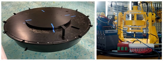
Figure 1.
Pictures of the 1:20 SWINGO prototype: hull picture in a water tank for hydrostatic tests (left), gyropendulum picture (right). The device was developed by the Politecnico di Torino, Department of Mechanical and Aerospace Engineering.
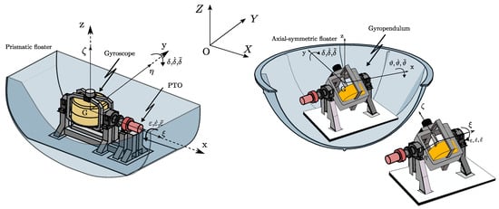
Figure 2.
Qualitative representation of the IRM involved in the analysis: the ISWEC (left) and the SWINGO (right).
Specifically, the gyropendulum is a gyroscope whose rotor is placed at a certain distance from the precession axis. The technical solution presents a single mechanism that, with the described characteristic, is capable of functioning both as a pendulum and as a gyroscope. In particular, its functionality varies based on the oscillation imposed by the external environment. As shown in Figure 2, this device consists of a flywheel free to rotate about its polar axis and connected to the gyroscopic structure or gimbal via a pair of mechanical bearings. The gyroscopic support is free to rotate about its axis , which is called the precession axis of the mechanism, and the rotation angle is defined by the coordinate. This axis coincides with the axis of the electric generator, which extracts energy by braking the motion induced on the gyroscope support.
SWINGO is a WEC design suitable for absorbing energy in a location where waves come from various directions. For instance, referring to Figure 3, three operational conditions can be identified for this technology, based on the incoming wave direction:

Figure 3.
Schematic representation of SWINGO conversion principle.
- Wave direction : The floater rotates at an angle relative to the y-axis, activating the pendulum system with the flywheel rotating at a constant speed . In this configuration, the gyropendulum is excited only by gyroscopic forces.
- Wave direction : The floater rotates at an angle relative to the x-axis, activating the gyropendulum with rad/s. Here, the system is excited solely by elastic forces, with no gyroscopic effect, as it is constrained along the y-axis.
- Wave direction : The floater rotates obliquely, causing combined rotations around the x and y axes. In this case, the gyropendulum is excited by both the elastic force due to the restoring mass and the gyroscopic effect.
Given the unique multi-directional characteristics of the SWINGO system, an accurate modeling of the wave’s arrival direction in the plane is crucial, as it significantly affects the system’s response. Further details about the SWINGO system are reported in [21].
2.2. Benchmark Technology: The ISWEC
In this section, a particular focus is reserved to the ISWEC device, used as a benchmark IRM WEC in this paper, for comparison. Although the ISWEC floater is prismatic, it can align itself with the incoming wave direction through a suitable mooring configuration (see, e.g., ref. [30]). The ISWEC system is based on gyroscope technology, which is installed in an floating hull. With reference to Figure 2, according to the floater hydrodynamics, the ISWEC system is allowed to rotate with respect to its y-axis, with a pitch rotation (as in, e.g., ref. [20]). Such motion activates the gyroscopic system, which is induced to oscillate according to an angle , due to the forces generated by the incoming wave field (see, e.g., ref. Figure 2). Such gyroscopic motion is then converted into electrical energy by means of a PTO system. The generation axis couples the gyroscopic unit to an electric generator through a mechanical gearbox. Two radial roller bearings and a couple of spherical thrust bearings are mounted to support both axial and radial loads of the gyroscope. Bearings are lubricated and cooled down through suitable hydraulic circuits.
The ISWEC concept was drawn up and then developed by the renewable energy research group of the Department of Mechanical and Aerospace engineering at the Politecnico di Torino in 2005. The first tests on the ISWEC system were performed on a proof of concept, with a rated power of W, to verify the system capabilities and the gyroscope response as a function of the floater pitching angle. In 2015, the first full-scale ISWEC device was installed offshore to the Pantelleria island, belonging to the Sicily region in Italy. Pictures of the actual prototype tested offshore to Pantelleria island are shown in Figure 4. Note that, to counterbalance the gyroscope reaction force on the floater and prevent undesirable torque that induces rolling motion along the x-axis, the ISWEC system incorporates two counter-rotating gyroscopes inside its floater, i.e., two PTO systems.

Figure 4.
Full-scale ISWEC device during the installation phase (right) and gyroscope mounting process (left). The device was developed by the Politecnico di Torino, Department of Mechanical and Aerospace Engineering.
Table 1 compares the ISWEC and SWINGO systems, highlighting that the ISWEC, due to its floater design, functions as a pitching technology. Its gyroscope system is activated exclusively by floater oscillations along the y-axis. For this technology, mooring is a critical component, as it must allow the floater to self-align with the incoming waves. In contrast, the SWINGO is designed to intrinsically overcome this issue. The mooring system’s primary role is to keep the floater in place, as wave directionality does not significantly impact the system’s performance. This is due to the floater’s shape and the multi-axial coupling enabled by the gyropendulum technology.

Table 1.
Comparison between the ISWEC and SWING technology.
3. SWINGO Modeling and Simulation
This section recalls the modeling approach adopted for the SWINGO system in linearized conditions. The reader can refer to [21] for a detailed derivation of a nonlinear counterpart.
3.1. Mechanical Interactions Model
In this section, we recall the fundamental mathematical model describing the dynamics of the SWINGO device, starting from the gyropendulum mechanism. In particular, the latter can be schematized as composed of two a equivalent rigid body: the gimbal, with a mass , and the flywheel, with a mass . We subsequently define the corresponding inertia matrix of each body characterizing the gyropendulum device as follows:
where are the inertia matrix of the gimbal and flywheel system, respectively. It is worth highlighting the existence of several reference frames, defined for the system dynamics description. In particular, the wave induces a motion on the hull in the body-frame , generating a gyropendulum motion through the hinge, defined in the set of Cartesian axis.
As discussed previously, his section focuses on deriving a representative linear model for the SWINGO system, under the assumption of small roll and pitch rotation. For the sake of simplicity of exposition, we assume that the yaw rotation is null, as no relevant dynamics arise in such a DoF (see [21]). Let , , be the vector describing the position and orientation of the hull, where , and describe surge, sway, and heave motions of the floater, respectively. In addition, there is a sixth DoF, describing the relative gyropendulum motion concerning the floater, being connected to the PTO axis, described by , and we can hence now define an ‘augmented’ vector , . In linear conditions, the dynamics of the SWINGO device can be described in a compact form through three different matrices, i.e.,
where , is the total external force acting on the system, while the matrices , and define the coupling between the gyropendulum and the hull, providing the mathematical representation of the inertial reactions, gyroscopic, and restoring force due to the interaction between bodies. The linearized system matrices are defined as follows:
where is the position of the gyropendulum unit with respect to the floater Center-of-Gravity (), , is the total gyropendulum mass, g is the acceleration due to gravity, and is the flywheel distance from the precession axis. Finally, the so-called excitation vector is defined as
where is the control law, which has to be designed such that maximum energy absorption is achieved.
3.2. Modeling of the Floater Dynamics
The floater is not directly involved in the energy conversion process, but it is the main component that transfers wave energy to the inner inertial system. Therefore, the wave–hull interaction dynamics must be modeled through a suitable mathematical framework. Modeling of the IRM system includes fluid–structure interactions and the characterization of mechanical coupling matrices. As discussed previously within this section, the floater’s motion is the prime mover for the gyropendulum, which reacts by means of the external forces that affect the floater’s dynamics. This interaction is crucial for the energy extraction process.
Assuming an incompressible fluid and irrotational flow, linear potential flow theory [31] is used to approximate fluid–structure interaction via a time-domain system of Volterra integro-differential equations for :
where is the derivative of the floater’s pose, coinciding with its velocity vector in planar motion. defines the uncontrollable wave excitation force [32], is the gyropendulum reaction force, and is the radiation force. The generalized mass matrix of the hull, , is referred to the frame. The hydrostatic restoring force, , is proportional to the pose of the floater and can be written as , where is the hydrostatic stiffness matrix. The radiation force is modeled using Cummins’ equation [33]. The radiation force on the i-th degree-of-freedom is defined as:
where is the so-called added-mass at infinite frequency, due to the water displaced when the body moves, while the second term corresponds to the dissipative force, linear with respect to the body’s velocity, computed in terms of a convolution operator with respect to the impulse response kernel .
3.3. Mechanical Coupling
Equation (5) describes the dynamic equation of motion for the floater, which we now link with the gyropendulum-generated reaction forces, as previously outlined in Equation (2). Therefore, the system equations in compact form, enclosing the interactions between the incoming wave and the PTO, can be expressed through the following system, for ,
where and represent the corresponding insertion (let ; the insertion of an element in is simply ) of the matrices and in , respectively. Analogously, , and correspond to the insertion of the hydrostatic, wave excitation and radiation force vectors in , respectively. It is important to note that, given the inertial nature of the system, the equation of motion is influenced by both hydrodynamic forces and the forces arising from the mechanical coupling between the inertial mass and the floater. Further details on Equation (7) are generally provided for wave energy systems and specifically for inertial systems in [21,34].
3.4. Gyropendulum Frequency-Response Function
This section introduces the frequency-domain (FD) equation of motion characterizing the gyropendulum, by applying the Fourier transform to Equation (7). As discussed further within this section, the FD simulation fundamentally differs from the time-domain (TD) approach, as it relies on a probabilistic model of the system dynamics. Instead, TD models of WECs use classical methods to solve the equations of motion using a deterministic model. A deterministic model involves defining a specific wave that excites the WEC, to solve for the corresponding motion. However, in contrast, a probabilistic model uses a statistical representation of the waves, which when passed through an appropriate transformation function, produces a probabilistic estimate of the WEC response. When the dynamics of the WEC are represented linearly (as per the derivations within this section), its steady-state response to an input composed of frequency components is the sum of the responses to each individual component. This leads to a representation of (7) in the FD as follows:
where , and , are the Fourier transform of the displacement vector p and wave elevation , respectively. Furthermore, the matrix represents the Fourier transform of the matrix , i.e., the insertion of in . The notation is reserved for the frequency-response map between the wave profile and the resultant excitation force , while represents the external (control forces), parameterized in terms of a generic feedback law . From Equation (8), the frequency-domain characterization of the map can be computed in terms of the response matrix:
3.5. Frequency-Domain Simulation
Every WEC system can be simulated, considering that the output of a linear system driven by a Gaussian process is a Gaussian process itself. The assumption that the response is also Gaussian is known as Gaussian closure [35]. Therefore, if the stochastic nature of the wave elevation can be described by a corresponding power spectral (PSD) density function , which is defined within this study through the JONSWAP spectrum [32], the PSD matrix of the response q is obtained by the following relation:
where is the PSD associated with the WEC motion response and denotes the Hermitian transpose of .
3.6. Control Synthesis
Specifically, the useful energy absorbed from incoming waves is converted in the PTO system and can be computed as the time integral of the converted instantaneous power. Therefore, the total absorbed mechanical power can be expressed as
where corresponds to the simulation time, and is the associated instantaneous mechanical power. Note that the design of falls under the umbrella of optimal control problems (OCPs). Optimal control design for WECs involves an energy-maximization criterion, with the objective of maximizing the absorbed energy from ocean waves over a finite time interval . In particular, the control structure, considered within this manuscript, generates an action defined by the PI control, which is often referred to as reactive control due to the presence of the derivative term. This is because the corresponding electric generator can potentially behave as a motor, resulting in a bi-directional power flow. Such a reactive controller is characterized in terms of the following relation:
where and are the corresponding control parameters. Therefore, according to the definition introduced in Section 3.4, the mapping matrix is defined as follows:
The optimal set of parameters for the PI controller can be obtained through numerical optimization techniques, for maximizing WEC energy extraction. Applying Equation (12), the absorbed mechanical power can be computed as follows:
It is worth noting that when the signal is zero mean, the expected value of the square of the signal, i.e., , corresponds to its variance. Therefore, the power is computed as follows:
where and are the variance and the PSD function, respectively, associated with the actuated DoF in line with Equation (10).
3.7. Performance Evaluation
So far, power computation is purely performed in terms of gross power; nonetheless, the SWINGO system presents a set of sources of losses, discussed in the reminder of this section. The losses in the system play a significant role in determining the optimal configuration of the SWINGO device, particularly due to their impact on the flywheel velocity, . While increasing the flywheel velocity can enhance the system’s performance by increasing the gyropendulum momentum, it also introduces losses due to the contact between the shaft and its support, i.e., the bearings. These losses should not be overlooked, as they can affect the overall efficiency and power output of the SWINGO system. On the basis of this, the net power can be defined from the mechanical power, generated by the motion of the gyropendulum system, as follows:
where represents the total power losses during the power transformation process. According to the general architecture of the gyropendulum system, the main sources of losses can be defined [36]. Within this paper, the three most significant sources of losses are introduced: power losses, attributed to the flywheel support bearing; losses resulting from the efficiency of electric components; and losses due to baseloads. In particular, these are characterized as follows:
- Bearing losses. The gyropendulum flywheel is supported by three spherical roller bearings, enabling its rotation around the -axis. The configuration adopted relays on a pair of radial bearings to handle radial loads, while the axial loads is supported by a single spherical roller bearing. According to the simulation model adopted in this study, the focus is kept on the scenario where the flywheel operates at a constant speed, and hence loads resulting from flywheel acceleration are not considered. The bearing losses are calculated using the model provided by the supplier SKF model (the reader can refer to [37] for further details).
- Electric losses. In the SWINGO system, the energy captured from the PTO is extracted through an electric generator, specifically a Permanent Magnet Synchronous Generator (PMSG), which is equipped with a converter for grid connection to enable variable speed control. The torque of the generator is regulated by an inverter. For the purposes of this manuscript, synthetic values of electric efficiency are employed as a preliminary approximation, given by for the PTO system. This efficiency value is initially estimated based on the values provided in [38]. Therefore, the power loss resulting from this efficiency can be simply computed as follows:
- Baseloads losses. The SWINGO device is equipped with several auxiliary subsystems that ensure the proper functioning of the main components, involved in the power conversion principle. For instance, a cooling system for electrical and mechanical equipment is required, as well as the power supply for electronics and data acquisition systems. As such, the baseloads consist of two main components. Firstly, there is a cooling system and oil circuit for power lubrication of the support bearing of the flywheel, which accounts for a power requirement of approximately 2 kW. Additionally, there is a power demand of kW to manage all of the power electronics, such as super-capacitors and batteries. As a result, the baseload losses being considered are precisely defined as follows:It is worth noting that, as indicated in Equation (18), the baseloads power losses are dependent on the flywheel speed. When the system operates as a pendulum with, i.e., rad/s, the cooling and lubrication requirements for the bearings are not necessary. In this scenario, the losses due to baseloads can be quantified simply as kW.
4. Multi-Directional Wave Scatter
This section aims to introduce the sites of interest, in terms of the characterization of the wave resource for two selected locations. For the upcoming analysis, i.e., results in terms of performance and productivity of the proposed IRM WEC devices, it is relevant to describe the installation site in terms of overall available energy, occurrences, and power associated with each wave. A high relevance is reserved to the study of the directionality of each wave in the scatter table, since it can impact significantly the power extraction.
4.1. Main Characteristics of the Installation Sites
The characterization of the installation site is a key step for the performance evaluation of WEC system. It is commonly characterized in terms of a semi-enclosed sea with a medium wave energy power, with a broadband energy distribution, concentrated in a low-medium frequency range. Such a installation site is suitable for directional devices, e.g., device characterized by a prismatic floater, as the ISWEC system [20]. According to [39], the Mediterranean Sea is less energetic than oceanic sites, but also presenting less dangerous extreme conditions. In particular, the targeted installation site of the ISWEC device (see Section 2.2) is near Pantelleria island in the Mediterranean Sea.
If Pantelleria island represents an example of a mono-directional wave scatter, the North Sea, in contrast, is characterized by a multi-directional wave rose. The North Sea is an inland sea of the Atlantic Ocean in Northwestern Europe, with an average water depth of 94 m. The North Sea is located between the European Continent (Denmark, Germany, The Netherlands, Belgium and France), the Scandinavian peninsula (Norway), and the UK, and it is 575,000 km2 in size [40]. The specific installation site selected is close to mainland Denmark. In particular, on the Danish Continental Shelf, the resource is varying from 7 kW/m near the coast to 17 kW/m far from shore (150 km). The presented Wave data has been obtained directly from the ERA5 database [41]. We note that the wave climate in the North Sea is less aggressive compared to open seas, and therefore more likely to assure the survivability of WECs. The wave roses presented in the following are based on the assumption that wind and wave direction coincide, in line with the assumption that most of the waves are classified as wind induced waves [42]. Figure 5 shows that the selected site in the North Sea is highly multi-directional, in terms of occurrences: the most frequent direction, being the north-west sector, is characterized by of the whole occurrences, but from the north to the south-west, at least 15% of the yearly occurrences are contained. The main data are summarized in Table 2.
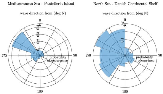
Figure 5.
Wave roses of the two referenced installation site: the Mediterranean Sea (left) and the North Sea (right).

Table 2.
Characterization of the selected installation site: Mediterranean sea (Pantelleria island) and the North Sea (Danish Continental Shelf).
4.2. Clustering of Wave Directions
To facilitate the analysis, the wave data for both installation sites have been grouped into four equivalent principal directions: 0°, 30°, 60°, and 90°. These directions correspond to specific sectors represented in Figure 6 and Figure 7. Table 3 provides information on the most recurrent and most energetic wave periods associated with each sector. This allows for a streamlined understanding of the wave characteristics and helps in evaluating the performance of the WEC devices in different wave conditions. Table 4 shows the annual energy associated with each sector in terms of absolute value or percentage distribution.
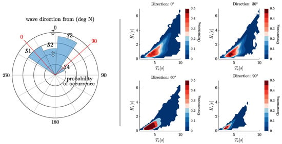
Figure 6.
Diagram of the wave clustering according to the direction (left) and occurrence (right) scatter diagrams for the reference close to Pantelleria island, Italy.
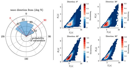
Figure 7.
Diagram of the wave clustering according to the direction (left) and occurrence (right) scatter diagrams for the reference site in the North Sea, in the Danish Continental Shelf.

Table 3.
Characterization of the proposed sea site is terms of the most energetic and the most recurrent period.

Table 4.
Characteristics of the installation site about the four sectors.
5. Definition of the Optimization Procedure
Having defined the fundamental elements of the SWINGO system, this section explores the optimization procedure, including the selection of key WEC parameters and the formulation of the optimization problem for the WEC system. The discussion is kept general on purpose, as it represents an initial approach to address the multi-objective optimization problem.
5.1. Optimization Problem
This section aims to introduce the optimization problem for WEC systems, in terms of a general program . In particular, this can be formulated as follows:
where represents the design parameters in the design space, , is the cost/performance function, which, in general, cannot be expressed in an explicit algebraic form, but can be numerically computed. Note that determines the dimension of the optimization variable, and denotes the number of objectives. Moreover, and represent a set of equality and inequality constraints, often related to the dynamical equation describing the WEC motion, and parameter bounds and any physical limitation to be guaranteed for safety of operation, respectively. In particular, the optimization process for WEC systems aims to address the following points:
- Modeling fidelity and computational resource availability: The optimization process should consider the level of fidelity in the mathematical models used to represent the WEC system, which are reflected via the mapping . This includes the accuracy of models and control system synthesis.
- Properties of the optimization problem: The optimization problem can be a continuous or discrete problem, depending on the nature of the design parameters. It can involve single or multiple objectives within the map F, where multiple conflicting objectives need to be balanced.
- Property of the design space: The design space refers to the range of possible values for the design parameters. The design space can have local optima or discontinuities, according to both maps and .
- Constraint handling: The optimization process needs to handle the constraints associated with the WEC system, reflected via . These can include physical constraints, such as limitations due to the hardware, as well as operational constraints, such as maintaining a certain level of power output or satisfying dynamic performance requirements.
5.2. Optimization Algorithm
As preliminarily discussed within Section 1, the multi-objective algorithm selected for such WEC application is the NSGA-II. The NSGA-II algorithm [26] is ideal for multi-objective optimization, as it generates a diverse set of Pareto-optimal solutions, balancing conflicting objectives. Its fast non-dominated sorting and crowding distance mechanisms prevent premature convergence, making it well-suited for optimizing complex systems like SWINGO. The NSGA-II algorithm is based on the standard operators of genetic algorithms selection, reproduction, crossover and mutation. The main steps of each generation are outlined in Figure 8, and hereafter introduced. These can be summarized as:
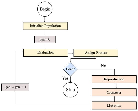
Figure 8.
Representation of the NSGA-II iteration scheme.
- 1.
- Initialization: generate an initial population of random potential solutions.
- 2.
- Evaluation: assess the fitness of each solution based on defined objective functions.
- 3.
- Non-dominated sorting: sort solutions into non-dominated fronts according to Pareto dominance.
- 4.
- Crowding distance calculation: measure the diversity within each front to maintain a wide range of solutions.
- 5.
- Selection and reproduction: select individuals based on their rank and diversity to form the next generation, using crossover and mutation to generate new solutions.
The NSGA-II algorithm iterates through these steps, creating new generations of solutions and gradually improving the population towards the Pareto front, which represents the set of optimal solutions. The final output of the algorithm is a diverse and well-distributed set of Pareto-optimal solutions that can be analyzed to make informed decisions in multi-objective optimization problems.
During the selection phase, the solutions are ranked based on their position relative to the best Pareto, built based on the crowding distance method [26]. In this study, the Matlab variant (gamultiobj function, Matlab version 2021b) of the original NSGA-II has been adopted, knowing that it introduces controlled elitism of the solutions. A controlled elitist algorithm increases the diversity of the population and avoids premature convergence in local minima. The default crossover and mutation functions have been changed in order to improve the efficiency of the code. The bounded exponential (BEX) crossover and power mutation (PM) have been adopted as they have proven effective applied in many nonlinear mixed-integer constrained optimization problems [43]. In particular, the NSGA-II has been set with the features presented in Table 5. Regarding the truncation procedure, the selection is based on the Shapova method. Note that the tuning factors of the algorithm are summarized in Table 6. Note that the code has been parallelized for computational efficiency. Specifically, each generation is run concurrently by assigning each individual to a separate core of a high-performance computing (HPC) system with 75 cores, powered by Intel Xeon Platinum 8160 processors, Intel (Santa Clara, CA, USA). Given that a single individual takes approximately 420 s for the full scatter simulation, the entire optimization process lasts around 17.5 h.

Table 5.
NSGA-II: genetic algorithm features.

Table 6.
Tuning parameters of the genetic algorithm.
6. SWINGO System Parameterization
The SWINGO system consists of three primary subsystems: the floater, the gyropendulum, and the PTO system. Each subsystem is defined by multiple parameters, which serve as the “genes” to be optimized in the multi-objective optimization process. These parameters determine the overall configuration of the SWINGO system, enabling the development of an optimized design, tailored to specific performance goals.
6.1. Characterization of the Floater System
The floater is a critical subsystem of the SWINGO device, as it is responsible for transferring power from the waves to the inner mechanical system. The hull of the SWINGO system is constructed using standard naval carpentry steel, which has a density of kg/m3. The SWINGO floater is axially symmetric, hence obtained by a surface revolution with respect a vertical axis. On this purpose, Figure 9 illustrates the floater profile in the plane. To be more specific, the surface within the positive axis plane is revolved around the z-axis, resulting in the creation of an axially symmetric floater.
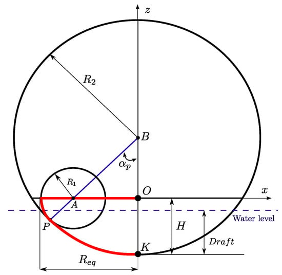
Figure 9.
Parametric curve definition of the SWINGO profile on the plane.
In particular, as detailed in Figure 9, the device can be characterized according to the following set of parameters:
- : semi-length of the floater.
- : total length of the floater.
- : radius of circumference .
- H: overall height of the hull.
- : radius of circumference .
- : tangency angle .
Note that the hull profile is parameterized through simple curves: the bottom circumference, traced from point B, intersects the rim in the bow/stern section at the tangential point P. Moreover, a subset of independent geometrical and inertial parameters can be defined as follows:
- k: height ratio .
- h: bow/stern circumference ratio .
- BFR: Ballast filling ratio, defined as the ratio of ballast located in the aft/fore ballast tanks over the total ballast (note that a indicates that all the ballast is stored in the aft/fore ballast tanks, while indicates that the totality of the ballast is stored in the bottom ballast tank)). Note that the density for the concrete ballast is kg/m3.
For instance, Figure 10 shows the impact of the shape parameters h and k, keeping the same value for the remaining ones. Figure 11 shows the impact of the ballast distribution parameter .
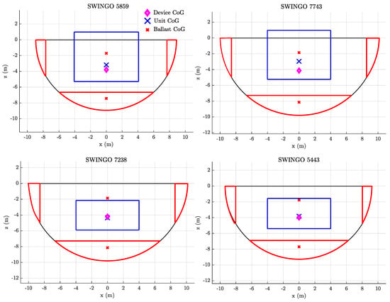
Figure 10.
Example of hull profiles for different values of k and h.

Figure 11.
Example of ballast mass distribution between the bottom and the deck compartment for a given hull geometry.
The amount of ballast required () is defined by the mass of the displacement volume of water (), the mass of the hull structure (), and the mass of the PTO unit, including the gyropendulum (), i.e.,
Furthermore, the floater equivalent thickness is evaluated as a ratio,
where is the floater surface and is evaluated as a function of the cylinder volume enclosing the floater.
where is a scaling parameters, which assumes the value of for the SWINGO system, knowing that it has been designed through specific tuning procedure [27]. Note that the floater surface, CoG value, and inertial parameters are obtained solving suitable integrals (the reader can refer to [27] for further details).
6.2. Parameterization of the Gyropendulum System
The gyropendulum consists of two subsystems: a rotating flywheel and a gimbal. The flywheel is the most import component because it enables the gyroscope-mode of operation, through the tuning of its angular velocity . The flywheel’s angular velocity can be adjusted by the user, and is limited to a maximum value of , based on the dimensions of the flywheel. The second subsystem is the gimbal, which reacts passively to the gyroscopic force generated by the flywheel and rotates due to its direct coupling with the floater. In particular, a specific gyropendulum system is identified through the following parameters:
- : flywheel distance from the precession axis .
- : flywheel moment of inertia with respect to its polar axis.
- : Accounting for the fact that the gimbal is not balanced with respect to the precession axis . This unbalance is modeled as a ‘pendulum mass’ parameter. Furthermore, this additional mass introduces a stiffness component to the system, defined as , where represents the distance of the pendulum mass from the -axis.
- : Flywheel shape parameter. It allows us to define the flywheel mass, given the total inertia around the -axis.
A further parameter introduced is the unit position index, denoted as , which identifies the position of the unit within a defined space, ranging from 0 to 1. The available space extends from the keel ballast to 1 m above the floater’s upper edges. As shown in Figure 12, the value of determines the vertical position of the unit. For example, when is set to 0, the unit is positioned at the lowermost point, indicating that it is in the down position. On the other hand, when takes a value of 1, the unit is positioned at the highest point within the defined space, representing the up position. Intermediate values of correspond to positions between the down and up positions, allowing for flexibility in the placement of the unit.

Figure 12.
Impact of the parameter over the positioning of the gyropendulum unit into the available space.
The gyropendulum system, as discussed in Section 3.7, mounts two sets of bearings. The first set consists of spherical roller bearings that support the radial load, while the second set comprises axial bearings that support loads acting on the -axis of the flywheel. The specific properties of these components, such as the inner diameter and external diameter of the bearings, influence the losses evaluation (see Section 3.7). To facilitate the search for suitable bearings, Figure 13 introduces the optimization algorithmic search space for the mentioned components. It is important to note that each bearing component is associated an ID number, which is an integer value, being one of the gene of the genetic algorithm, as shown in Table 7. This parameter aids in identifying and selecting the appropriate set of radial and axial bearings for the system.
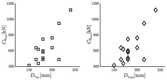
Figure 13.
Characteristics of the bearings solution selected from the SKF manual [37].

Table 7.
Search space definition of the NSGA-II algorithm.
6.3. Mechanical PTO
The selection of the PMSG and the gear stage, characterized by the gear reduction parameter , is determined by an integer value that identifies a specific component from a predefined database. Figure 14 illustrates the search space for the PTO system, showing the nominal power associated with each PTO. The nominal power is plotted for different gear reduction parameter, and represented as a function of the torque value and velocity on the gyropendulum side, denoted by and , respectively. The relationships between these parameters and the PTO values are and . Such parameters, related to the PTO system, establish the constraints for the optimization problem associated with the control parameter selection.
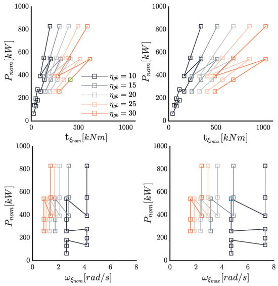
Figure 14.
Characteristics of the PTO solutions selected from the PMSG manual [38].
The proposed optimization is a mixed-integer optimization, as the parameters can be both real numbers and integer numbers. The main systems to be optimized are the floater, the gyropendulum, and the PTO system. Table 7 summarizes all the parameters for each subsystem, including their lower bound (LB) and upper bound (UB) values, determining, specifically, the algorithm search space. The parameters related to the floater are described in Section 6.1, while more details about the gyropendulum system and PTO system are presented in upcoming sections. These parameters are optimized to find the optimal device configuration that meets the desired objectives.
7. Cost Function Evaluation
Once the algorithm has been defined, and the search space has been characterized, the next step requires the statement of the optimization problem by delving into the details of the cost function setting, and the procedure for evaluating the two objectives in the NSGA-II algorithm. The techno-economic optimization of WEC devices, as presented in [22], can be summarized as outlined in Figure 15. The optimization cam involves three primary objectives: Total Capital Expenditure (CapEx), Annual Energy Productivity (AEP), and Total Operational Expenditure (OpEx). The total CapEx accounts for the dry cost of the WEC system, including the costs of its components, as well as the expenses associated with deployment. The AEP linked with the system performance represents the amount of energy generated by the WEC device over a year. Finally, OpEX considers the costs related to the operation and maintenance of the WEC device.
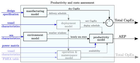
Figure 15.
Diagram of the possible techno-economic objective function involved in optimization of a WEC device.
However, this paper introduces the optimization of both the ISWEC and SWINGO devices with a primary focus on simultaneously reducing the dry cost, specifically the dry , while maximizing the AEP. These objectives are clearly emphasized in Figure 15 with bold lines. Based on this, the genetic algorithm will identify a set of solutions that provide different trade-offs between cost and annual energy productivity. This allows decision-makers to choose the most suitable solution based on their specific preferences and priorities.
7.1. Estimation of the Capital Expenditure
The SWINGO optimization includes a preliminary evaluation of the total cost of the device, in order to evaluate the investment behind a specific configuration and architecture. Three subsystems are considered into the cost evaluation: the floater, the mechanism unit, and the electronic circuits installed, associated with the PTO electronics. The overall cost of the device is defined by the sum of the cost of each subsystems, i.e.,
where , and are the costs associated with the hull, the gyropendulum unit, and the electronic components. In particular, all the costs related to each subsystem are characterized as follows:
- Unit system costs encompass all the expenses associated with carpentry and mechanical operations, as well as the costs related to the gearbox and electrical generators. These costs cover the various activities and components involved in the construction and assembly of the system.
- The costs associated with electronic components include various items such as supercapacitors, cables, electrical panels, batteries, inverters, and the Active Front-End (AFE) system.
- The costs associated with the steel hull includes the expenses of the steel hull construction, marine systems, e.g., fair-leads, chain-stoppers, bollards, and ship systems, e.g., bilge water pumps, stairs, gyropendulum installation platform.
Table 8 provides a breakdown of the costs associated with each subsystem. The cost for the hull-related components is determined in euros per kilogram EUR/kg, while the electronics costs are measured in euros per kilowatt EUR/kW. It is relevant to note that the cost of each subsystem is directly proportional to the structural mass of the hull and gyropendulum unit, as well as the total power installed in the system. By using a linear relationship, the overall cost of a subsystem can be calculated by multiplying the respective cost factor (EUR/kg or EUR/kW) with the corresponding mass or power values. This allows for a straightforward estimation of the cost contribution from each subsystem based on the system’s specific characteristics.

Table 8.
Costs associated with each device subsystem.
7.2. Annual Energy Productivity Evaluation
The second objective of the optimization is to maximize the AEP, as depicted in Figure 16. In the optimization process, each member of the population generated by the NSGA-II algorithm is represented by an individual with a specific chromosome. This chromosome contains genes that define the characteristics of the SWINGO system, including the floater, gyropendulum, and mechanical PTO system. The simulation is then conducted using the defined parameters to evaluate the AEP of each individual.
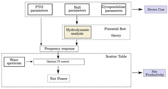
Figure 16.
Diagram of the simulation flow for the AEP computation.
Indeed, it is important to highlight that the optimization of the SWINGO and ISWEC systems is conducted in the North Sea and the Mediterranean Sea, taking into account the directional scatter characteristics (as discussed in Section 4). For each specific direction, a set of waves is selected, and their distribution over the North Sea scatter table is represented in Figure 17. The distribution of the selected waves over the Mediterranean Sea scatter tables can be appreciated within Figure 18 illustrates the selected wave, taking into account the distribution of wave energy and its occurrences. This wave has been chosen based on careful consideration of its characteristics and its relevance to the context of wave energy analysis.
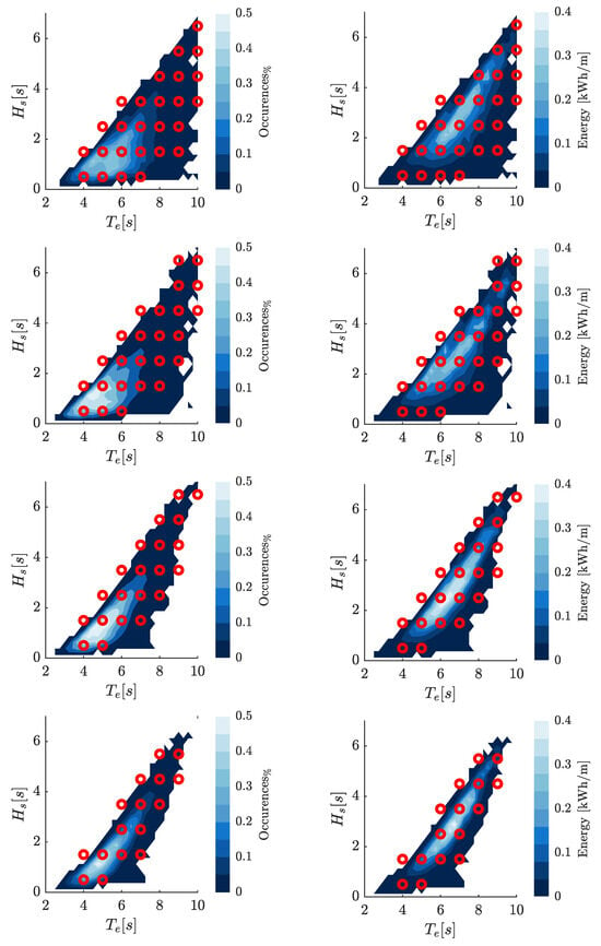
Figure 17.
Map of the selected simulation waves on the North Sea occurrences and energy tables for the four considered directions: , , , and .
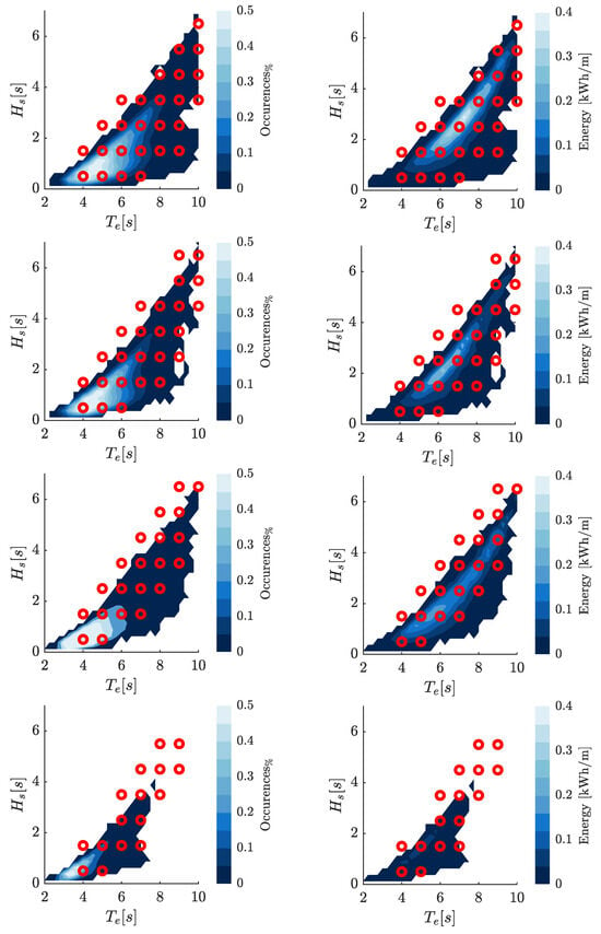
Figure 18.
Map of the selected simulation waves on the Pantelleria occurrences and energy tables for the four considered direction , , and .
The construction of the mechanical coupling matrix involves computing the reaction forces exerted by the gyropendulum system on the floater. These reaction forces are represented through damping and stiffness matrices, which capture the effects of these forces. The simulation matrices are built following the procedure widely presented in Section 2. To evaluate the system’s behavior, the simulation is performed in the FD, as outlined in Section 3. This approach enables the analysis of the system’s response to different wave conditions and the identification of optimal parameters. For each wave considered, a set of optimal control parameters is determined using constrained optimization techniques.
After evaluating the net power, the AEP associated with a specific installation site is computed. The AEP is defined as follows:
where represents the occurrence of a specific wave (in terms of percentage) in a year, of the j-th wave within the i-th direction set, and is the net power corresponding to that particular wave. Moreover, n is the number of waves considered in the simulation and 8760 is the number of hours in a year.
8. SWINGO Optimization
Based on the multi-objective optimization problem introduced in Equation (19), we aim to optimize the parameters of the SWINGO system, as detailed in Section 6. In particular, we focus on the results and the Pareto optimal solutions of the SWINGO system, comparing the set of optimal parameters for the two installation sites of interest. This comparison is performed alongside the ISWEC technology to highlight how the system characteristics and its optimality depend on the characteristics of the wave resource at a particular installation site.
8.1. Definition of Optimization Problem for the SWINGO System
For both SWINGO and ISWEC systems, the optimization process focuses on optimizing the AEP and the . These objectives are subject to constraints imposed by the SWINGO dynamical model , i.e., the map in (19). Instead, the set of inequalities defined by the map in (19) reduces to a set of bounds in terms of the optimization variable X, according to Table 7. Overall, the corresponding multi-objective optimization for SWINGO can be defined as
8.2. Pareto Optimal Solutions
This section focuses on comparing the results of the multi-objective optimization, specifically analyzing the optimization objectives and the trends observed in the techno-economic parameters. The first parameter considered is the Cost of Energy (CoE), defined from the capital expenditure and the annual productivity AEP,
where represents the number of years of the device’s operational life. In this specific application, the device’s operational life is set to 25 years. Moreover, the analysis in this section focuses on comparing the SWINGO technology and the ISWEC device, gaining insights into their respective performance and techno-economic characteristics. For this purpose, Figure 19 presents the cost and , normalized with respect to the maximum value obtained (referred as ) objectives for all the individuals, analyzed by the NSGA-II algorithm. It is worth noting that, in general, the AEP tends to be higher in Denmark compared to Pantelleria island. The observation that the AEP is generally higher in Denmark suggests that the wave conditions and resource availability in that location are more favorable for wave energy conversion compared to Pantelleria island. In particular, the analysis reveals that the ISWEC system achieve a minimum value of of about 0.4, while less than 0.2 is obtained for SWINGO. This indicates the target level of cost efficiency that the optimization process aims to achieve for each technology. Furthermore, when comparing the CoE between SWINGO and ISWEC in both installation sites, it becomes apparent that SWINGO consistently yields better results. This means that, for a given investment, the SWINGO technology provides higher AEP results compared to alternative combinations of technology and installation sites.
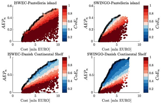
Figure 19.
Scatter diagram of the analyzed individuals by the NSGA-II, clustered according the device cost and AEP.
Indeed, Figure 20 provides an illustration of the Pareto frontiers derived from the data presented in Figure 19. The figure differentiates between the two installation sites, with blue lines representing Pantelleria island in the Mediterranean Sea and orange lines representing the installation site in Denmark. Additionally, the figure employs light colors for ISWEC and dark colors for SWINGO to distinguish between the two wave energy conversion technologies. By examining the Pareto frontiers, it is evident that there is a ranking in terms of performance between the two installation sites. In Denmark, superior performance can be achieved when compared to deployments in Pantelleria. This disparity can be attributed to the higher energy potential available at the Danish installation site. Furthermore, it is worth noting that SWINGO consistently outperforms ISWEC in both installation sites. The floater in the North Sea is more productive than at Pantelleria island, which explains why, generally, the AEP and consequently the CoE associated with both ISWEC and SWINGO technologies perform better in the North Sea than in the Mediterranean. In both locations, SWINGO, with a EUR 5 mln investment, outperforms ISWEC by approximately 20% in Pantelleria and 60% in the North Sea. This is due to SWINGO’s ability to harness small waves through the pendulum effect, making it more efficient in Pantelleria, while in the North Sea, its efficiency is enhanced by wave directionality.
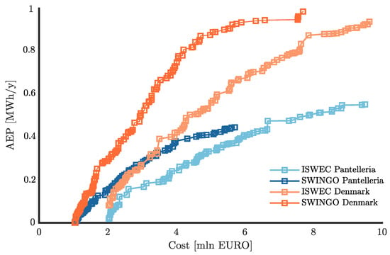
Figure 20.
Pareto frontier for both SWINGO and ISWEC technology considering both installation site.
8.3. Techno-Economic Evaluation
In the following analysis, the main parameters are evaluated and categorized into three distinct families based on the Pareto optimal solutions found in Figure 20. These families consist of dynamic parameters, techno-economic indexes, and parameters related to the technological solution. Each family provides insights into different aspects of the wave energy conversion systems. The main dynamic performance parameters considered are the stiffness factor and the inertia factor . The inertia factor is calculated as the ratio between the total inertia of the system and the centroid inertia associated with the three rigid bodies representing the gyropendulum system. While the dimensionless parameter denotes the ratio between the whole stiffness term of either the gyropendulum or gyroscope system and the one associated with the gyroscope of a reference ISWEC devices [20], denoted as . In particular, these are defined as follows:
Indeed, the parameters and provide insights on how to design a system capable of extracting energy from multiple directions. The higher the value of , the higher the term is. Similarly, the higher the value of , the higher the product of is. These parameters reflect the impact of the pendulum action into the system dynamic, hence the SWINGO ability to effectively harness energy from different wave directions. By optimizing these parameters, the system can maximize its energy extraction potential in various wave conditions and directions.
Additionally, Figure 21 shows the optimization results for , , and the periods and , being the resonant period associated with the hydrodynamic mode and the gyropendulum/gyroscope mode, respectively. It is important to highlight that the parameters and exhibit significantly higher values for the SWINGO system, installed in the North Sea, compared to the other combinations. This can be attributed to the highly multi-directional nature of the North Sea, which allows the optimizer to find a balance between the gyroscope operating mode for wave directions of and , and the pendulum operating mode for wave directions of and . On the other hand, for the Pantelleria site, although achieves a value of 4, the system prefers to primarily operate as a gyroscope, since the wave directions of propagation in that area are not as spread out during the year.
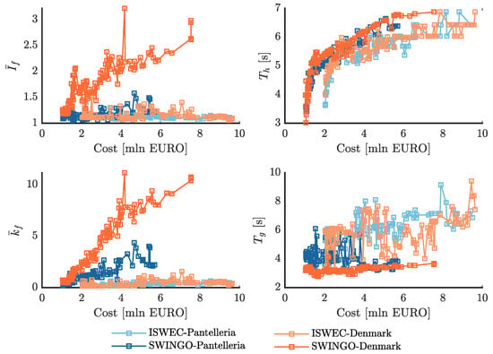
Figure 21.
Dynamic properties of the Pareto optimal solution for the SWINGO and ISWEC technology, considering both installation site.
Furthermore, it can be observed that as the cost of the device increases, the values of and also increase for the SWINGO system in the North Sea. This can be attributed to the fact that a larger floater is required to ensure the unit to fit into it, and a larger PTO, in terms of installed power, is needed to extract energy effectively. Recall that, in general, the higher the stiffness, the higher is the maximum value of the control action required, ultimately necessitating a bigger PTO system. ISWEC, on the other hand, exhibits values of and close to the lower admissible limits for both installation sites. This happens because ISWEC operates primarily as a gyroscope, where is always equal to 0 m. Additionally, due to its hydrodynamic characteristics, ISWEC may not efficiently harness energy from waves arriving from different directions. As a result, the optimizer tends to prioritize the gyroscope operating mode for ISWEC, which leads to lower values of and . These characteristics directly affect the resonant periods of the gyropendulum and gyroscope systems. The gyropendulum, being stiffer than a basic gyroscope, generally has a shorter resonant period. For SWINGO, the resonant period varies from 3 s to 5 s, depending on the stiffness and inertial properties. On the other hand, the gyroscope of ISWEC has a higher resonant period. However, for both devices, the hydrodynamic modes are designed to match the most energetic periods of the respective installation sites, ensuring optimal energy extraction.
8.4. Analysis on the Techno-Economic Indexes
The analysis presented herein focuses on parameters related to the device cost and the impact of the main subsystems on the total expenditure, as well as parameters related to the power capacity of the plant and the number of operating hours. These parameters include:
- Energy conversion efficiency: This parameter varies depending on the specific design and installation site of the device. It is determined by the size of the inverter selected for driving the power generator. The capacity factor (CF) is a dimensionless quantity that represents the ratio of the device’s AEP to its power rating , and is calculated as follows:The capacity factor is often expressed as a percentage () by multiplying the CF by 100.
- Working hours: This parameter varies depending on the specific design and installation site of the device. It represents the number of hours the device operates in a year.
- Hull cost ratio: This parameter varies depending on the specific design and installation site of the device. It represents the ratio of the cost associated with the hull construction to the total device cost.
- Unit cost ratio: this represents the ratio of the cost associated with the main unit (gyropendulum or gyroscope) to the total device cost.
Figure 22 demonstrates that the SWINGO technology installed in the North Sea exhibits a high value of working hours, reaching up to 70% of the total hours in a year. This indicates that the machine operates for a significant portion of the time. This is due to the fact that for low power capture, the pendulum mode of operation helps minimize losses, reducing baseload and bearing losses (as discussed in Section 3). Additionally, for small waves, the gross power generated by the system is greater than the system losses, making it more advantageous for the device to operate. On the other hand, for the ISWEC system, the operating hours are limited, since it operates for values of [rad/s], where the gross power is greater than the losses. In fact, the machine is switched off for small waves, because the flywheel rotation would require an amount of power greater than the power the device would produce. This means that the ISWEC system primarily operates during powerful waves, reducing the overall number of operating hours, compared to the SWINGO system. Indeed, the impact of the pendulum dynamics plays a significant role in determining the number of working hours. The higher the influence of the pendulum dynamics, the higher the number of working hours for the device. This is because the pendulum mode of operation can effectively capture energy even for low-power conditions, resulting in a longer operating duration.
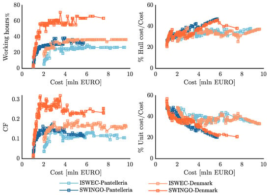
Figure 22.
Economic properties of the Pareto optimal solution for the SWINGO and ISWEC technology, considering both installation sites.
The CF reflects the system’s productivity and depends on the AEP and the power rating. In Denmark, the CF is higher for both SWINGO and ISWEC compared to the Mediterranean Sea. This indicates that the devices installed in Denmark are able to generate a higher proportion of their rated power output, resulting in a higher capacity factor. Regarding cost analysis, the hull cost is relatively consistent across different investment levels for all solutions. This is because the desired resonant period remains the same, and the dimensions of the hull are comparable. The hull cost accounts for approximately 20% to 40% of the total cost, with higher investments generally resulting in a higher hull cost. In the case of the unit cost, for the ISWEC system, it fluctuates around 20% across different investment levels. However, for the SWINGO system, the unit cost impact decreases as the investment increases. This may be due to certain parameters reaching saturation, while other components start to have a greater impact on the total cost.
8.5. Analysis on the Technological Parameters
In Figure 23, the trend of the main technological parameters is presented, specifically focusing on the hull length . It can be observed that the hull length increases linearly with the investment for both ISWEC and SWINGO devices. However, it is interesting to note that for investments greater than EUR 5 mln, the hull length saturates at a maximum value. This suggests that beyond a certain investment threshold, further increases in investment do not significantly affect the hull size and design. Regarding the flywheel inertia , for ISWEC, it follows a linear trend with respect to the investment. This indicates that, as the investment increases, the flywheel inertia is also increased proportionally. This linear relationship suggests that the design of the ISWEC system prioritizes the gyroscopic effect, utilizing the flywheel inertia to enhance the energy extraction efficiency. On the other hand, for SWINGO, the flywheel inertia saturates relatively quickly, starting from an investment of EUR 2 mln. This is due to the system’s attempt to balance the negative effects of high stiffness on the gyroscope motion. The use of a smaller flywheel inertia () allows for better control of the gyroscopic effect and mitigates the impact of high stiffness. In terms of total system mass, both ISWEC and SWINGO show a linear trend with respect to the investment. However, the slope of the trend is higher for SWINGO then ISWEC, indicating that the total mass of the SWINGO system is generally larger compared to ISWEC, implying that it may require a more robust and expensive mooring design to accommodate the larger loads associated with the higher total mass. Finally, in Figure 23, it is observed that the nominal power () of the generator installed in both ISWEC and SWINGO systems gradually increases with the cost of the device. This trend suggests that as the investment and device cost increase, there is a corresponding increase in the power capacity of the generator.
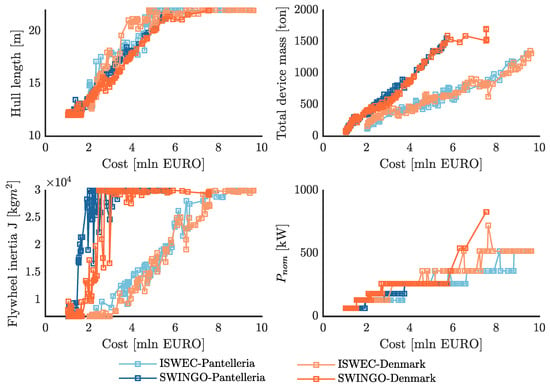
Figure 23.
Main design parameters of the Pareto optimal solution for the SWINGO and ISWEC technology, considering both installation sites.
8.6. Optimal Device Selection
The Pareto frontiers provide a set of optimal solutions, but the selection of the optimal design requires further analysis and decision-making. To focus on the region with the most advantageous values of CoE and select devices within the investment range of EUR 4 mln to EUR 5 mln, a number of devices are chosen. In particular, Table 9 presents the selected optimal designs for each combination of technology and installation site. For a fair comparison, the selected devices are characterized by a nominal power of 260 kW. In terms of the selected designs, it can be observed that SWINGO is more favorable in the North Sea due to its higher productivity and cost efficiency. The high level of energy potential in the North Sea makes SWINGO a more suitable choice, resulting in a higher AEP and lower CoE compared to ISWEC. On the other hand, in Pantelleria, the difference in productivity between SWINGO and ISWEC is less pronounced, indicating that the site conditions may not fully utilize the advantages of SWINGO’s technology. Table 10 also provides techno-economic parameters for the selected designs. Overall, the selection of optimal designs considers a trade-off between cost, performance, and site-specific characteristics. On this purpose, the results highlight the advantages of SWINGO in the North Sea, where its technology is well-suited to the high energy resource, resulting in superior performance and cost-efficiency.

Table 9.
Nominal data of the selected optimal ISWEC and SWINGO device.

Table 10.
Techno-economic parameters of the SWINGO and ISWEC devices selected from the Pareto optimal solution, considering both installation sites.
Figure 24 illustrates the floater dimension for the four selected devices. It is observed that the bigger the floater size, the higher is the value. In fact, considering the SWINGO labeled as 5859 and 5443, whose floater has a total length () smaller than 20 m, an values of 0.78 and 0.39 is exhibited, respectively. In comparison, their counterparts with larger floaters have values of 0.87 and 0.41. This indicates that, generally, increasing the floater size can lead to higher energy production.
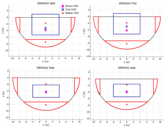
Figure 24.
Schematic floater representation of the SWINGO system selected from the Pareto frontiers of optimal devices designed for Pantelleria island and for the North Sea.
To further extend the analysis, the power scatter matrix associated to both ISWEC and SWINGO devices, displaying both the gross power and net power , for the four considered wave directions, are depicted in the Figures below. In particular, Figure 25 illustrates the gross and net power matrices of the SWINGO device 5443, designed for the Pantelleria island. These power matrices provide valuable information about the power production characteristics of the device, allowing for a comprehensive understanding of its performance under various wave conditions and directions.
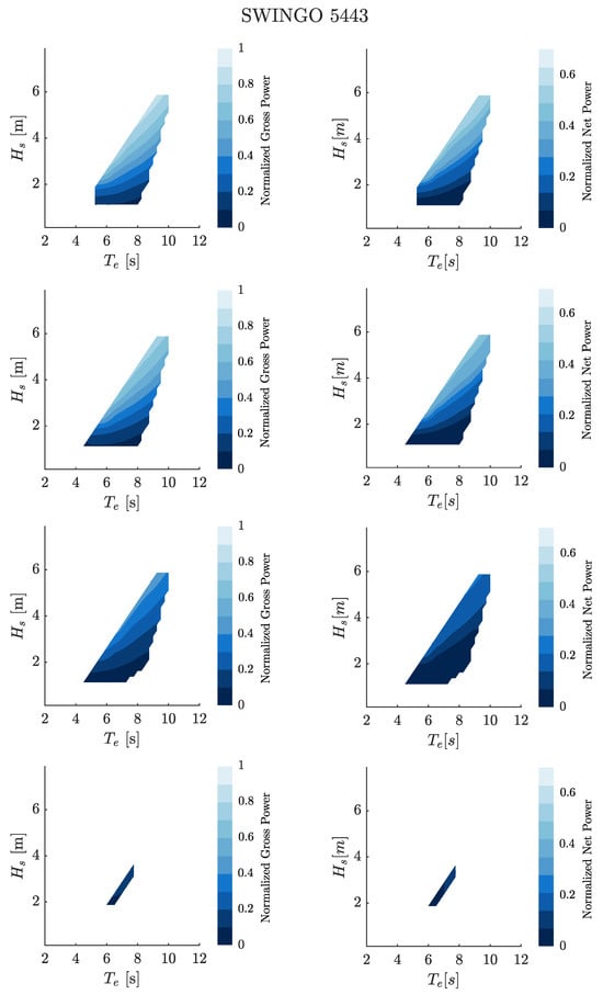
Figure 25.
Gross and net power metrics of the SWINGO 5443 for the four considered directions: , , , and .
Figure 26 illustrates the gross and net power matrices of the optimal ISWEC device 5359, designed for the North Sea.
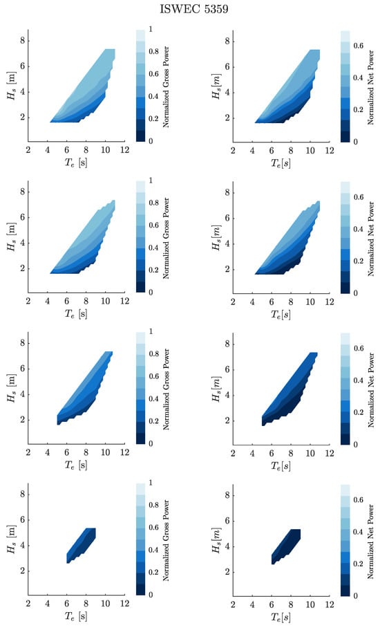
Figure 26.
Gross and net power metrics of the ISWEC 5359 for the four considered directions: , , , and .
Figure 27 illustrates the gross and net power matrices of the optimal ISWEC device 2288, designed for the Pantelleria island.
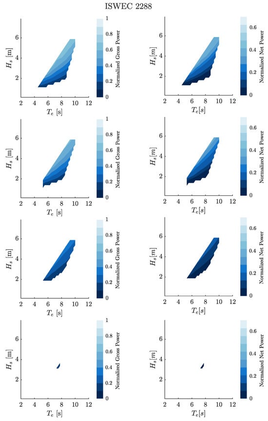
Figure 27.
Gross and net power metrics of the ISWEC 2288 for the four considered directions: , , , and .
Furthermore, Figure 28 illustrates the gross and net power matrices of the SWINGO device 5859, designed for the Danish site.
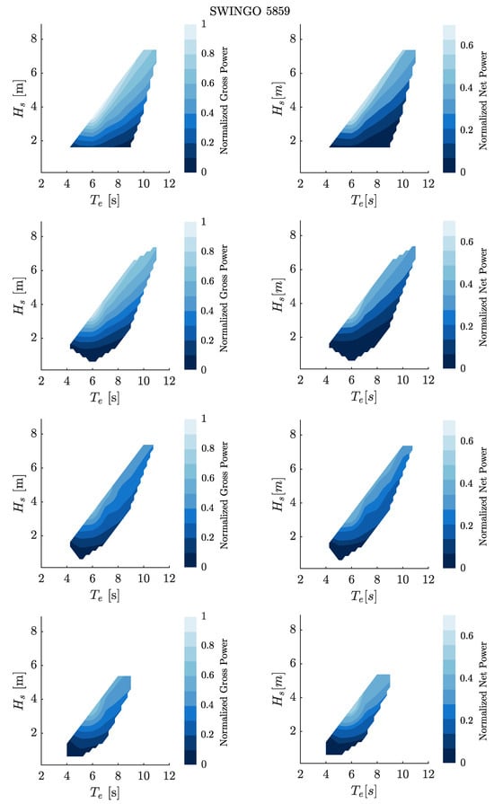
Figure 28.
Gross and net power metrics of the SWINGO 5859 for the four considered directions , , , and (from top to bottom).
9. Conclusions
The conclusions of this paper present the development and optimization of the SWINGO, a WEC system that integrates the novel gyropendulum technology. The methodology introduced for optimizing the SWINGO device involves a multi-modes simulation model to mimic the complex interaction between the floater and gyropendulum. Moreover, the SWINGO’s ability to work as a multi-directional WEC is a key feature, allowing it to effectively manage wave energy from multiple directions, has been manage considering, in the simulation model the relative arrival directions of the waves with respect to the floater orientation.
Moreover, SWINGO’s design incorporates several subsystems, including the floater, gyropendulum, and PTO. Through the application of the NSGA-II multi-objective optimization algorithm, we identified a set of optimal design parameters that enhance system performance while balancing conflicting objectives such as maximizing energy absorption and minimizing costs, thus ensuring economic feasibility.
A comparative analysis with the ISWEC benchmark demonstrated the SWINGO system’s superior performance, especially in multi-directional wave environments. SWINGO’s design benefits from its multi-axial coupling and advanced gyropendulum technology, which allows it to maintain higher performance than ISWEC, which relies on a single-axis gyroscope. While the SWINGO system exhibits notable advantages, especially in multi-directional wave sites where its CoE is significantly lower compared to ISWEC, which ability to extract power on wave direction different that the floater orientation axis is almost null, as demonstrated by the limited value of elasticity, that the ISWEC can achieve because of the gyroscope architecture. These aspects highlight the importance of simulating the SWINGO device under conditions as close to reality as possible, particularly to understand the impact of wave directionality on system performance and characteristics. In particular, accurately modeling the multi-directional nature of real-world wave environments allows for a more precise evaluation of how the device behaves under various conditions, ultimately leading to better performance optimization and more reliable operational predictions. Although advanced resource information has been integrated, it is important to emphasize that the system design is based on the well-established PI control method. While PI control provides a solid starting solution, incorporating an optimal control algorithm into the optimization process could significantly enhance the system’s performance. By considering a control-informed optimization process from the early design stages, the WEC system could be better equipped to handle optimal control strategies, particularly influencing the selection of the PTO for achieving maximum torque and velocity. This presents a promising direction for future advancements in this work.
Author Contributions
Conceptualization, F.C., S.A.S. and G.G.; Methodology, F.C.; Software, F.C., S.A.S. and M.B.; Formal analysis, F.C., S.A.S. and G.G; Investigation, F.C., V.D.C., M.B. and N.F.; Writing—original draft, F.C., V.D.C. and N.F.; Writing—review & editing, G.G and M.B.; Supervision, S.A.S., N.F. and E.G.; Project administration, E.G.; Funding acquisition, E.G. All authors have read and agreed to the published version of the manuscript.
Funding
This research received no external funding.
Data Availability Statement
Data available upon request.
Conflicts of Interest
The authors declare no conflicts of interest.
Nomenclature
| Annual Energy Productivity | |
| Active Front-End | |
| Bounded Exponential | |
| Ballast Filling Ratio | |
| Capital Expenditure | |
| Capacity Factor | |
| Center-of-Gravity | |
| Cost-of-Energy | |
| Degree-of-Freedom | |
| Evolutionary Algorithm | |
| Exhaustive Search | |
| Frequency-Domain | |
| Genetic Algorithm | |
| High Performance Computing | |
| inertial Reaction Mass Wave Energy Converter | |
| Inertial Reaction Mass | |
| Inertial Sea Wave Energy Converter | |
| Joint North Sea Wave Observation Project | |
| Lower Bound | |
| - | Non-dominated Sorting Genetic Algorithm II |
| Operational Expenditure | |
| Oscillating Water Columns | |
| Optimal Control Problem | |
| Point Absorber | |
| Pendulum Wave Energy Converter | |
| Proportional Integral | |
| Power Mutation | |
| Permanent Magnet Synchronous Generator | |
| Power Spectral Density | |
| Power Take-Off | |
| Swinging Omnidirectional Wave Energy Converter | |
| Time-Domain | |
| Upper Bound | |
| Wave Energy Converter |
References
- Wang, F.; Harindintwali, J.D.; Yuan, Z.; Wang, M.; Wang, F.; Li, S.; Yin, Z.; Huang, L.; Fu, Y.; Li, L.; et al. Technologies and perspectives for achieving carbon neutrality. Innovation 2021, 2, 100180. [Google Scholar] [CrossRef] [PubMed]
- IRENA. Renewable Energy Statistics 2019; Technical Report; The International Renewable Energy Agency: Abu Dhabi, United Arab Emirates, 2019. [Google Scholar]
- Gunn, K.; Stock-Williams, C. Quantifying the global wave power resource. Renew. Energy 2012, 44, 296–304. [Google Scholar] [CrossRef]
- Terrero González, A.; Dunning, P.; Howard, I.; McKee, K.; Wiercigroch, M. Is wave energy untapped potential? Int. J. Mech. Sci. 2021, 205, 106544. [Google Scholar] [CrossRef]
- Avila, D.; Marichal, G.N.; Quiza, R.; San Luis, F. Prediction of Wave Energy Transformation Capability in Isolated Islands by Using the Monte Carlo Method. J. Mar. Sci. Eng. 2021, 9, 980. [Google Scholar] [CrossRef]
- Guo, B.; Wang, T.; Jin, S.; Duan, S.; Yang, K.; Zhao, Y. A Review of Point Absorber Wave Energy Converters. J. Mar. Sci. Eng. 2022, 10, 1534. [Google Scholar] [CrossRef]
- Song, R.; Zhang, M.; Qian, X.; Wang, X.; Dai, Y.; Chen, J. A Floating Ocean Energy Conversion Device and Numerical Study on Buoy Shape and Performance. J. Mar. Sci. Eng. 2016, 4, 35. [Google Scholar] [CrossRef]
- Henry, A.; Doherty, K.; Cameron, L.; Doherty, R.; Whittaker, T. Advances in the Design of the Oyster Wave Energy Converter. In Proceedings of the Marine Renewable and Offshore Wind Energy, RINA, London, UK, 21–23 April 2010; pp. 119–128. [Google Scholar] [CrossRef]
- Mahnamfar, F.; Altunkaynak, A. Comparison of numerical and experimental analyses for optimizing the geometry of OWC systems. Ocean. Eng. 2017, 130, 10–24. [Google Scholar] [CrossRef]
- Fenu, B.; Bonfanti, M.; Bardazzi, A.; Pilloton, C.; Lucarelli, A.; Mattiazzo, G. Experimental investigation of a Multi-OWC wind turbine floating platform. Ocean Eng. 2023, 281, 114619. [Google Scholar] [CrossRef]
- Clemente, D.; Rosa-Santos, P.; Taveira-Pinto, F.; Martins, P. Influence of platform design and power take-off characteristics on the performance of the E-Motions wave energy converter. Energy Convers. Manag. 2021, 244, 114481. [Google Scholar] [CrossRef]
- Guo, B.; Ringwood, J.V. Non-Linear Modeling of a Vibro-Impact Wave Energy Converter. IEEE Trans. Sustain. Energy 2021, 12, 492–500. [Google Scholar] [CrossRef]
- Carapellese, F.; Pasta, E.; Paduano, B.; Faedo, N.; Mattiazzo, G. Intuitive LTI energy-maximising control for multi-degree of freedom wave energy converters: The PeWEC case. Ocean. Eng. 2022, 256, 111444. [Google Scholar] [CrossRef]
- Clement, A.; Babarit, A.; Gilloteaux, J.C. The Searev Wave Energy Converter. In Proceedings of the European Wave and Tidal Energy Conference, Glasgow, UK, 29 August–3 September 2005. [Google Scholar]
- Cordonnier, J.; Gorintin, F.; De Cagny, A.; Clément, A.; Babarit, A. SEAREV: Case study of the development of a wave energy converter. Renew. Energy 2015, 80, 40–52. [Google Scholar] [CrossRef]
- Durand, M.; Babarit, A.; Petinotti, B.; Clement, A. Experimental Validation of the Performances of the SEAREV Wave Energy Converter with Real-Time Latching Control. In Proceedings of the 7th European Wave and Tidal Energy Conference, Porto, Portugal, 11–13 September 2007. [Google Scholar]
- Crowley, S.; Porter, R.; Taunton, D.; Wilson, P. Modelling of the WITT wave energy converter. Renew. Energy 2018, 115, 159–174. [Google Scholar] [CrossRef]
- Wello, O. The Wello Penguin Wave Energy Converter. Available online: https://holvienergy.com/index.html (accessed on 15 October 2024).
- Boren, B.C.; Lomonaco, P.; Batten, B.A.; Paasch, R.K. Design, Development, and Testing of a Scaled Vertical Axis Pendulum Wave Energy Converter. IEEE Trans. Sustain. Energy 2017, 8, 155–163. [Google Scholar] [CrossRef]
- Bonfanti, M.; Sirigu, S.A. Spectral-domain modelling of a non-linear wave energy converter: Analytical derivation and computational experiments. Mech. Syst. Signal Process. 2023, 198, 110398. [Google Scholar] [CrossRef]
- Carapellese, F.; Pasta, E.; Sirigu, A.S.; Faedo, N. SWINGO: Conceptualization, modelling and control of a swinging omni-directional Wave Energy Converter. Mech. Syst. Signal Process. 2023, 197, 110356. [Google Scholar] [CrossRef]
- Guo, B.; Ringwood, J.V. Geometric optimisation of wave energy conversion devices: A survey. Appl. Energy 2021, 297, 117100. [Google Scholar] [CrossRef]
- Garcia-Rosa, P.; Bacelli, G.; Ringwood, J. Control-Informed Geometric Optimization of Wave Energy Converters: The Impact of Device Motion and Force Constraints. Energies 2015, 8, 13672–13687. [Google Scholar] [CrossRef]
- Bouali, B.; Larbi, S. Sequential optimization and performance prediction of an oscillating water column wave energy converter. Ocean. Eng. 2017, 131, 162–173. [Google Scholar] [CrossRef]
- Lorenzini, G.; Lara, M.; Rocha, L.; Gomes, M.; Santos, E.; Isoldi, L. Constructal design applied to the study of the geometry and submergence of an oscillating water column. Int. J. Heat Technol. 2015, 33, 31–38. [Google Scholar] [CrossRef][Green Version]
- Deb, K. Multi-Objective Optimization Using Evolutionary Algorithms; Wiley: Hoboken, NJ, USA, 2001. [Google Scholar]
- Sirigu, S.A.; Foglietta, L.; Giorgi, G.; Bonfanti, M.; Cervelli, G.; Bracco, G.; Mattiazzo, G. Techno-Economic Optimisation for a Wave Energy Converter via Genetic Algorithm. J. Mar. Sci. Eng. 2020, 8, 482. [Google Scholar] [CrossRef]
- Wang, W.; Zhao, C.; Peng, W.; Ding, W.; Chen, M.; Li, Y.; Johanning, L. Nonlinear mooring system for a ‘Sharp-Eagle’ wave energy converter. Ocean. Eng. 2022, 260, 111970. [Google Scholar] [CrossRef]
- Penalba, M.; Ringwood, J.V. A high-fidelity wave-to-wire model for wave energy converters. Renew. Energy 2019, 134, 367–378. [Google Scholar] [CrossRef]
- Paduano, B.; Giorgi, G.; Gomes, R.P.F.; Pasta, E.; Henriques, J.C.C.; Gato, L.M.C.; Mattiazzo, G. Experimental Validation and Comparison of Numerical Models for the Mooring System of a Floating Wave Energy Converter. J. Mar. Sci. Eng. 2020, 8. [Google Scholar] [CrossRef]
- Falnes, J. Ocean Waves and Oscillating Systems; Cambridge University Press: Cambridge, MA, USA, 2002. [Google Scholar] [CrossRef]
- Merigaud, A.; Ringwood, J.V. Free-Surface Time-Series Generation for Wave Energy Applications. IEEE J. Ocean. Eng. 2018, 43, 19–35. [Google Scholar] [CrossRef]
- Cummins, W.E. The impulse response function and ship motions. In Proceedings of the Symposium on Ship Theory at the Institut flir Schiffbau der Universitit Hamburg, Hamburg, Germany, 25–27 January 1962. [Google Scholar]
- Carapellese, F.; Faedo, N. Mechanical interactions modeling of inertial wave energy converters. Int. J. Mech. Sci. 2024, 284, 109731. [Google Scholar] [CrossRef]
- Lutes, L.D.; Sarkani, S. Random Vibrations; Elsevier: Amsterdam, The Netherlands, 2004. [Google Scholar] [CrossRef]
- Sirigu, A.S.; Gallizio, F.; Giorgi, G.; Bonfanti, M.; Bracco, G.; Mattiazzo, G. Numerical and Experimental Identification of the Aerodynamic Power Losses of the ISWEC. J. Mar. Sci. Eng. 2020, 8, 49. [Google Scholar] [CrossRef]
- SKF. The SKF Model for Calculating the Frictional Moment. Available online: https://cdn.skfmediahub.skf.com/api/public/0901d1968065e9e7 (accessed on 15 October 2024).
- SIEMENS. SIMOTICS T-1FW3 Complete Torque Motors for SINAMICS S120. 2023. Available online: https://mall.industry.siemens.com/mall/en/ww/catalog/products/10034485 (accessed on 15 October 2024).
- Mattiazzo, G. State of the Art and Perspectives of Wave Energy in the Mediterranean Sea: Backstage of ISWEC. Front. Energy Res. 2019, 7, 114. [Google Scholar] [CrossRef]
- Beels, C.; Henriques, J.C.; De Rouck, J.; Pontes, M.T.; De Backer, G.; Verhaeghe, H. Wave energy resource in the North Sea Introduction. In Proceedings of the 7th European Wave and Tidal Energy Conference (EWTEC 2007), Porto, Portugal, 11–13 September 2007. [Google Scholar] [CrossRef]
- Hersbach, H.; Bell, B.; Berrisford, P.; Hirahara, S. The ERA5 global reanalysis. Q. J. R. Meteorol. Soc. 2020, 146, 1999–2049. [Google Scholar] [CrossRef]
- Beels, C. Optimization of the Lay-Out of a Farm of Wave Energy Converters in the North Sea Analysis of Wave Power Resources, Wake Effects, Production and Cost. Ph.D. Thesis, Ghent University, Ghent, Belgium, 2010. [Google Scholar]
- Jalota, H.; Thakur, M. Genetic Algorithm Designed for Solving Linear or Nonlinear Mixed-Integer Constrained Optimization Problems. In International Proceedings on Advances in Soft Computing, Intelligent Systems and Applications: ASISA 2016; Springer: Singapore, 2018; pp. 277–290. [Google Scholar] [CrossRef]
- Thakur, M.; Meghwani, S.S.; Jalota, H. A modified real coded genetic algorithm for constrained optimization. Appl. Math. Comput. 2014, 235, 292–317. [Google Scholar] [CrossRef]
- Shopova, E.G.; Vaklieva-Bancheva, N.G. BASIC A genetic algorithm for engineering problems solution. Comput. Chem. Eng. 2006, 30, 1293–1309. [Google Scholar] [CrossRef]
Disclaimer/Publisher’s Note: The statements, opinions and data contained in all publications are solely those of the individual author(s) and contributor(s) and not of MDPI and/or the editor(s). MDPI and/or the editor(s) disclaim responsibility for any injury to people or property resulting from any ideas, methods, instructions or products referred to in the content. |
© 2024 by the authors. Licensee MDPI, Basel, Switzerland. This article is an open access article distributed under the terms and conditions of the Creative Commons Attribution (CC BY) license (https://creativecommons.org/licenses/by/4.0/).