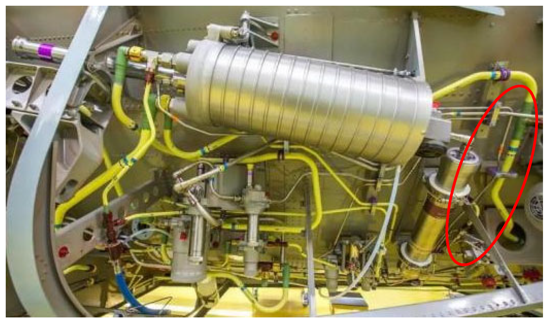
The aircraft hydraulic actuator is a key component of the aircraft hydraulic system, responsible for converting hydraulic energy into mechanical energy to perform various flight control and operation tasks. It usually consists of a hydraulic cylinder, piston, piston rod, and associated seals. The hydraulic actuator pushes the piston in motion through the pressurized hydraulic oil provided by the hydraulic pump, thus creating a linear or rotational motion. This movement is used to control the aircraft’s elevator, ailerons, and rudder, and the expansion of the landing gear. Hydraulic actuators have high efficiency and reliable and responsive characteristics, and can work with a high load and under high-pressure conditions. The design’s durability and safety must be considered to ensure it has stable energy under various flight conditions. Regular maintenance and inspection are essential to ensure the normal operation of the hydraulic actuators and to extend their service life. The red circle in
Figure 1 denotes the aircraft hydraulic system.
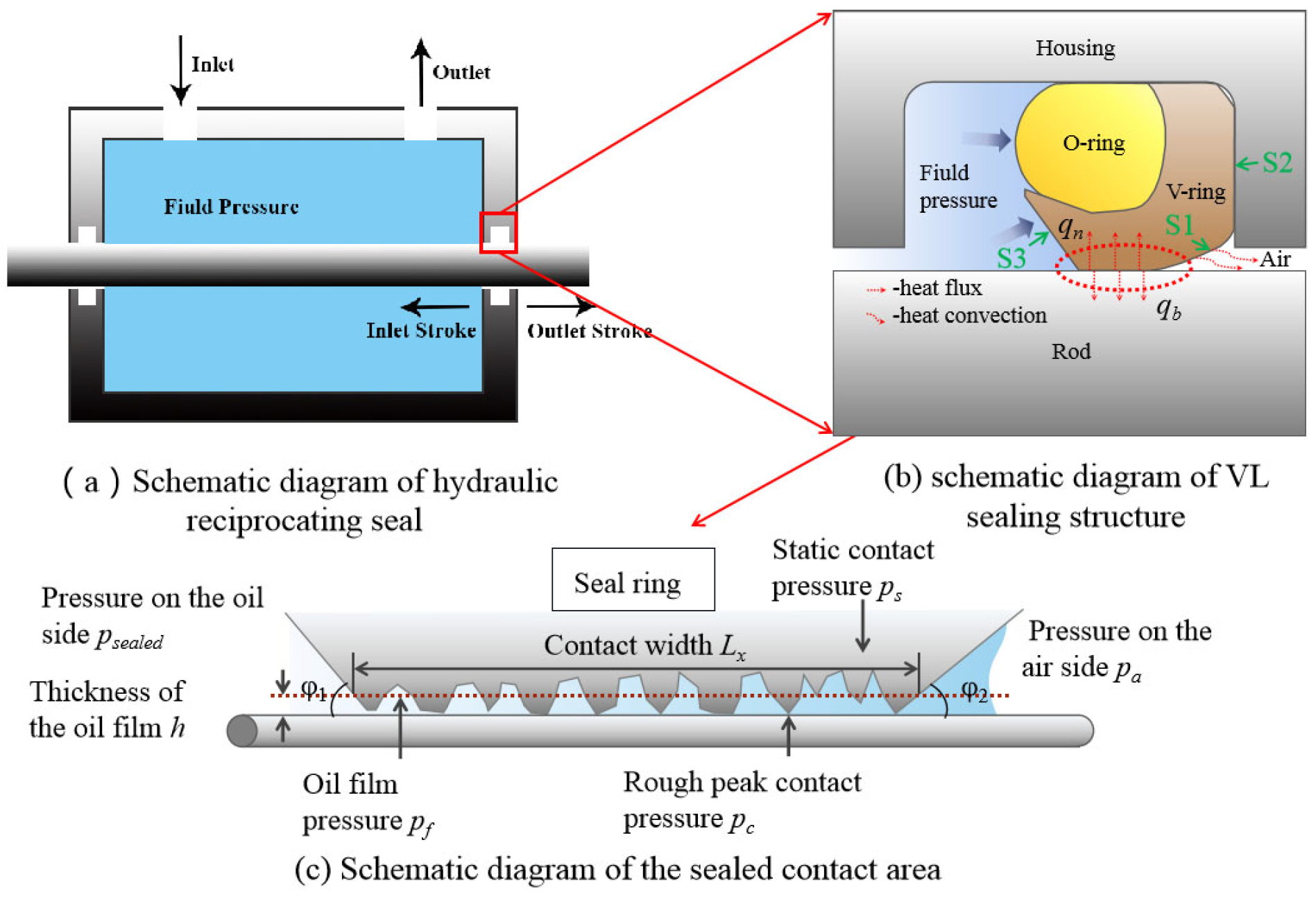
During the working process of the hydraulic reciprocating seal device (
Figure 2a), when the piston rod moves outward (i.e., the outstroke), the piston rod moves to the air side, and a small amount of hydraulic oil will be brought out by the piston rod during this process; when the piston rod moves inward (i.e., the instroke), the piston rod moves into the inside of the hydraulic cylinder and will return a small amount of hydraulic oil from the air side to the inside of the hydraulic cylinder. After a stroke cycle is completed, the amount brought out during the outstroke minus the amount brought in during the instroke is the actual leakage amount of a working cycle of the hydraulic cylinder.
Figure 2b shows the schematic diagram of the VL model sealing structure model. According to the research of relevant scholars, the hydraulic reciprocating sealing structure is always in a mixed lubrication state during work [
1,
2]. Therefore, it is indicated that there is both an oil film and contact between the sealing material and the piston rod in the sealing area (
Figure 2c). In order to accurately obtain the friction characteristics and leakage rate of the sealing structure, it is necessary to study and discuss the characteristics of the lubricating oil film thickness and the oil film pressure.
2.1. Hypothesis of the Thermal Elastohydrodynamic Model for Hydraulic Reciprocating Seals
The calculation of the hydraulic reciprocating seal oil film is solved using the most basic equations of fluid lubrication theory, namely the Reynolds equation derived from the motion equation and the continuity equation. Before establishing the model, the following assumptions need to be made:
- (1)
There is no sliding at the interface of the fluid.
- (2)
The effect of volume forces (such as gravity) is ignored.
- (3)
The pressure change in the fluid in the direction along the thickness of the lubricating film is ignored.
The above assumptions are for general fluid problems. To simplify the problem, the following assumptions are introduced:
- (1)
The lubricating fluid is a Newtonian fluid.
- (2)
The flow of the oil film is laminar, without an eddy current and turbulence.
- (3)
The inertia force of the fluid is ignored.
- (4)
The viscosity value of the fluid remains constant in the direction along the thickness of the lubricating film.
Based on all the above assumptions, the Reynolds equation is derived from the Navier–Stokes equation and the continuity equation using the infinitesimal element analysis method. The specific steps are as follows: First, the velocity distribution of the fluid along the thickness direction of the film is obtained based on the force balance condition of the fluid’s infinitesimal elements. Secondly, the fluid flow rate is obtained by integrating the fluid along the thickness direction of the lubricating film. Finally, the Reynolds equation is derived based on the continuous condition of the flow rate. In order to minimize the error under the hypothesis conditions, the HIDALISS type 32 hydraulic oil produced in China was selected as the experimental hydraulic oil, with a viscosity of 32 mm2/s.
2.2. Nonlinear Elastic Mechanics Analysis
When using the elastic hydrodynamic lubrication method, due to the extremely thin film thickness, the mixed lubrication contact pressure distribution in the sealing contact area under static conditions is almost the same as the dry contact pressure distribution. Therefore, the finite element method can be used to determine the dry contact pressure in the sealing area. The studied VL seal structure consists of an O-ring and a V-ring, forming a combined seal structure. Therefore, during the calculation process, it can be converted into a two-dimensional axisymmetric model to reduce the amount of calculation required. In the VL seal structure, the elastic modulus of rubber and PTFE materials is much smaller than that of steel, so it can be assumed that the piston rod and the housing have no deformation process. The material of the O-ring is mainly NBR material, and its stress–strain behavior can be described by the Mooney–Rivlin model. The model parameters in this paper are taken from the literature [
13]: C
10 = 0.202, C
01 = 6.858. The Mooney–Rivlin model describes the nonlinear behavior of materials on the basis of the strain energy density function; this is a widely recognized model with high analytical accuracy. The strain energy function of the M-R native model of the rubber material is as follows:
where I
1 and I
2 are the first and second invariants of the strain tensor, respectively, while C
10 and C
01 are the M-R constant, reflecting the stress and strain properties of the material; d
0 and J are the parameters reflecting the elastic deformation degree of the material, and W is the strain energy density.
The material of the V-ring is mainly polytetrafluoroethylene (PTFE), and its mechanical properties can be described using the isotropic yield model of the Mises yield surface theory. In this paper, the pre-tightening force is applied to the seal structure to determine the compression of the seal structure, and the fluid infiltration load is used to determine the oil side’s pressure boundary conditions. The dry contact pressure distribution under different working conditions is calculated using the finite element analysis method.
As shown in
Figure 2c, the VL sealing structure is affected by the combined effect of three forces: the preload force formed by the seal installation force, the piston rod, the support force of the sealing material, and the fluid force of the sealing structure. The three forces can be viewed as equivalent to three contact pressure: static contact pressure
ps, rough peak contact pressure
pc and oil film pressure p
f, respectively. Among them, the rough peak contact pressure
pc and the oil film pressure
pf act on the surface of the sealing lip and move vertically upward, while the static contact pressure
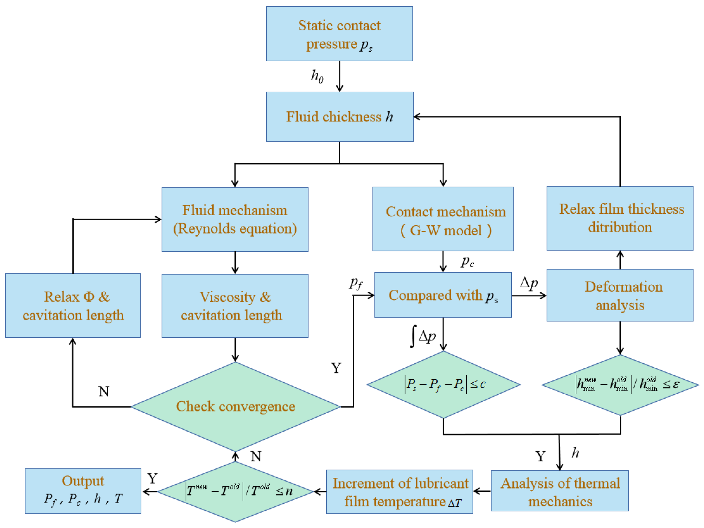
ps of the seal ring acts on the sealing lip in a direction perpendicular to the downward direction. Under the combined action of these three pressures, the seal lip of the seal ring will deform, thereby changing the oil film thickness
h. The change in the oil film thickness
h will, in turn, change the oil film pressure
pf and the rough peak contact pressure
pc. Eventually, when the three pressures in the seal ring area reach a balance, the oil film thickness
h will no longer change, the entire numerical solution process will converge, and the final oil film pressure
pf, rough peak contact pressure
pc, oil film thickness
h, friction force
F, and leakage q can be obtained.
2.3. Viscous Fluid Dynamics Analysis
At present, when the traditional elastic fluid dynamic lubrication model uses the influence coefficient matrix method to calculate the microelastic deformation of the sealing element, the extraction of the influence coefficient matrix requires a lot of simulation calculations using the finite element software. In order to facilitate the convergence of the flow–solid coupling iterative calculations and reduce the computation time as much as possible, the contact area of the seal ring and the plunger is often established using a local grid, which greatly increases the time needed to extract the influence coefficient matrix using finite element software. The fluid dynamic lubrication method is calculated, or the measured static contact pressure is assumed to be approximately equal to the fluid pressure. Using the Renault equation, the thickness of the oil membrane can be determined, and then the sealing performance parameters of the friction force and the roughness and the thickness of the oil membrane can be obtained. Therefore, we first obtain an approximate initial film thickness distribution using the hydrodynamic inverse solution method, which is then corrected using the elastic hydrodynamic lubrication method.
Firstly, according to the literature [
14], the Reynolds equation can be simplified into the following one-dimensional steady-state form:
In the formula,
h is the average oil film thickness in the sealing area,
μ is the fluid dynamic viscosity,
pf is the fluid pressure in the sealing area, and
u is the reciprocating speed of the piston rod. Integrating the above formula leads to the following equation:
where
h0 is the oil film thickness at the maximum pressure,
dp/
dx = 0. Differentiating both sides of Formula (3) leads to the following:
At the inflection point a of the fluid pressure,
d2p/
dx2 = 0; therefore, the oil film thickness at this point can be expressed as follows:
Substituting Equation (5) into Equation (3) provides the following:
The following pressure gradient
G and oil film thickness
H′ can be defined as follows:
Equations (7) and (8) can be substituted into Equation (2); after simplification, a cubic equation for
H can be obtained:
By calculating the fluid pressure distribution function
pf(x) and solving Equations (6), (7) and (9), the average oil film thickness distribution in the sealing area is obtained. The above content shows the process of calculating the film thickness using the hydrodynamic inverse solution method. Next, the elastic hydrodynamic lubrication method is used to correct the thickness of the film. According to the research [
15] of Salant et al., using the dimensionless Reynolds equation considering cavitation and surface roughness, the pressure distribution under a fixed film thickness is obtained. Since the fluid in the sealing area cavitates when the fluid pressure is less than the cavitation pressure
pcav, this paper uses the Jakobsson–Floberg–Olsson (JFO) cavitation theory for its description [
16]. “When the piston or piston rod is rapidly moving fast in the cylinder, there may be a local low-pressure area near the air side of the sealing lip. If the pressure is lower than the evaporative pressure of the hydraulic oil, the hydraulic oil may evaporate to form bubbles, creating a cavitation effect”. According to the JFO cavitation theory, the sealed lubrication region can be divided into a fully fluid region and a gas–liquid coexistence region, and mass conservation is observed in the fully fluid region, the cavitation region, and the interface between the two. By assuming the previous conditions, the sealing structure can be simplified into a one-dimensional axisymmetric model to reduce the calculation time. The Reynolds equation considering fluid cavitation effects is obtained from Elrod [
17], Payvar [
18], and Xiong [
19]:
h is the average oil film thickness,
ht is the truncated true film thickness.
pa is the atmospheric pressure, and
pcav is the cavitation pressure; the pressure flow factors in the x direction and the correction factor of the velocity component cause the medium to flow.
u is the rod speed,
F is the cavitation factor, and
Φ is the average density function, obtained from Reference [
4]. The boundary conditions are as follows:
In Equation (10), μ is obtained from the viscosity–temperature equation [
20,
21]:
In Equation (11),
μ0 is the viscosity of fluid at normal pressure, and α is the viscosity–pressure coefficient.
T0 is the reference temperature,
T is the film temperature of the model fluid, and
β is the viscosity–temperature correction coefficient. The local thickness of the oil film is as follows:
When two rough surfaces come into contact, the oil film is truncated so that the local oil film thickness
hT at that location is equal to 0; when solving the contact deformation problem of two rough surfaces, this is generally equivalent to a rough surface and a smooth surface coming into contact, and the comprehensive rough peak deviation from the centerline amplitude
δ(x, y) of the equivalent rough surface is as follows:
Using probability and statistics methods, assuming that the rough peak of the rough surface follows the probability density function distribution of f(δ), the average oil film thickness can be written as follows:
Assuming that the surface rough peak follows a Gaussian function distribution, Equation (17) can be calculated using the following formula:
2.4. Microscopic Contact Mechanics Analysis
Hydraulic reciprocating seals work in such a way that there is a sealing surface in the contact area between the seal ring and the piston rod, which includes not only the physical contact between the two, but also the contact relationship between the hydraulic oil (
Figure 2c). Therefore, this paper uses the G-W contact model to describe the interaction between the roughnesses of the sealing friction pair surfaces [
22]. This model assumes that each vertex of the roughness is a sphere with the same radius, each roughness is calculated using Hertz contact theory, and the roughnesses are independent of each other and do not affect each other. The dynamic contact pressure
pc is calculated as follows:
In Formula (19),
Fa is the total contact load,
An is the density of rough peaks on the nominal contact area,
ρ is the roughness density,
R is the roughness radius,
is the equivalent elastic modulus of the two surfaces, calculated by Formula (19), and
h is the probability density function of the peak.
In Formula (20),
is the equivalent elastic modulus;
E1,
E2,
and
are the elastic modulus and Poisson’s ratio of the two contact surface materials, respectively. Since the elastic modulus
E1 of the rigid material plunger is much larger than the elastic modulus
E2 of the flexible material seal ring, the flexible material elastic factor can be ignored, and the equivalent elastic modulus is simplified as follows:
In Formula (22), σs represents the standard deviation of the peak.
2.5. Microscopic Deformation Analysis
According to
Section 2.2, the oil film thickness generated by the hydrodynamic pressure effect is much smaller than the radial deformation in the sealing element during installation and pressurization.
During a reciprocating motion, the compression and rebound contact force of the sealing element are approximately equal to the static contact force. Therefore, the micro-elastic deformation
Hdef of the sealing element in the sealing area during a reciprocating motion is caused by the pressure difference between the supporting force, composed of the fluid pressure pf and the roughness contact pressure
pc, and the rebound contact pressure
ps, which causes the radial deformation of the sealing material and the piston rod:
The oil film thickness is at the micron scale, and the small deformation linear superposition theory can be used. The change in the oil film thickness at any point in the sealing area is equal to the sum of the displacements generated by all nodes in the contact area at that point. The elastic deformation generated by the pressure Δ
pj at node
j in the sealing area at
xi is as follows:
If
kij represents the deformation amount of node
i under unit load at node
j, then the oil film thickness at any point in the sealing area can be expressed as follows:
2.6. Thermodynamic Analysis
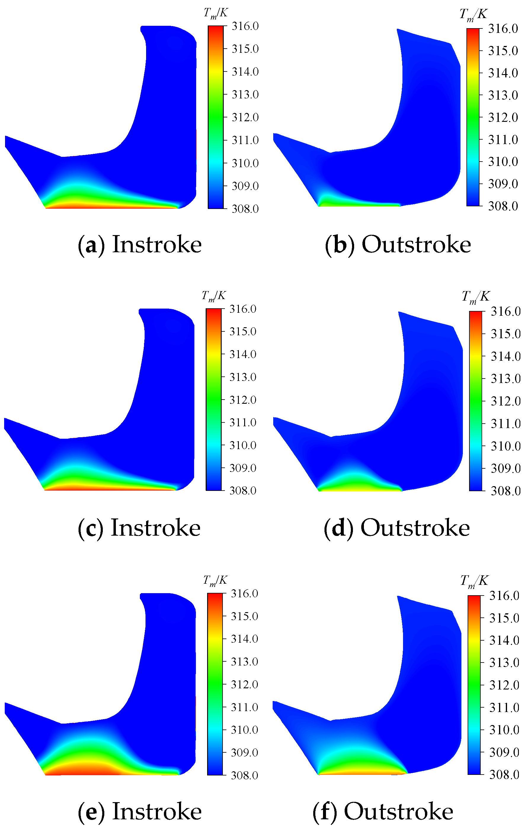
In this paper, it is assumed that the liquid film temperature follows a functional distribution in the direction of the film thickness. The problem is simplified to derive the average energy equation of the average temperature of the liquid film, and the oil temperature
T of the oil film in the sealing area is assumed to be a fourth-order function of the first position z in the direction of
h.
The liquid membrane temperature will be affected by the fluid viscosity shear and the microbulge contact shear friction, which are calculated by the following 3D energy equation:
The first term represents the liquid film heat transfer, the second term represents the liquid film convection heat transfer, the third term represents the liquid film viscosity shear heat, the fourth term represents the micro-convex body shear heat, the fifth term represents the transient heat source,
ρ represents the oil film density,
u represents the x, y, z directions for the liquid film velocity vector, and
Φ represents the energy dissipation density function, as follows:
Assuming that the specific heat capacity c of the oil film is a fixed value, the thermal conductivity k is independent of the film thickness direction, and the heat conduction of the oil film in the axial and circumferential directions is ignored. By introducing a continuity equation, the Equation (27) can be expressed as follows:
As mentioned above, the hydraulic ring in this study can be reduced to a one-dimensional axisymmetric model, so the average energy equation of the sealed interface oil film, considering fluid viscous dissipation, microbulgity contact shear friction, and the heat exchange of fluids with the sealing ring and the piston rod, can be expressed as follows:
where
c is the specific heat of the lubricant and
fc is the dry friction coefficient.
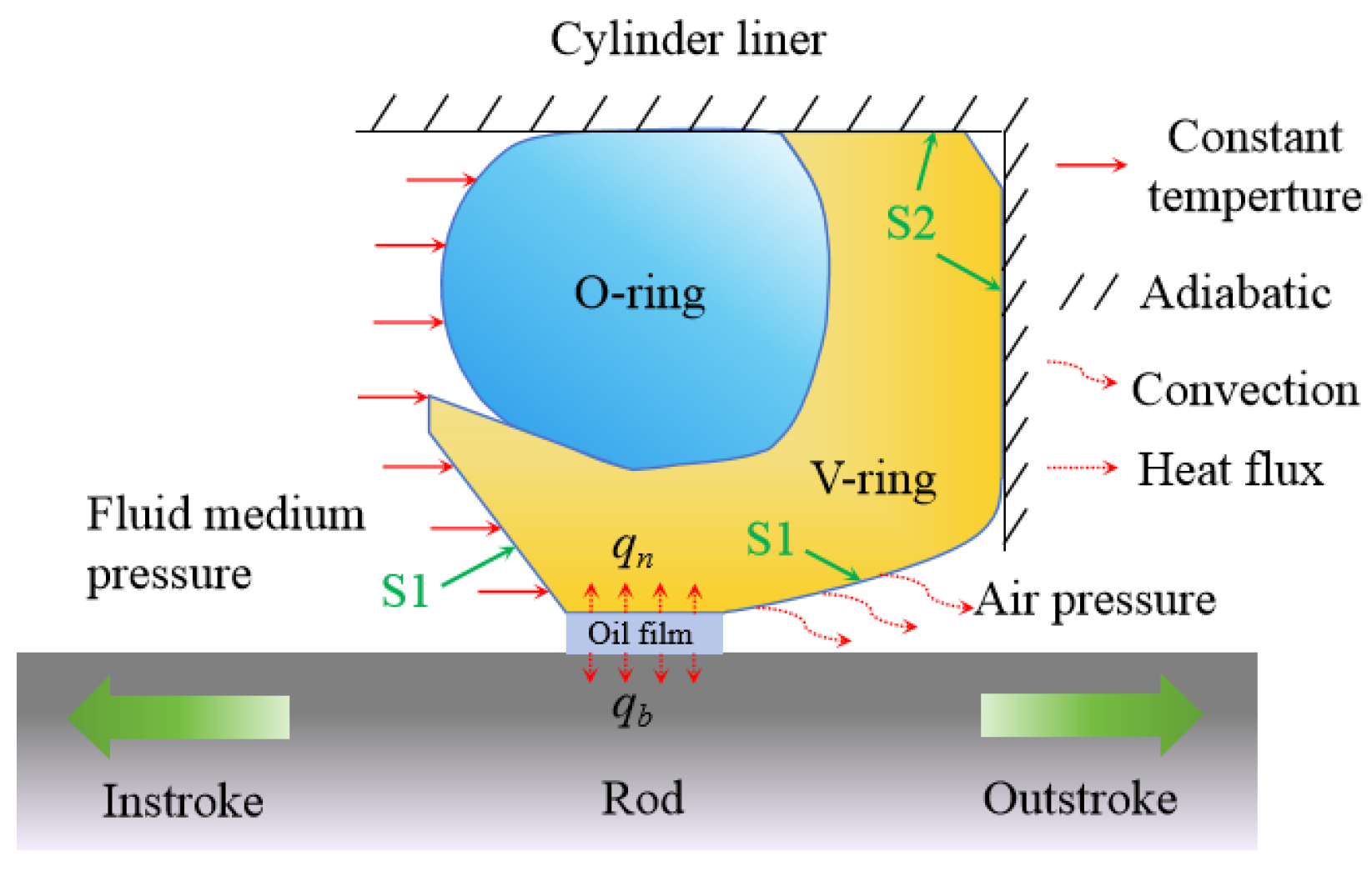
qn and
qb represent the local heat fluxes entering the V-shaped seal ring and the piston rod, respectively.
uh is the velocity vector of the hydraulic oil, which can be calculated using Formula (31).
k is the thermal conductivity of the oil film, which is the combined thermal conductivity of the oil–air mixture components due to cavitation, and can be calculated using Formula (32).
Φh is the average power dissipation density function of the entire fluid film, which can be obtained by the following expression in Formula (33):
where
kL and
kG are the thermal conductivities of hydraulic oil and air, respectively.
ρ and
ρL are the fluid cavitation mixing density and the complete fluid density, respectively.
According to Equation (26), the five coefficients a~e control the temperature field distribution of the whole sealing region; hence, the five governing equations for the temperature field function of the oil film are needed. In the sealed area, the local Cartesian coordinate system is adopted in Oxyz (
x is axial,
y is circumferential, and
z is membrane thickness). Suppose the piston rod surface (z = 0) temperature is fixed Trod, the seal ring surface temperature is
TSeal, and at z = 0 in Equation (29),
u = U and
u =
v = 0. The following five controlling equations involving the temperature field function of the liquid film are used:
where
Φ(0) and
Φ(h) represent the energy dissipation function of the oil film in the seal area on the piston rod and the seal ring surface, respectively, expressed using Equation (28):
In Equations (28) and (34)–(38), five coefficients a~e of the oil film temperature field T in the sealing area are expressed as follows:
The coefficients a~e are used to represent the functions of variables
Th,
TRod,
TSeal,
, and
. Except for
Th, the other parameters can be regarded as constant in the temperature solution process, so the solution for the temperature field distribution
T of the oil film in the sealing area can be simplified to determine the average temperature of the oil film
Th. Further, to solve average energy Equation (30), it is necessary to clarify the energy exchange between the oil film and the seal ring and the piston rods
qn and
qb. The basic formula of heat conduction can be used to establish the following equations:
When the hydraulic cylinder is working, the piston rod reciprocates, the surface sealing area of the piston rod can change at any time, and the sealing area in the same position needs a cycle to return. During this period, the heat of the piston rod will be fully exchanged with the fluid medium, so the surface temperature of the piston rod is equal to the temperature of the fluid medium. The following two-dimensional heat conduction method is used to derive the temperature field distribution of the sealing ring. This study considers the roughness effect of Gu et al. [
23] and Stefani et al. [
14]:
In Formula (48), kn and Tn represent the thermal conductivity and temperature of the V-shaped seal ring, respectively.
2.9. Hydraulic Reciprocating Seal Test Verification
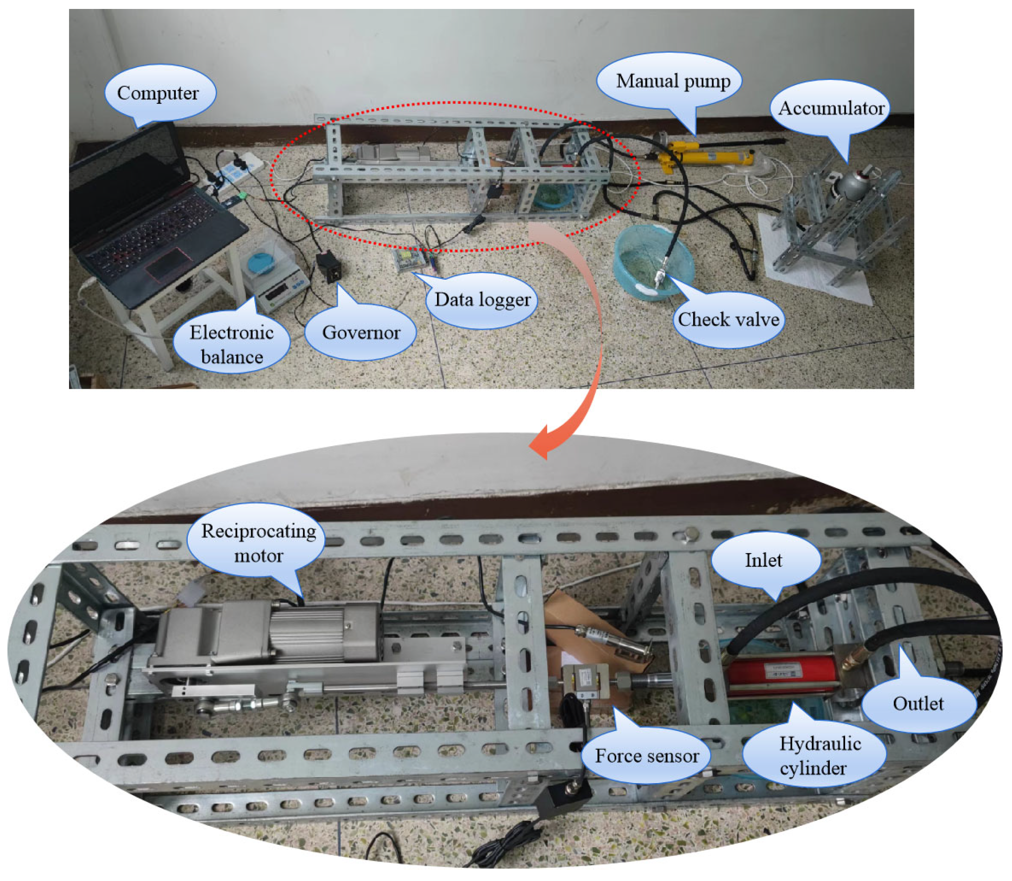
The entire experimental system consists of a power drive unit, a control unit, a data acquisition and analysis unit, and other parts. The test bench is shown in
Figure 5 and
Figure 6. The main structures include a motor, a tension and compression sensor, a manual hydraulic pump, a hydraulic cylinder, a collector, and a computer. The working process is as follows: disassemble the hydraulic cylinder; install a VL-type seal ring and reconnect it to the device; open the check valve; press the manual pump to allow the hydraulic oil to soak the entire cylinder until the hydraulic oil can flow out evenly from the check valve. Then, close the check valve, start pressing the manual pump, and observe the pressure gauge on the manual pump. When the target pressure is reached, stop pressing. Then, open the computer analysis software to start recording the friction force of the reciprocating rod, adjust the motor speed regulator to achieve the target reciprocating speed, and start collecting experimental data. After the collection is completed, organize the test instruments for future use.
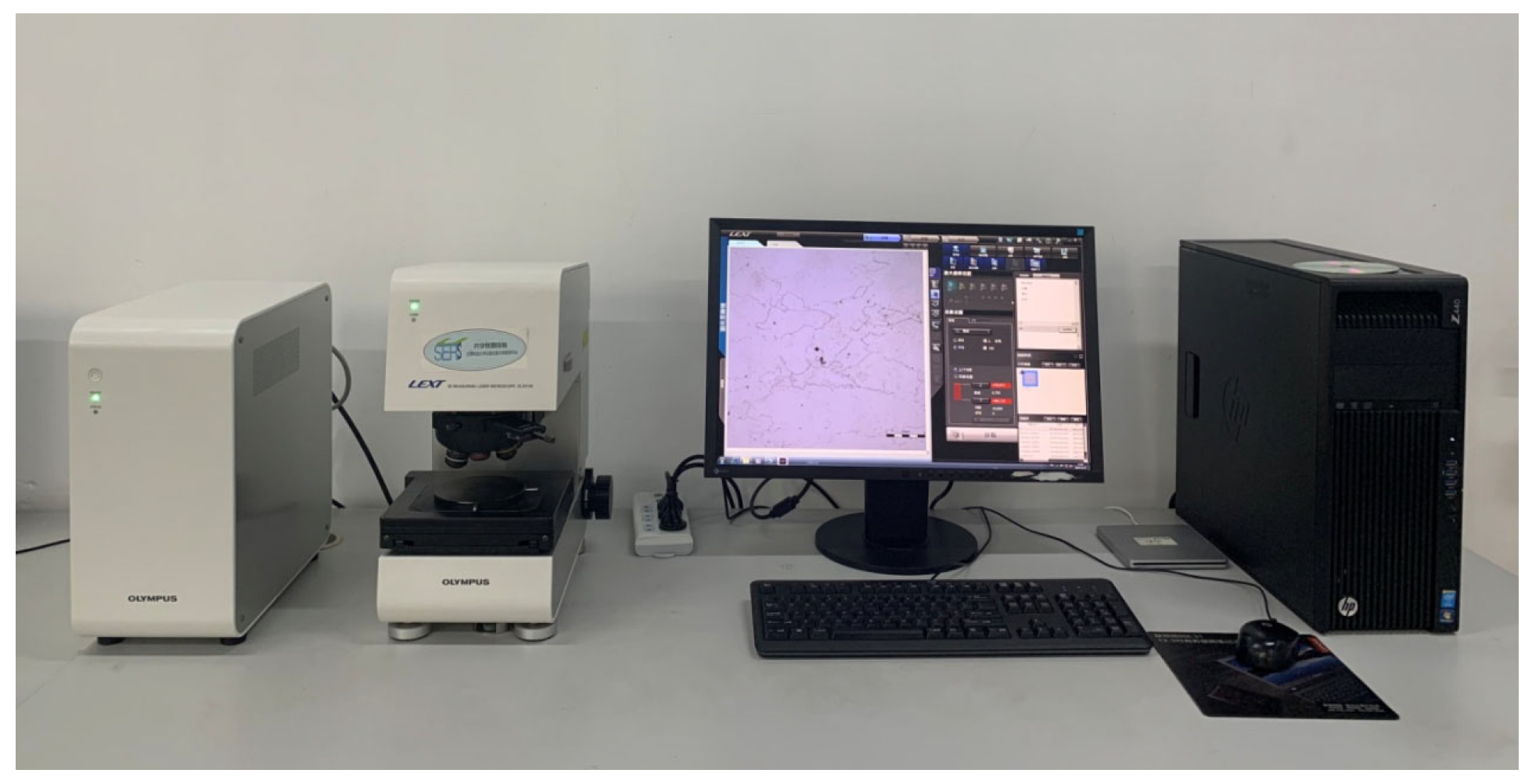
The RMS roughness was measured using an Olympus OLS4100 confocal optical microscope produced in Tokyo, Japan. The non-contact method allows for the observation and measurement of the sample’s surface in three dimensions. With a resolution of up to 10 nm, images can be obtained quickly and conveniently; see
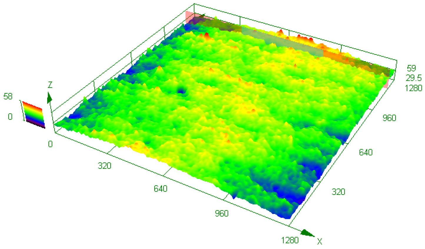
Figure 7. The microscopic surface contour morphology of the VL-sealed PTFE slip ring was obtained using the optical microscope. The sampling size was 1280 μm, and the surface morphology of the PTFE slip ring is shown in
Figure 8. The PTFE slip ring and surface morphology have an uneven, non-smooth surface. Through the rough contour height of a typical section of the PTFE sliding ring, the sliding ring surface can be calculated using the software calculation with the optical microscope. The surface roughness of the piston rod is much less than that of the PTFE sliding ring, so the surface roughness of the piston rod can be ignored.
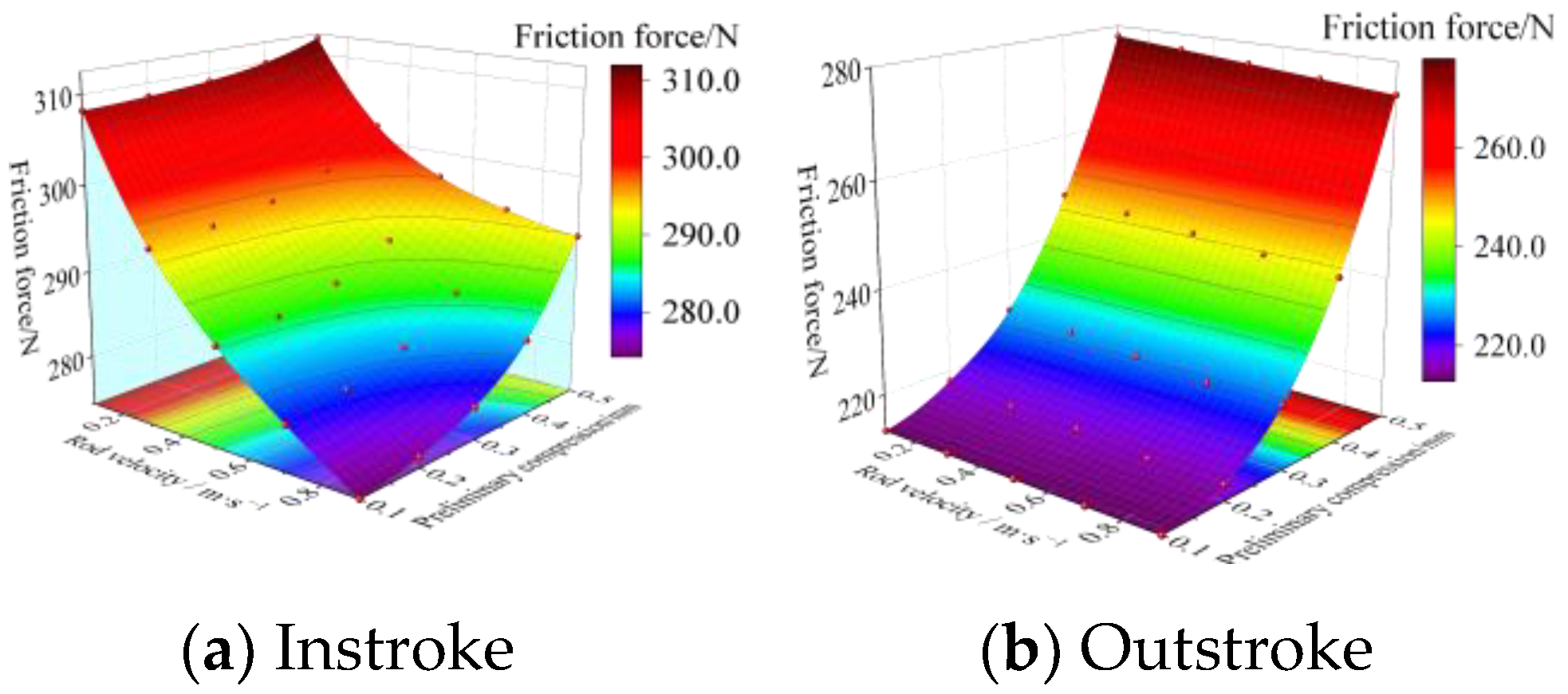
To ensure the correctness of the test, the average accuracy and standard deviation of the friction force of the piston rod reciprocating velocity prepress were calculated, as shown in
Table 2. The working conditions are as follows: the reciprocating speed of the piston rod was 0.2 m/s, the fluid pressure was 28 MPa, the sealing pre-compression was 0.1 mm, and the rms roughness was 1 μm.
In order to ensure the correctness of the test, the average accuracy and standard deviation of the friction force of the same piston rod’s reciprocating speed pre-compression are calculated.
As shown in
Table 2, although the results of 10 friction tests fluctuated within a small range, the standard deviation was only 2.34%, indicating that the bench can effectively measure the friction of reciprocating seals.
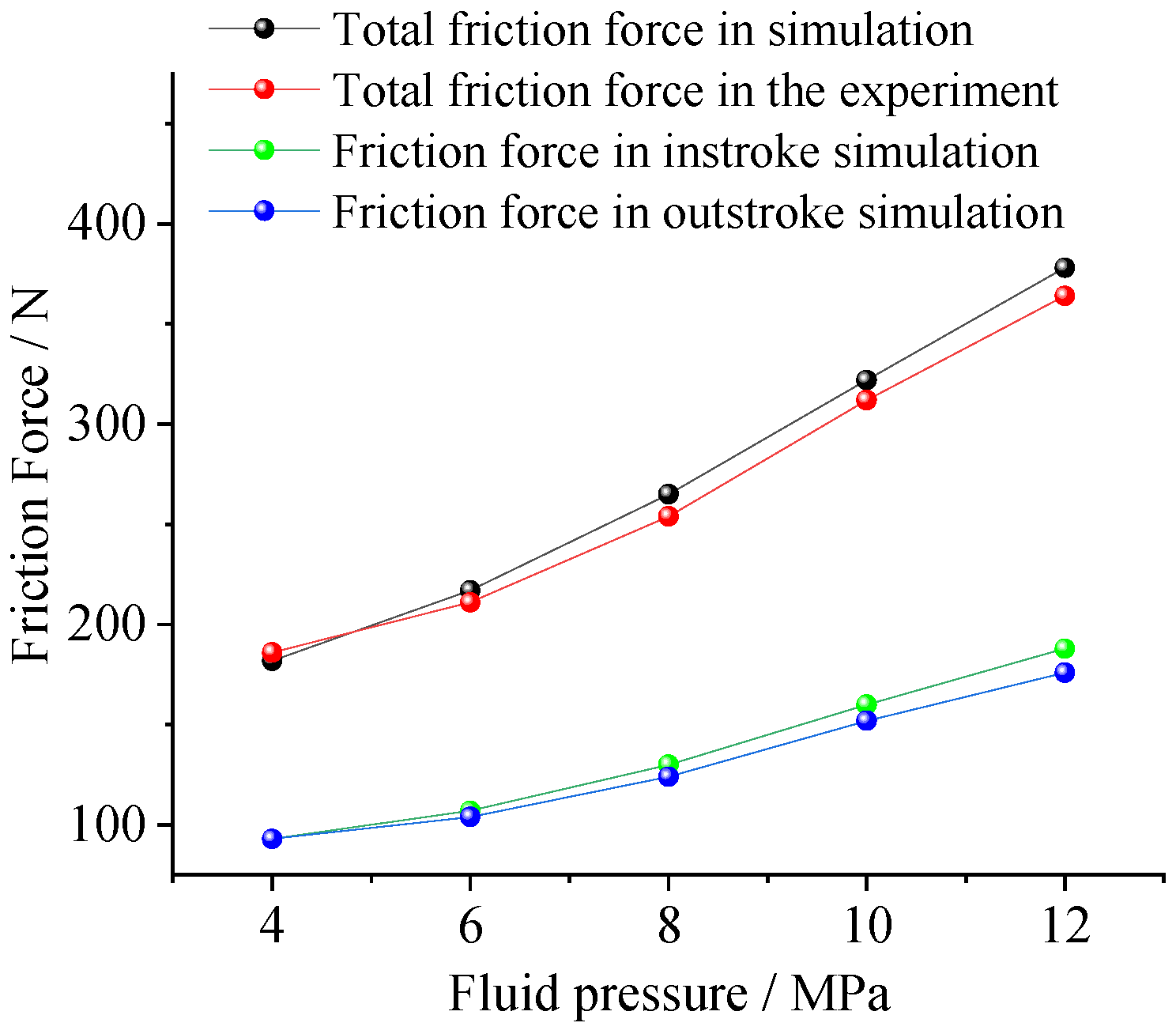
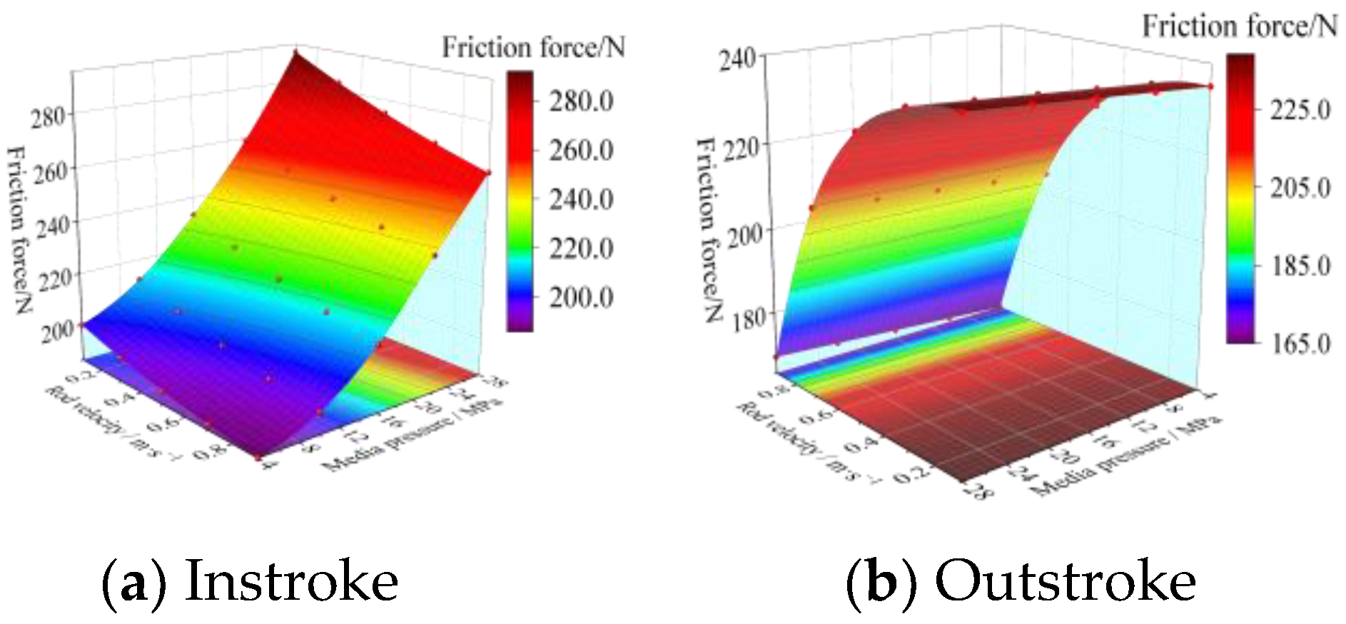
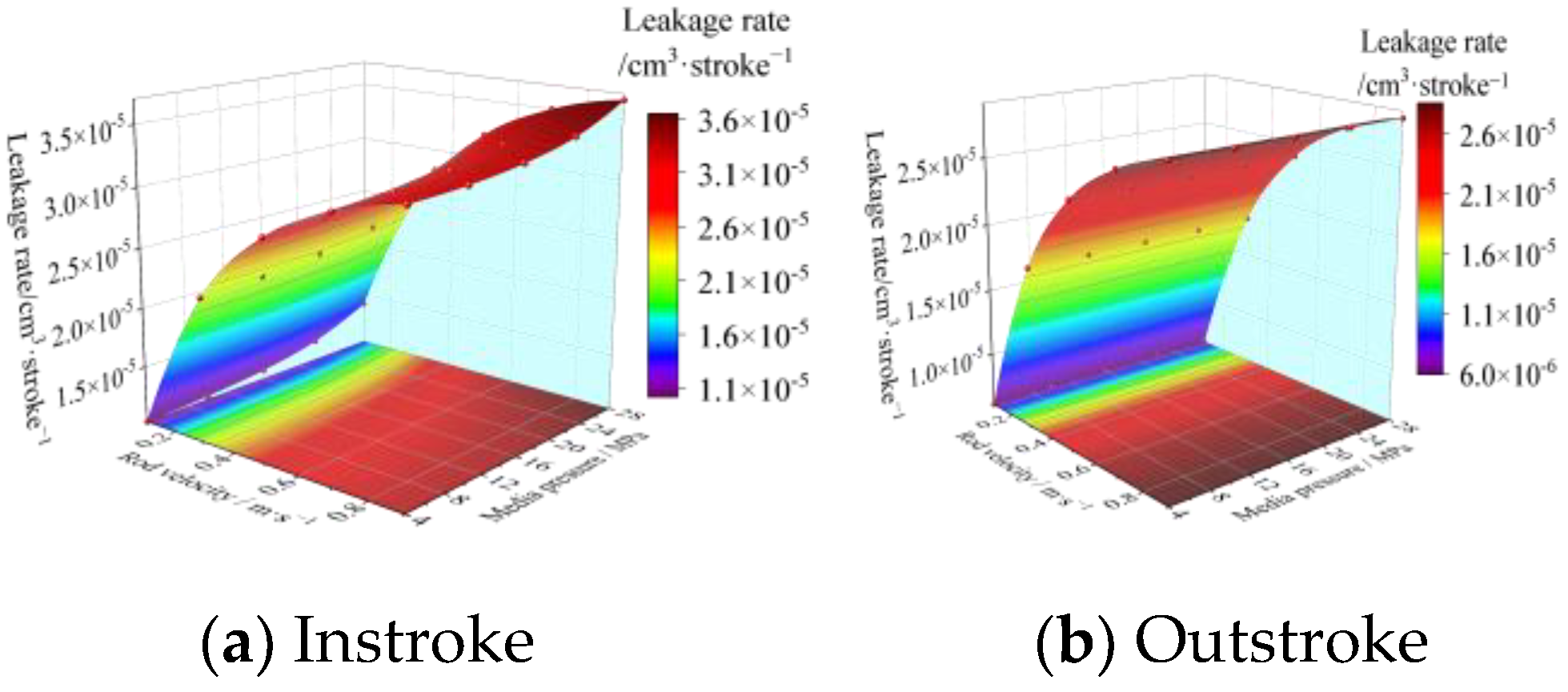
Figure 9 shows the friction force of the VL seal structure under five different fluid pressures when the speed of the piston rod is 0.1 m/s, and a comparison is made between the experimentally measured friction force and the friction force calculated by the mixed lubrication model. It can be seen from the figure that as the fluid pressure increases, the friction force of the instroke seal ring and the outstroke seal ring both show an approximately linear increasing trend. The instroke friction force calculated based on the mixed lubrication model is slightly larger than the outstroke friction force, which is similar to the conclusion obtained by Xiang et al. [
26]. In addition, the total friction force in the contact areas of the two seal rings increases with the increase in seal pressure, and the friction force law calculated using numerical simulation is basically the same as the experimental results. The friction force calculated based on the fluid dynamic inverse solution method has an average error of only about 3.9% compared with the experiment, which indicates that the numerical lubrication model used to study the friction and sealing characteristics of the VL seal structure has high reliability.
