Essay

Optimization Determination Method for the Explicit Equation of Scraper Motion Quantity in an Elliptical Rotor Scraper Pump

1
College of Mechanical and Electrical Engineering, Qingdao University, Qingdao 266071, China
2
Power Integration and Energy Storage Systems Engineering Technology Center (Qingdao), Qingdao 266071, China
*
Author to whom correspondence should be addressed.
Machines 2023, 11(9), 867; https://doi.org/10.3390/machines11090867
Submission received: 20 July 2023 / Revised: 21 August 2023 / Accepted: 22 August 2023 / Published: 29 August 2023
(This article belongs to the Section Electrical Machines and Drives)

Abstract

:
Addressing the inherent drawbacks of conventional positive displacement pumps, such as complex structure, poor sealing, low volumetric efficiency, and high noise, an innovative design of an elliptical rotor scraper pump (ERSP) was proposed. By segregating the pump chamber into high-pressure and low-pressure cavities, the scraper minimizes operational noise and significantly improves volumetric efficiency. To analyze the motion state of the ERSP, a mathematical model was established, determining the coordinated movement between the scraper and rotor using different optimization methods. The equations of coordinated action were derived and validated with relevant software through constraints applied to three algorithms and polynomial fitting. The flow field model of the ERSP was defined based on the established coordinated movement equation, and computational fluid dynamics (CFD) simulations were conducted to analyze pressure and velocity fields within the pump. A prototype of the ERSP was fabricated and tested, confirming its feasibility and advantages in enhancing fluid pressure and flow speed. This study provides valuable insights into the dynamic characteristics and structural optimization of fluid rotor pumps, contributing to anticipating and resolving potential faults and promoting the development of fluid power machinery.

1. Introduction

As indispensable general machinery for production and daily life, the positive displacement pump has numerous applications, such as chemical, food, pharmaceutical, metallurgy, domestic water supply, and more. However, due to increasingly stringent working requirements, it often needs to adapt to extreme working environments and transport specialized working media [1,2,3]. In recent years, pump devices have developed towards broader and more efficient operational ranges, higher power density, and lighter weight [4,5,6]. As global demands for energy-saving and emission reduction continue to increase, there is a growing need for exceptional new-principle positive displacement power machinery support.
Recent years have seen extensive research and innovation on positive displacement pumps, encompassing rotor profile design, pump structure, kinematic analysis, and flow field simulation. Wang et al. introduced an asymmetrical cycloid rotor for Roots pumps, enhancing design flexibility over traditional rotors [7]. Wu et al. developed a mathematical model for multi-stage “IVEC” type Roots vacuum pump rotors, improving design flexibility and pump performance [8]. Novel pump types like water hydraulic vane pumps, rotary clap pumps, positive displacement high-pressure vertical axis wind pumps, rotary distribution system plunger pumps, and Tritium Compatible Stainless Steel Roots Pumps have also emerged, addressing the drawbacks of traditional pumps [9,10,11,12,13].
Meanwhile, Guerra et al. [14] explored the design and performance of a balanced vane pump. They analyzed the kinematics of a double-lip vane pump, including its blade motion trajectory, velocity, and acceleration. At the same time, they also studied the geometric feasibility conditions of double-lip vane pumps, including lip spacing, lip length, and lip offset. Battarra et al. [15] first explored the kinematics of the balanced vane pump, studied the relationship between the geometry of the blade and the pump’s performance, and proposed a new design method to improve the efficiency and performance of the pump. Moreover, some scholars use fluid dynamics simulation to predict and improve pump performance. Choudhuri et al. [16] used CFD to simulate rotary positive displacement pump flow, studying the impact of tooth count on performance. Guo et al. [17] analyzed Roots pump efficiency under gas–liquid mixing, proposing strategies to mitigate efficiency reduction caused by reflux. Wang et al. [18] optimized electric submersible pump gap values for enhanced efficiency. Rong et al. [19] used CFD to scrutinize centrifugal pump performance, demonstrating its superiority over empirical methods. Vyavahare et al. [20] compared impeller velocity and pressure distribution using CFD and analytical predictions in a centrifugal pump. The methods of the above studies are of universal significance. However, in the application of machine learning and optimization techniques to pump design and performance prediction, Mao and others [21] proposed a machine-learning-based approach to predict the output performance of flexible electrohydrodynamic (EHD) pumps, addressing the limitations of traditional physical simulations. Three machine learning algorithms, including random forest regression, ridge regression, and neural network, were utilized to forecast critical parameters (pressure, flow rate, and power) using input data such as voltage, angle, gap, overlap, and channel height. M. Bashiri and others [22] have utilized improved artificial neural networks (ANN), evolutionary algorithms of particle swarm optimization (PSO), and validated CFD data to optimize the shape of centrifugal impellers, significantly enhancing the efficiency and head of centrifugal pumps.
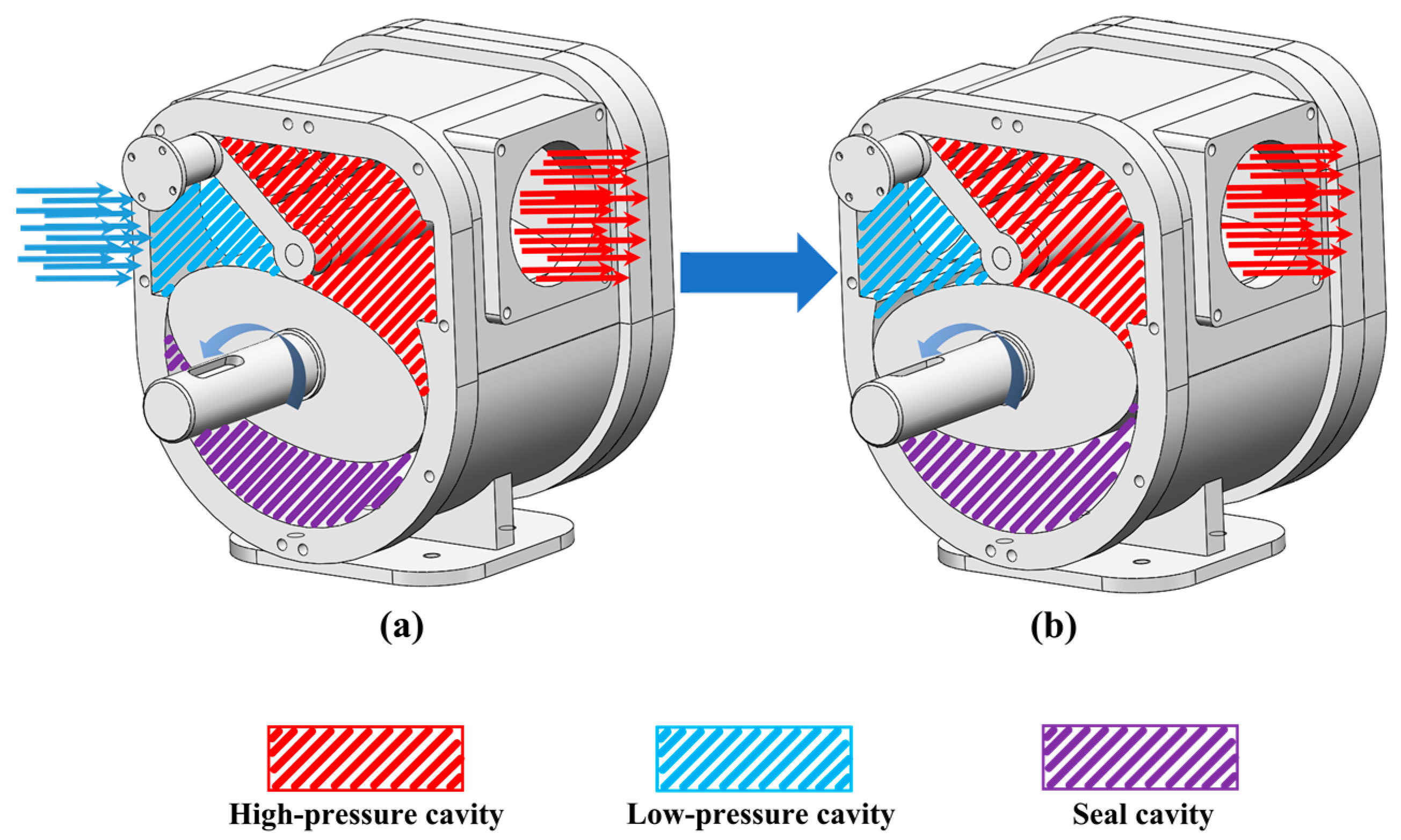
Based on the above research, Qingdao University proposed the structural principle of the scraper pump, and developed the ERSP, completed the study of the self-locking characteristics of the scraper, carried out motion simulation based on ADAMS, showing significant improvement in volumetric performance compared to the traditional Roots blower. However, due to its unique geometry, obtaining the displayed analytical equations between the ERSP swing scraper and the elliptical rotor is rugged, especially considering the oil film’s thickness or air gap during operation. However, many researchers have attempted to fit the relationship between the rotor trajectory and the swing scraper angle using the traditional polynomial regression method. However, this method has limited accuracy and does not accurately capture the coordinated motion relationship between the elliptical rotor and the swing scraper. Subsequently, it leads to adverse mesh volume problems when performing CFD simulations, which directly affects the continuity of numerical calculations and fundamentally hinders the implementation of simulations; on the other hand, the traditional polynomial regression method requires more data points to ensure the accuracy of the motion, which increases the computational effort.
Based on the above deficiencies, according to the cooperative motion relationship between the ERSP swing scraper and the elliptical rotor and taking into account the actual working clearance between the swing scraper and the elliptical rotor, the three methods of Exhaustive Search Method, sequential quadratic programming method, and BFGS-BM Method were tried and compared. Then, a high-precision explicit description of the motion trajectory and parameters of the swing scraper was obtained based on the proposed BFGS-BM Method. Finally, the flow field simulation and prototype experiment of ERSP were realized based on this method. The focus of this study was to provide an accurate equation of motion method for solving high-precision small-gap simulations, which is geometrically significant and provides a practical and effective solution for the simulation of complex fluid machinery such as ERSP.

2. ERSP Structure Principle and Scraper Position Equation

2.1. ERSP Structure Principle

The structural principle of the elliptical rotor scraper pump, as depicted in Figure 1, mainly comprises components such as the elliptical rotor shaft, swing scraper, and pump body. The working diagram of the ERSP fluid system is shown in Figure 2. The externally connected power drives the rotor shaft to rotate counterclockwise, and the scraper swings synchronously. As the rotor rotates, the volume of the low-pressure chamber increases, and low-pressure fluid enters the low-pressure chamber from the fluid inlet, which is transported to the high-pressure fluid chamber through the sealed chamber, and high-pressure fluid is discharged from the fluid outlet as the volume of the high-pressure fluid chamber decreases. The parameters of the elliptical rotor scraper pump prototype are shown in Table 1. Based on the Rated Flow and Rated Pressure specific to the application domain of the ERSP, the pump’s working volume and the design of pump chamber dimensions are calculated. After balancing displacement, pump dimensions, and mechanical stability, the long and short axis values, as well as the rotor thickness of the elliptical rotor, are deduced based on pump chamber dimensions and volume utilization coefficient. Ensuring that the swinging scraper length meets the requirements and remains more significant than the difference between the pump chamber radius and the minimum radius of the elliptical rotor’s circumferential surface, the lengths of the scraper and the radius of the primary arc diameter of the scraper are derived.

2.2. Equation of Elliptic Rotor Profile

In this section, the elliptical rotor type line equation is re-established as the general form of the elliptical curve. Figure 3 shows the transient model of the elliptical rotor scraper pump. The general form of the elliptical equation can be expressed as follows:
A x 2 + B x y + C y 2 + D x + E y + F = 0
where A, B, C, and F are all preset coefficients, and the values of D and E are 0.
As the elliptical rotor rotates, A, B, C, and F will also change. After the elliptical curve rotates counterclockwise by θ degrees, the equation of the elliptic rotor curve is:
( x cos ( θ ) y sin ( θ ) ) 2 a 2 + ( y cos ( θ ) + x sin ( θ ) ) 2 b 2 1 = 0
As shown in Figure 3, point B is the center of the swinging scraper head. Angle α represents the angle between the swinging scraper and the horizontal direction, and l represents the distance between points A and B. The coordinates of point A are given as (xA, yA), and let us assume the coordinates of point B are (xB, yB). Therefore, the equation describing the motion trajectory of the center of the scraper head is:
x B = x A + l cos ( α ) y B = y A + l sin ( α )
The distances d between point B and point Q can be expressed as follows:
d = y y B 2 + x x B 2
The minor distance d should be when point Q is just the contact point between the elliptical rotor curve and the big head of the scraper. Take the derivative of Equation (4) concerning the implicit function to obtain:
d = ( y y B ) y + ( x x B ) ( y y B ) 2 + ( x x B ) 2
When d is the minimum distance, i.e., when d′ = 0, we can obtain:
y = ( x x B ) y y B
Take the derivative of the general Equation (1) of the elliptical rotor curve equation concerning x to obtain:
2 A x + B y + B x y + 2 C y y + D + E y = 0
Collect Equations (6) and (7) and simplify the above equations. Simplify to get:
2 A x + B y + D B x + 2 C y + E = x x B y y B
Solve Equations (1) and (8) together:
2 A x + B y + D B x + 2 C y + E = x x B y y B A x 2 + B x y + C y 2 + D x + E y + F = 0
To further determine the relationship between the angle of rotation of the elliptical rotor and the angle of the swing scraper, a straightforward approach is to analyze Equation (9) simultaneously. However, the practical situation consists of an oil film gap between the elliptical rotor and the scraper, which makes their engagement beyond simple meshing. Therefore, more than just geometric relations and analytical methods must be needed to solve this problem. For this reason, in this paper, a numerical fitting method was used to first obtain multiple pairs of reliable relations between the swing angle of the scraper and the rotation angle of the elliptical rotor by an optimization method. Then, a polynomial fitting was performed to satisfy the conditions.

3. Optimization Method for the Motion Trajectory

Based on the preceding theoretical analysis and mathematical derivation, it was determined that numerical fitting and polynomial fitting should be employed to tackle the issues regarding the dynamic motion trajectory and equations of the elliptical rotor and swing scraper. This section introduces or proposes three methods for determining the motion trajectory and equations.

3.1. Exhaustive Search Method

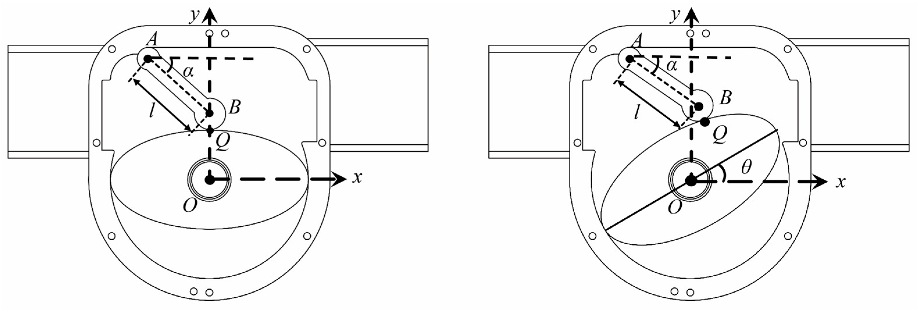
For solving this problem, the most widely used method is the ergodic search method. Before embarking on an exhaustive search for solutions, it is necessary to initially define the range of values for the independent variables in the motion equation: the rotational angle (θ) of the elliptical rotor and the oscillating angle (α) of the swing scraper. Subsequently, a compromise is made to set the computational step size for θ as ten and for α as 0.01 in the exhaustive search method to balance computational accuracy and efficiency.
In this paper, in order to avoid encountering spurious intersections between the scraper circle and the elliptical rotor surface during the exhaustive search process, this study traversed all the points on the trajectory of the scraper head’s motion. It calculated the corresponding α value for each point. Additionally, due to the absence of direct contact between the elliptical rotor and the scraper circle, with gaps typically ranging from 0.02 mm to 0.04 mm, a constraint of 0.02 ≤ dij − r ≤ 0.04 was imposed during the solving process, where r denotes the radius of the scraper circle. The calculation results that did not satisfy this constraint and were, thus, are discarded. Finally, the least squares method performed polynomial fitting on all α and θ data that met the constraint criteria obtained from the exhaustive search method.
For the traditional exhaustive search method, to constrain the magnitude of the fluctuation of dij, it can only try to minimize the solution step size of the variables θ and α. Therefore, this method’s convergence speed and efficiency may be limited when dealing with complex problems. In the subsequent discussion, a more efficient adjustment to the variable step size was achieved by introducing a theoretically superior sequential quadratic programming algorithm. This method can effectively reduce the magnitude of fluctuations in the computation, which improves the convergence performance of the algorithm and enables the algorithm to obtain a stable solution in a shorter time.

3.2. Sequential Quadratic Programming (SQP) Algorithm

The gap between the elliptical rotor and the swing scraper should remain stable and within a reasonable range, and, hence, controlling this gap is of utmost importance. In the case of the Sequential Quadratic Programming algorithm’s case, to constrain the fluctuation amplitude of the gap dij obtained through computations, it is first perceived as an optimization problem. The objective function of this problem is defined as:
min f ( d ) = d max d min
Herein, dmin = min{dij} signifies the minimum distance from the swing scraper’s larger end center to the elliptical rotor’s surface. In comparison, dmax = max{dij} denotes the maximum distance from the swing scraper’s larger end center to the elliptical rotor’s surface. The values of dij are derived from the exhaustive search method presented in the preceding section.
s . t .0.02 d ij r 0.04 ( i = 1 , 2 , , 5000 ; j = 1 , 2 , , 19 )
Compared with the exhaustive search method, the Sequential Quadratic Programming algorithm strategically determines the values for the rotational angle θ of the elliptical rotor and the swing angle α of the swing scraper. The problem-solving idea is to first simplify the objective function of the optimization problem into a quadratic programming problem based on the Taylor expansion series and the constraints into linear functions at each iteration point. Subsequently, the optimal solution obtained from solving the quadratic programming problem at each step is used as the search direction for the next step. This process is repeated until the optimal solution to the original problem is found.
However, theoretically, the SQP algorithm needs to solve multiple quadratic programming subproblems at each iteration step, which makes it difficult to fully utilize the sparsity and symmetry of the original optimization problem, resulting in a large amount of computation and data storage. The calculation efficiency is not ideal. The optimization problem described in this section takes 11,817.5 s to converge. To further compress the solution time of the optimization problem shown in Equation (10) while ensuring the accuracy of the gap control, the following combines the BFGS method and the BM method to propose a theoretically more efficient solution method, which is henceforth referred to as the BM-BFGS method for convenience.

3.3. BFGS-BM Method

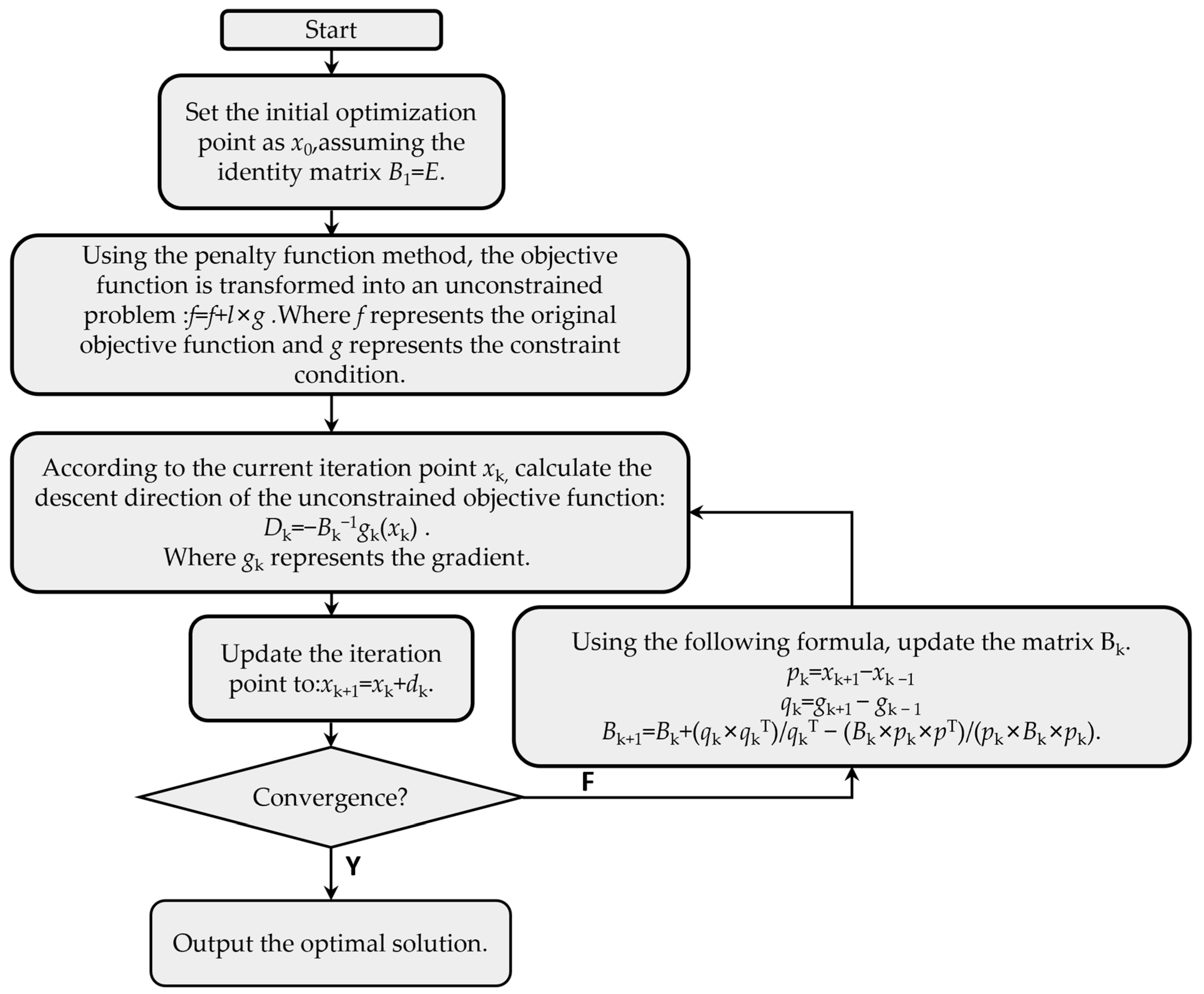
The Broyden–Fletcher–Goldfarb–Shanno (BFGS) method is one of the most efficient techniques for solving non-linear, unconstrained optimization problems. This approach negates the need to compute the Hessian matrix of the optimization problem, instead constructing an approximation of a positive-definite symmetric matrix based on the BFGS conditions. Consequently, it has a convergence speed closely resembling the Newton method and significantly reduces the computational requirements compared to the latter. However, because the BFGS method is inherently designed for unconstrained optimization problems, it is unsuitable for the constrained optimization problem denoted as Equation (10) in this paper. Hence, this study combines the penalty function and the BFGS methods to solve Equation (2). The process of the BFGS-BM method is illustrated in Figure 4. The strategy adopted involves treating the constraints as penalty terms in the objective function and introducing a comparatively large penalty coefficient, M. This allows the constrained problems illustrated by Equations (10) and (11) to be transformed into unconstrained optimization problems, as demonstrated below:
min f ( d ) = ( d max d min ) + M × max ( ( d ij r 0.04 ) , 0 ) + M × max ( ( 0.02 d ij + r ) , 0 )

4. Simulation Results and Comparative Analysis

Numerical simulations and polynomial fitting processes were carried out based on the exhaustive search method, the SQP algorithm, and the BFGS-BM method proposed in Section 3, all attempting to control the gap between the elliptical rotor and the swing scraper. This section presents a comparative analysis of the simulation results for these three methods.
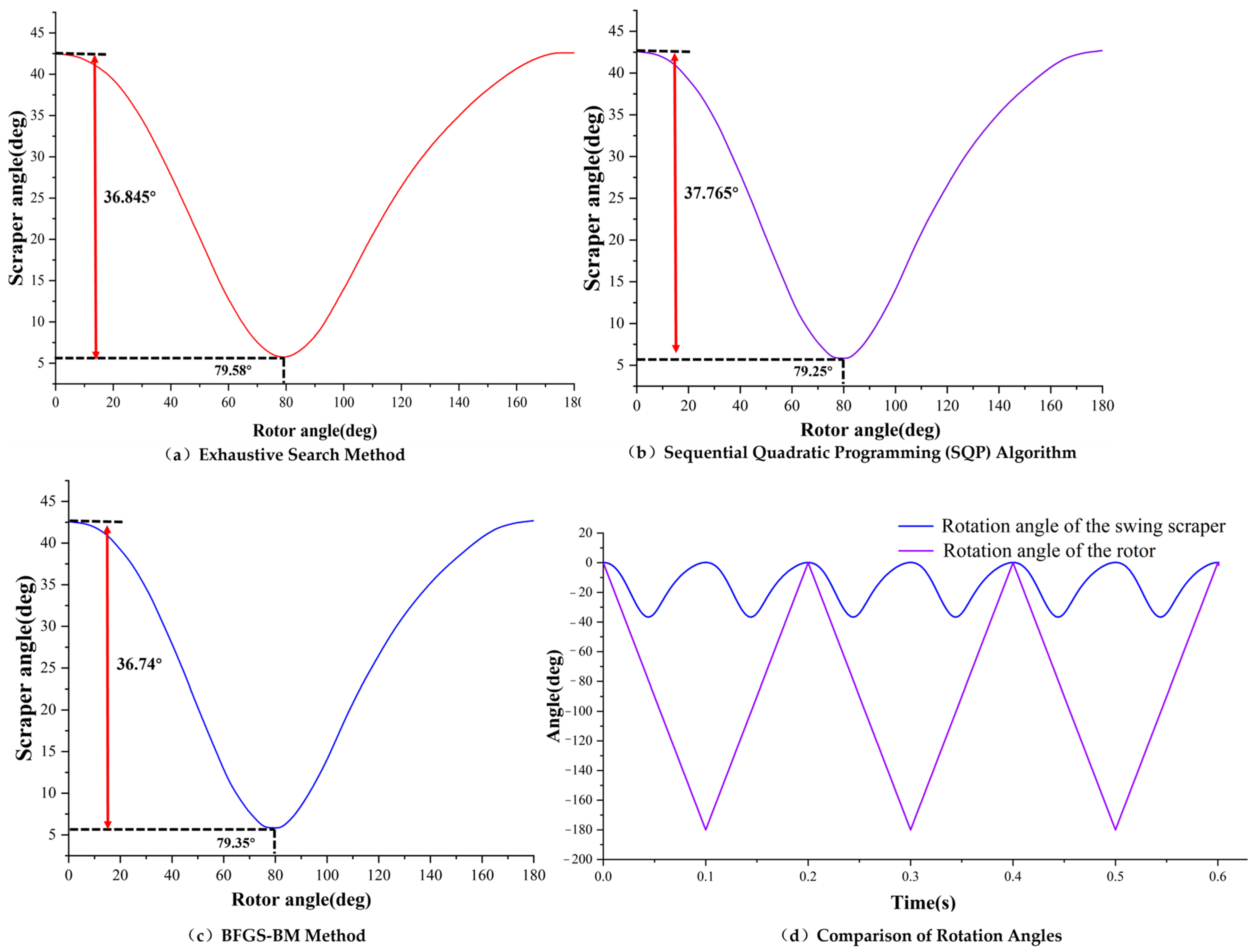
The simulation involves utilizing the exhaustive search method to acquire relevant data and perform the fitting. Figure 5 illustrates the relationship between the elliptical rotor’s rotational angle (θ) and the swing scraper’s swinging angle (α) under three search methods. Figure 5a represents the exhaustive search method, with the rotor angle (θ) reaching a limit of 79.58° and the scraper achieving an oscillation of 36.845°. Figure 5b displays the relationship under the sequential quadratic programming algorithm, with the rotor angle (θ) reaching a limit of 79.25° and the scraper oscillating at 37.765°. Finally, Figure 5c describes the relationship under the BFGS-BM method, with the rotor angle (θ) reaching a limit of 79.35° and the scraper oscillating at 36.74°. Figure 5d shows the operation of the oscillating scraper with the rotor for the first three cycles solved by Adams simulation software. In one cycle, the maximum swing range of the scraper was 36.74°. Considering the influence of the gap width between the two, the maximum angle obtained by the simulation was the same as that obtained by the BFGS-BM solution, which verifies the correctness of the solution method.
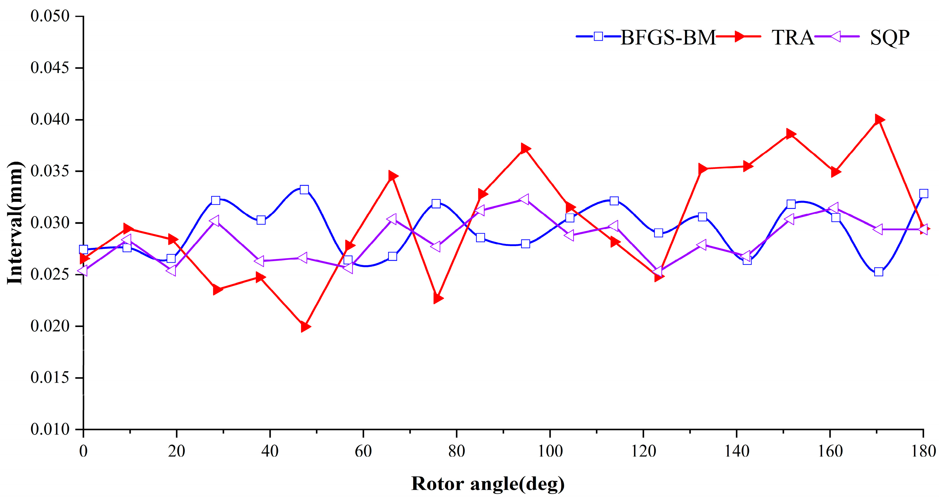
Figure 6 illustrates the relationship between cycle count and gap width under three search methods. Within controllable computational constraints, the exhaustive search method utilized a larger variable step size to establish the potential correlation between the elliptical rotor’s rotational angle and the swing scraper’s angular position relative to the x-axis. However, due to the larger step size, limited precision led to significant fluctuations in calculated gap values (dij). The maximum gap reached 0.039 mm, deviating from the actual gap. During the simulation of the sequential quadratic programming algorithm, the oscillation range of the gap between the elliptical rotor and the swing scraper was 0.025 mm to 0.0321 mm, with a fluctuation amplitude of 0.0071 mm and a fluctuation coefficient of 0.24 significantly smaller than the 0.019 mm obtained from the exhaustive search method. This confirmed the higher precision of the sequential quadratic programming algorithm in solving the problem, as the gap width stabilized within a more suitable range for the design requirements of the elliptical rotor scraper pump. For the solution obtained under the BFGS-BM method, the oscillation range of the gap between the elliptical rotor and the swing scraper was 0.025 mm to 0.0331 mm, with a fluctuation amplitude of 0.0081 mm and a fluctuation rate of 0.31. This amplitude was smaller than that obtained through the exhaustive search method, affirming the feasibility of the BFGS-BM method.
According to the solution results and comparative analysis of the exhaustive search method, sequential quadratic programming method, and BFGS-BM method, the solution speed of the exhaustive search method is the fastest, the BFGS-BM method is the second fastest, and the solution speed of the sequential quadratic programming method is the slowest. This chapter uses the variation range of the gap between the elliptical rotor and the swing scraper (dmax −  dmin) as the robustness evaluation index. In terms of the robustness of the calculation results, the sequential quadratic programming method is the most robust, the BFGS-BM method is the second, and the exhaustive search method is the worst. Compared with the traditional algorithm, the BFGS-BM method improves the computational efficiency by 29.25% and reduces the gap fluctuation rate by 42.63%. Combining computational efficiency and accuracy, this paper controls the mesh motion in the computational domain model through the BFGS-BM solving results to realize the numerical simulation. Table 2 compares the computation time and robustness of the three methods.
According to the BFGS-BM method, multiple pairs of scraper swing Angle and ellipse rotation Angle are obtained, and the least square method is used to fit, and the fitting equation of Angle α is obtained:
α = a 1 sin ( b 1 θ + c 1 ) + a 2 sin ( b 2 θ + c 2 ) + a 3 sin ( b 3 θ + c 3 ) + a 4 sin ( b 4 θ + c 4 )
Among them: a1 = 29.32, b1 = 0.00191, c1 = 1.881, a2 = 18.09, b2 = 0.03609, c2 = 1.809, a3 = 2.291, b3 = 0.7812, c3 = −1.176, a4 = 0.2511, b4 = 0.2511, c4 = −0.5408.
Based on the above analysis, by deriving the time of the elliptical rotor rotation angle equation, the relationship between the rotation speed of the elliptical rotor and the scraper angular speed can be obtained, as follows:
ω 1 = a 1 b 1 ω 2 cos b 1 ω 2 t + c 1 + a 2 b 2 ω 2 cos b 2 ω 2 t + c 2 + a 3 b 3 ω 2 cos b 3 ω 2 t + c 3 + a 4 b 4 ω 2 cos b 4 ω 2 t + c 4
where a1, b1, c1, a2, b2, c2, a3, b3, c3, a4, b4, and c4 can be obtained from Equation (13), ω1 is the angular speed of the swing scraper, and ω2 is the angular speed of the elliptical rotor.

5. Flow Field Analysis and Prototype Manufacture and Testing of ERSP

In this chapter, the BFGS-BM method was applied to derive the synergistic equations of motion (angular velocity equations) for the elliptical rotor and the swing scraper, which are written as user-defined functions (UDF) to regulate the mesh motions in the computational domain model. Subsequently, numerical simulations of the flow field of the elliptical rotor scraper pump were realized. Ultimately, the accuracy of the derived synergistic equations of motion for simulation under high-precision and small-gap conditions was further verified by comparing the numerical simulation results with the actual test data of the ERSP prototype.

5.1. Internal Pressure Field Analysis

In order to investigate the change rule of the internal pressure field of an elliptical rotor scraper pump under different elliptical rotor speeds, in this section, the internal pressure field will be analyzed by flow field simulation, and the fluid medium type was set to air. In this section, the elliptical rotor speed was set to 600 r/min. After the grid independence test, the ERSP grid model of 2.245 million was finally selected, and the maximum grid size of the fluid region was 2 mm. The 2.5-dimensional grid reconstruction method was adopted, and the cooperative equation of motion was derived through the BFGS-BM method, which was written as a UDF to control the grid motion. The transient computational time step was 10-4. RNG k-ε is a turbulence model. The coupled pressure and velocity were calculated by the SIMPLE method.
As shown in Figure 7, when the elliptical rotor was in a horizontal position, the pressure in the space connected to the inlet was close to 1000 Pa, which is the inlet pressure. The pressure in the space connected to the outlet was close to 6000 Pa, which is the outlet pressure. With the elliptical rotor’s rotation, the outlet part’s volume was squeezed, and the pressure at the outlet further increased. Under 600 r/min, the maximum outlet pressure can reach about 8500 Pa. Furthermore, the pressure at the contact point of the elliptical rotor and the swing scraper was the smallest, which is due to the rapid expansion of the space distribution of the compressed fluid in the compression process of the elliptical rotor and the swing scraper, causing a sudden drop in instant pressure and the appearance of a blue area. Similarly, the pressure value at the contact point of the elliptical rotor and the pump chamber wall was also smaller, which is due to the high-speed backflow easily formed at the gap between the elliptical rotor and the pump chamber wall, causing a larger flow speed in the gap, thereby promoting the conversion of pressure to kinetic energy and the appearance of a green area.

5.2. Velocity Vector Distribution

As shown in Figure 8a, the flow on the fluid inlet side was relatively stable, and the flow inside the high-pressure chamber on the fluid outlet side was relatively turbulent, with certain vortices existing. As shown in Figure 8b, the vortex in the high-pressure chamber gradually decreased after the swing scraper rotated to the limit position. As shown in Figure 8c, as the elliptical rotor continued to rotate, the low-pressure chamber and the sealing chamber gradually communicated, the volume increased, and the low-pressure fluid was introduced into the low-pressure chamber. As shown in Figure 8d, when the elliptical rotor rotated to the termination position, the flow speed inside the entire pump chamber slowed down. At this time, the elliptical rotor pump completed a cycle of work.

5.3. Manufacturing and Testing of the Prototype

An elliptical rotor scraper pump prototype was manufactured and tested based on theoretical analysis, model construction, kinematic analysis, and flow field analysis. With the unremitting efforts of the whole team, a prototype was developed and successfully put into use in the transportation of the particular gas industry. Figure 9 displays the associated manufacturing process. The rotor shaft of the prototype was connected to an alternating current motor, and the motor was set to a constant speed output. The input medium was air.
Ensuring follow-up capacity and to further verify the rationality of the structural principles of the elliptical rotor scraper pump and the accuracy of the flow field analysis, this section further tested the prototype to obtain the outlet pressure and flow rate under different rotor speeds. To compare the numerical simulation with the results of the flow field, the prototype test was carried out at rotor speeds of 600 r/min, 900 r/min, and 1200 r/min. To make the test data more accurate, a multi-group measurement method was adopted, and five sets of tests were conducted. The average value of the five sets of test data was taken as the final test data. The prototype structure was fundamentally consistent with the three-dimensional model on which the flow field analysis was based. However, minor differences due to engineering design issues will have some impact on the test results. Hence, there will be a discrepancy between numerical simulation data and test data, but theoretically, as long as the error between the two is within 5%, it is considered that they can mutually corroborate. The test data (outlet pressure and outlet flow rate) are shown in Table 3 and are compared with the flow field simulation data. The results indicate that the deviation between the data was within the permissible range, verifying the accuracy of the flow field analysis and demonstrating the rationality of the structural principles of the elliptical rotor scraper pump and its potential to increase fluid pressure.
In Table 4, this paper compares ERSP with three-blade Roots pump in terms of pressure boost and outlet flow. Compared to the three-blade Roots pump, the ERSP had advantages in terms of maximum pressure boost and flow rate, which can deliver a larger flow rate and produce a greater pressure level. This means that ERSP can handle more fluids more efficiently per unit of time, resulting in a wider range of applications requiring high flow rates. This performance advantage was due to the unique structural design and motion coordination of the ERSP and its high volumetric efficiency. Compared to the three-blade Roots pump design, the ERSP enables greater flow output while maintaining stability by optimizing movement and structural layout.

6. Conclusions

This paper proposed the kinematic solution method of elliptical rotor scraper pump (ERSP) for the first time. Firstly, we aimed to determine the motion trajectory and cooperative motion equations of the elliptical rotor and the swinging scraper. The dynamic motion problem was transformed into a clearance control problem for the elliptical rotor and the swinging scraper. The exhaustive Search Method, sequential quadratic programming method, and BFGS-BM method were introduced and proposed to realize the gap control. Subsequently, the feasibility of the proposed algorithm was verified by simulation examples based on the dynamic motion trajectories and equations of the elliptical rotor scraper pump. Finally, based on the analyzed results, a prototype elliptical rotor scraper pump was fabricated and tested. The developed method obtained analytical solutions by simple mathematical derivations. The time required for each operation was finite and quantifiable and, thus, the methodology of this paper can be applied to high-precision, small-clearance volumetric pumps. In addition, the synergistic kinematic equations can be used to determine the dynamic response characteristics of the pump, providing a valuable basis for pump design and optimization, which will help to gain a deeper understanding of the development trend of fluid power machinery and provide essential theoretical guidance and practical support for research and engineering applications in related fields.

Author Contributions

Conceptualization H.Z.; methodology, M.L. and H.Y.; software, M.L. and Z.Z.; validation, Z.Z., M.L. and H.Y.; formal analysis, Z.Z.; investigation, Z.Z.; resources, H.Z.; data curation, Z.Z., M.L. and H.Y.; writing—original draft preparation, M.L.; writing—review and editing, Z.Z. and H.Y.; visualization, M.L.; supervision, Z.Z. and H.Y.; project administration, H.Z.; funding acquisition, H.Z. All authors have read and agreed to the published version of the manuscript.

Funding

This research was funded by the National Natural Science Foundation of China, grant number 52075278, and the Municipal Livelihood Science and Technology Project of Qingdao, grant number 19-6-1-92-nsh.

Data Availability Statement

Not applicable.

Conflicts of Interest

The authors declare no conflict of interest.

References

  1. Josifovic, A.; Corney, J.; Davies, B. Valve dynamics in multi-cylinder positive displacement pump model. In Proceedings of the 2015 IEEE International Conference on Advanced Intelligent Mechatronics (AIM), Busan, Republic of Korea, 7–11 July 2015; pp. 35–41. [Google Scholar]
  2. van Rijswick, R.; Talmon, A.; van Rhee, C. Fluid structure interaction (FSI) in piston diaphragm pumps. Can. J. Chem. Eng. 2016, 94, 1116–1126. [Google Scholar] [CrossRef]
  3. Zhao, F.; Zhang, S.-W.; Han, F.; Li, R.-D. Thermodynamics Analysis of Roots Vacuum Pump. J. Phys. Conf. Ser. 2020, 1519, 012016. [Google Scholar] [CrossRef]
  4. Shcherba, V.E. Preliminary Crankshaft Speed Assessment for a Reciprocating Hybrid Power Machine with Regenerative Heat Transfer in Compressor and Pump Modes. Russ. Eng. Res. 2023, 43, 529–533. [Google Scholar] [CrossRef]
  5. Shapin, S. Pump and circumstance: Robert Boyle’s literary technology. Soc. Stud. Sci. 1984, 14, 481–520. [Google Scholar] [CrossRef]
  6. Zhang, Z. Hydraulic Characteristics of Pumps and Turbines. Hydraul. Transients Comput. 2020, 235–272. [Google Scholar] [CrossRef]
  7. Wang, J.; Yang, S.; Sha, R.; Li, H.; Xu, C. Geometric Design and Analysis of Novel Asymmetrical Rotors for Roots Vacuum Pumps. J. Mech. Des. 2019, 142, 064501. [Google Scholar] [CrossRef]
  8. Wu, Y.-R.; Tran, V.-T. Generation method for a novel Roots rotor profile to improve performance of dry multi-stage vacuum pumps. Mech. Mach. Theory 2018, 128, 475–491. [Google Scholar] [CrossRef]
  9. Keisar, D.; Eilan, B.; Greenblatt, D. High Pressure Vertical Axis Wind Pump. J. Fluids Eng. 2021, 143, 051204. [Google Scholar] [CrossRef]
  10. Wu, X.; Sun, K. Research on a New Type of Water Hydraulic Vane Pump. In Proceedings of the 2015 International Conference on Fluid Power and Mechatronics (FPM), Harbin, China, 5–7 August 2015; pp. 638–642. [Google Scholar]
  11. Shim, S.-B.; Park, Y.-J.; Nam, J.-S.; Kim, S.-C.; Kim, J.-M.; Kim, K.-U. Development of a rotary clap mechanism for positive-displacement rotary pumps: Pump performance analysis. Int. J. Precis. Eng. Manuf. 2017, 18, 575–585. [Google Scholar] [CrossRef]
  12. Wang, W.G.; Mucino, V.H.; Smith, J.E.; Lyons, D.W. Kinetostatic Modelling of an Unconventional Motion Conversion Mechanism in Application of a Plunger Pump System. Proc. Inst. Mech. Eng. Part C J. Mech. Eng. Sci. 1992, 206, 19–27. [Google Scholar] [CrossRef]
  13. Banerjee, I.; Schopphoff, A.; Hughes, S.; Pearce, R.; Nasluzov, S. Experimental Investigation of Tritium Compatible Stainless Steel Roots Pumps: Part 2: Validation, qualification and definition of modifications in real application. Vak. Forsch. Und Prax. 2022, 34, 50–54. [Google Scholar] [CrossRef]
  14. Guerra, D.; Battarra, M.; Mucchi, E. Kinematics and geometrical admissibility conditions of balanced vane pumps with twin lip vanes. Mech. Mach. Theory 2022, 167, 104534. [Google Scholar] [CrossRef]
  15. Battarra, M.; Blum, A.; Mucchi, E. Kinematics of a balanced vane pump with circular tip vanes. Mech. Mach. Theory 2019, 137, 355–373. [Google Scholar] [CrossRef]
  16. Choudhuri, K.; Biswas, N.; Mandal, S.K.; Mitra, C.; Biswas, S. A numerical study of an external gear pump operating under different conditions. In Materials Today: Proceedings; Elsevier: Amsterdam, The Netherlands, 2022. [Google Scholar]
  17. Guo, Q.; Qin, K.; Li, D.; Huang, C.; Luo, K. Numerical investigation and performance enhancement of roots pumps operating with gas-liquid mixtures. Vacuum 2020, 176, 109303. [Google Scholar] [CrossRef]
  18. Wang, F.; Cao, F.; Lin, C.; Li, Y.; Xie, W.; Li, Y.; Yang, M.; Wang, J.; Zhao, J. An Optimization Method for Clearance Value of Electric Submersible Screw Pump. In Journal of Physics: Conference Series; IOP Publishing: Bristol, UK, 2022; Volume 2224, p. 012123. [Google Scholar]
  19. Xue, R.; Lin, X.; Zhang, B.; Zhou, H.; Lai, T.; Hou, Y. CFD and Energy Loss Model Analysis of High-Speed Centrifugal Pump with Low Specific Speed. Appl. Sci. 2022, 12, 7435. [Google Scholar] [CrossRef]
  20. Vyavahare, P.; Rao, L.B.; Patil, N. CFD Analysis of Double Suction Centrifugal Pump with Double Volute. Period. Polytech. Mech. Eng. 2018, 62, 74–82. [Google Scholar] [CrossRef]
  21. Mao, Z.; Peng, Y.; Hu, C.; Ding, R.; Yamada, Y.; Maeda, S. Soft computing-based predictive modeling of flexible electrohydrodynamic pumps. Biomim. Intell. Robot. 2023, 3, 100114. [Google Scholar] [CrossRef]
  22. Bashiri, M.; Derakhshan, S.; Shahrabi, J. Design Optimization of a Centrifugal Pump Using Particle Swarm Opti-mization Algorithm. Int. J. Fluid Mach. Syst. 2019, 12, 322–331. [Google Scholar] [CrossRef]
Figure 1. Elliptical rotor scraper pump structure principle.
Machines 11 00867 g001
Figure 2. Working process of elliptical rotor scraper pump (a) intake condition; (b) exhaust status.
Machines 11 00867 g002
Figure 3. The different working positions of the elliptical rotor scraper pump.
Machines 11 00867 g003
Figure 4. Flowchart of the BFGS-BM method.
Machines 11 00867 g004
Figure 5. Relationship between the angle of the scraper and the angle of the rotor.
Machines 11 00867 g005
Figure 6. Comparison of traversal search method, quasi-Newton-penalty function method and sequential quadratic programming method.
Machines 11 00867 g006
Figure 7. Internal pressure distribution of elliptical rotor scraper pump (600 r/min). (a) Elliptical rotor rotates 15° position pressure field (b) Elliptical rotor rotates 75° position pressure field (c) Elliptical rotor rotates 135° position pressure field (d) Elliptical rotor rotates 180° position pressure field.
Machines 11 00867 g007
Figure 8. Velocity vector distribution of elliptical rotor scraper pump. (a) Elliptical rotor rotates 15° position velocity field (b) Elliptical rotor rotates 75° position velocity field (c) Elliptical rotor rotates 135° position velocity field (d) Elliptical rotor rotates 180° position velocity field.
Machines 11 00867 g008
Figure 9. Manufacturing process of the prototype.
Machines 11 00867 g009
Table 1. Parameters of main components.
ParametersValue
Elliptic rotor long axis228 mm
Elliptic rotor minor axis114 mm
Scraper height95 mm
Swing scraper length228 mm
The main arc diameter of the scraper is36 mm
Rated pressure
Rated flow
0.5 Mpa
1.2 m3/min
Table 2. Comparison table of traversal search method, quasi-Newton-penalty function method and sequential quadratic programming method.
MethodCalculation Time (s)Robustness (mm)
TRA1680.50.019
SQP11,817.50.0071
BFGS-BM3457.30.0081
Table 3. Comparison of test and flow field simulation data.
Elliptical Rotor Speed
600 r/min900 r/min1200 r/min
Outlet pressureFlow field simulation data8500 Pa11,000 Pa12,200 Pa
Test data8395 Pa10,876 Pa12,119 Pa
Outlet flowFlow field simulation data0.0238 m3/s0.0246 m3/s0.0250 m3/s
Test data0.0234 m3/s0.0243 m3/s0.0247 m3/s
Table 4. Comparison between ERSP and three-blade Roots pump.
Rotor Speed
600 r/min900 r/min1200 r/min
PressurizingThree blade Roots pump6300 Pa9800 Pa11,100 Pa
Elliptical rotor scraper pump8500 Pa11,200 Pa12,100 Pa
Outlet flowThree blade Roots pump0.0198 m3/s0.0203 m3/s0.0230 m3/s
Elliptical rotor scraper pump0.0234 m3/s0.0243 m3/s0.0247 m3/s
Disclaimer/Publisher’s Note: The statements, opinions and data contained in all publications are solely those of the individual author(s) and contributor(s) and not of MDPI and/or the editor(s). MDPI and/or the editor(s) disclaim responsibility for any injury to people or property resulting from any ideas, methods, instructions or products referred to in the content.

