1. Introduction
Mining operations are crucial for meeting growing global demand for natural resources. However, traditional industry mining methods in are often associated with significant challenges, such as safety hazards, inefficiencies, and environmental concerns [
1]. In recent years, remarkable progress [
2,
3,
4,
5] has emerged in robotics, automation, and artificial intelligence that offer the potential to address these challenges and unlock new possibilities. While these advances have shown considerable potential, there is still room for improvement in adaptability, scalability, and overall performance. One approach with great potential is the implementation of modular robotic systems [
6]. Consisting of individual robot modules that can be interconnected and reconfigured, these systems provide inherent flexibility and versatility to allow robots to adapt to changing conditions, perform complex tasks, and achieve different goals.
The ROBOMINERS project (
https://robominers.eu), [Accessed date 6 July 2023] funded under the European Union’s Horizon 2020 research and innovation program, is strategically focused on introducing disruptive robotic concepts to facilitate access to minerals in Europe, thereby shaping a new mining ecosystem. Among its key aspects is resilience, which entails providing mining robots with the ability to complete tasks when new situations or disturbances arise. One of the main objectives of the project is to provide resilience towards autonomous operation, where robotic modules are sent down in pieces to the mine through a large diameter borehole and self-assembled to form a fully functional mining robot that can be reconfigured during operation to cope with failures or adapt to different scenarios. For instance,
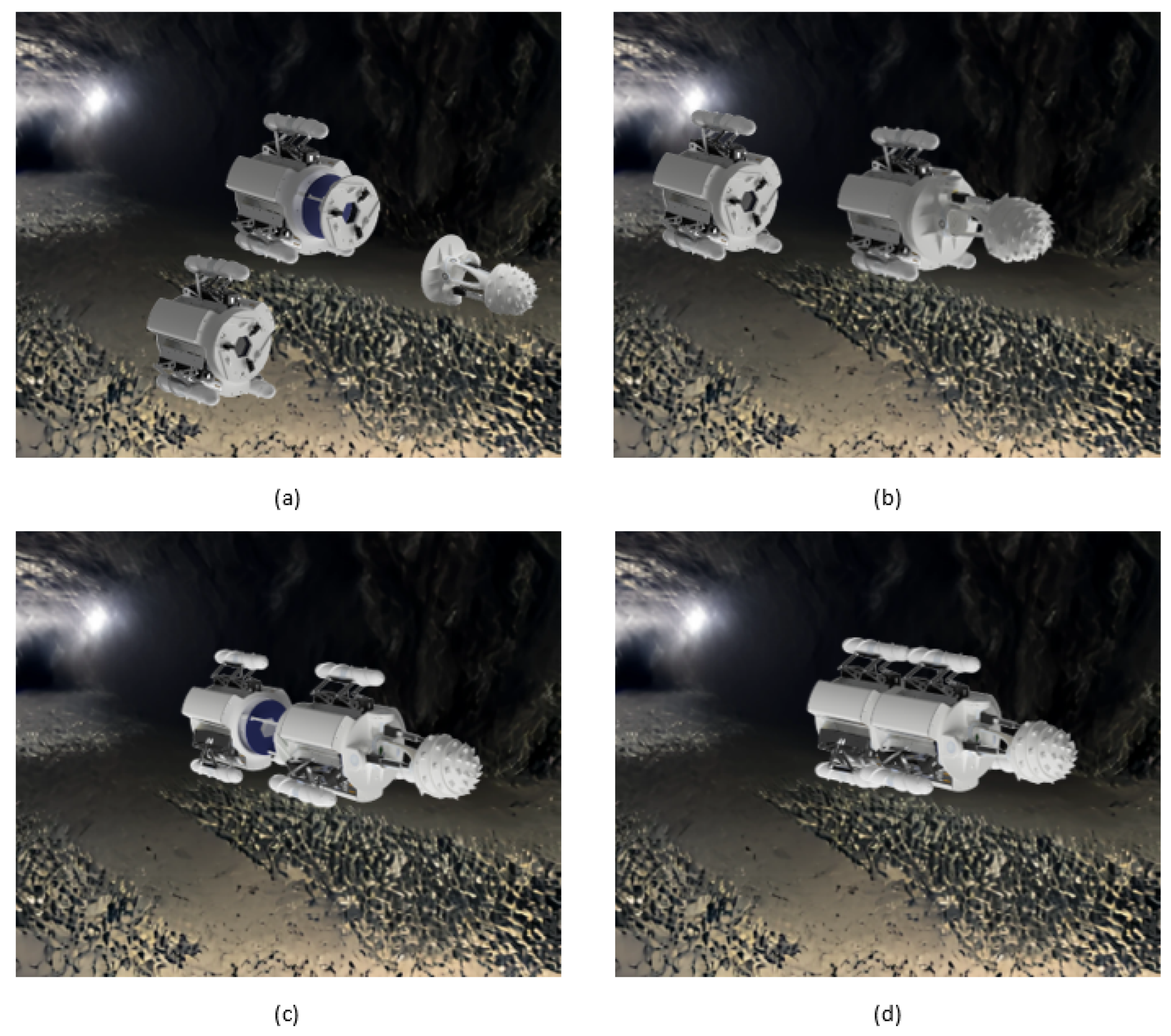
Figure 1 shows a situation where robotic modules perform this function during a mining task: the robot changes its cutting head according to the material it is extracting, attaches special sensing devices, and connects several modules to increase its strength or replaces failed modules with new ones. This adaptability allows on-the-job reconfiguration.
The concepts of reconfiguration, self-assembly, and self-repair have been extensively explored in recent years with several works [
7,
8,
9,
10] compiling the most relevant developments. Within the broad spectrum of reconfigurable modular robots, this study focuses on reconfigurable, mobile platforms that can operate in rough environments. These platforms interact with the environment independently and can generate larger and more complex robotic systems by connecting several modules through various docking mechanisms. In this group, we found platforms like Milibot [
11]: a set of semi-autonomous, tracked mobile platforms is arranged into a train configuration to cross relatively large obstacles. The platforms are equipped with a set of coupler pins that allow the modules to engage and disengage under computer control. Another remarkable development is the S-bots [
12,
13,
14] system: autonomous, tracked-and-wheeled, reconfigurable mobile robots. The reconfiguration is achieved either by a robotic gripper or a manipulator arm integrated into the structure of the robot to allows for rigid and semi-flexible connections. The rigid gripper permits the lifting of another module while the arm allows for flexible connections where the modules retain relative freedom of movement with respect to each other. Other examples include the modular JL-I,2 platforms [
15,
16]. In this case, the first version of the system was composed of a series of tracked mobile robots equipped with a cone-shaped connector and a parallel manipulator that resulted in an active spherical joint that allowed the modules to rotate in three dimensions. Therefore, different 3D configurations can be achieved. For the second version, the docking interface was modified to include a gripper, allowing the modules to achieve basic manipulation as well as locomotion. Additional developments like AMOEBA-I and the different versions of the platform [
17] present a reconfigurable, modular, tracked robot structure capable of docking from all sides, and generating chain, triangular and row formations depending on the specific terrain condition. The docking interface is based on a set of links that connect to other tracks and can change position and orientation with respect to the central structure.
Previous research efforts have indeed made significant progress, but certain limitations persist concerning the configurability and adaptability of self-assembly systems, particularly in unstructured environments. Commonly used docking mechanisms, such as latches, mechanical links, and rigid grippers face vulnerabilities when confronted with uneven terrain, limited visibility, and unpredictable objects.
To address these challenges and align with the project’s long-term vision, this study introduced a versatile and configurable modular robotic system with a novel docking mechanism. The system comprises robotic modules capable of self-assembly and reconfiguration during operation, along with manually assembled and self-assembled submodules that extend the resulting robotic systems’ functionalities. A significant innovation is the seamless integration of a compact, soft robotic arm into the robot structure. Unlike other reconfigurable platforms, our arm remains protected within the robot when not used. Additionally, integrating soft arms as coupling mechanisms enhances adaptability and performance during docking maneuvers, especially in unstructured environments. The soft robotic arm operates like a car crane during docking or undocking, effortlessly guiding itself to another module or submodule’s docking port, securing it in place, and then retracting to complete the process.
The article is organized as follows.
Section 2 provides a description of the modular robot platform with all the possible locomotion submodules as well as an integrated arm that acts as a coupling interface. In
Section 3, we introduce different submodules that can be coupled to the modular robot to perform several tasks.
Section 4 solves the kinematics of the robotic platform and the singularities, and presents a workspace analysis for the leg mechanism. In
Section 5, we show different configurations of the robotic platform and carry out several locomotion tests and module reconfiguration to demonstrate the functionality of the elements that make up the robotic system. Finally,
Section 6 provides the conclusions and summarizes future developments.
2. Robotic Module Description
The presented robotic system is based on highly configurable modules capable of self-assembly and reconfiguration during operation. In our context, the term ”robotic modules” refers to mobile platforms that can operate independently, while submodules are considered add-ons that can be attached to the module to perform a specific task. The concept of self-assembly is the robot’s ability to form larger structures by connecting different modules or submodules during an operation without the need of human intervention. The concept of self-reconfigurability is related to the ability of the robot to reconfigure its control system automatically as larger structures are formed, i.e., introducing new capabilities into the system as modules or submodules are connected.
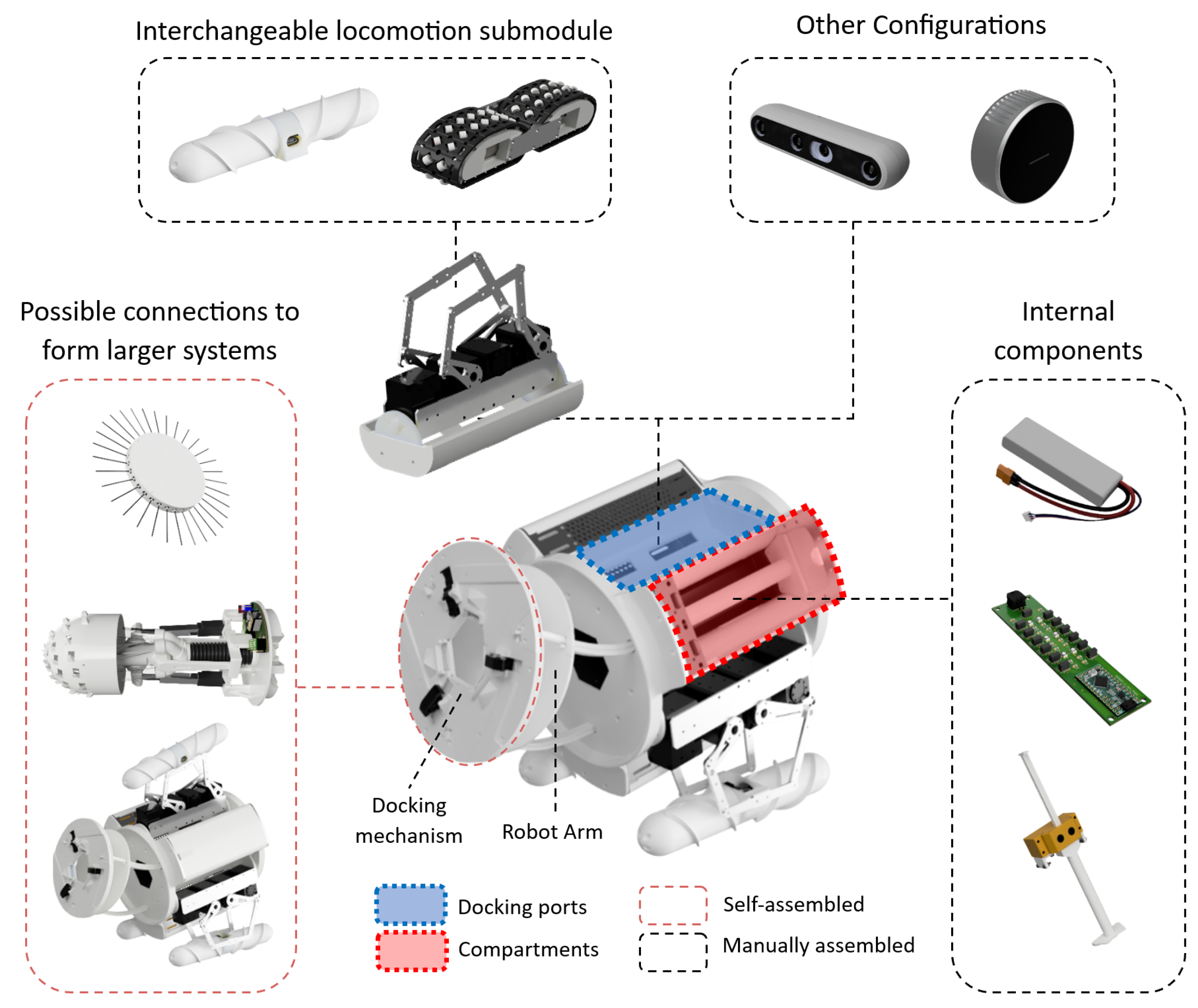
The main component of the system consists of robotic modules that are composed of a main structure with three compartments and three docking ports, as presented in
Figure 2. Electronic components, batteries, and other actuation systems are located in the compartments and in the robot’s internal structure. Interchangeable end effectors or additional sensors are assembled in docking ports depending on the task to be performed. To form larger and more complex structures, the module is equipped with a coupling mechanism based on a soft continuum arm with a mechanical coupling interface where the arm is integrated into the structure of the robot.
Modules can be powered by either an external power source or a 3S battery that can be installed in the robot. Inside the module, a power board made up of a set of voltage converters (12, 6, 5) is used to power the robot’s different electronic components and motors. A 12 V line is used to supply energy to both the locomotion submodules’ motors and the legs’ servomotors. The 6 V powers the robot coupling mechanism, and the 5 V supplies energy to different sensors and microcontrollers. The technical specifications of the robot module are presented in
Table 1.
The design of the robot module is inspired by a mine-ready robotic system developed within the framework of the project, where each mining robot module is 1.5 m long, approximately 1 m in diameter, and weighs approximately 500 kg. The robot module presented here serves as a scaled-down version of the larger mine-ready robotic system and its primary purpose is to study the concepts of modularity, self-assembly, and reconfiguration during operation to provide insight into different configuration possibilities and emphasizing the importance of adaptability and versatility.
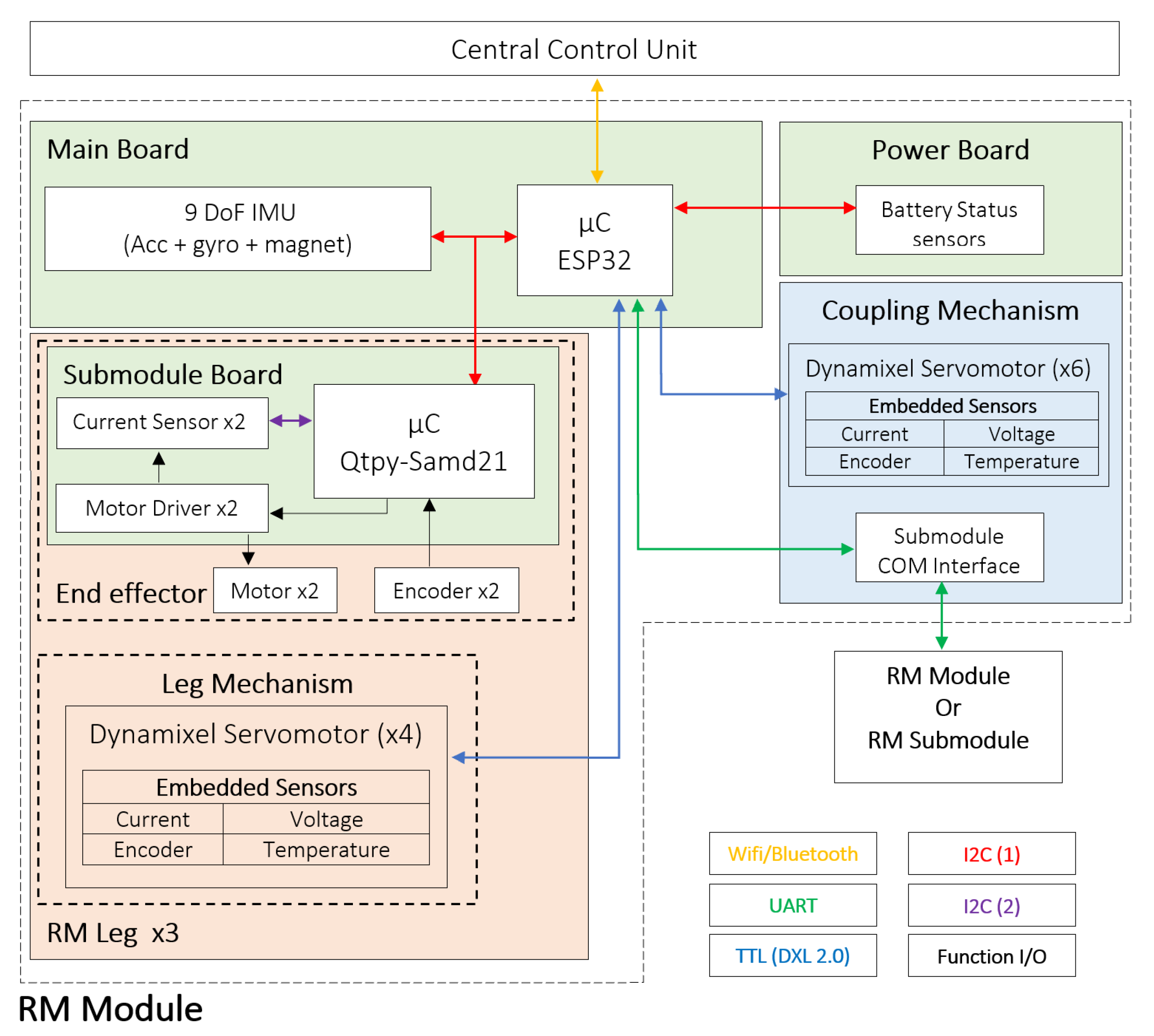
The connection of the robot components and the communication protocols used are shown in
Figure 3, where each component is classified according to its location and functionality. To communicate the different components of the robot, the following protocols were defined:
Two low-level I2C-based protocols with a cyclic redundancy check (CRC) were implemented. The first I2C protocol communicated both the ESP32 and QtPy boards, as well as the different sensors of the robot. The second one collected sensor data from the locomotion submodule, maintaining the needed modularity to easily change the locomotion submodules.
One half-duplex universal asynchronous receiver–transmitter (UART) (TTL daisy-chained bus) using the manufacture’s protocol Dynamixel protocol 2.0 was used to enable the ESP32 to communicate with the leg-and-coupling mechanism servomotors.
One custom UART protocol was implemented to communicate with other robotic modules or submodules when they were attached via the robot coupling mechanism.
A transparent wireless protocol using WiFi or Bluetooth to link the ESP32 to the central control unit (CCU).
Figure 3.
ROBOMINER communication protocol diagram. The green squares represent the PCB boards of the robotic module. The different colored arrows show the different protocols implemented for both intra- and intercommunication.
Figure 3.
ROBOMINER communication protocol diagram. The green squares represent the PCB boards of the robotic module. The different colored arrows show the different protocols implemented for both intra- and intercommunication.
To monitor the state of the different modules and to teleoperate the system, a graphical user interface (GUI) based on Qt (
Figure 4) was designed. The GUI was organized in a set of windows and tabs where the information of the robot components was presented in a comprehensive manner. Every time a robot established a connection with the CCU, a new tab appeared in the main window of the GUI, allowing the user to decide which robot module to monitor or teleoperate.
2.1. Locomotion Submodules
To provide the modules with the ability to navigate in unstructured environments, different locomotion submodules were developed. These were easily interchangeable due to a standard mounting interface, and each had a different operation principle.
2.1.1. Archimedean Screw
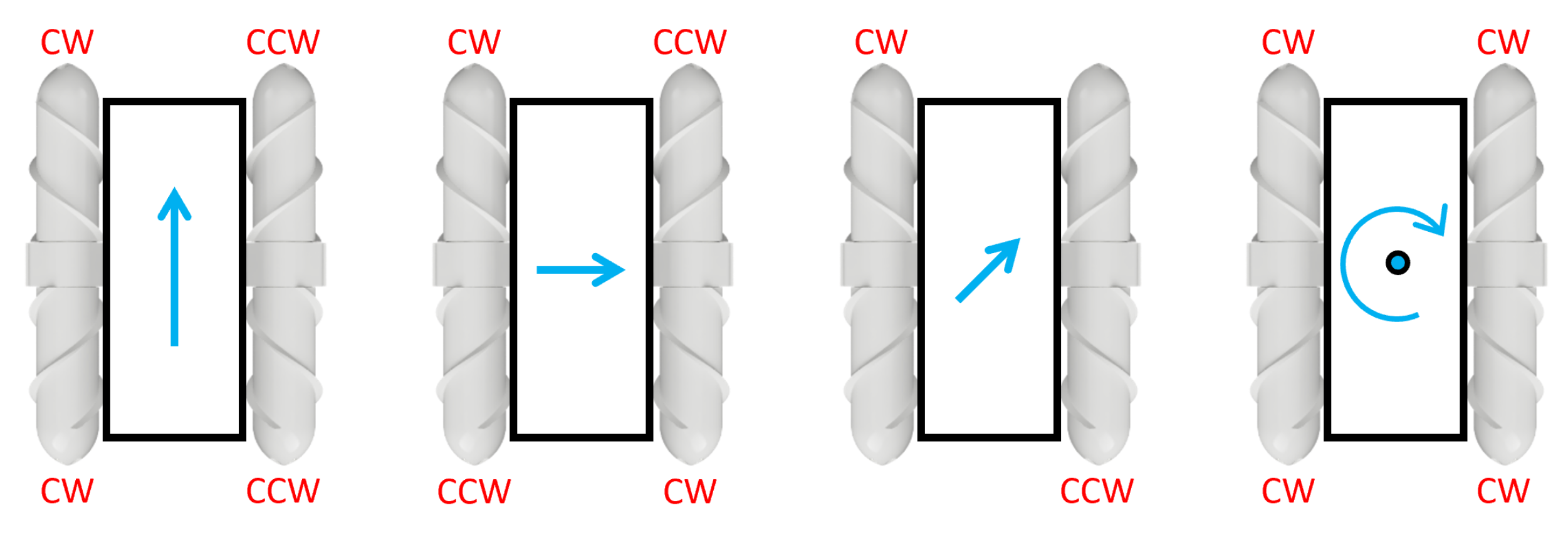
The Archimedean screw locomotion submodule consists of a set of two helical screw-like structures that are strategically designed with interlocking threads, providing a continuous surface for propulsion. When activated, the screw rotates, causing the helical threads to grip the terrain or the surrounding medium. By generating rotational motion, the screw threads created forward or backward movement, propelling the robot through its environment [
18]. To achieve omnidirectionality, two screw submodules were arranged in a mirror configuration, as shown in
Figure 5.
One of the key advantages of this submodule is its adaptability to different surfaces and terrains [
19]. The Archimedean screw mechanism excels in environments such as loose soil, sandy terrain, or even under water where conventional wheels or legs may struggle to maintain traction. The continuous contact of the screw threads with the ground enables effective propulsion and minimizes slippage, enhancing the robot’s mobility. Furthermore, it offers inherent resistance to obstacles encountered during navigation. The screw’s helical structure allows it to navigate over small barriers, debris, or uneven terrain, reducing the risk of getting stuck or immobilized.
2.1.2. Omnidirectional Continuous Track
The continuous track locomotion submodule consisted of a continuous track loop made of flexible 3D-printed material with a set of passive urethane wheels embedded in the track loop oriented at a 45° angle with respect to the vertical line. The track loop was carefully designed to ensure great traction, durability, and flexibility, allowing it to conform to the terrain and maintain constant contact for optimal propulsion.
The submodule was composed of two independently actuated omnidirectional tracks with the passive wheels oriented in opposite directions. When activated, the locomotion submodule propelled the robot by rotating the continuous track loop. The robot achieved omnidirectional movement with two submodules in a mirror configuration (
Figure 6) by selectively controlling different sections of the track loops.
2.2. Robot Arm
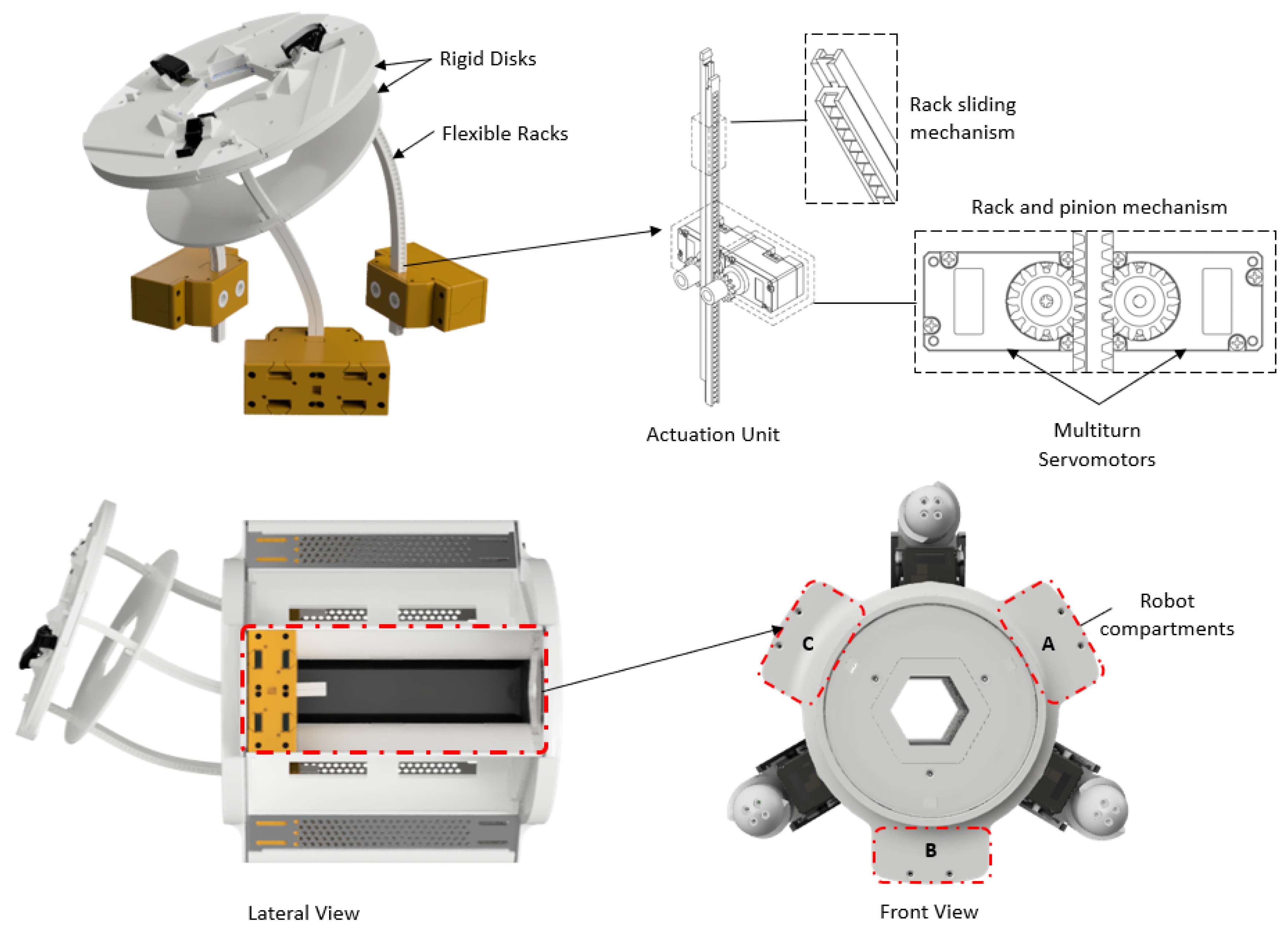
The robot arm consisted of a soft continuum arm with a mechanical interface embedded at the tip of the arm that acts as a module/submodule coupling interface. The arm was integrated into the module structure and used as a mechanical interface to join two robotic modules or submodules to create more robust or complex systems to perform different tasks. The prototype, presented in
Figure 7 was composed of two sections with a set of flexible racks and rigid disks where the endpoints of the rack were attached. The movement of each section was based on the displacement of the racks following the rack and pinion mechanism [
20], which gave the arm a high mass-pulling force ability. The extension, retraction, and bending of the racks resulted in the control of three degrees of freedom (DoFs) per section: two for bending and one for extension. Therefore, having two sections, we obtained the final configuration of the arm that gave 5 DoFs for the arm tip position (
x,
y,
z) and orientation (pitch, roll) and an additional DoF to control the bending inflection point.
The mechanical interface (
Figure 8a) comprises a set of three equally spaced claws driven by a mechanical system composed of a subactuated 4-bar mechanism and a worm-crown gear powered by a small DC motor. The 4-bar mechanism is designed to achieve a wide enveloping movement that helps catch the passive port. Here, the rotational movement of the crown gear translated into the linear motion of the base of the claw that caused the docking maneuver. The maneuver took place when the coupling head was close to a passive coupling port (
Figure 8b) following a procedure similar to the one in a car crane. Here the arm reached the docking port, secured the robotic module/submodule, and subsequently retracted, pulling the arm back into the robotic module. Finally, the three magnetic connectors housed inside the arm’s tip allowed communication between the modules or module/submodule as well as power-sharing. The remaining pin served as a security check that indicated that the physical connection was correct in all three connectors.
3. Robotic Submodules
Because of the coupling mechanism, robotic modules can be configured to form complex systems by connecting to neighboring modules or to specific robotic submodules that perform different tasks. In the following section, we present two robotic submodules that give the system the capability to perform different tasks, like mining or mapping.
3.1. Mining Submodule
Considering that the future robotic miner needs to be able to optimize its path inside the new mine architecture to reach the ore, the correct cutting technology is critical. Roadheaders, traditionally used in tunneling and underground excavation, have demonstrated their efficiency and precision in cutting through rock and other geological formations [
21]. By integrating a roadheader into a mining robot, we can envision a versatile and autonomous machine capable of navigating complex underground environments while simultaneously performing accurate and controlled cutting operations. For this reason, we developed a scaled version of a traditional roadheader-cutting head design. The prototype is actuated with a set of linear actuators and an extrinsic universal joint that allows the movement of a cutting head driven by a DC motor (
Figure 9a). The actuation mechanism (
Figure 9b) generates a circular cutting pattern that covers the area of the robotic miner, allowing it to advance into the mine. Additionally, a suction system is integrated into the submodule to absorb the material to process it later while it passes through the robotic modules, as shown in
Figure 9c.
3.2. Sensing Submodule
In underground environments where cameras and LiDAR struggle due to low light conditions and dust interference, the preference shifts towards contact-based sensing technology. These advanced systems rely on direct physical contact with objects and surfaces to gather crucial information about the surroundings. By enhancing and expanding the capabilities of contact-based sensing, we can overcome the limitations posed by the absence of light and dust in subterranean environments.
Whiskers are a class of tactile sensors that have recently gained popularity. Inspired by mammals, whiskers display tremendous potential in a variety of applications [
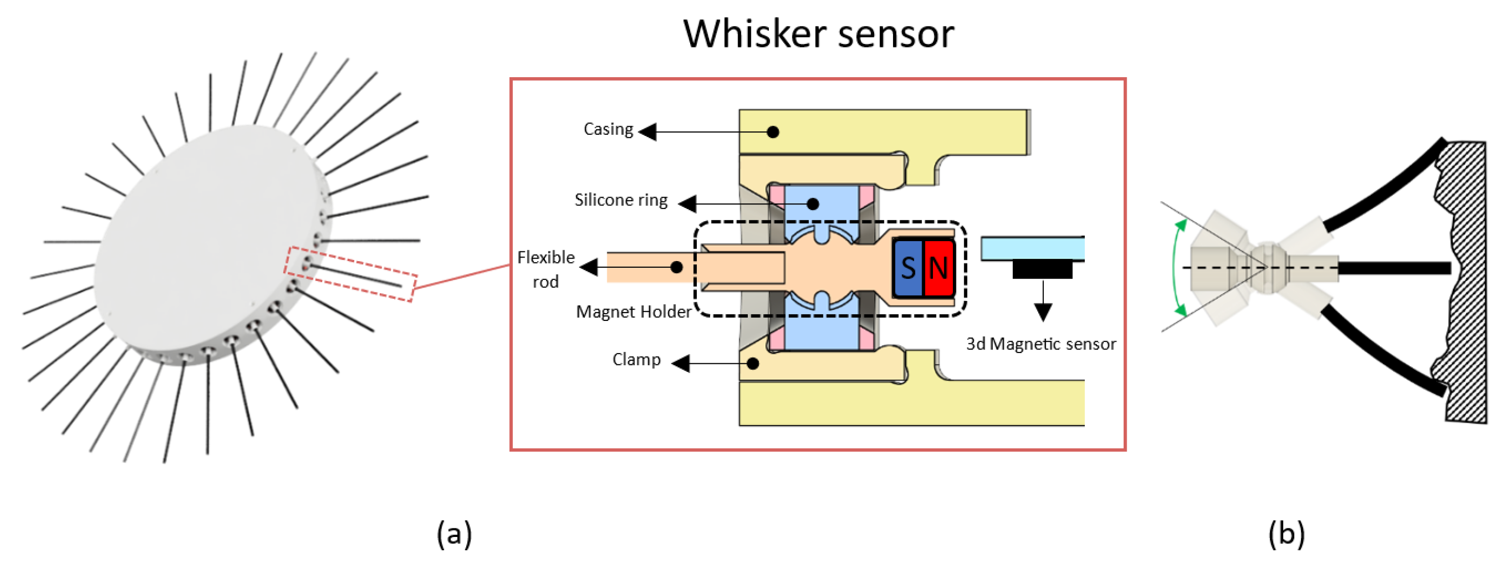
22] including robotics. Based on this, we developed a sensing head submodule composed of a circular array of 3D magnetic sensors that translates the magnetic field intensity of a magnet, housed inside a 3D-printed structure resembling a joystick, into a position in space. The magnet holder, presented in
Figure 10a is held in place by two silicone rings and allows the structure to move like a joystick (
Figure 10b). At the other end of the magnet holder, a rod made of flexible material serves as the point of contact between the geometry that is to be captured and the sensor. When the rod comes in contact with an object, it starts to bend and move the magnet holder. The movement of the magnet is then captured by the sensor, which maps the change of the 3D magnetic field into the resulting bending angle. Finally, considering a model where the rod is rigid and knowing the length of the rod, a point cloud can be generated from the measurements of the sensor array.
4. Robotic Module Kinematics
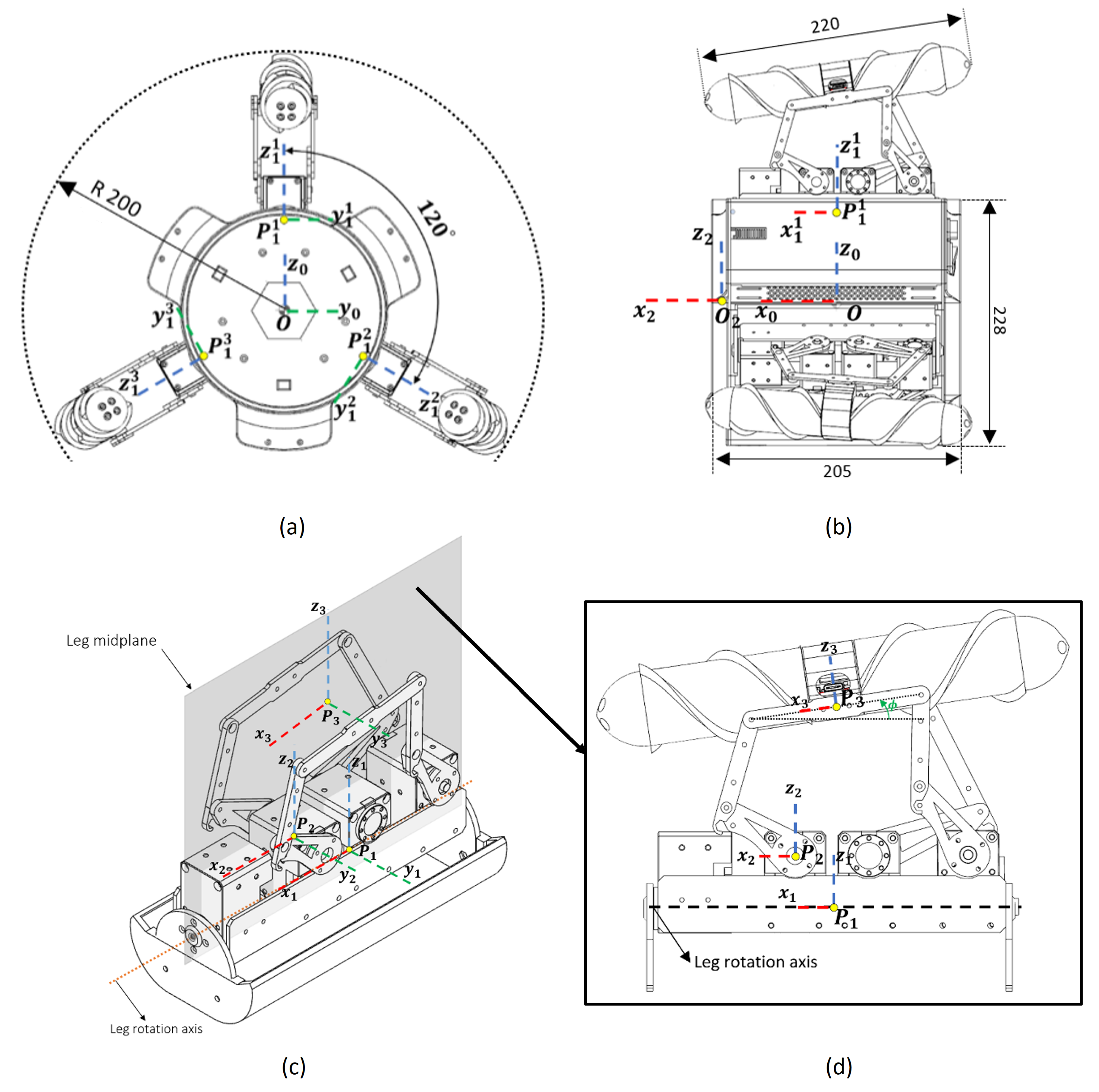
Establishing reference frames is crucial for effective control of the robot since we used these references and the distances between them to determine its position and orientation and main components. Starting with the base reference, we established the robot reference in its geometric center as shown in
Figure 11a,b, where the positive
x-axis is normal to the front face of the robot. Then, the pivotal point of the leg axis was considered another point of reference, and it was repeated for each leg. The leg reference was considered so that the transformation from the base frame to the leg would be the most convenient. It should be noted that legs 1 and 3 are rotated ±120
with respect to the
x-axis of the base reference. Then, for the reference frame of the leg mechanism (
Figure 11c) the point resulting from the intersection of the mid-plane of the leg and the second motor axis was considered. This point was set as the origin of the kinematic analysis of the leg mechanism. Finally, the end effector reference frame was set at its center, by which the
x-axis coincided with the midpoint of the horizontal bar of the mechanism. The frame’s position measured from the robot datum is presented in
Table 2.
The robot leg mechanism has 4 DoFs where the motor connected to the docking port acts as a revolute joint that rotates the entire leg. The planar mechanism gives the remaining 3 DoFs, allowing control of the position and orientation of the end effector as shown in
Figure 11d. The reference frames for the leg mechanism are shown in
Table 3.
4.1. Mechanism Description
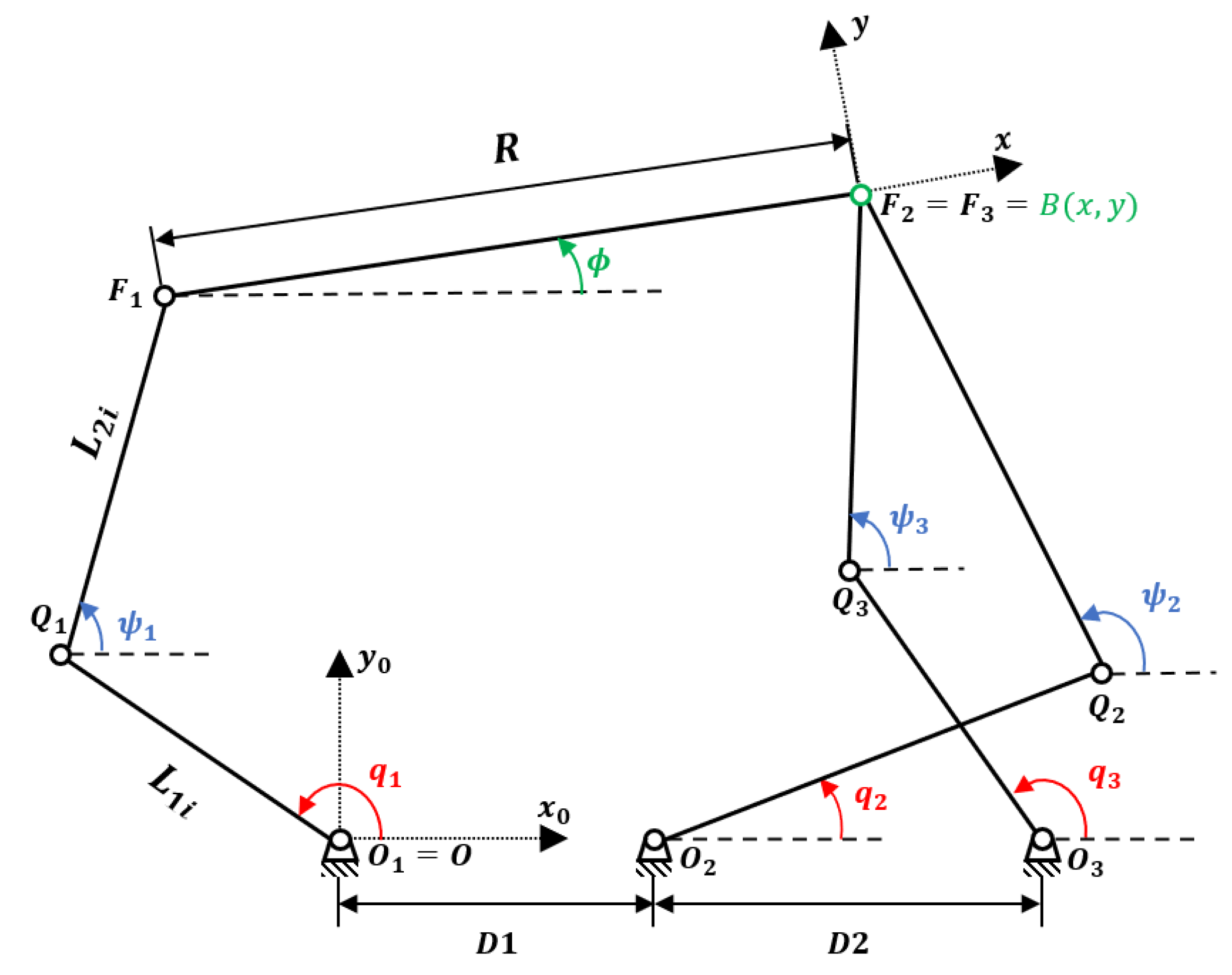
For the following mechanism, we designed a structure in which the position of point B of the platform (shown in
Figure 12) was controlled by a 5-bar planar link (
), and the orientation (
) by a 4-bar link (
). Similar to [
23], the linear displacements and orientation of the presented structure were decoupled: actuators 2 and 3 (
and
) controlled the position of the end effector, and actuator 1 (
) controlled its orientation. In addition, the mechanism can rotate on the
x-axis, providing the robot with an additional DoF, which was controlled by the front motor.
As shown in
Figure 12, the axis
is along the vector
and is defined this way for convenience. The lengths of the
and
links are indicated by
and
, respectively. The dimension of the platform
is indicated by
R. The positions of the base axes
along the
and
axes are denoted (
,
), with
. Let us consider the geometric models of the manipulator. From the previous description, one can find the loop–closure equations:
where:
Developing Equation (
1) we obtained the following relationships:
Here,
represents the expression of the vector
in the base frame. For
i = 2 and 3,
, and
.
Rearranging Equation (
5) and squaring both sides, we obtain the following system.
4.2. Forward Kinematics
The forward kinematics of the robot allows us to determine the position of the end effector given the motor inputs. Due to the decoupling properties of the robot leg, the forward geometric model of the mechanism can be solved in two main steps:
Developing Equations (7) and (8) and factorizing with respect to
x and
y, yields
where, for
i = 2,3:
From Equations (9) and (10), we obtained the following relation for the horizontal coordinate of
B:
Introducing it into Equation (
9) led to, for
:
where
Solving Equation (
15) led to the expression for the vertical coordinate of
B.
in which the sign ± stands for two possible assembly modes of the system composed of links 1 and 2. In our case, we considered the “+” assembly mode according to the mechanism design. Introducing Equation (
19) into Equation (
14) gave us the position of point
B. Next, introducing Equations (14) and (19) into Equation (
6) led to the following:
where
Using the following relationships:
Equation (
20) can be rewritten as the following polynomial equation:
Thus, the solutions of Equation (
25) can be found as follows.
Therefore, given the motor input, the orientation of the end effector was determined by solving Equation (
27) in which the sign ± stood for the two possible modes of mechanism assembly. In our case, the “−” solution was the one used since the mechanism was used in this assembly mode.
4.3. Inverse Kinematics
On the other hand, determining the inverse kinematics model, we determined the motor angles that gave a known position and orientation of the end effector.
Rewriting Equations (6)–(8) in a more general way, we obtained
Developing (28) and factoring with respect to
and
:
where
Using the relations in Equation (
24), Equation (
29) became
Thus, by solving Equation (
33), we obtained the following expressions:
Therefore, for a given position and orientation of the end effector, the motor input was determined by solving Equation (
35). There were two possible solutions that changed consideration of how the mechanism’s joints were working. On this occasion, the joints
considered the “−” solution, while
considered the “+” solution.
4.4. Singularity Analysis and Mechanism Workspace
To determine the singular points of the mechanism, we first need to define an implicit function
of the set of actuated joints
and the Cartesian coordinates
x of the end effector. In this case looking at Equations (6)–(8) we wrote the relationship between the input and output coordinates as
Differentiating (36) with respect to time led to the relationship between the input and output speeds.
where
is the platform twist;
is the vector of the articular velocities; and
A and
E are Jacobian matrices of n x n, of which the expressions are
Singularities occur in configurations where A or E become singular. For this to happen, there are three types that have different physical interpretations and appear when the following conditions are met:
Type 1 singularity (
) appears when the segments
and
are located on the same line (
Figure 13a)
Type 2 singularity () appears in two separate cases:
when the segments
and
are collinear (
Figure 13b).
when the segments
and
are located on the same line (
Figure 13c).
Type 3 singularities () are based on the construction of the mechanism. On this occasion, no special singularity was detected based on the mechanism shape.
Figure 13.
Singular configurations of the robot leg mechanism. (a) Singularity type 1. (b) Singularity type 2a. (c) Singularity type 2b.
Figure 13.
Singular configurations of the robot leg mechanism. (a) Singularity type 1. (b) Singularity type 2a. (c) Singularity type 2b.
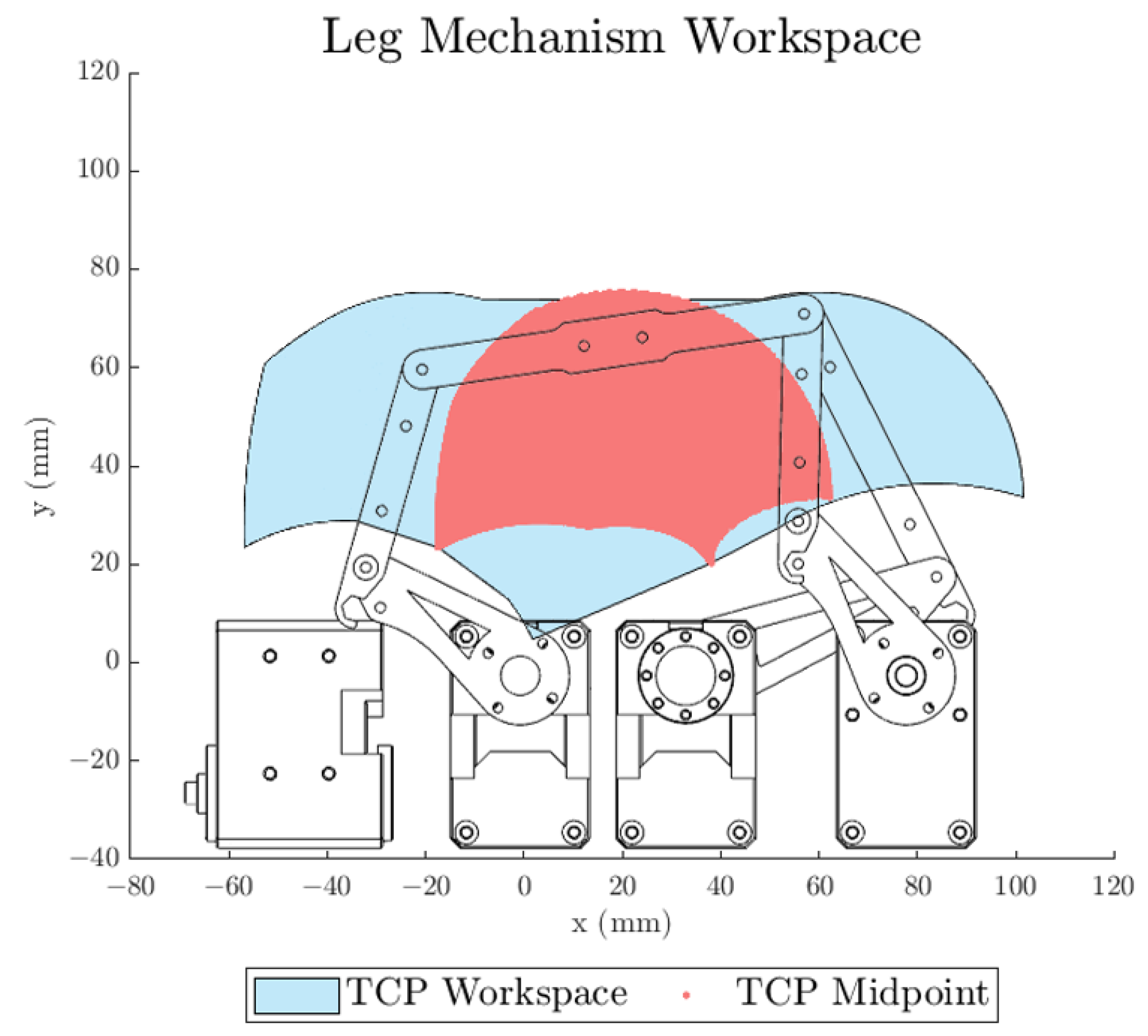
Therefore, considering the range for each actuator for the given mechanism (
) and excluding singular positions, the mechanism workspace was obtained in
Figure 14. It should be noted that the mechanism workspace was reduced once a locomotion submodule was installed since the geometry of the submodule reduced the maneuverability of the mechanism.
5. Experiments
To assess the abilities of the robotic system, we fabricated two modules with different locomotion configurations along with prototypes of the mining and sensing submodules. The materials chosen for the main structure of the robotic modules included aluminum laser-cut profiles, ABS, and ASA 3D-printed parts. The leg mechanism was also constructed from aluminum. Additionally, the majority of components in the locomotion, mining, and sensing submodules were 3D-printed using ABS.
For the soft robotic arm, the racks were made from a flexible 3D-print material called TPU95A while the rigid disks are made from ABS. These material selections were specifically tailored to suit the size and requirements of the demonstrator. However, it is important to emphasize that for a mine-ready platform, careful consideration and adaptation of materials was necessary. The materials had to withstand the increased stresses and harsh conditions associated with larger sizes and heavier loads in a practical mining environment.
5.1. Module Configurability Test
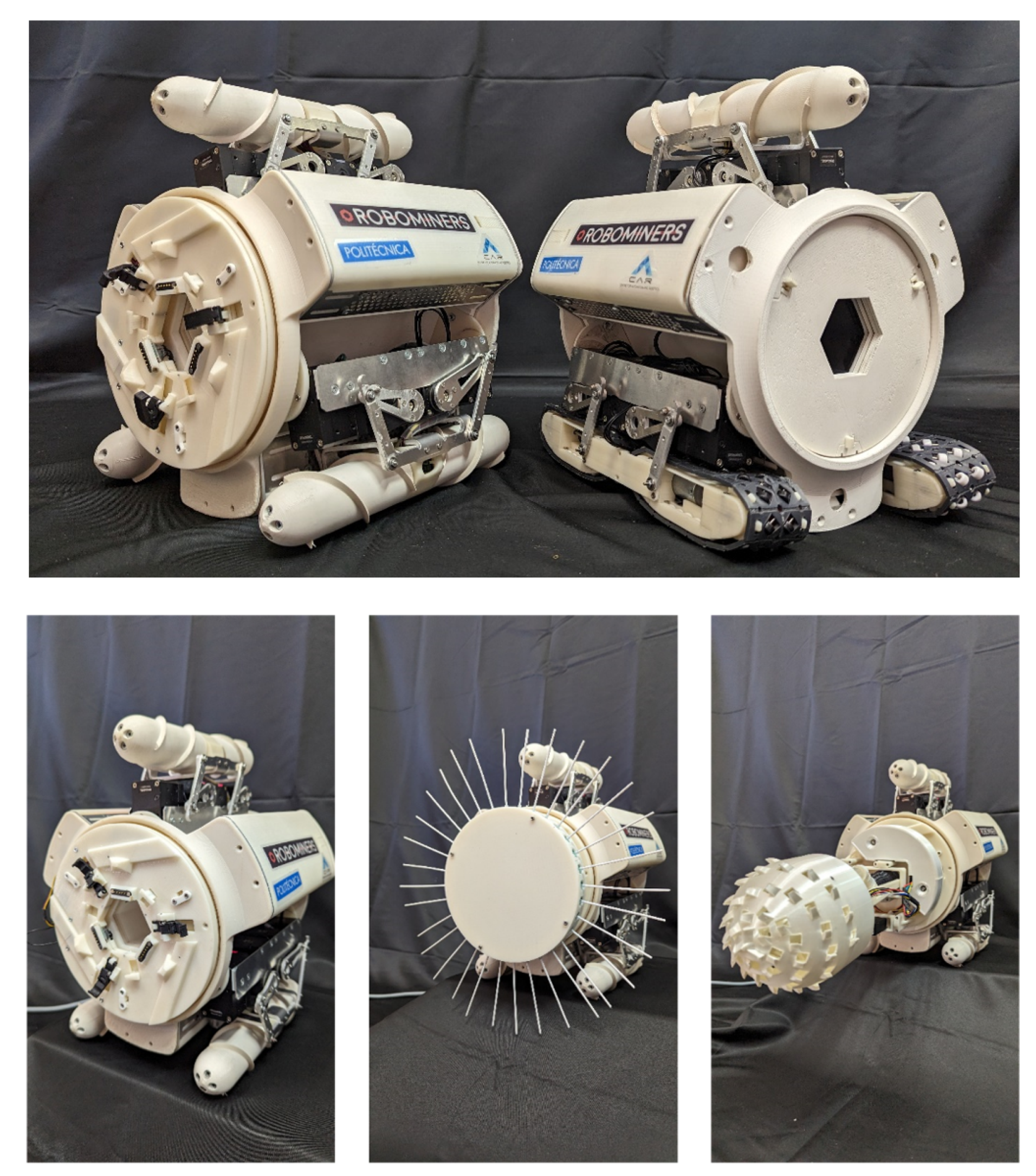
Several tests were carried out to try different robotic-module setups and achievable robotic systems. Since the module can be configured with different components based on the task to be performed, we present in
Figure 15 a set of achievable configurations that could have been adopted by the robotic module.
In standby mode, the robotic modules consume an average of 0.7A. However, during operation with a configuration featuring 3 robot legs, their power demand can increase to 4A.
For the robotic system, two docking experiments were performed where the soft continuum arm coupled two robotic modules together and attached a tool to the robot front.
Figure 16 presents a sequence of both experiments. The first experiment consisted of demonstrating the car crane principle by connecting two robotic modules. First, the module arm was teleoperated into the rear port of the second robot module. When the arm docking interface was near the passive interface, a command was sent to the robot to perform the closing maneuver of the claws and profiles into the passive port. Upon completion of this maneuver, the module read the safety check-pin status of the magnetic connectors to ensure that the module was properly connected. Once the module had been secured, the racks were retracted to complete the docking maneuver. Inversely, for the undocking process, a command was first sent to the robot to undock the claws and profiles to the open position. Once this had been completed, the robot sent a message to the CCU confirming that the docking mechanism was in the open position. Next, the robot was commanded to retract the arm into the robot structure to protect it from the environment until a new docking maneuver with a module or submodule is required. While performing the coupling maneuver, the current draw of the module increased up to 1.5A as the second module was pulled into the robot module.
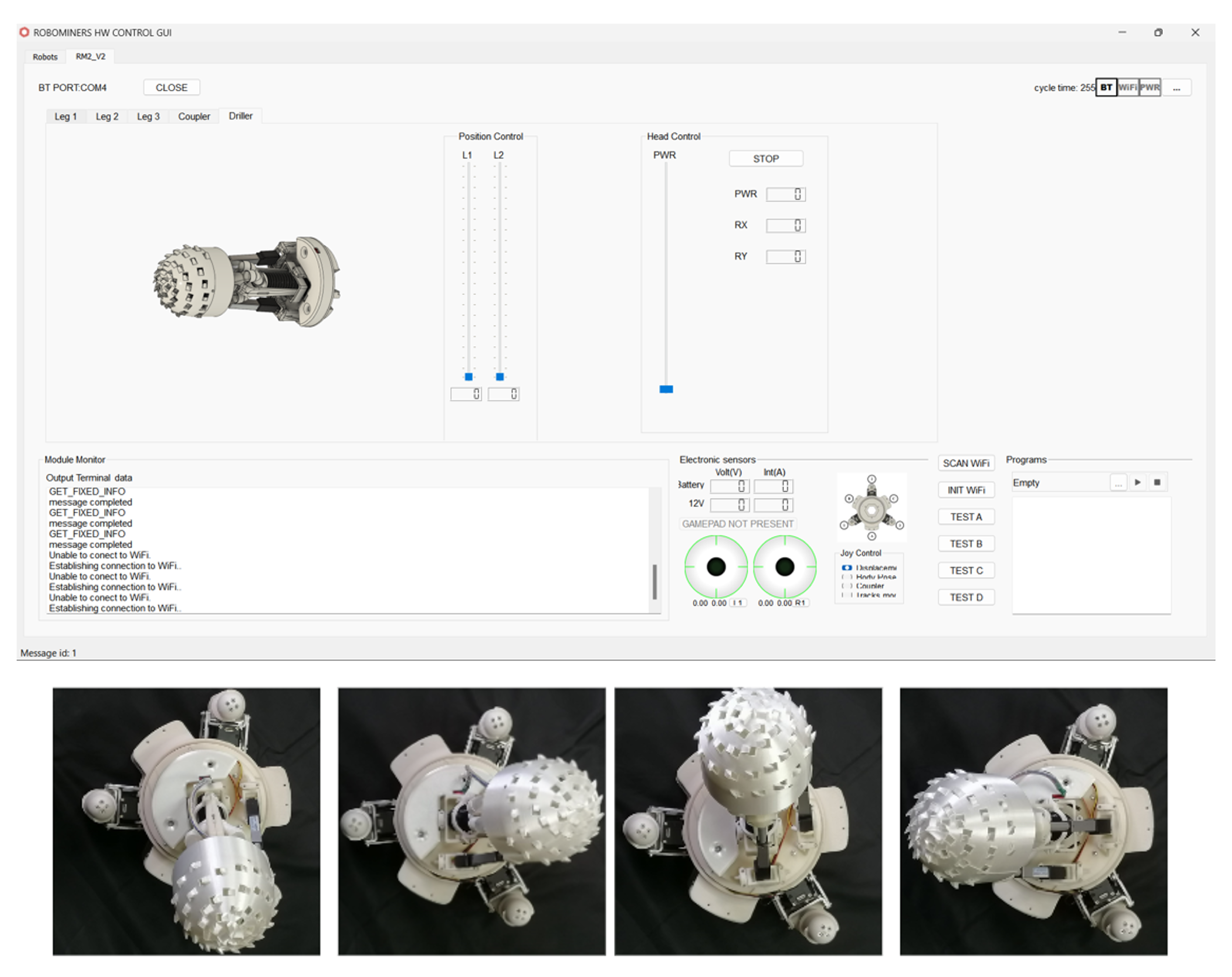
For the second experiment, a pre-installed mining submodule was attached to the robotic arm and a retraction of the arm to lift the mining submodule into the robotic system was performed. After the submodule was secured and connected to the robotic module, a new window appeared (
Figure 17) in the Qt GUI that allowed the user to control the mining submodule by commanding the linear actuator angles as well as the cutting head speed. The current draw of the resulting system during operation ranged between 3 and 4.5A, with the highest value occurring during the execution of mining tasks.
Video S1 from the Supplementary Material shows the coupling maneuvers as well as a mining demo for a robotic system composed of two robotic modules and the mining submodule.
5.2. Locomotion Tests
To validate the design of the locomotion submodules, different tests were carried out. Omnidirectional movement and navigation capabilities of the robotic modules were tested in different scenarios. These included locomotion on inclined and irregular terrain.
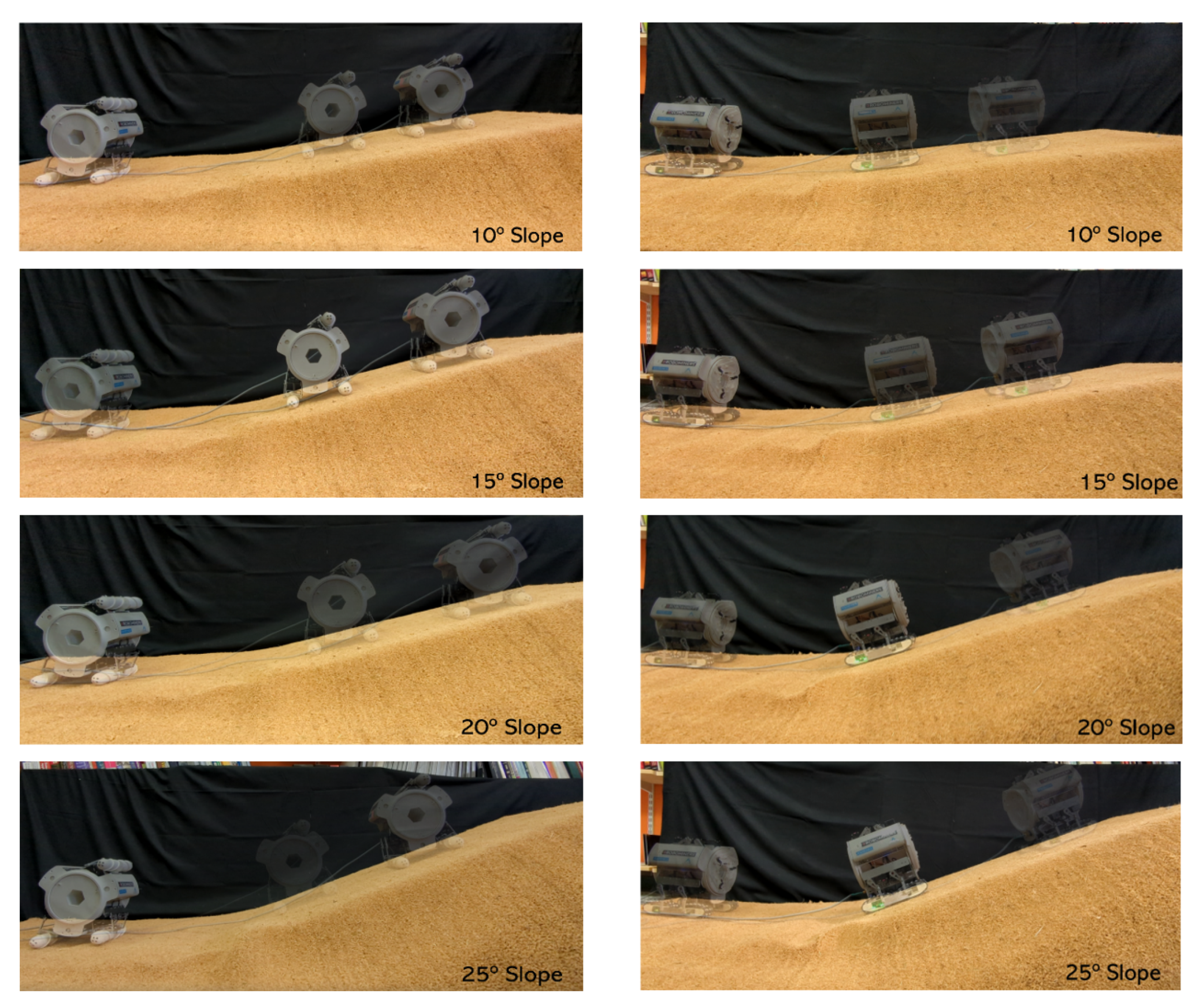
The inclined-terrain tests were carried out by varying the slope of a surface where the robot had to climb. Slopes between 10–25
were considered for both robot configurations where the screw module navigated in a lateral fashion while the track wheel advanced straight. The maximum peak current observed was 2A for the Archimedean screw configuration for the 25° slope.
Figure 18 shows the sequence for both configurations at different inclinations, where the two modules successfully climbed the four slopes.
To showcase the locomotion capabilities of the module in irregular terrain, various mock-up configurations of unstructured terrain were created and tested. The objective was to assess the ability of the teleoperated module to navigate and exhibit omnidirectional movement. Both screw and track configurations successfully traversed the environment, demonstrating remarkable adaptability and omnidirectional movement within the surroundings. Detailed experiments and visual documentation of these tests can be found in
Video S1, available in the
Supplementary Materials section.
During the test elaboration, it was observed that the screw structure design exhibited limitations in performing straight movements on smooth terrain. This limitation arose from slippage of the surface and the discontinuity of the screw thread towards the tip of the structure. Similarly, the tracks were unable to execute lateral motion effectively in rough terrain due to improper contact of the passive wheels, which prevented successful maneuvers. However, these issues did not impede the modules’ ability to navigate across varied terrain. Future design iterations will address these challenges to enhance the modules’ maneuverability in all conditions.
6. Conclusions
This research paper presented the development of a demonstration modular robotic system to investigate the characteristics of modularity and self-assembly. The article detailed the mechanical and electrical design of the system components, kinematic modeling of the robotic module, and successful tests conducted to assess configurability and locomotion. Through the exploration of various configuration possibilities, the study highlighted the significance of adaptability and versatility in mining operations. This work is a foundational step towards the long-term goal of developing compact autonomous agents capable of self-assembly and completing mining tasks.
The concept of a highly configurable platform was demonstrated by presenting different configurations, with successful coupling maneuvers between robotic modules and submodules using the soft continuum arm. Furthermore, a mining task performed by a system composed of two modules and a mining submodule showcased the potential of applying robotic systems in mining operations.
The locomotion tests yielded satisfactory results for both screw-powered and track-powered submodules. These modules displayed the ability to climb slopes of up to 25° without issue and demonstrated adaptability over rough and irregular terrains. However, some non-critical issues were detected during operation on smooth and irregular terrains for screws and tracks, respectively. On smooth terrain, screws exhibited reduced maneuverability due to limitations in the straight locomotion mode. For tracks, irregular contact of the passive wheels with the terrain affected correct execution of the lateral locomotion mode when traversing irregular terrain. These issues will be addressed in future optimizations of locomotion submodules.
Although the materials and components used in the scaled-down model may not be directly applicable to a real mining system, the underlying concepts validated in this platform can easily be adapted without significant issue. This study serves as proof of concept for a larger, mine-ready robot.
In developing a full-scale mining robotic system, adjustments were essential. The materials needed to be reinforced to withstand the greater stresses and challenges of heavy-duty mining operations. Additionally, the components had to be scaled up to take into account the extreme conditions the platform may encounter within the mine. Moreover, the communication protocols had to be tailored to suit the specific conditions of the mining environment. By addressing these factors, adapting the proven concepts to a real mining system became feasible and practical.
Future research work will focus on enhancing the module’s ability to operate in real-world scenarios. This includes developing autonomous self-assembly and collaboration algorithms that enable the robot to adapt to diverse environments. The autonomous self-assembly procedure is currently in development and is based on a computer-vision algorithm where a camera submodule integrated into the module structure captures the position and orientation of a marker located on the coupling interface of a second module or submodule. Then, using the inverse kinematics model, the arm is guided to the captured point. In addition, a set of 3D magnetic Hall-effect sensors assists the arm in aligning the docking interfaces to successfully perform the docking maneuver.
On the other hand, efforts are underway to develop gait methods that allow the robot to adapt to its environment when a locomotion submodule is damaged or encounters an obstacle, thus ensuring robust performance under challenging conditions.
Regarding control strategies, a meta-control model is being developed to improve the robustness and fault tolerance of the robot modules. These strategies, as well as other coordination and configuration algorithms, will be tested on a simulated version of robot modules. Most of these developments are intended to be transferred to a mine-capable robot in real-world scenarios.
Author Contributions
Conceptualization, V.G. and M.H.; Formal analysis, V.G., M.H. and E.A.; Funding acquisition, C.R.; Investigation, V.G. and M.H.; Methodology, V.G.; Project administration, C.R.; Resources, R.S. and C.R.; Software, M.H.; Supervision, M.H.; Validation, V.G. and E.A.; Writing—original draft, V.G.; Writing—review & editing, M.H., E.A., R.S. and C.R. All authors have read and agreed to the published version of the manuscript.
Funding
This research was funded by the European Commission’s Horizon 2020 research and innovation program (ROBOMINERS, grant no. 820971) and has received funding from the RoboCity2030-DIH-CM, Centro de Innovación Digital de Robótica de Madrid, S2018/NMT-4331, funded by Programas de Actividades I+D en la Comunidad de Madrid and co-financed by EU Structural Funds.
Acknowledgments
We would like to thank Alvaro Palmero, Daniel Bajo Collados, Oscar Rudek, and Maurizio Lo truglio for their collaboration in the project.
Conflicts of Interest
The authors declare no conflict of interest. Funding institutions had no role in the design of the study; in the collection, analyses, or interpretation of data; in the writing of the manuscript; or in the decision to publish the results.
References
- Rogers, W.P.; Kahraman, M.M.; Drews, F.A.; Powell, K.; Haight, J.M.; Wang, Y.; Baxla, K.; Sobalkar, M. Automation in the mining industry: Review of technology, systems, human factors, and political risk. Min. Metall. Explor. 2019, 36, 607–631. [Google Scholar] [CrossRef]
- Zhang, K.; Kang, L.; Chen, X.; He, M.; Zhu, C.; Li, D. A Review of Intelligent Unmanned Mining Current Situation and Development Trend. Energies 2022, 15, 513. [Google Scholar] [CrossRef]
- Bołoz, L.; Biały, W. Automation and Robotization of Underground Mining in Poland. Appl. Sci. 2020, 10, 7221. [Google Scholar] [CrossRef]
- Wang, M.; Bao, J.; Yuan, X.; Yin, Y.; Khalid, S. Research Status and Development Trend of Unmanned Driving Technology in Coal Mine Transportation. Energies 2022, 15, 9133. [Google Scholar] [CrossRef]
- Shahmoradi, J.; Talebi, E.; Roghanchi, P.; Hassanalian, M. A Comprehensive Review of Applications of Drone Technology in the Mining Industry. Drones 2020, 4, 34. [Google Scholar] [CrossRef]
- Sayed, M.E.; Roberts, J.O.; Donaldson, K.; Mahon, S.T.; Iqbal, F.; Li, B.; Franco Aixela, S.; Mastorakis, G.; Jonasson, E.T.; Nemitz, M.P.; et al. Modular Robots for Enabling Operations in Unstructured Extreme Environments. Adv. Intell. Syst. 2022, 4, 2000227. [Google Scholar] [CrossRef]
- Brunete, A.; Ranganath, A.; Segovia, S.; de Frutos, J.P.; Hernando, M.; Gambao, E. Current trends in reconfigurable modular robots design. Int. J. Adv. Robot. Syst. 2017, 14. [Google Scholar] [CrossRef]
- Dokuyucu, H.I.; Özmen, N.G. Achievements and future directions in self-reconfigurable modular robotic systems. J. Field Robot. 2023, 40, 701–746. [Google Scholar] [CrossRef]
- Liu, J.; Zhang, X.; Hao, G. Survey on research and development of reconfigurable modular robots. Adv. Mech. Eng. 2016, 8. [Google Scholar] [CrossRef]
- Saab, W.; Racioppo, P.; Ben-Tzvi, P. A review of coupling mechanism designs for modular reconfigurable robots. Robotica 2019, 37, 378–403. [Google Scholar] [CrossRef]
- Brown, H.; Vande Weghe, J.; Bererton, C.; Khosla, P. Millibot trains for enhanced mobility. IEEE/ASME Trans. Mechatronics 2002, 7, 452–461. [Google Scholar] [CrossRef]
- Dorigo, M.; Trianni, V.; Sahin, E.; Groß, R.; Labella, T.H.; Baldassarre, G.; Nolfi, S.; Mondada, F.; Deneubourg, J.L.; Floreano, D.; et al. Evolving Self-Organizing Behaviors for a Swarm-bot. Auton. Robot. 2004, 17, 223–245. [Google Scholar] [CrossRef]
- Gross, R.; Bonani, M.; Mondada, F.; Dorigo, M. Autonomous Self-Assembly in Swarm-Bots. IEEE Trans. Robot. 2006, 22, 1115–1130. [Google Scholar] [CrossRef]
- Dorigo, M.; Tuci, E.; Trianni, V.; Groß, R.; Nouyan, S.; Ampatzis, C.; Labella, T.H.; O’Grady, R.; Bonani, M.; Mondada, F. SWARM-BOT: Design and Implementation of Colonies of Self-Assembling Robots. In Computational Intelligence: Principles and Practice; Yen, G.Y., Fogel, D.B., Eds.; IEEE Computational Intelligence Society: New York, NY, USA, 2006; pp. 103–136. [Google Scholar]
- Guanghua, Z.; Zhicheng, D.; Wei, W. Realization of a Modular Reconfigurable Robot for Rough Terrain. In Proceedings of the 2006 International Conference on Mechatronics and Automation, Luoyang, China, 25–28 June 2006; pp. 289–294. [Google Scholar] [CrossRef]
- Wang, W.; Yu, W.; Zhang, H. JL-2: A Mobile Multi-robot System with Docking and Manipulating Capabilities. Int. J. Adv. Robot. Syst. 2010, 7, 9. [Google Scholar] [CrossRef]
- Li, B.; Ma, S.; Liu, J.; Wang, M.; Liu, T.; Wang, Y. AMOEBA-I: A Shape-Shifting Modular Robot for Urban Search and Rescue. Adv. Robot. 2009, 23, 1057–1083. [Google Scholar] [CrossRef]
- Nagaoka, K.; Otsuki, M.; Kubota, T.; Tanaka, S. Terramechanics-based propulsive characteristics of mobile robot driven by Archimedean screw mechanism on soft soil. In Proceedings of the 2010 IEEE/RSJ International Conference on Intelligent Robots and Systems, Taipei, Taiwan, 18–22 October 2010; pp. 4946–4951. [Google Scholar] [CrossRef]
- Richter, F.; Gavrilov, P.V.; Lam, H.M.; Degani, A.; Yip, M.C. ARCSnake: Reconfigurable Snakelike Robot With Archimedean Screw Propulsion for Multidomain Mobility. IEEE Trans. Robot. 2022, 38, 797–809. [Google Scholar] [CrossRef]
- Hernando, M.; Bajo, D.; Gomez, V.; Aguado, E.; Rossi, C. Sistema mecáNico de Actuación para un Brazo robóTico Flexible. Spanish Patent No. ES2907801, 18 October 2022. Available online: https://es.espacenet.com/publicationDetails/biblio?FT=D&date=20220426&DB=&locale=es_ES&CC=ES&NR=2907801A1&KC=A1&ND=4 (accessed on 6 July 2023).
- Jun, M.; Jian-gang, L.; Wei-kang, L.; Zhi-yong, H. Kinematics analysis and simulation of profiling memory cutting for tunnel robot in complex environment. Procedia Earth Planet. Sci. 2009, 1, 1411–1417. [Google Scholar] [CrossRef][Green Version]
- Sayegh, M.A.; Daraghma, H.; Mekid, S.; Bashmal, S. Review of Recent Bio-Inspired Design and Manufacturing of Whisker Tactile Sensors. Sensors 2022, 22, 2705. [Google Scholar] [CrossRef] [PubMed]
- Arakelian, V.; Briot, S.; Jatsun, S.; Jatsun, A. A New 3-DoF Planar Parallel Manipulator with Unlimited Rotation Capability. In Proceedings of the 13th World Congress in Mechanism and Machine Science, Guanajuato, Mexico, 19–23 June 2011. [Google Scholar]
Figure 1.
Concept of a set of highly configurable modular robotic miners that work together to perform a complex task. (a) Modular prototypes and tools are deployed in the mine environment. (b) The first robotic module assembles a cutting head on its front. (c) The second module is at the back of the first module and begins to assemble to create a larger robotic structure. (d) Finally, the resulting structure, made up of two modular robots and a robotic submodule, is assembled to perform a complex task: mining.
Figure 2.
Robotic module description. Each robotic module comprises three compartments and three docking ports. The docking ports serve the purpose of configuring diverse locomotion submodules or additional sensors like cameras or LiDAR. Within the compartments, various internal components are housed. The robot arm allows the autonomous coupling of different modules and robotic submodules to form more complex systems.
Figure 4.
ROBOMINER Qt GUI. The interface is composed of a set of windows and tabs that present information regarding battery status (if connected), Dynamixel sensors, WiFi/Bluetooth connectivity, input, and output messages for debugging purposes, as well as teleoperation and robot configuration features.
Figure 5.
Motor sense combinations to achieve omnidirectional motion for the Archimedean screw locomotion submodule (CW ≡ clockwise rotation, CCW ≡ counter-clockwise rotation).
Figure 5.
Motor sense combinations to achieve omnidirectional motion for the Archimedean screw locomotion submodule (CW ≡ clockwise rotation, CCW ≡ counter-clockwise rotation).
Figure 6.
Motor sense combinations to achieve omnidirectional motion for the continuous track locomotion submodule.
Figure 6.
Motor sense combinations to achieve omnidirectional motion for the continuous track locomotion submodule.
Figure 7.
ROBOMINER soft robotic arm description. The arm is integrated into the structure of the modular platform, where a set of servomotors are responsible for actuating each pair of flexible racks following the rack-and-pinion mechanism.
Figure 7.
ROBOMINER soft robotic arm description. The arm is integrated into the structure of the modular platform, where a set of servomotors are responsible for actuating each pair of flexible racks following the rack-and-pinion mechanism.
Figure 8.
Coupling interfaces for the modular robot. (a) process of coupling between the active and passive interfaces where a set of equally distributed claws and profiles secures a passive interface through different docking ports. (b) Isometric view of the passive coupling interface with detailed views of the docking port and the enveloping movement of the claw while a docking maneuver is carried out.
Figure 9.
Cutting submodule description. (a) Isometric view with component description. (b) Model representation of the submodule kinematics. (c) Detailed view of the submodule suction system when connected to a modular robot.
Figure 9.
Cutting submodule description. (a) Isometric view with component description. (b) Model representation of the submodule kinematics. (c) Detailed view of the submodule suction system when connected to a modular robot.
Figure 10.
Sensing submodule description. (a) The submodule is composed of a circular array of 32 whiskers comprising a magnet holder that has a flexible rod on one end and a magnet on the other. (b) The movement of the rod is translated to the magnet which changes the magnetic field measured by the sensor, resulting in the mapping of the point of contact of the flexible rod with a surface.
Figure 11.
Robotic module references frames and transformations to solve the kinematic problem. (a) Robot module front view. (b) Robot module lateral view. (c) Leg mechanism isometric view. (d) Midplane view of the leg mechanism equipped with a screw locomotion submodule as an end effector. All measurements are in millimeters.
Figure 12.
Closed planar kinematic chain analysis of the robot leg. The model represents the simplified version of the leg midplane view (
Figure 11d), where
coincides with
.
Figure 12.
Closed planar kinematic chain analysis of the robot leg. The model represents the simplified version of the leg midplane view (
Figure 11d), where
coincides with
.
Figure 14.
Leg mechanism-resulting workspace. The blue region represents the workspace of the mechanism for the final link represented as a horizontal line in the stored configuration. The red area represents the midpoint position of the final link where the interchangeable end effectors are mounted.
Figure 15.
Different possible configurations for ROBOMINER platform. Different locomotion submodules can be easily installed into the robot structure. In addition, other submodules for sensing and mining can be installed when the module has integrated a soft robotic arm.
Figure 15.
Different possible configurations for ROBOMINER platform. Different locomotion submodules can be easily installed into the robot structure. In addition, other submodules for sensing and mining can be installed when the module has integrated a soft robotic arm.
Figure 16.
Robotic system reconfiguration test.
Figure 16.
Robotic system reconfiguration test.
Figure 17.
Mining head connectivity and circular pattern test.
Figure 17.
Mining head connectivity and circular pattern test.
Figure 18.
Locomotion capabilities of the robotic module on inclined surfaces. Left, a robotic module with screws; right, the module with omnidirectional tracks.
Figure 18.
Locomotion capabilities of the robotic module on inclined surfaces. Left, a robotic module with screws; right, the module with omnidirectional tracks.
Table 1.
Technical specifications of robotic modules.
Table 1.
Technical specifications of robotic modules.
| Specifications | Values |
|---|
| Power | 12–15 V, 300 W (max) | Battery: 3S 2200 mAh 70C |
| Computing | QTPy-SAMD21—locomotion submodules and robot submodules
ESP32-DevKitC V4—Main Board |
| Communication | I2C,TTL—internal
UART—module intercommunication
WiFi/Bluetooth—external |
| Sensors | Motor Current (INA 219)
Battery Status (MCP3424, INA219)
IMU 9-DoF (BNO055)
Magnetic Encoders
Dynamixel sensors (temp, volt, current, encoder) |
| Actuators | DC Motors—Locomotion Submodules and Coupling mechanism
Dynamixel Servomotors (XM430-W350-T)—Robot Legs
Dynamixel Servomotors (XL330-M288-T)—Coupling Mechanism |
| Mass | 3.90 kg (module with 3 legs) | 0.8 kg (robot structure) |
| Dimensions | Length: 22 cm | Diameter: 30–40 cm |
Table 2.
Robominer module reference frames.
Table 2.
Robominer module reference frames.
| Reference Frame | Symbol | Description | {x,y,z} with Respect to Base Reference [mm] |
|---|
| Robot Base Datum | O | RM Geometric Center | {0,0,0} |
| Robot Arm Datum | | Robot Arm Base | {101.87,0,0} |
| Robot Leg | | Leg 1 axis | {0,0,74.653} |
| Leg 2 axis | {0,64.95,−37.85} |
| Leg 3 axis | {0,−64.95,−37.85} |
Table 3.
Leg mechanism reference frame.
Table 3.
Leg mechanism reference frame.
| Reference Frame | Symbol | Description | {x,y,z} with Respect to Leg Axis [mm] |
|---|
| Leg mechanism datum | | Motor_x1 | {16.97,0,24.25} |
| End effector | | End effector joint | See kinematics (Section 4.1) |
| Disclaimer/Publisher’s Note: The statements, opinions and data contained in all publications are solely those of the individual author(s) and contributor(s) and not of MDPI and/or the editor(s). MDPI and/or the editor(s) disclaim responsibility for any injury to people or property resulting from any ideas, methods, instructions or products referred to in the content. |
© 2023 by the authors. Licensee MDPI, Basel, Switzerland. This article is an open access article distributed under the terms and conditions of the Creative Commons Attribution (CC BY) license (https://creativecommons.org/licenses/by/4.0/).
