Article

Influence of the Slot Fillet and Vane Root Fillet on the Turbine Vane Endwall Cooling Performance

1
School Power and Energy, Northwestern Polytechnical University, Xi’an 710072, China
2
Yangtze River Delta Research Institute of NPU, Northwestern Polytechnical University, Taicang 215400, China
3
Shaanxi Key Laboratory of Thermal Sciences in Aero-Engine System, Northwestern Polytechnical University, Xi’an 710129, China
4
NPU-KAI International Joint Laboratory of Advanced Aero-Engine Thermal Structure, Northwestern Polytechnical University, Xi’an 710129, China
5
AECC Hunan Aviation Powerplant Research Institute, Zhuzhou 412002, China
*
Author to whom correspondence should be addressed.
Machines 2023, 11(7), 729; https://doi.org/10.3390/machines11070729
Submission received: 21 May 2023 / Revised: 3 July 2023 / Accepted: 6 July 2023 / Published: 10 July 2023
(This article belongs to the Section Turbomachinery)

Abstract

:
Due to machining techniques and dust deposition, gas turbine upstream slots and vane roots are always filleted, significantly affecting the cooling performance of the endwall. The effects of upstream slot fillet and vane root fillet on the cooling performance of the gas turbine endwall were investigated by solving the three-dimensional Reynolds-averaged Navier–Stokes (RANS) equations with the shear stress transport (SST) k–ω turbulence model. The results indicate that the velocity distribution of the slot coolant is effectively changed by introducing the upstream slot fillets. Among the four cases, the largest adiabatic cooling effectiveness was obtained for the case with two similar fillets, with a 42% increase in effective cooling area compared to the traditional slot. At MFR = 0.75%, the horseshoe vortex is weakened by the introduction of the vane fillet with a small radius, with a 53% increase in effective cooling area compared to the baseline. However, the vane fillet with a large radius makes the boundary layer flow separately prematurely, decreasing the cooling performance. The lateral coverage of the coolant jet from the filmhole embedded in the vane root fillet is greatly enhanced by increasing the vane root fillet radius. However, the streamwise coverage is decreased and the thermodynamic loss is increased.

1. Introduction

The turbine inlet temperature (TIT) is gradually increasing due to the pursuit of higher levels of thermal efficiency and output power. As a result, TIT is now beyond the thermal limit of state-of-the-art superalloy. Furthermore, to reduce NOx emissions, a design with more uniform temperature distribution at the combustor outlet is supplied, increasing the endwall thermal load. Therefore, the aerodynamics and thermal performance of the endwall is of great significance and must be investigated.
Many researchers have investigated the influence of endwall secondary flow [1]. According to Wang et al. [2], the velocity of airflow is reduced near the leading edge (LE) of the blade. Therefore, a horseshoe vortex is generated and its downstream branches produce strong convection. Furthermore, close to the endwall, the secondary flow is greatly affected by a strong three-dimensional flow separation [3]. As summarized by Goldstein et al. [4], horseshoe vortex, passage vortex, and corner vortex all have a significant contribution to the thermal performance of the endwall. For the gas turbine, the compressor delivers a relatively high-pressure coolant at the interface between the turbine and the combustor to provide sealing and prevent the mainstream ingestion [5]. As a result, a film cooling layer is created, which effectively protects the endwall surface covered by the coolant injection. Basically, the cooling jet from the upstream slot is greatly impacted by crossflow. Chowdhury et al. [6] investigated the influence of the mass flow ratio of the coolant to the mainstream utilizing pressure-sensitive coating technology (PSP). The results show that increasing the mass flow ratio can improve endwall cooling performance by preventing the development of the horseshoe vortex.
It has been discovered that the upstream configurations significantly affect aerodynamic and thermal performance. As far as endwall cooling is concerned, Gao et al. [7] claimed that when the blowing ratio increases, the magnitudes of adiabatic cooling effectiveness increase, but the growing slope decreases. Furthermore, it was found that the convergent slot increases the local adiabatic cooling effectiveness by improving the momentum of the coolant and limiting secondary flow. However, the heat transfer is also improved at the same time [8]. According to Du et al. [9], the adiabatic cooling effectiveness in the upstream region is greatly increased by the introduction of the contoured upstream slot. However, the normal upstream slot attains a relatively high adiabatic cooling effectiveness on the endwall. A misaligned slot was investigated experimentally by Kim et al. [10] and the findings show that the misalignment and the increased heat transfer caused by the flow mixing both lead to a higher thermal load. In addition, the negative slot incidence angle tends to have a great impact on the cooling performance of the endwall, as noted by Zhang et al. [11].
Many studies showed that the heat transfer performance of the endwall is also influenced by near-endwall structures [12]. It was found that a part of the coolant flow is swept across the endwall towards the corner of the suction side, intensifying the thermal load near the pressure side endwall [13]. Furthermore, the near-endwall ribs could effectively prevent the coolant from migrating from the pressure side to the suction side, improving the endwall adiabatic cooling effectiveness [14]. The non-axisymmetric endwall profiling was introduced by Rose [15] and it was proved to significantly reduce the pressure non-uniformity. Babu et al. [16] employed numerical methods to investigate the pressure-side boundary layer growth mechanism under the impact of a non-axisymmetric contouring endwall with purge flow and discovered that endwall contouring can provide highly efficient endwall protection. According to Mensch et al. [17], endwall contouring impeded the development of the passage vortex and decreased the mixing of the slot jet with the mainstream.
Many researchers have explored the potential of leading-edge contours in mitigating the adverse effect of secondary flow on turbine aerodynamic performance. In a low-speed cascade wind tunnel, Sauer et al. [18] conducted experiments on a turbine profile designed for highly loaded low-pressure turbines. The results revealed that the leading-edge bulb intensified the suction side branch of the horseshoe vortex while simultaneously weakening the passage vortex. This beneficial effect led to a significant reduction of 50% in endwall loss. Secondary flow appears to alter the heat transfer characteristics of the turbine endwall; therefore, the leading-edge contour draws the attention of researchers to endwall heat transfer. Shih and Lin [19] examined the influence of leading-edge airfoil fillet on flow and heat transfer numerically. Three fillet designs were simulated, and the findings revealed that fillets decrease heat transfer by more than 30% on the endwall.
There have been studies on vane leading-edge fillets, but due to manufacturing constraints, it is more likely for the fillets to be present around the perimeter of the vane root. To establish a foundation for endwall cooling design, the study of how the slot coolant affects the cooling performance of the endwall needs to be expanded. Considering engineering reality, to provide more effective protection for the endwall, this paper investigates the effects of slot fillet and root fillet on the cooling performance.

2. Computational Method and Validation

2.1. Geometrical Model

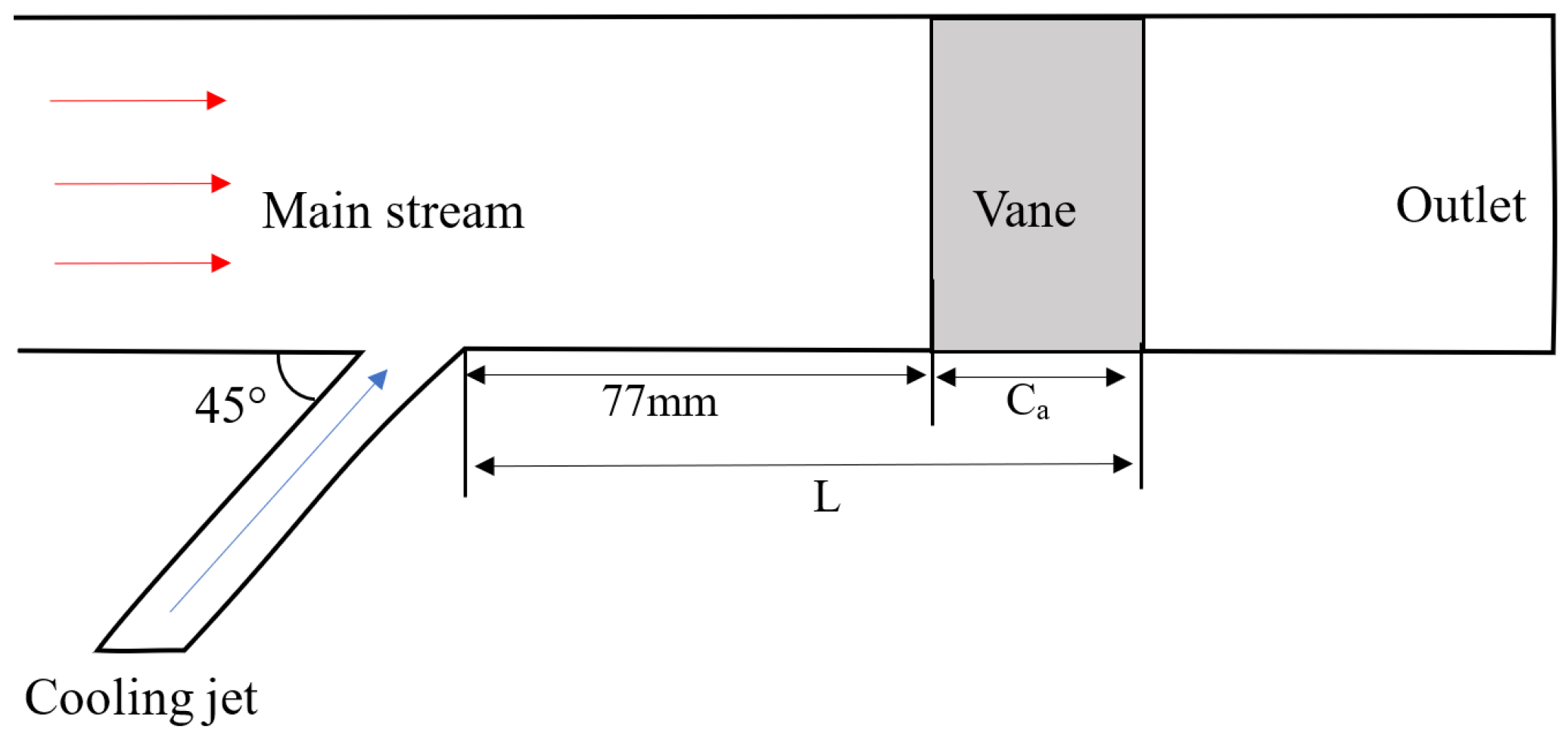
The vane profile studied in this paper is adopted from the experiments carried out by VirginiaTech University [20]. The linear cascade is obtained by stretching this vane profile. The slot located 77 mm upstream of the vane stagnation point has an injection angle of 45°. The coordinate system and top view of the model are depicted in Figure 1. L (370 mm) is defined as the distance between the trailing edge of the vane and the slot. The layout of the cooling structure and vane profile are shown in Figure 2. Moreover, to study the impact of the slot coolant more clearly, the film holes near the leading edge are removed. The boundary conditions and specific geometric parameters of the simulation are displayed in Table 1.

2.2. Numerical Method

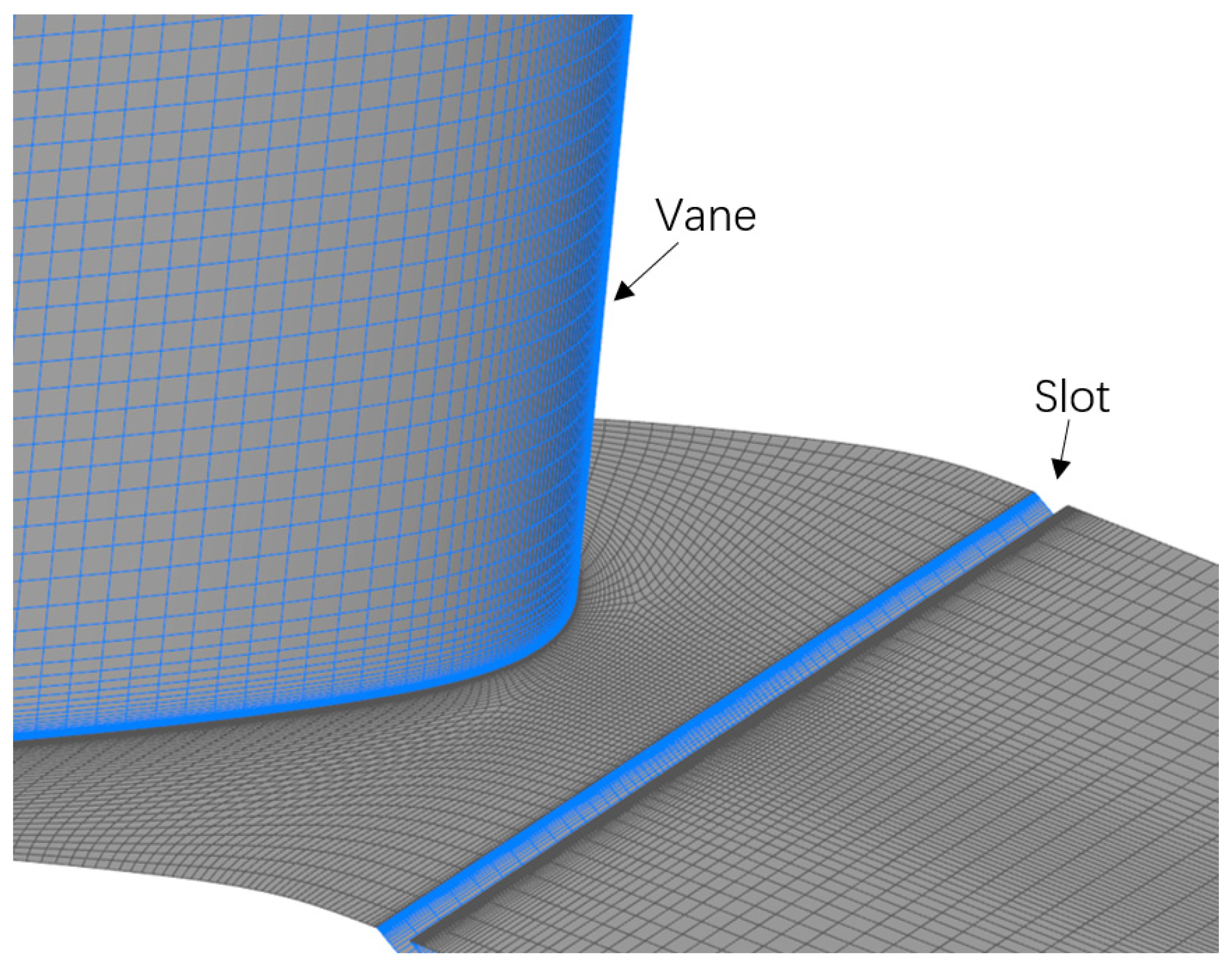
The ANSYS CFX was employed to solve the steady Reynolds-averaged Navier–Stokes (RANS) equations. Adiabatic non-slipping wall boundary and structured grids are adopted in the simulation. The gas in the simulation is set as ideal gas. To guarantee the orthogonality of the grids, the O-type grid is used for the regions around the vane surface. To accurately predict the wall heat transfer, the first cell thickness of the wall is refined to guarantee that the y+ values are smaller than 1.0. The intake section length is 0.75 times the length of the axial chord to generate a fully developed boundary layer flow. To prevent backflow, the outlet section’s length is 1.2 times the length of the axial chord length. The grids adopted in the computation are displayed in Figure 3. To achieve the specified mass flow ratio, a mass flow inlet with a 45° injection angle with respect to the endwall was installed at the slot entry.
The ratio of the film coolant mass flow rate to the mainstream mass flow (MFR) is defined as:
MFR = Mc/M
where Mc is the coolant mass flow and M is the mainstream mass flow. The fluid/fluid interface was employed at the slot exit to connect the slot injection and the passage’s mainstream. To produce fully developed turbulent inlet conditions corresponding with the experiment, an inlet imposed with the total pressure and total temperature is situated 0.75 axial chords upstream of the vane leading edge. During the steady-state simulation, the temperature difference between the mainstream and the coolant is kept at 40 K, which implies that the mainstream is set at 333.19 K and the coolant is set at 293.15 K.
The precision of the convective and viscous terms is of the second order. When the root mean square residuals of the governing equations reach a level of 10−5 and the flow imbalance rate for intake and output is less than 0.1%, it is determined that the steady computation is convergent.

2.3. Turbulence Model

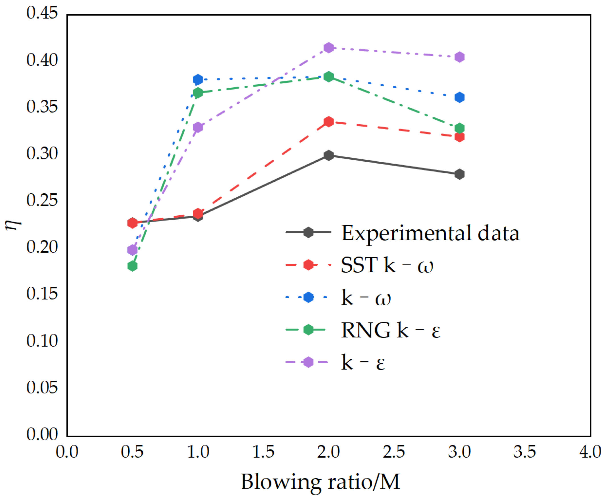
Using the same vane, references [9,21] both adopted the SST k–ω turbulence model. To guarantee the credibility of the predicted results, the numerical method was studied in ref. [21] by adopting four turbulence models (standard k–ε, RNG k–ε, standard k–ω, and SST k–ω turbulence models). For a blow ratio M of 0.3, Figure 4 presents a quantitative analysis of area-averaged (the region is shown in Figure 1) adiabatic cooling effectiveness for the experimental model. The blowing ratio (M) is defined as:
M = ρ c V c / ρ V
where ρ c and ρ are the densities of the coolant and mainstream fluid, respectively, and V c and V are the velocities of the coolant and the main flow, respectively. As shown in Figure 4, the standard k–ε model, standard k–ω model, and RNG k–ε model overestimate the adiabatic film cooling effectiveness at the higher blowing ratio. The above three turbulence models underestimate the adiabatic film cooling effectiveness at the lower blowing ratio. The SST k–ω turbulence model agrees well with the experimental results. Therefore, the SST k–ω turbulence model is utilized in the numerical simulation. In the experiment, the blowing ratio is used, but most current studies on purge flow adopt the mass flow ratio. Therefore, except for the numerical method validation part, MFR is used in the subsequent numerical studies.
The adiabatic cooling effectiveness definition ( η ) is given as:
η = T T a w / T T c
where T a w is the wall adiabatic temperature, T is mainstream temperature and T c is coolant temperature.

2.4. Grid Independence

In order to verify grid independence, 4.5 million, 7 million, 9 million, and 11 million grids are used. The meshes are refined at the same ratio along the x, y, z directions. In addition, the first layer grid cell of the wall is kept similar to maintain the proper y+. Table 2 provides the comparison of the results obtained by the four grids. The area of the leading edge is consistent with the area selected in the experiment shown in Figure 1. As the results show, the relative change rate of the average adiabatic cooling effectiveness is less than 0.5 percent when the grid number reaches 9 million. Therefore, the 9 million grids are selected in the numerical simulation.

3. Results

3.1. Influence of Slot Fillet

Due to the severe operating environment and the thermal loads that gas turbines withstand, upstream slot are susceptible to being rounded due to ablation and ash accumulation. Therefore, this section investigates the effect of slot fillet on endwall cooling performance. Figure 5 depicts the schematic of the slots with fillets in section A. The position of section A is shown in Figure 1. In Figure 5, R is 1% of the vane height, and W is set as 10 mm.
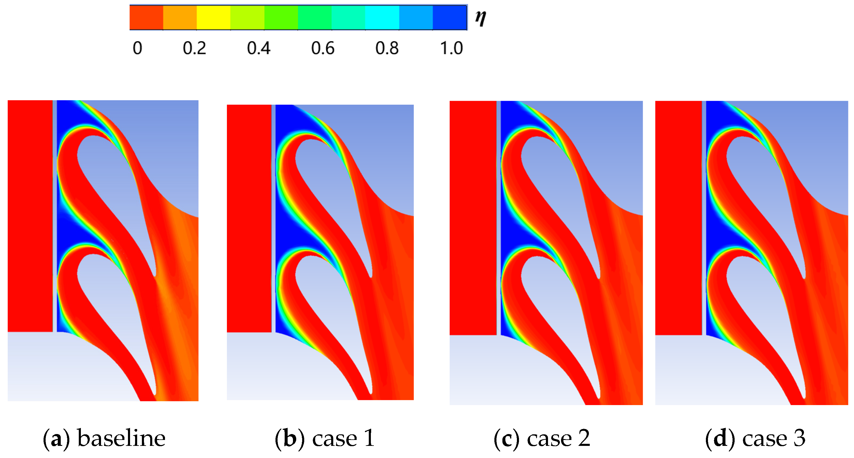
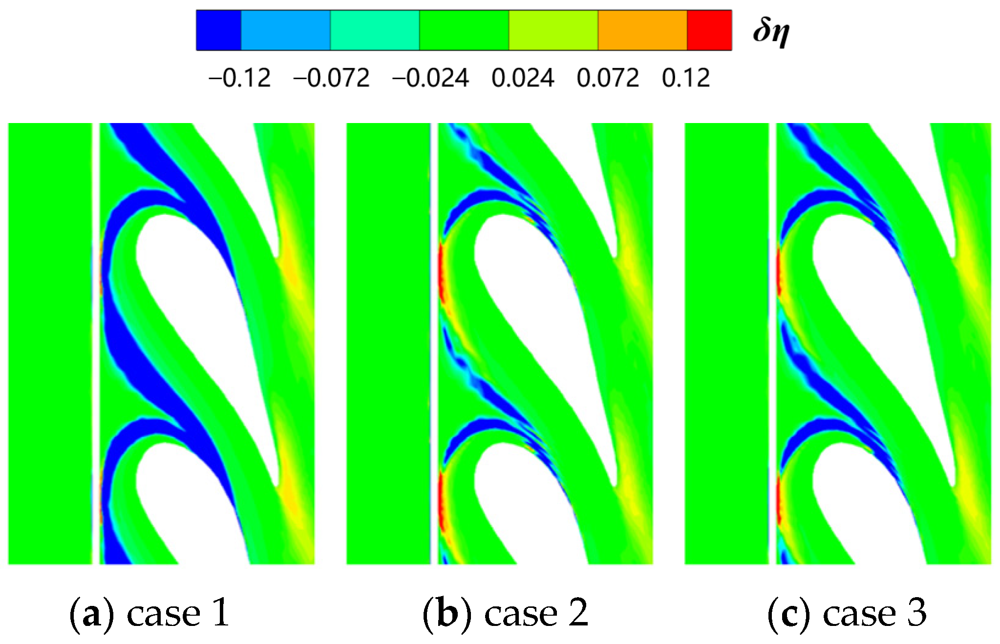
The transverse average adiabatic cooling effectiveness depicted in Figure 6 indicates that the cases with fillets provide better adiabatic cooling effectiveness than conventional structures. The adiabatic cooling effectiveness distributions of case 1 are better than other cases. The cooling performance on the upstream endwall (0 < x/L < 0.8) is changed significantly by the introduction of the slot fillet. Nevertheless, the cooling performance of downstream regions (0.8 < x/L < 1.0) is rarely impacted by the slot fillet configuration. Figure 7 shows the distribution of the adiabatic cooling effectiveness. The coverage of the slot coolant on the endwall is uneven. The coolant is confined to a narrow area downstream and there is a clear tendency to migrate towards the suction surface side. Therefore, the cooling flow has poor coverage of the leading-edge regions and the pressure side endwall. Furthermore, increasing the MFR significantly improves the coverage of the coolant. Figure 8 shows the distribution of the adiabatic cooling effectiveness difference δ, which is defined as:
η = η s η 0
where η s is the local adiabatic cooling effectiveness and η 0 is the baseline corresponding adiabatic cooling effectiveness. Through comparison, in case 1, there is an obvious blue zone near the leading edge and the boundary of the coolant coverage region, indicating that the spread of the coolant is strengthened by the introduction of the fillets with the same radius. In contrast, in case 2 and case 3, there are some red regions near the leading edge, indicating that the cooling effectiveness in this area is reduced. This shows that the fillet of slot strengthens the flow separation. At the same time, the blue region is much smaller than that of case 1. The slot fillets have little effect on the cooling characteristics in other places. Among them, the coverage of the coolant in case 1 reaches the maximum.
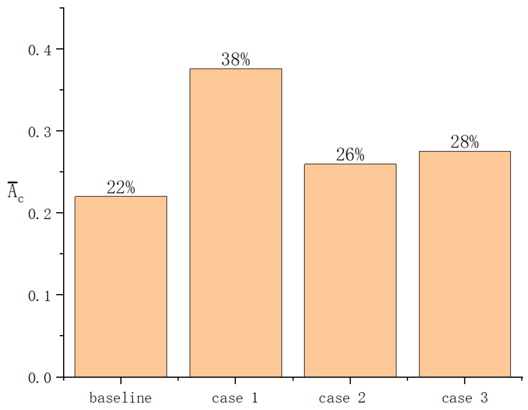
The distribution of the dimensionless effective cooling area ( A c ¯ ) is depicted in Figure 9, which is defined as:
A c ¯ = A c / A p
where A c is the area of the endwall where η > 0.1 and A p is the area of the endwall from the slot exit to the trailing edge of the vane. The results suggest that the case with slot fillet obtains larger coolant coverage than that of the case without the slot fillet. The case 1 achieves the largest overall adiabatic cooling effectiveness in comparison with the baseline due to the uniform film cooling coverage. The results indicate that case 1 achieves a 42% higher effective cooling area in comparison with the baseline. Compared with case 1, case 2 and case 3 have less effect on improving the adiabatic cooling effectiveness.
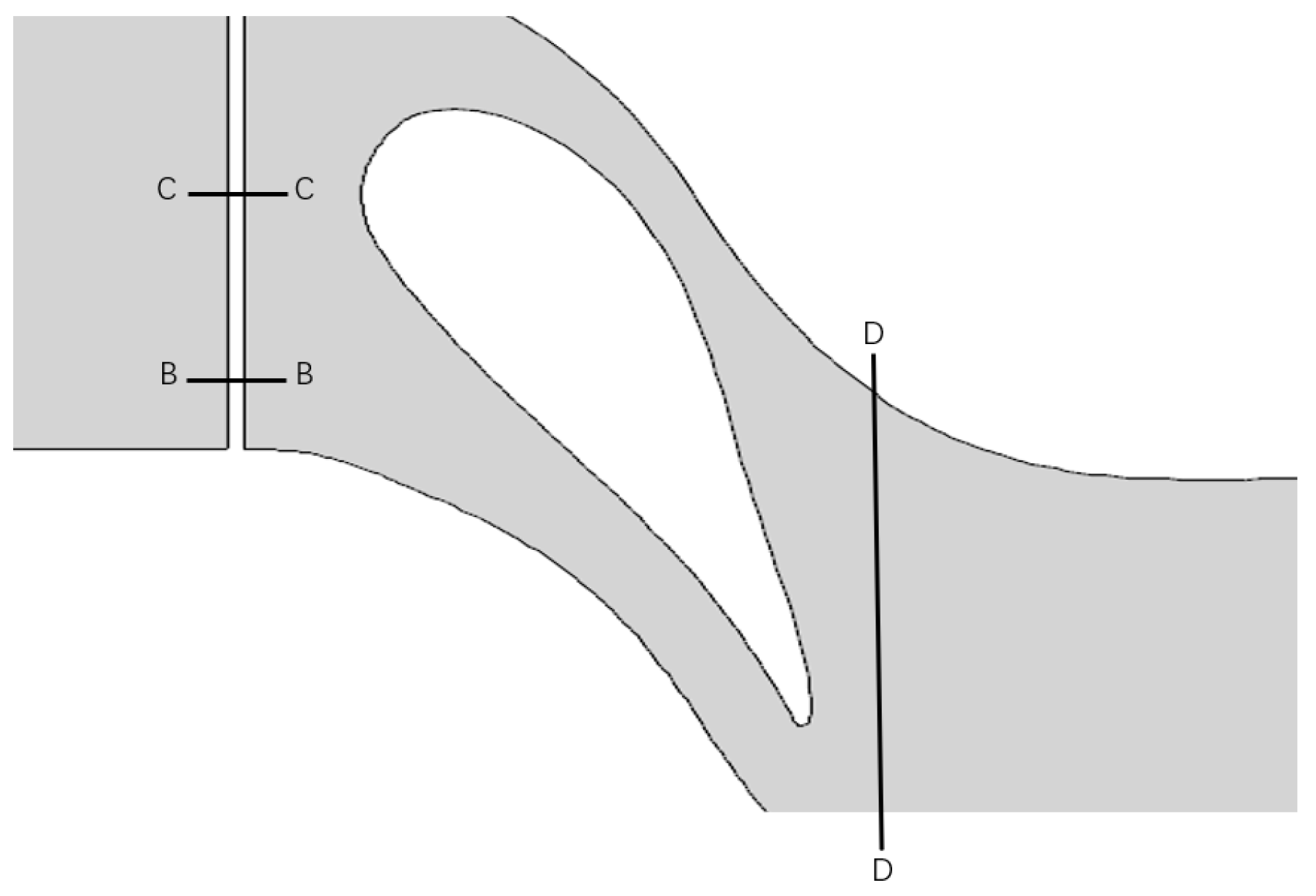
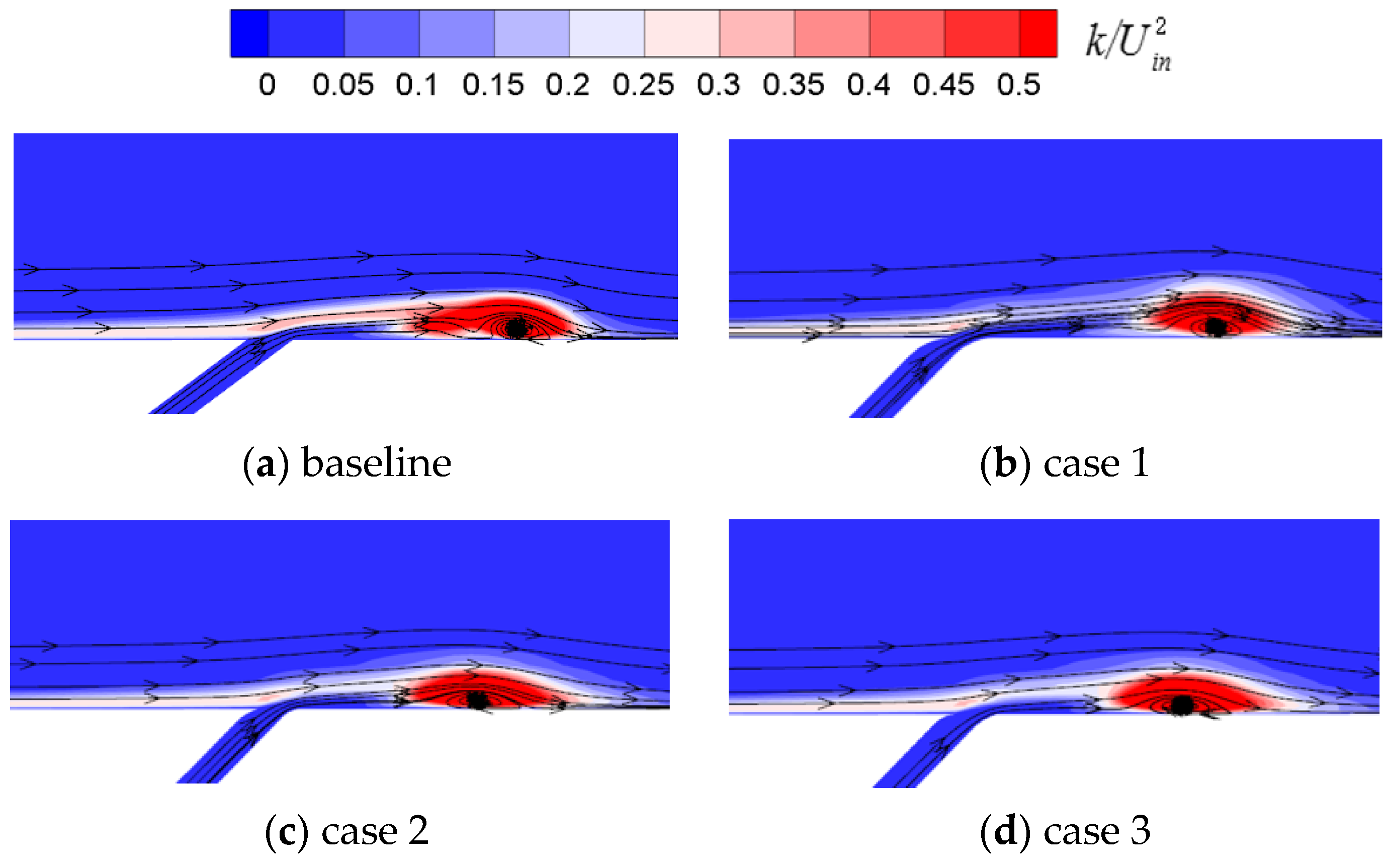
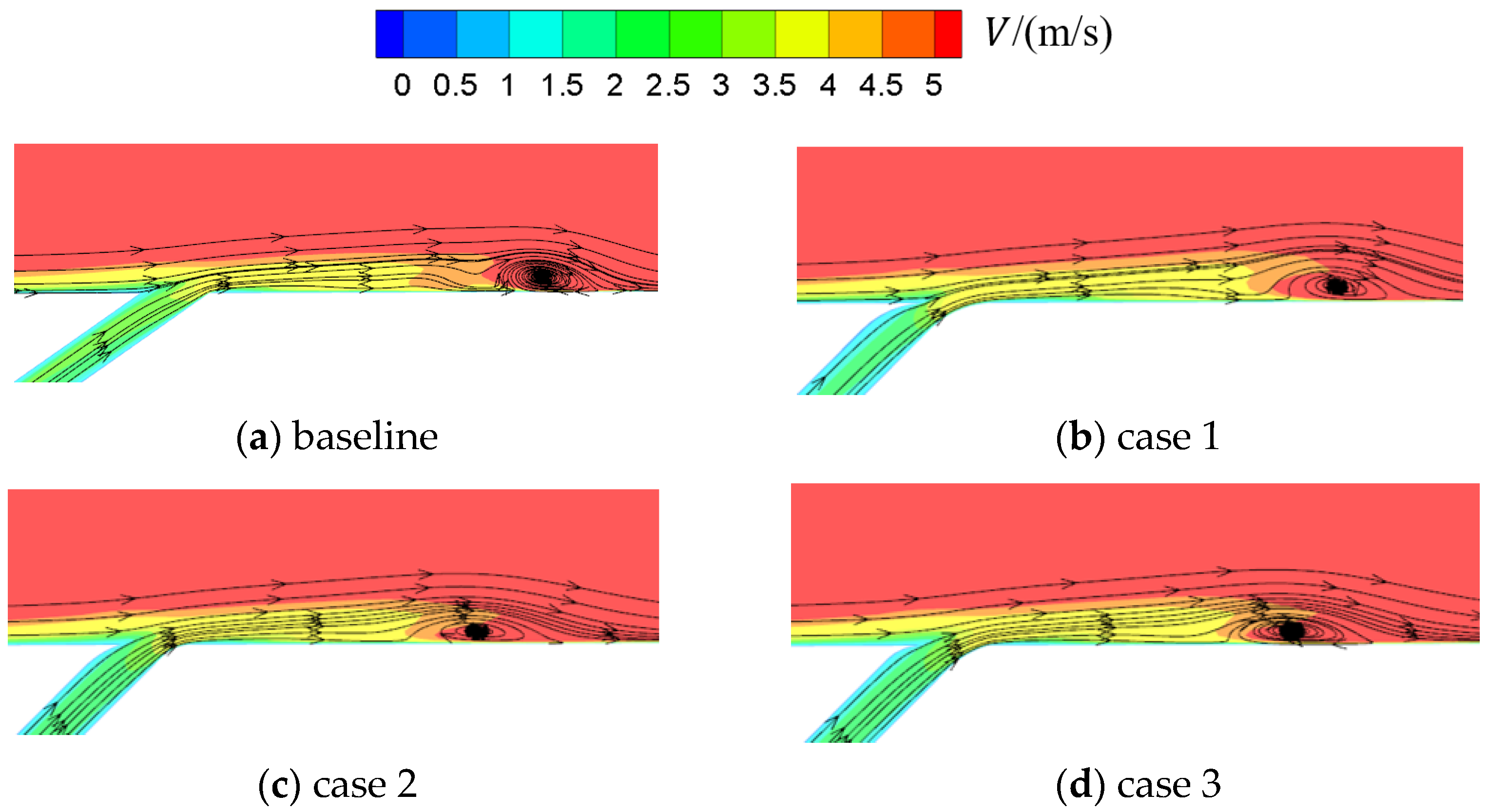
As shown in Figure 10, section B passes through the stagnation point. Section C is through the midpoint of two stagnation points. The two-dimensional streamline and turbulent kinetic energy distributions in section B are depicted in Figure 11. It is demonstrated that in case 1, the horseshoe vortex moves downstream. Meanwhile, the horseshoe vortex is drastically reduced in comparison with the baseline. The velocity distribution in section B is displayed in Figure 12. In case 1, the fillets with the same radius accelerate the boundary layer flow by changing the flow velocity. The slot fillets change the speed direction of the coolant near slot outlet, making the direction of the coolant more consistent with the mainstream. Therefore, the horse vortex moves downstream, leading to an expansion of the coolant coverage. In addition, the velocity at the slot outlet in case 2 and case 3 is lower than that in case 1. The velocity of the downstream boundary layer fluids in case 2 and case 3 is lower.

3.2. Influence of Slot Fillet

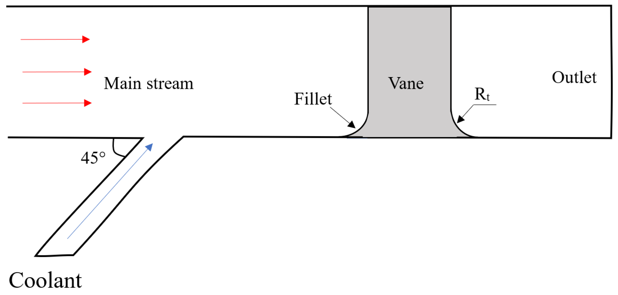
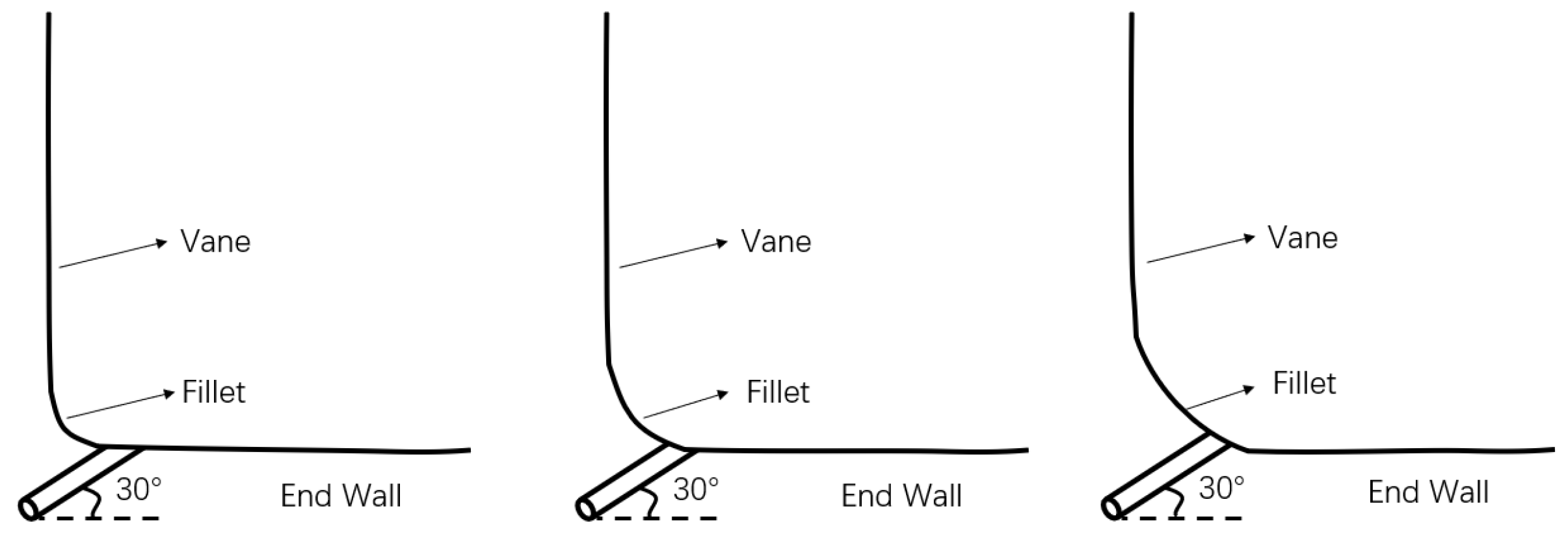
Due to the limit of machining technology, rounded corners are unavoidable at the intersection of two walls, such as at the vane root. Therefore, the impact of the vane root fillet on the cooling performance of the endwall is examined in this section. The model is displayed in Figure 13. The vane root fillet radius is defined as Rt, and 1% of the vane height is defined as R0.
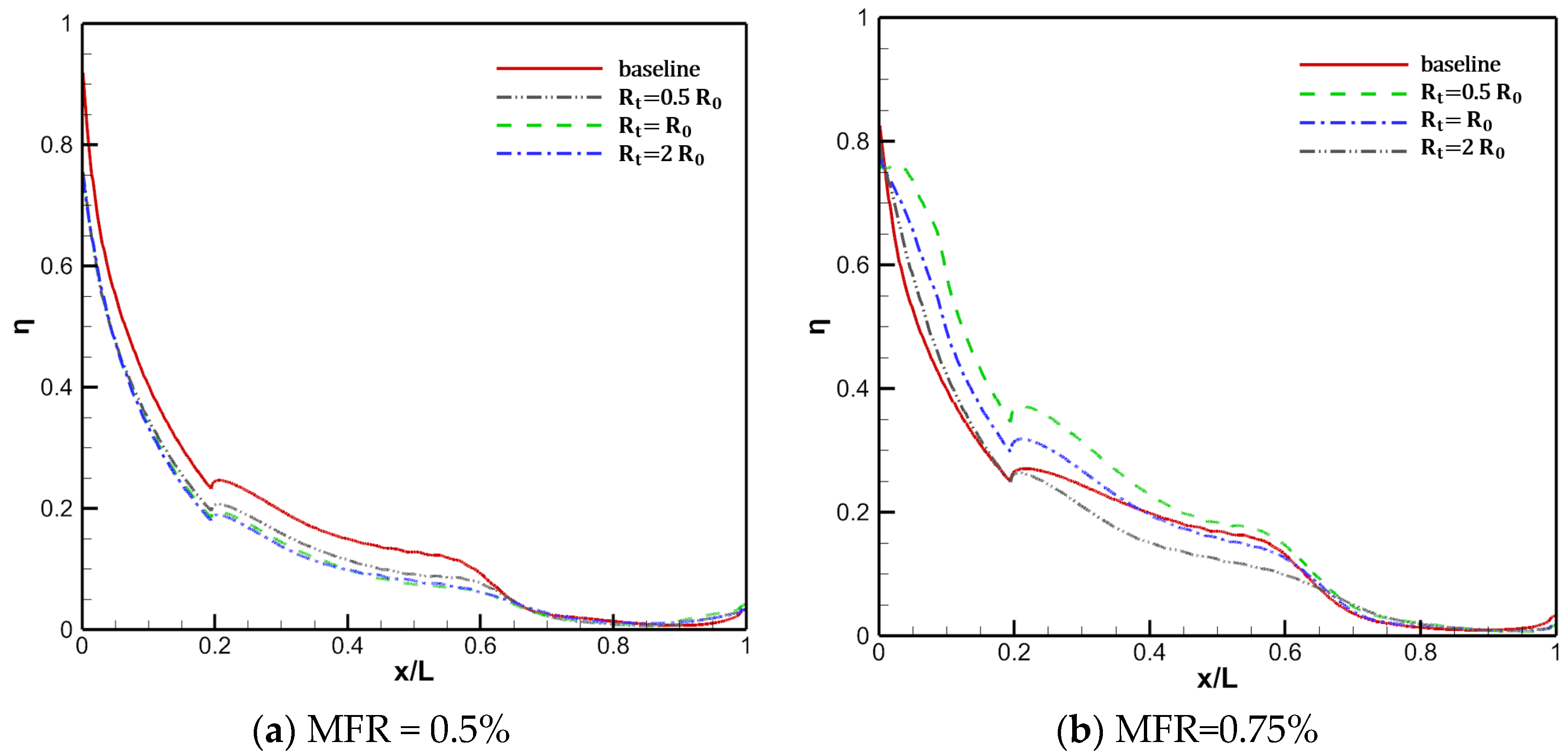
The transverse average adiabatic cooling effectiveness is depicted in Figure 14. It is shown that the adiabatic cooling effectiveness of the endwall presents a different variation pattern with the increase in MFR. At MFR = 0. 5%, the fillet radius has little impact on the cooling performance on the endwall. The case with the normal slot obtains the largest adiabatic cooling effectiveness of the endwall. However, the performance is different at MFR = 0. 75%. In detail, the increase in the fillet radius leads to a decrease in the adiabatic cooling effectiveness. Yet, for the leading-edge region (0 < x/L < 0.2), the introduction of the fillet still improves the cooling efficiency in comparison with the baseline. The introduction of the large vane fillet (2R0) obviously worsens the cooling performance of the mainstream region (0.2 < x/L < 0.8).
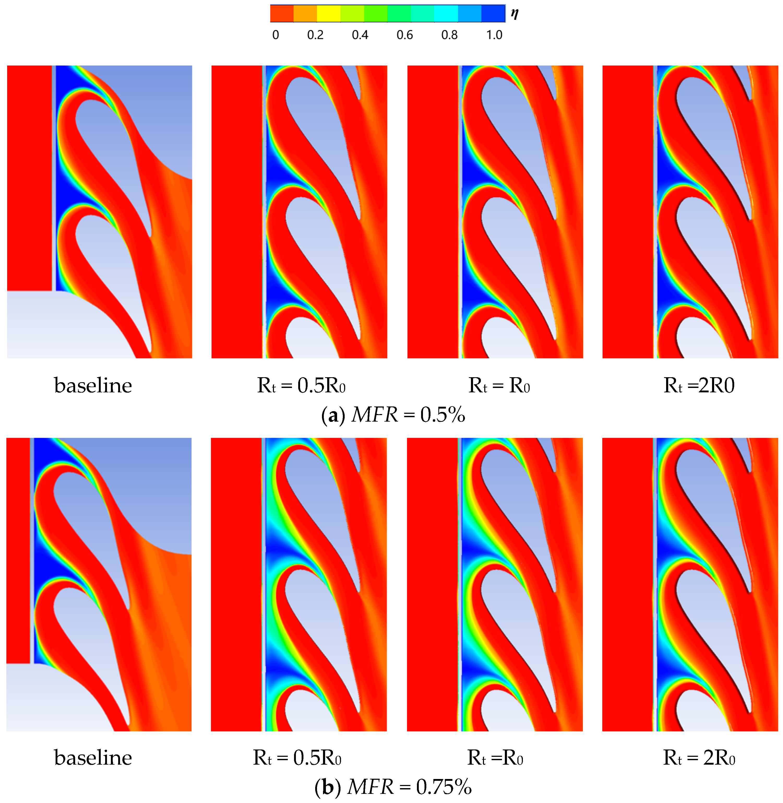
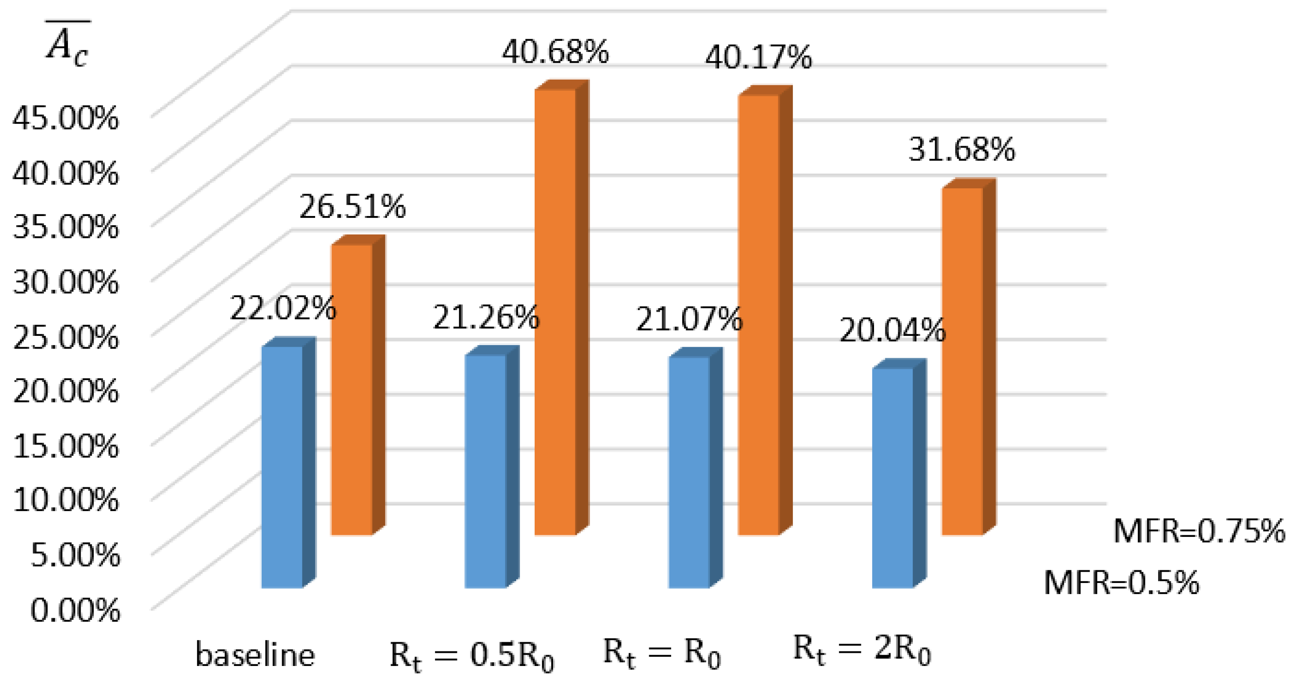
Figure 15 illustrates the adiabatic cooling effectiveness on the endwall and Figure 16 shows the dimensionless effective cooling area. From the results, it is obvious that MFR has a significant influence on the cooling performance of the endwall. The coverage of the coolant at the endwall is uneven. The slot coolant is confined to a narrow area downstream and there is a clear tendency to migrate towards the suction surface side. Therefore, the cooling flow has poor coverage of the leading-edge regions and the endwall near the pressure surface. The increase in MFR significantly improves the coverage area of the slot coolant. At MFR = 0.5%, the adiabatic cooling effectiveness near the leading edge is reduced by the introduction of the fillet. However, at MFR = 0.75%, the uncooled area near the leading edge and the pressure side is significantly limited by the introduction of the fillet, with a 53% increase in effective cooling area compared to the baseline. For the cases of Rt = R0 and 0.5R0, the coverage area of the coolant is increased slightly compared with the baseline.
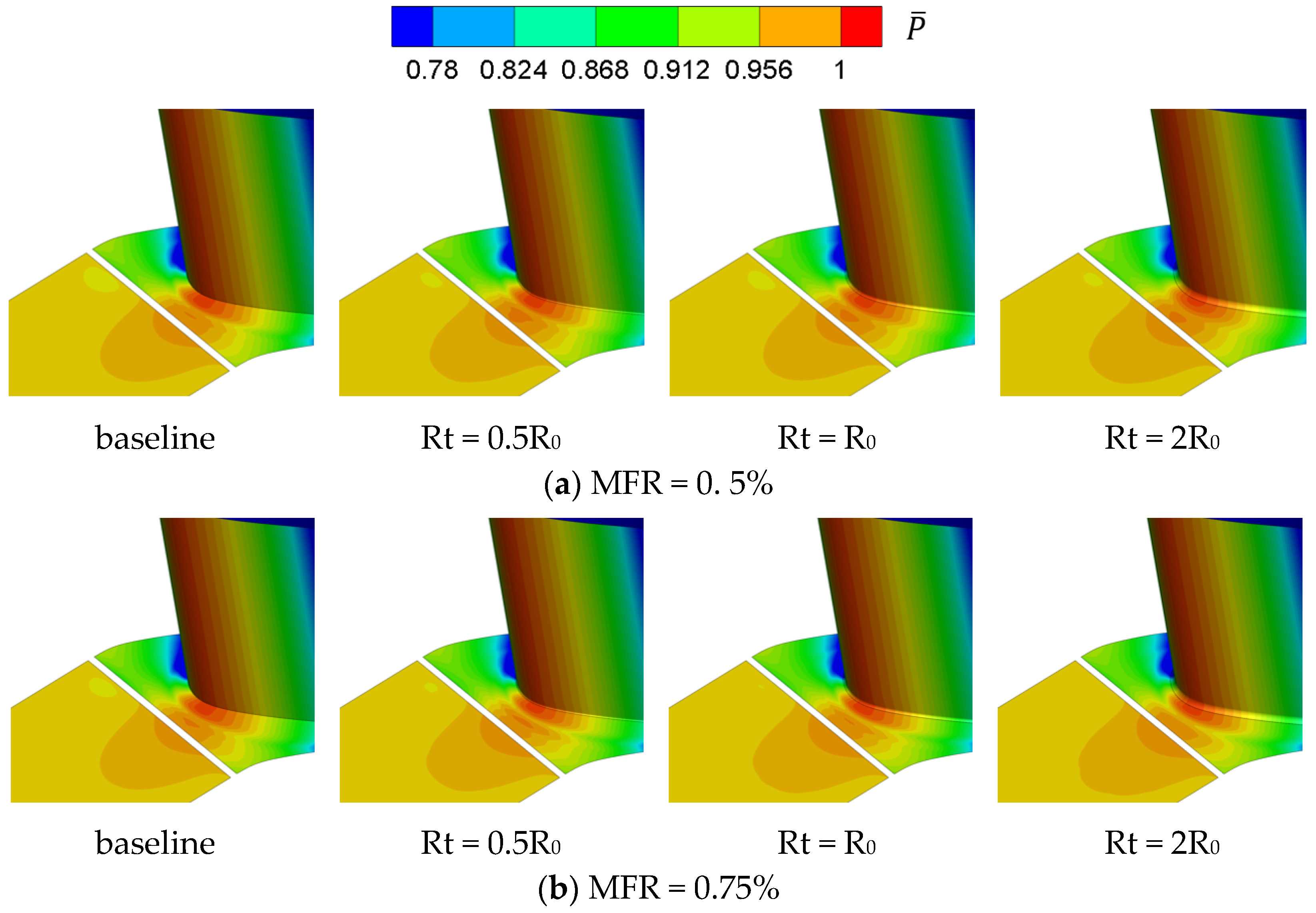
The pressure coefficient distributions of the vane and endwall are shown in Figure 17. The pressure coefficient ( P ¯ ) is defined as:
P ¯ = ( P P out ) / ( P in * P out )
where P is the local static pressure, Pout is the outlet static pressure, and Pin* is the inlet total pressure. The results suggest that there is a sizable high-pressure area close to the leading edge. The converse pressure gradient consumes the momentum of the boundary layer flow which leads to separation of the flow. There is also a high-pressure area at the slot outlet, and the non-uniformity of the pressure distribution at the slot outlet leads to the uneven distribution of the slot coolant. Most of the coolant flows out from the position far away from the vane leading edge. At MFR = 0.75%, the introduction of the fillet significantly limits the area of the high-pressure regions. Furthermore, the reduction of the fillet’s radius markedly shrinks the high-pressure region. In addition, the reduction of the high-pressure area near the leading edge delays the separation of the boundary layer, leading to a decrease of the uncovered area on the endwall. Because of the decrease of the pressure non-uniformity, the coverage of slot coolant spreads, improving the cooling performance near the leading edge.
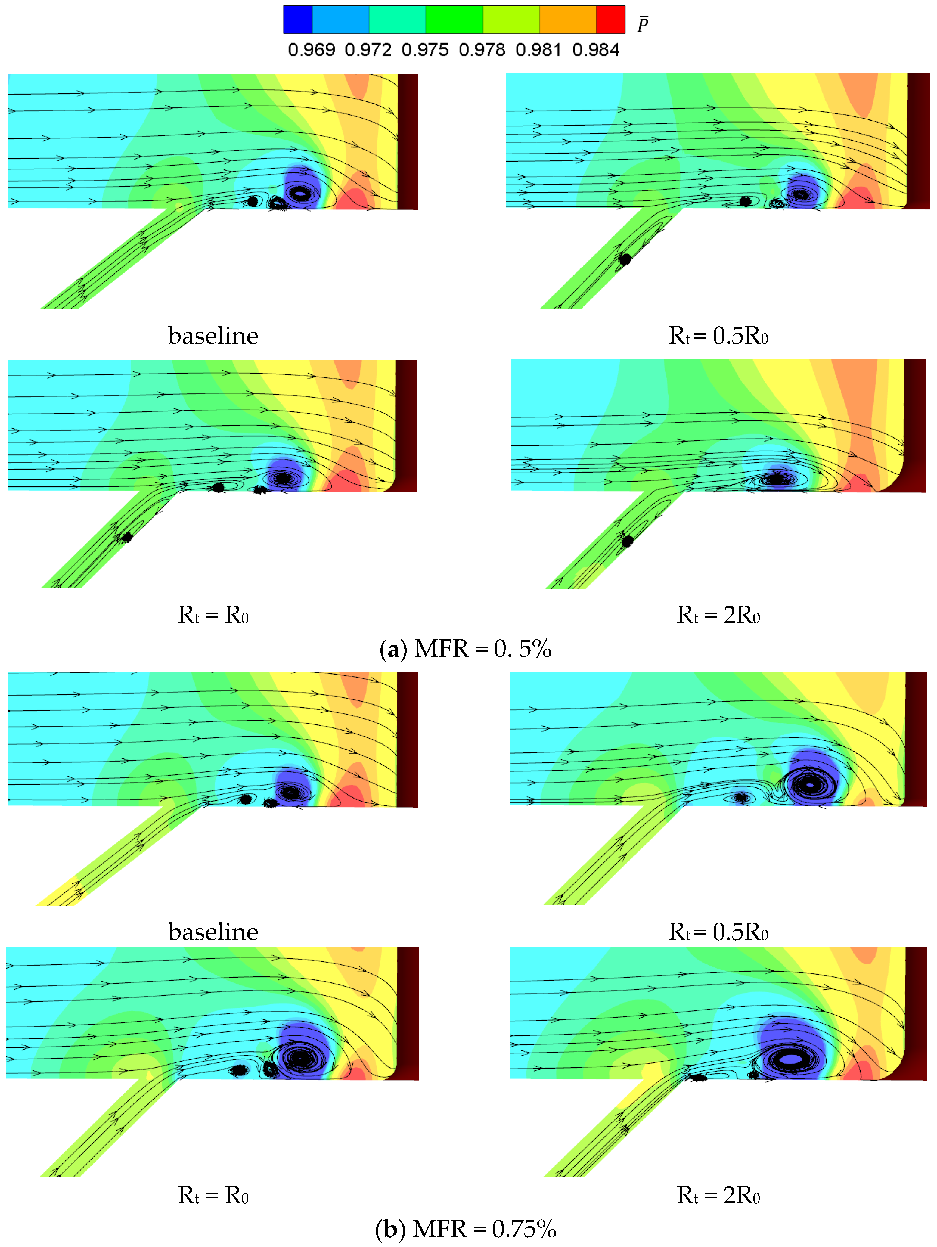
As the static pressure coefficient distributions in section C show in Figure 18, there are a large low-pressure area upstream of the horseshoe vortex and a high-pressure area close to the leading edge. Both of them contribute to the stagnation of flow near the leading edge. At MFR = 0.5%, the high-pressure region near the leading edge slightly shrinks at a large radius (Rt = 2R0). However, the increase of the fillet radius makes the boundary layer flow separate in advance. At MFR = 0.75%, increasing the fillet radius enlarges the high-pressure area near the leading edge and the low-pressure area upstream. Therefore, the area affected by the horseshoe vortex migrates upstream, greatly reducing the coolant coverage.
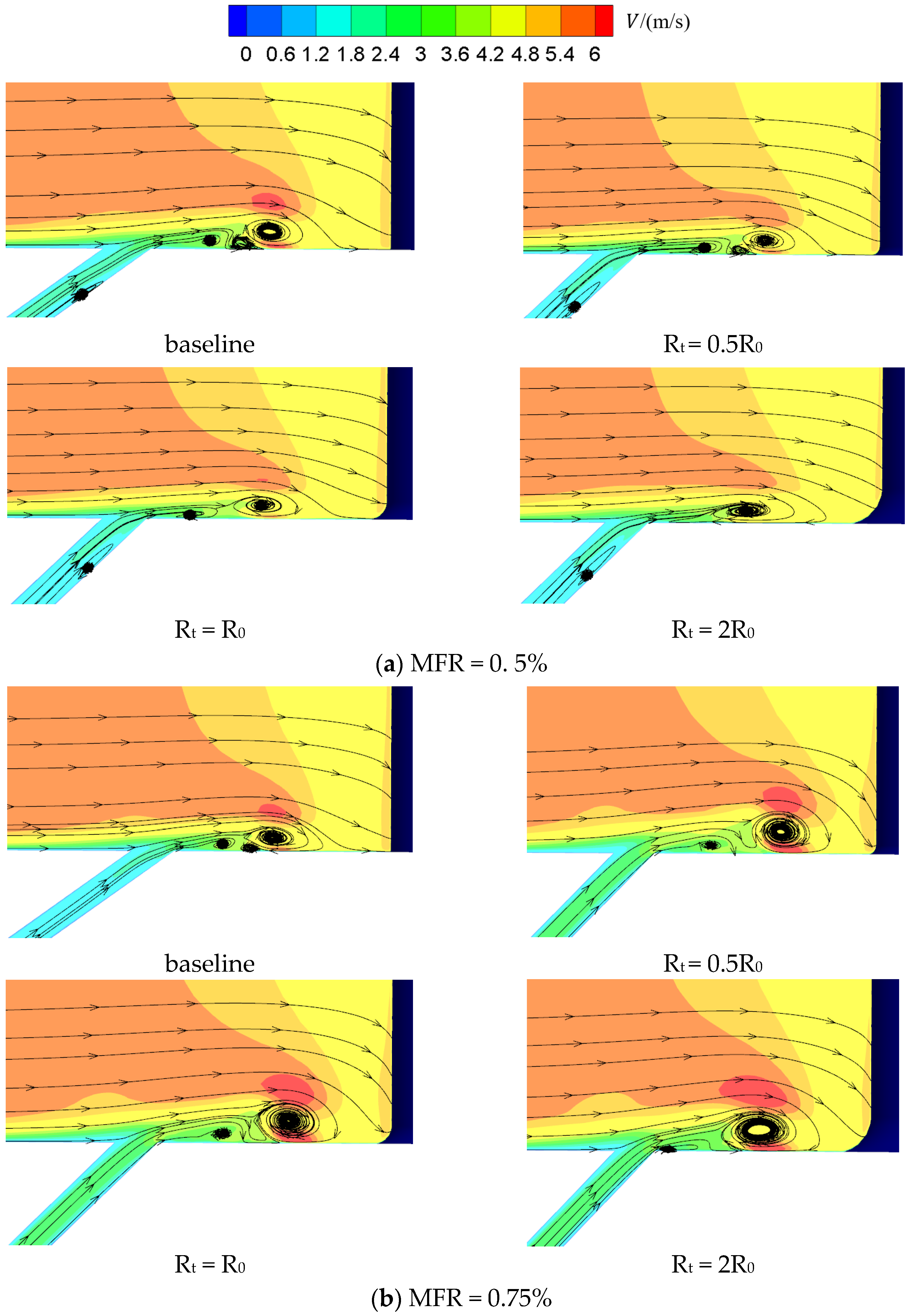
The velocity distribution in section C is presented in Figure 19. The results indicate that the thickness of the boundary layer of the mainstream gradually increases with the development of flow. Meanwhile, the velocity of flow gradually decreases as the airflow approaches the obstacle (vane). Influenced by the high-pressure region near the leading edge, the coolant velocity in section C is reduced obviously. The flow boundary layer is thickened after mixing with the slot coolant, causing a separation, known as the horseshoe vortex. In addition, due to the limit of the horseshoe vortex, the flow area of the upper layer of the fluid is shrunk obviously. This leads to an increase in the airflow speed. It can be seen from Figure 19 that at MFR = 0.5%, the boundary layer is thinner near the downstream slot. Because of the non-even pressure distribution, almost no coolant flows out at section C. This is the reason why the direction of the slot coolant is closer to the wall. At MFR = 0.75%, the radial component of the coolant velocity at the slot outlet is larger, generating a large separation vortex downstream. At MFR = 0.5%, there is almost no coolant flow at section C, and the position of the horseshoe vortex has little effect on adiabatic cooling effectiveness near the leading edge.

3.3. Influence of Vane Fillet

Discrete film holes are frequently used in engineering to provide specific cooling where slot coolant is seriously limited. The interaction of film holes and the fillet causes a significant influence on the flow performance near the outlet of the film holes. This section examines how the relative positions of film holes and vane root fillet affect the adiabatic cooling effectiveness on the endwall.
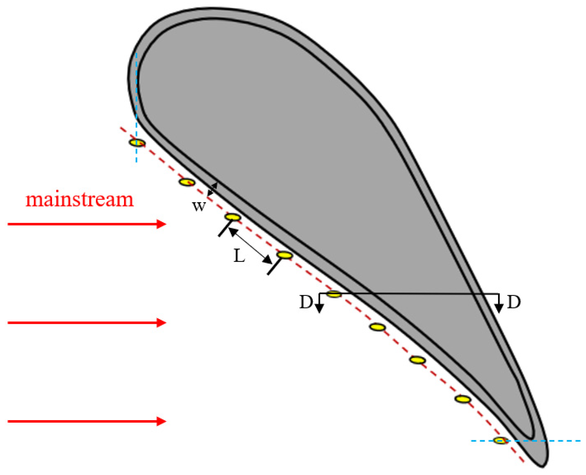
In the calculation, nine film holes are embedded in the endwall, like that displayed in Figure 20. The film holes are situated on an arc that is offset by a distance W from the blade profile. W is defined as 4% of the vane height. The film holes are equally spaced with an L = 57 mm distance between them. The diameter of the film holes is 4.6 mm and the film hole is in the same plane as the meridian surface. Figure 21 illustrates the relative position of film holes and fillet in Section D. In the calculation, MFR is 0.5%, and the blowing ratio M of the film hole coolant is set as 1.
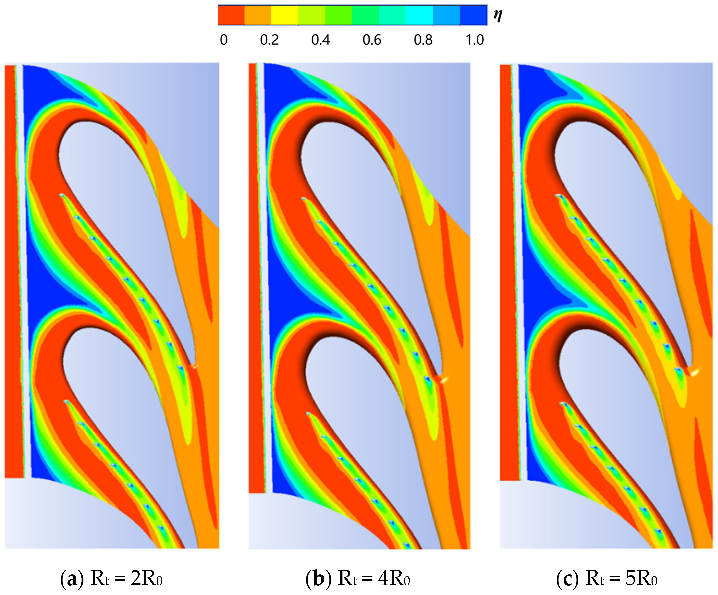
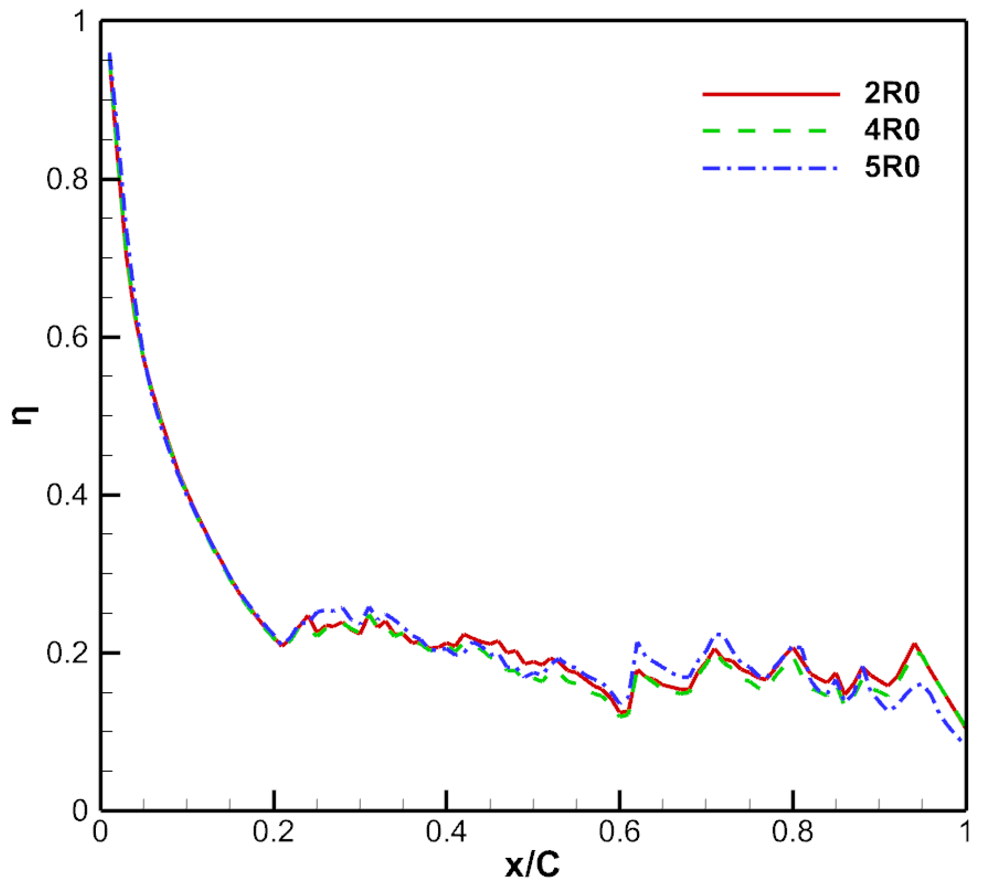
Figure 22 depicts the adiabatic cooling effectiveness distributions on the endwall, and Figure 23 shows the transverse average adiabatic cooling effectiveness of the endwall. The film hole coolant has great streamwise coverage, attaining a great cooling performance on the pressure side of the endwall. However, the film hole coolant has little influence on the cooling performance of the upstream and other mainstream regions. Although the film holes are close to the vane, there are still narrow high temperature regions without the coverage of the film hole coolant. The film hole coolant is slightly influenced by the mainstream vortex system. Therefore, the cooling performance of the film hole coolant is more effective in comparison with the slot coolant. In addition, the cooling area of the upstream film hole coolant can cover the downstream film hole. In the downstream passage, the film hole coolant still has great coverage. In addition, the film hole coolant has a strong lateral coverage, resulting in great overall adiabatic cooling effectiveness. The increase of the fillet radius significantly improves the transverse expansion of the film hole coolant. However, the streamwise coverage area of the film hole coolant near the vane trailing edge decreases.
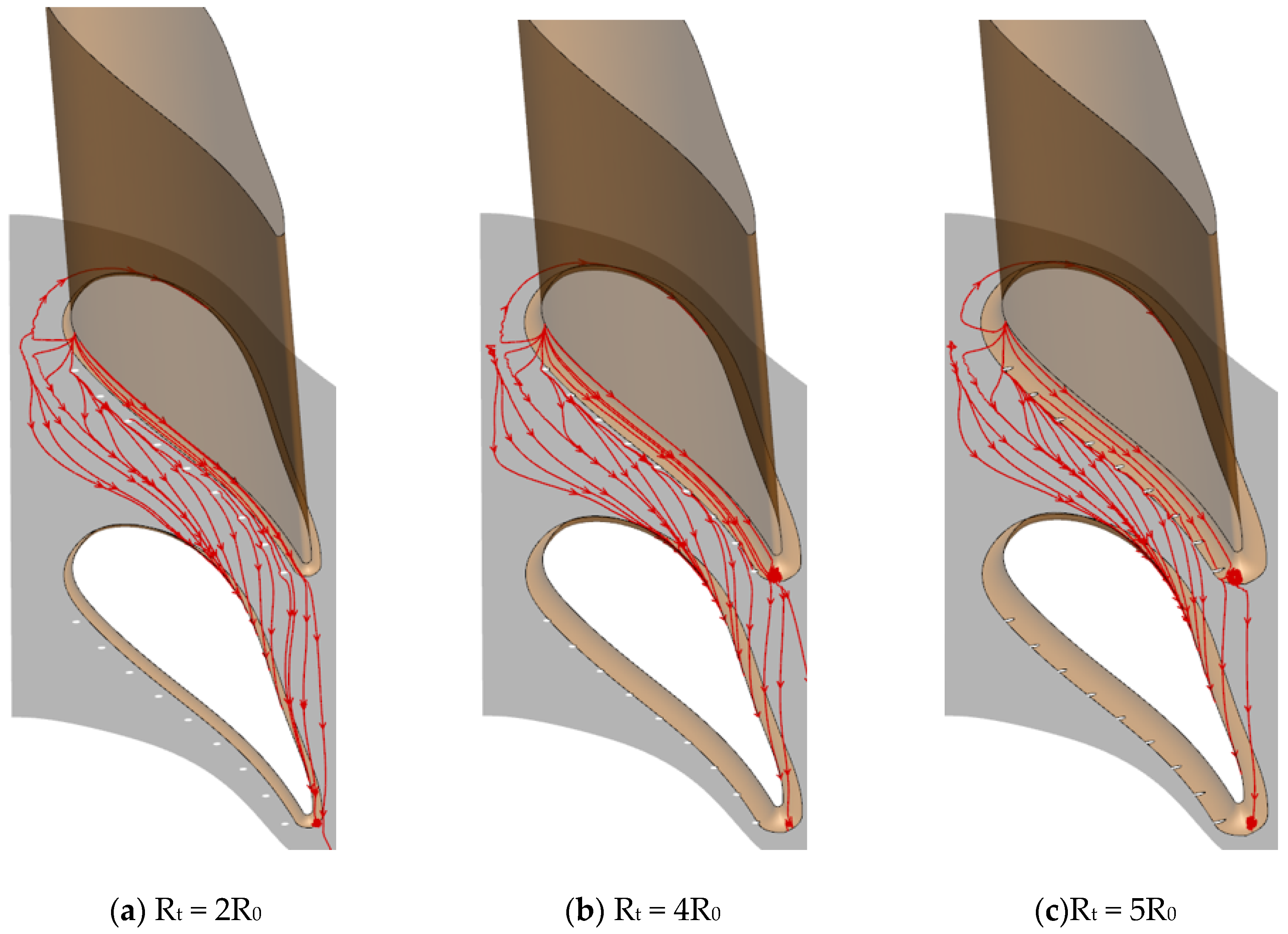
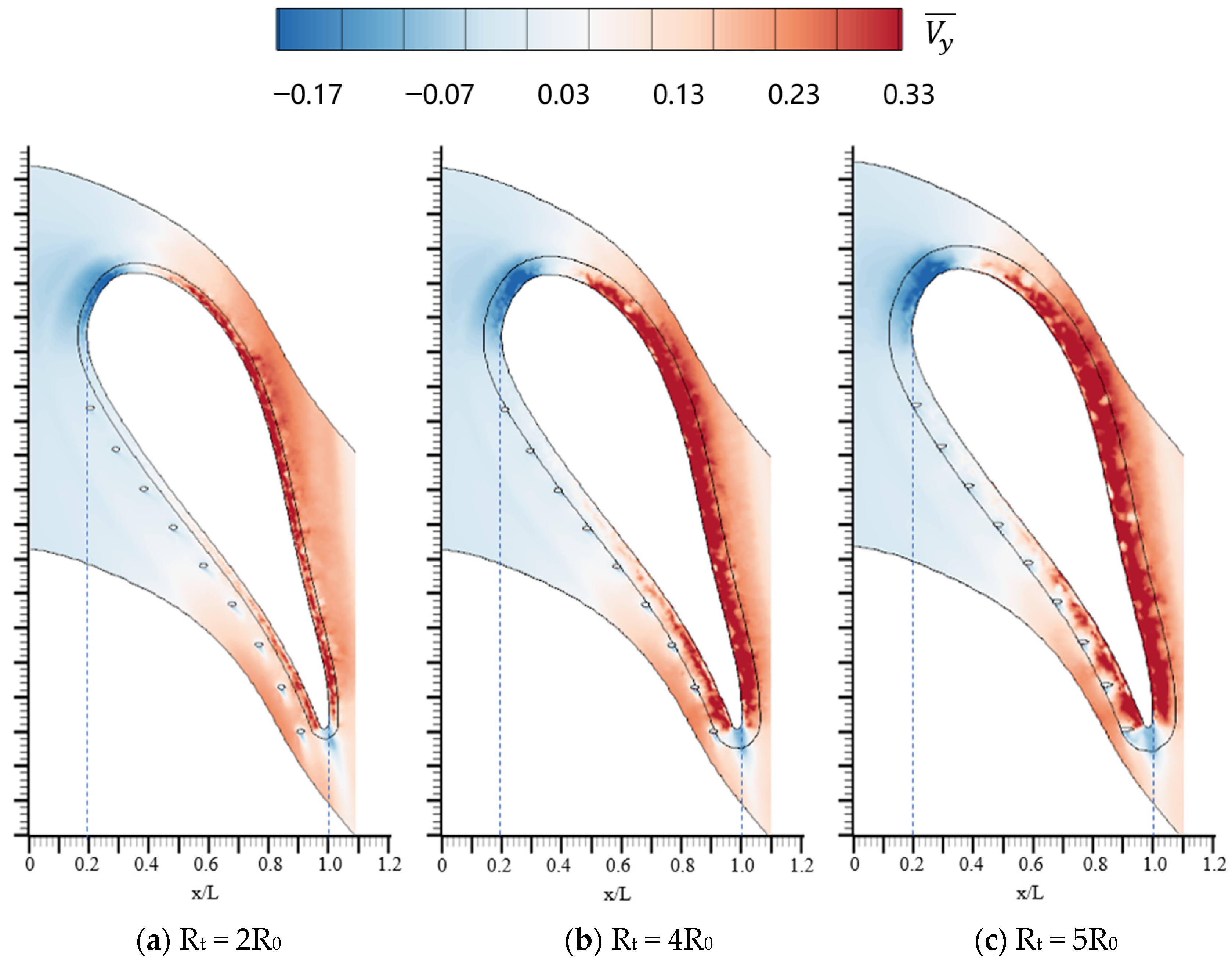
The limiting streamline on the endwall is presented in Figure 24 and the dimensionless circumferential velocity distribution on the endwall is shown in Figure 25. The dimensionless circumferential velocity ( V y ¯ ) is defined as:
V y ¯ = V y / V s ¯
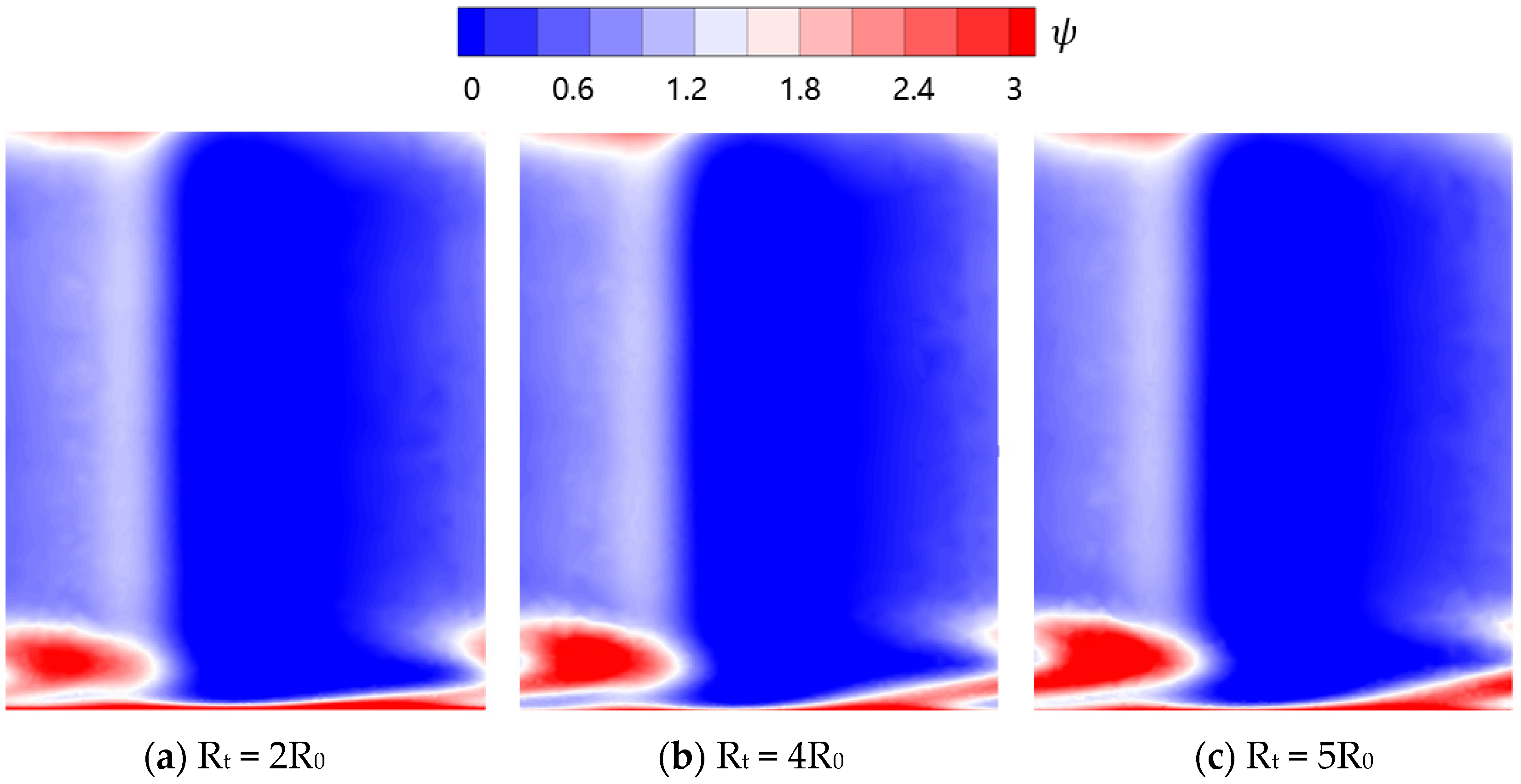
where V y is the pitchwise velocity and V s ¯ is the average velocity of the slot inlet coolant. A ring region can be found near the leading edge of the vane where the streamline direction does not coincide with the mainstream. As mentioned earlier, this is because this part of the flow is part of the horseshoe vortex. In the regions near the pressure side, the limiting streamline direction is roughly parallel to the wall. However, in the middle regions of the passage, the flow has a distinct lateral component due to the pressure gradient. Furthermore, the increase of the fillet radius greatly improves the lateral component of the airflow close to the endwall. This is attributed to the fact that the airflow turns into stagnation as it approaches the fillet, increasing the local static pressure. As a result, the coolant avoids the fillet, increasing in lateral components. The thermal loss coefficient ( ψ ) distribution in section D is depicted in Figure 26. It is defined as
ψ = 1 [ 1 ( P o u t p o u t * ) ( κ 1 κ ) out ] [ m ˙ T i n * + m ˙ c T c * ] m ˙ T i n * [ 1 ( P o u t p i n * ) ( κ 1 κ ) ] + m ˙ c T c * [ 1 ( P o u t p c * ) ( κ 1 κ ) c ]
where p i n * , p c * and m , m c are the total pressure and mass flow at the mainstream inlet and cooling jet inlet, respectively, p o u t * is the total pressure in the fow at the outlet surface, T i n * is the total inlet temperature of the main flow and T c * is the coolant’s total temperature. Figure 26 demonstrates that the increase in fillet radius significantly aggravates the thermal loss coefficient. As seen in the last figure, increasing the fillet radius strengthens the transverse migration of air flow close to the endwall, which increases the viscous penalty between boundary layer flow and non-viscous flow regions.

4. Conclusions

The present investigation serves to analyze the effects of the slot fillet and the vane root fillet on the aerothermal performance of the turbine vane endwall. The important conclusions are summarized below.
  • The altered coolant momentum caused by the slot fillet influences the interaction of the coolant and the mainstream in the boundary layer. In case 1, the slot fillets change the speed direction of the coolant near slot outlet, making the direction of the coolant more consistent with the mainstream. The coolant performance is greatly improved by introducing the slot fillets, with an increase of 42% in effective cooling area compared to the baseline.
  • The vane fillet with a small radius delays the separation of the boundary layer flow. It is attributed to the fact that the fillet with a small radius produces a pressure gradient opposed to the horseshoe vortex driving pressure gradient. Therefore, the horseshoe vortex is weakened by the introduction of the vane fillet. However, the fillet with a large radius makes the entire boundary layer flow separate early. The fillet with a large radius decreases the cooling performance.
  • The cooling performance of the film hole coolant is significantly influenced by the relative positions of the vane root fillet and the film holes. The increase of the fillet radius greatly improves the lateral component of the airflow close to the endwall. This is attributed to the fact that the airflow turns into stagnation as it approaches the fillet, increasing the local static pressure. As a result, the coolant avoids the fillet, increasing the lateral velocity component. The increase of the vane fillet radius improves the adiabatic cooling effectiveness, but aggravates the thermal loss coefficient.

Author Contributions

Conceptualization, K.D. and X.P.; methodology, X.P.; software, X.S.; validation, Z.Z.; formal analysis, K.D.; investigation, X.P.; resources, K.D.; data curation, X.P.; writing—original draft preparation, X.P.; writing—review and editing, K.D.; visualization, X.S.; supervision, C.L. All authors have read and agreed to the published version of the manuscript.

Funding

The authors gratefully acknowledge the support of the National Natural Science Foundation (No. 52006178) of China, National Key R&D Program of China (No. Y2019-VIII-0007-0168), the Fundamental Research Funds for the Central Universities and the Innovation Capacity Support Plan in Shaanxi Province of China (Grant No. 2023-CX-TD-19).

Institutional Review Board Statement

Not applicable.

Informed Consent Statement

Not applicable.

Data Availability Statement

The data that support the findings of this study are available from the corresponding author upon reasonable request.

Conflicts of Interest

The authors declare no conflict of interest.

Nomenclature

Nomenclatureη0baseline adiabatic cooling effectiveness
T η ¯ ρdensity
Taw η = ηadiabatic film cooling effectiveness
Aarea (m2) η ¯ laterally averaged adiabatic film cooling effectiveness
P*total pressure (Pa) η = area-averaged adiabatic film cooling effectiveness
Mblowing ratioψthermal loss coefficient
vvelocity (m·s–1)Subscripts
Ppressure (Pa)awadiabatic wall
Ttemperature (K)ccoolant
Ppressure coefficientmainstream
y+dimensionless wall—normal height of the first cell at walloutoutlet
Greek tvane root fillet
δηadiabatic cooling effectiveness differenceAcronyms
ηswall adiabatic cooling effectivenessMFRratio of the film coolant mass flow rate to the mainstream flow

References

  1. Hada, S.; Thole, K.A. Computational study of a midpassage gap and upstream slot on vane endwall film-cooling. Heat Transf. Parts A B 2011, 133, 011024. [Google Scholar] [CrossRef]
  2. Wang, H.P.; Olson, S.J.; Goldstein, R.J.; Eckert, E.R.G. Flow Visualization in a Linear Turbine Cascade of High Performance Turbine Blades. ASME J. Turbomach. 1997, 119, 1–8. [Google Scholar] [CrossRef]
  3. Langston, L.S.; Nice, M.L.; Hooper, R.M. Three-Dimensional Flow Within a Turbine Cascade Passage. ASME J. Turbomach. 1977, 99, 21–28. [Google Scholar] [CrossRef]
  4. Goldstein, R.J.; Spores, R.A. Turbulent Transport on the Endwall in the Region Between Adjacent Turbine Blades. ASME J. Turbomach. 1988, 110, 862–869. [Google Scholar] [CrossRef]
  5. Zhang, C.; Wang, W.; Wang, Z.; Tong, Z. Conjugate Heat Transfer Simulation of Overall Cooling Performance for Cratered Film Cooling Holes. Machines 2022, 10, 395. [Google Scholar] [CrossRef]
  6. Chowdhury, N.H.; Shiau, C.C.; Han, J.C.; Zhang, L.; Moon, H.K. Turbine vane endwall film cooling with slashface leakage and discrete hole configuration. ASME J. Turbomach. 2017, 139, 061003. [Google Scholar] [CrossRef]
  7. Gao, H.; Li, X.; Ren, J.; Jiang, H. Effect of leakage flow on the endwall cooling performance in high subsonic turbine cascade. Int. J. Therm. Sci. 2021, 170, 107140. [Google Scholar] [CrossRef]
  8. Tao, Z.; Yao, Y.; Zhu, P.; Song, L.; Li, J. Experimental and numerical study on film cooling effectiveness of an annular cascade endwall with different slot configuration. Int. J. Therm. Sci. 2020, 158, 106517. [Google Scholar] [CrossRef]
  9. Du, K.; Li, Z.G.; Li, J.; Sunden, B. Influence of the upstream slot geometry on the endwall cooling and phantom cooling of vane suction side surface. Appl. Therm. Eng. 2017, 121, 688–700. [Google Scholar] [CrossRef]
  10. Kim, J.; Sohn, H.-S.; Choi, S.; Hsu, W.-T.; Uedab, O.; Cho, H.H. Effect of misalignment at 2nd vane endwall on heat transfer with purge flow. Int. J. Heat Mass Transf. 2021, 170, 121034. [Google Scholar] [CrossRef]
  11. Zhang, Y.; Yuan, X. Turbine Endwall Film Cooling With Combustor-Turbine Interface Gap Leak-age Flow: Effect of Incidence Angle. J. Therm. Sci. 2013, 22, 135–144. [Google Scholar] [CrossRef]
  12. Wang, Z.; Feng, Z.; Zhang, X.; Peng, J.; Zhang, F.; Wu, X. Improving cooling performance and robustness of NGV endwall film cooling design using micro-scale ribs considering incidence effects. Energy 2022, 253, 124203. [Google Scholar] [CrossRef]
  13. Sharma, O.P.; Butler, T.L. Predictions of Endwall Losses and Secondary Flows in Axial Flow Turbine Cascades. ASME J. Turbomach. 1987, 109, 229–236. [Google Scholar] [CrossRef]
  14. Miao, X.; Zhang, Q.; Atkin, C.; Sun, Z.; Li, Y.S. Improving purge air cooling effectiveness by engineered end-wall surface structures- Part I: Duct flow. J. Turbomach. 2018, 140, 091001. [Google Scholar] [CrossRef]
  15. Rose, M.G. Non-axisymmetric end wall profiling in the HP NGVs of an axial flow gas turbine. In Proceedings of the ASME 1994 International Gas Turbine and Aeroengine Congress and Exposition, Hague, The Netherlands, 13–16 June 1994. [Google Scholar]
  16. Babu, S.; Kiran, K.N.; Tom, J.K.; Anish, S. Numerical Investigation on Effects of Profiled Endwall Over Purge Flow in Linear Turbine Cascade. In Proceedings of the 7th Asian Joint Workshop on Thermophysics and Fluid Science, Trivandrum, India, 24 November 2018. [Google Scholar]
  17. Mensch, A.; Thole, K.A. Overall Effectiveness and Flowfield Measurements for an Endwall with Non-axisymmetric Contouring. In Proceedings of the ASME Turbo Expo 2015: Turbine Technical Conference and Exposition, Montreal, QC, Canada, 15–19 June 2015. [Google Scholar]
  18. Sauer, H.; Müller, R.; Vogeler, K. Reduction of secondary flow losses in turbine cascades by leading edge modifications at the endwall. J. Turbomach. 2001, 123, 207–213. [Google Scholar] [CrossRef]
  19. Shih, T.I.P.; Lin, Y.L. Controlling secondary-flow structure by leading-edge airfoil fillet and inlet swirl to reduce aerodynamic loss and surface heat transfer. J. Turbomach. 2003, 125, 48–56. [Google Scholar] [CrossRef]
  20. Blair, M.F. An experimental study of heat transfer and film cooling on large-scale turbine endwalls. Am. Soc. Mech. Eng. 1974, 79788, V01AT01A033. [Google Scholar] [CrossRef] [Green Version]
  21. Du, K.; Li, J. Numerical study on the effects of slot injection configuration and endwall alignment mode on the film cooling performance of vane endwall. Int. J. Heat Mass Transf. 2016, 98, 768–777. [Google Scholar] [CrossRef]
Figure 1. Top view of the cascade and endwall cooling structure.
Machines 11 00729 g001
Figure 2. Layout of the cooling structure and vane profile in section A.
Machines 11 00729 g002
Figure 3. Computational grids.
Machines 11 00729 g003
Figure 4. Comparison of numerical prediction results of four common turbulence models and experimental results [21].
Machines 11 00729 g004
Figure 5. Schematic of the slots with fillets in section A.
Machines 11 00729 g005
Figure 6. Laterally averaged film effectiveness on the endwall.
Machines 11 00729 g006
Figure 7. Adiabatic cooling effectiveness contours on the endwall.
Machines 11 00729 g007
Figure 8. Adiabatic cooling effectiveness difference distribution on the endwall.
Machines 11 00729 g008
Figure 9. Non-dimensional effective cooling area on the endwall.
Machines 11 00729 g009
Figure 10. Location of sections.
Machines 11 00729 g010
Figure 11. Turbulent kinetic energy and streamline distribution in section B.
Machines 11 00729 g011
Figure 12. Velocity and streamline distribution in section B.
Machines 11 00729 g012
Figure 13. Schematic of model.
Machines 11 00729 g013
Figure 14. The transverse average adiabatic cooling effectiveness on the endwall.
Machines 11 00729 g014
Figure 15. Adiabatic cooling effectiveness contours on the endwall for various MFRs and radius of blade root fillet.
Machines 11 00729 g015
Figure 16. Non-dimensional effective coverage area on the endwall.
Machines 11 00729 g016
Figure 17. Static pressure coefficient contours on the endwall and vane.
Machines 11 00729 g017
Figure 18. Static pressure coefficient and streamline distributions in section C.
Machines 11 00729 g018
Figure 19. Velocity and streamline distributions in section C.
Machines 11 00729 g019
Figure 20. The model used in the calculation.
Machines 11 00729 g020
Figure 21. Diagram of the film holes and fillet in section D.
Machines 11 00729 g021
Figure 22. The adiabatic cooling effectiveness distributions on the endwall.
Machines 11 00729 g022
Figure 23. The transverse average adiabatic cooling effectiveness of the endwall.
Machines 11 00729 g023
Figure 24. The endwall surface’s limiting streamline distributions.
Machines 11 00729 g024
Figure 25. The dimensionless circumferential velocity distributions on the endwall.
Machines 11 00729 g025
Figure 26. The thermal loss coefficient distribution in section D.
Machines 11 00729 g026
Table 1. Geometric parameters of the computational model and boundary conditions.
ParametersValue
Chord length of blade C (mm)594
Axial chord of blade Ca (mm)293
Pitch/chord (P/C)0.77
Inlet total temperature (K)333.19
Inlet total pressure (kPa)107.64
Outlet static pressure (kPa)107
Inlet turbulence intensity1.0%
Inlet angle (°)0
Outlet angle (°)72
Coolant inlet total temperature (K)293.15
Table 2. Area-averaged adiabatic cooling effectiveness of different grid numbers.
Grid Numbers η ¯
4.5 × 1060.2625
7.0 × 1060.2726
9.0 × 1060.2742
1.1 × 1070.2746
Disclaimer/Publisher’s Note: The statements, opinions and data contained in all publications are solely those of the individual author(s) and contributor(s) and not of MDPI and/or the editor(s). MDPI and/or the editor(s) disclaim responsibility for any injury to people or property resulting from any ideas, methods, instructions or products referred to in the content.