1. Introduction
Permanent magnet synchronous motors (PMSMs) are widely used in vehicle traction applications, such as trains and automobiles, due to their high efficiency across a wide range of speeds. This is mainly because PMSMs do not suffer from rotor losses, which can cause inefficiencies in other types of motors, such as induction motors. In addition, PMSMs have high magnetic flux density, which allows for higher torque output and greater power density, giving them superior performance compared to other types of electric motors. PMSMs also have a high torque-to-inertia ratio, which makes them well suited for applications requiring high acceleration rates. These advantages in terms of efficiency, power density, and torque density have made PMSMs a popular choice for vehicle traction applications [
1,
2].
In recent years, there has been a growing interest among researchers to improve the efficiency, torque density, and torque ripples of PMSMs [
3]. To address these issues, various techniques have been explored, including the use of a dual-stator (DS) structure. This method has been the subject of extensive research in recent publications, as it is believed to enhance the amplitude and shape of the air gap flux density, leading to an increase in the output torque density of PMS motors. The DS structure is based on the energy conversion principle of electrical machines, which highlights the crucial role that air gap length plays in energy conversion. By increasing the energy stored in the air gap, more power can be converted, resulting in improved performance. The DS structure is an effective technique for achieving this, as it allows for a more efficient distribution of the air-gap magnetic flux, resulting in higher torque density and lower torque ripples [
4,
5,
6,
7].
The amplitude and shape of the air gap flux density play a critical role in determining the torque performance and overall efficiency of PMSMs. It is essential to increase the amplitude of the air gap flux density, even if it deviates from a perfect sinusoidal shape, in order to enhance the fundamental component of the flux density. However, maintaining a nearly sinusoidal shape is also important for improving torque performance [
8,
9]. Achieving an optimal design for the air gap flux density involves careful consideration of various factors, including the choice of magnetic materials, stator and rotor geometries, and winding arrangements.
The stator winding and magnets are the primary elements that affect the shape and amplitude of the air gap flux density. To enhance the performance of PMSMs, researchers have explored optimal stator winding arrangements and permanent magnet materials. Rare-earth permanent magnets are a proven and effective method to increase the amplitude of the air gap flux density [
10,
11]. However, the cost effectiveness of these magnets is a concern that needs to be addressed.
In addition to the aforementioned approaches, there have been efforts to develop flexible mechanical structures that can dynamically adjust the system’s permeability. This approach allows for the precise control of the amplitude and shape of the air gap flux density to achieve optimal results based on the system’s best mechanical position [
12].
The torque performance of PMSMs can be improved by using different permanent magnet arrangements. The most commonly used arrangements are surface-mounted PMSMs (SPMSMs) [
13], interior PMSMs (IPMSMs) [
14], and buried PMSMs (BPMSMs) [
15]. In SPMSMs, the magnets are placed on the rotor surface and the area between the magnets is not filled, resulting in constant stator inductance at the rated current [
16]. However, in IPMSMs and BPMSMs, the magnets are either placed inside the rotor core or on the surface with the area between magnets filled by the rotor core, causing the stator inductance to depend on the rotor position and be time-variant. BPMSMs are a modification of SPMSMs, providing higher air gap flux density and, therefore, higher output torque. The permanent magnets in these machines are arranged in a way that adjacent magnets have opposite magnetic poles (N-S magnetic poles). It is worth noting that the manufacturing process for SM-PMS and BPMS machines is considerably simpler compared to that of IPMS machines, primarily due to the placement of permanent magnets on the rotor surface. As a result, there has been significant interest among researchers in modifying SPMSMs and BPMSMs to enhance their performance capabilities [
17].
An example of altering magnet arrangement to achieve a higher air gap flux density for high-speed applications can be found in [
18,
19,
20], which presents an outer rotor permanent magnet synchronous motor (PMSM) utilizing a Halbach array arrangement. Researchers have focused on optimizing magnet placement, one of the two sources of flux, to enhance the amplitude and shape of the air gap flux density. The depth, quantity, and circumferential span of the magnets have also been optimized in the literature to improve the resulting air gap flux density [
21].
An additional technique that can enhance the torque characteristic of PMSMs involves modifying the flux transmission path by decreasing magnetic resistance. This can be achieved by filling almost half of the area between two adjacent poles with an iron rotor core and leaving the other half empty. The size of the iron rotor core can then be optimized to improve the amplitude and shape of the air gap flux density. This design is known as asymmetric salient SPMSMs (AS-SPMSMs) [
22].
The finite element method (FEM) is frequently used to analyze complex motor structures, as it has been demonstrated that the simulation results obtained by using FEM are highly consistent with experimental results, indicating the accuracy and reliability of FEM analysis [
23,
24,
25].
Improving the rotor structure is another viable method for achieving high efficiency, high torque density, and low torque ripples by enhancing the shape and amplitude of the radial component of the air gap flux density [
26]. Another crucial factor that affects the air gap flux density is the air gap length. Reducing the air gap length leads to an increase in the air gap flux amplitude. However, in practice, the air gap length cannot be excessively reduced due to manufacturing constraints and heat dissipation issues.
As mentioned previously, there are several methods to modify motor designs in order to enhance the torque performance of PMSMs. This study introduces a proposed structure for a dual-air-gap PMSM with a zig-zag magnet arrangement and a magnetic screen. The motor consists of two stators and a two-sided rotor, resulting in two separate air gaps for the inner and outer stators. The term “dual-air-gap (DAG)” is used to emphasize its higher torque density compared to single stator configurations, as explained earlier. The zig-zag magnet arrangement is chosen to isolate the flux between the inner and outer stator and rotor, effectively making them independent. This configuration helps minimize the flux path, potentially reducing core losses. However, the inner and outer flux still converge at the intersection point of the magnets. To address this, a magnetic screen is placed in the middle of the rotor between the inner and outer rotor PMs, effectively isolating the inner and outer regions. The electromagnetic characteristics of the proposed motor are analyzed using FEM. Additionally, a prototype is manufactured, and basic experiments are conducted to validate the findings observed in the simulations.
2. Structure of Proposed DAG-SPMSMs
The configuration options for DAG-PMSMs include two stators and one rotor, or one stator with two rotors. For this paper, the two-stator, one-rotor configuration is adopted. In PMSMs, the torque can be calculated by using some design parameters as follows [
27]:
where
is the air-gap flux density,
is the effective core length,
is the armature diameter,
is the winding factor, and
is the specific electric loading of the motor. In the case of DAG-PMSMs, both inner and outer motors contribute to the torque. The equation below shows that the torque contributed by each side depends on their specific electric loading and armature diameter. The ± sign takes into account the electromagnetic properties of the inner motor.
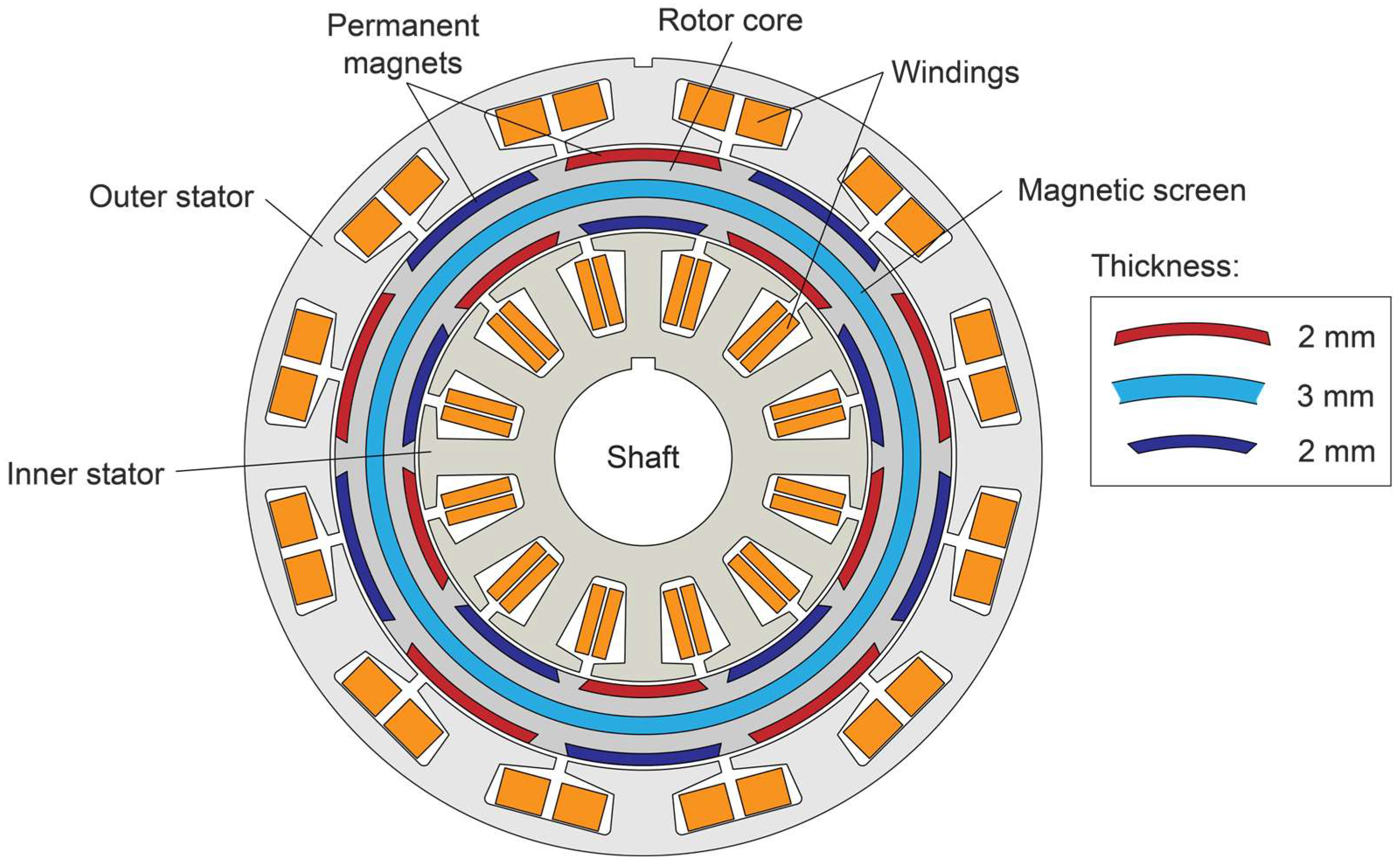
The proposed DAG-SPMSM is depicted in cross-sectional view in
Figure 1. The magnets located adjacent and opposite to each other exhibit different polarities, creating a flux path that effectively isolates the outer and inner magnets. This results in the two parts of the stator and rotor not interacting or being electromagnetically connected, thus creating an arrangement similar to having two motors. This unique feature distinguishes the proposed motor from those in [
28,
29], where the opposite magnets have the same polarity and the adjacent magnets have different polarities. In addition, the proposed magnet arrangement has the advantage of creating a short flux path, which results in the formation of a local loop between the inner magnets and the inner stator, and vice versa. This local loop can help to reduce core loss, and consequently increase the motor’s efficiency. To fully isolate the outer and inner magnet flux, a steel-based magnetic screen is embedded in between the rotor magnets. Additionally, the stator windings for both the inner and outer stators are connected in a series to ensure that the back-EMF exhibits the same phase and amplitude.
The specifications of the motor are presented in
Table 1. The proposed motor is designed for the propulsion of small ships. The stator and rotor cores are constructed from PNF core, which is a specialized material from POSCO (Pohang, Republic of Korea) that exhibits low core loss with a thickness of 0.27 mm. To isolate the outer and inner rotor magnetic flux, the magnetic screen is composed of SUS304, a stainless steel material containing nickel. Additionally, SUS304 is highly processable and does not harden through heat treatment, nor does it exhibit magnetism. Its use in the motor ensures full isolation of the inner and outer rotor magnetic flux.
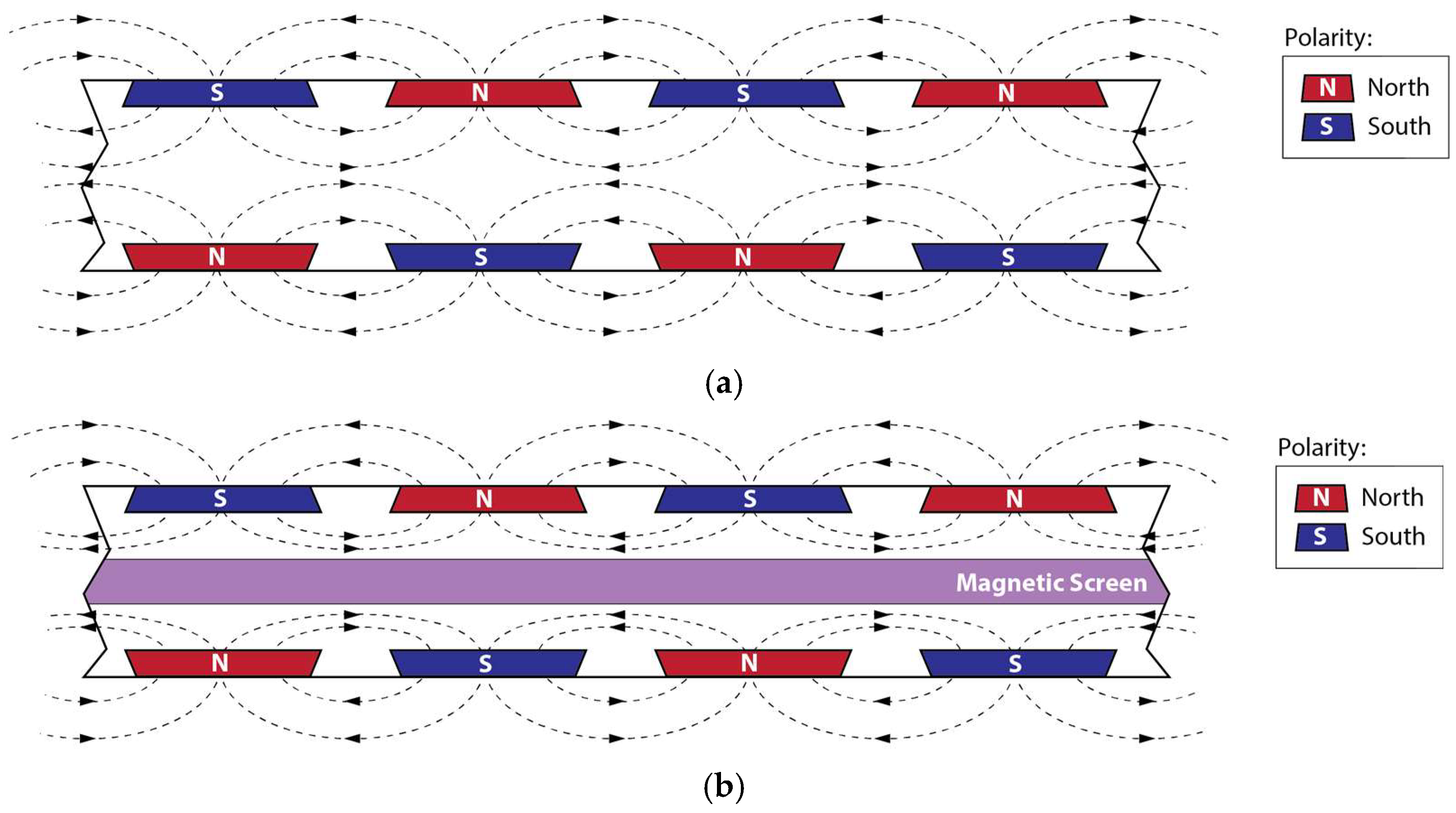
The contrast in rotor magnetic flux is demonstrated in
Figure 2 below. Despite adjusting the magnet polarity to isolate the inner and outer parts, creating a configuration similar to a combination of two motors, some areas of the rotor core still exhibit flux interaction, as depicted in
Figure 2a. To resolve this issue, a non-magnetic material can be introduced to separate them, as shown in
Figure 2b.
3. Finite Element Analysis Results
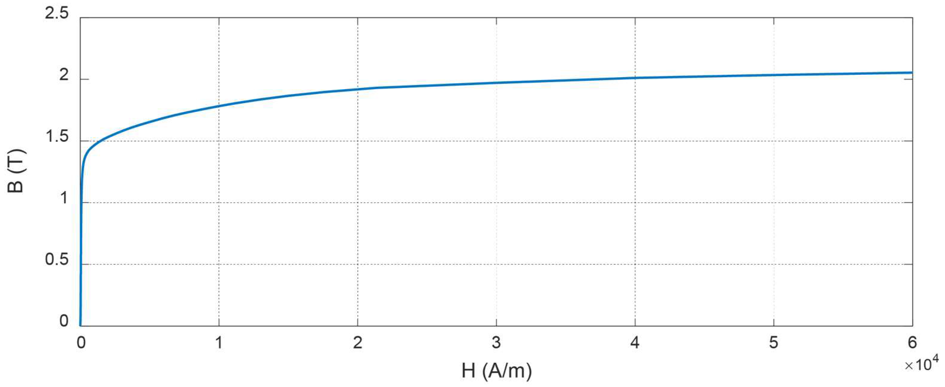
As was mentioned before, the core material used for the proposed motor is 27PNF1500 from POSCO. The magnetization curve of the material is shown in
Figure 3. The permanent magnet material is the general NdFe35. As can be seen in the figure, the core will reach saturation at around 2 (T).
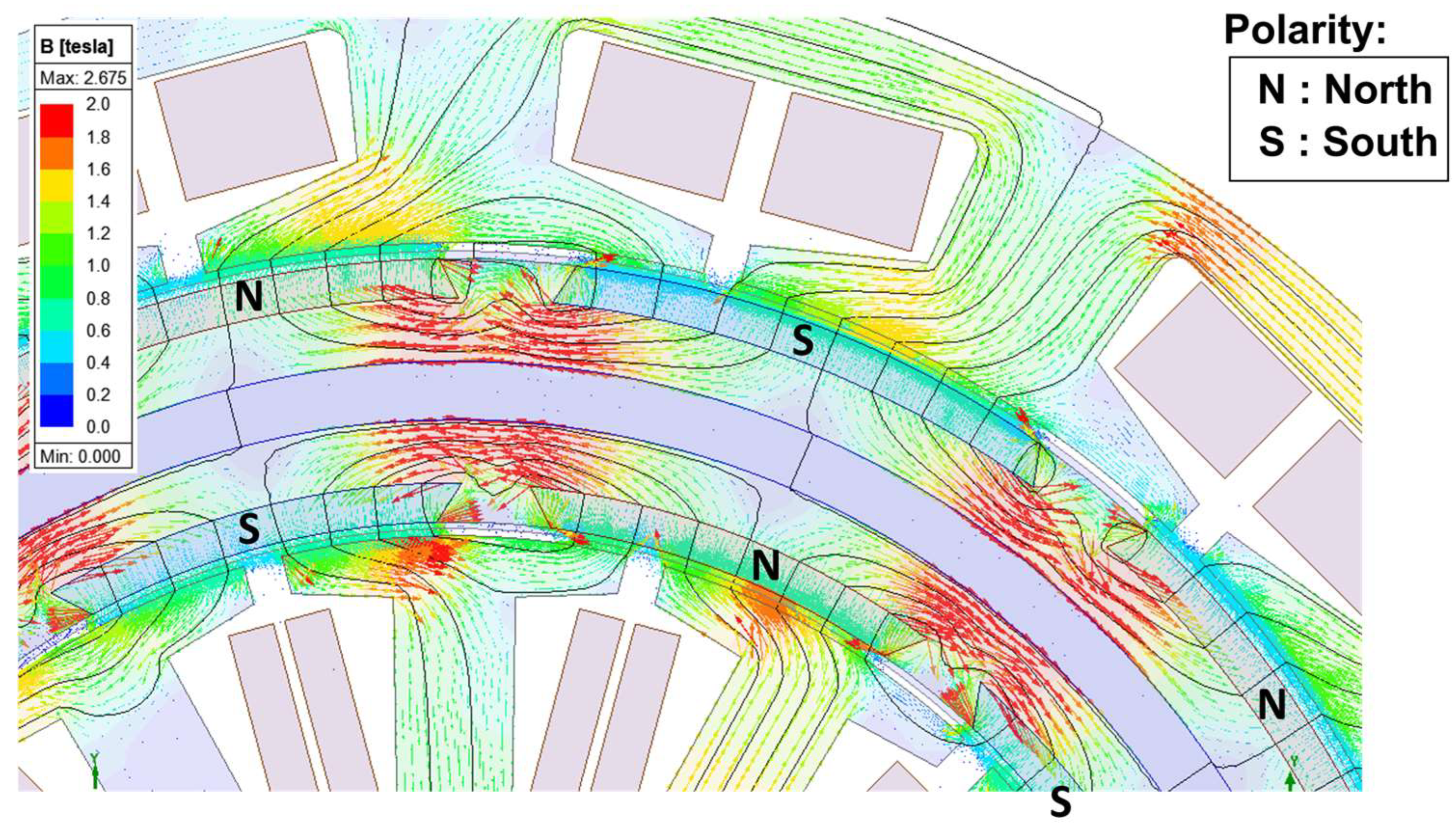
The first characteristic that must be examined is the flux path. As previously mentioned, the arrangement of magnet polarity in a zig-zag manner isolates the outer stator and magnets from the inner ones.
Figure 4 illustrates the flux lines (black) and the magnetic flux density vector (arrows). To provide clarity, the magnetic flux density is defined to range from 0 to 2 (T). It is apparent that the opposing flux generated by the magnets is directed toward the adjacent magnet, leaving a gap in the center for every outer-inner magnet pair. However, at the intersection of four magnets, the flux is still linked to the adjacent magnets, but the outer magnetic flux connects with the inner magnetic flux. This intersection has the highest flux density in the rotor core, making it impossible to entirely isolate the outer and inner sides by using only a permanent magnet arrangement.
In order to isolate the outer and inner rotor magnetic flux further, a magnetic screen is incorporated into the model, positioned between the outer and inner permanent magnets.
Figure 5 illustrates the impact of the magnetic screen on the flux path. The screen is placed to cover the gap between magnets that face each other, resulting in a similar main flux path, but with increased density due to the reduced effective area caused by the screen. Importantly, the introduction of the magnetic screen results in significant improvements in the isolation of the outer and inner rotor magnetic flux.
Flux density characteristics are closely related to both the flux path and the available core area for the flux to flow. In
Figure 6, a comparison of the flux density is shown for the proposed model with and without the magnetic screen.
Figure 6a illustrates that while the available core is wide, there is a gap between the magnets facing each other, indicating that the flux does not occupy all the available space. This results in low flux density in that area, where the flux flows toward the adjacent magnet instead. On the other hand, the intersection where the flux flow from four different magnets meet has the highest flux density.
As depicted in
Figure 6b, the flux density in the magnetic screen is almost zero. The lowest density can still be observed in the center of the core under the magnet, which can be attributed to the flow going in the direction of the adjacent magnet. The area with the highest density is still at the point where the magnet tips meet, and due to the reduced effective flux area, the density is higher compared to the model without a magnetic screen.
In addition to the rotor, the air-gap flux density can also be observed. By comparing
Figure 6a,b, it is evident that the air-gap flux density is lower when the screen is implemented compared to when it is not. Thus, it can be inferred that the torque is reduced when the screen is used for the same input current. Although the maximum flux density is higher in the model with the screen, a higher current is needed in the proposed model with the screen to produce the same torque as that without it. In the simulation, the rms phase current is 9 (A) for the original model, and it is increased to 10 (A) to compensate for the lower torque production.
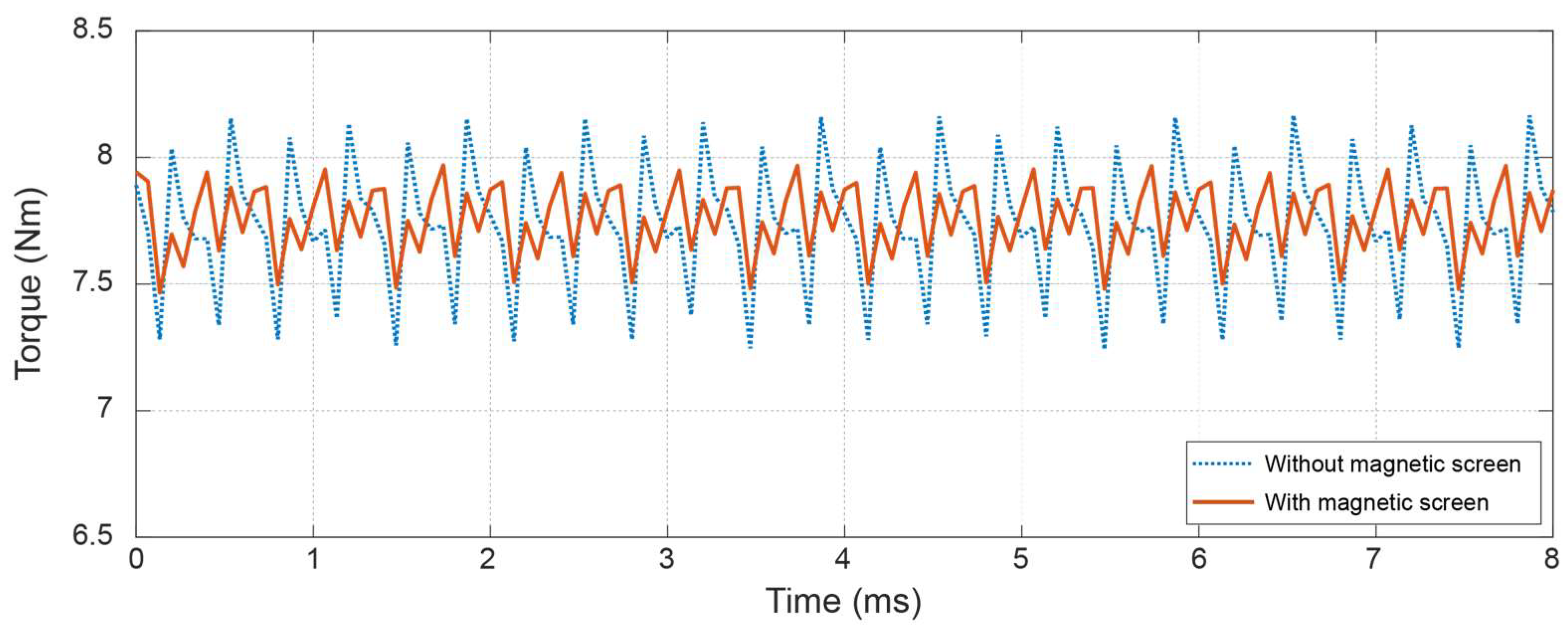
The torque comparison between the models with and without magnetic screen is shown in
Figure 7, with both models having the same average output torque. Despite requiring more current and having higher maximum flux density, the final model with the screen exhibits significantly reduced torque ripple compared to the model without screen. This is due to the higher flux density on the core between the magnets on the surface, which is a result of the insertion of the screen. The insertion of the screen reduces the space available for flux in the rotor, resulting in a more consistent average flux density near the air gap compared to the model without the magnetic screen, as shown in
Figure 6. It is widely known that flux ripple is the primary source of torque ripple in motors. Therefore, by reducing the flux ripple, a corresponding reduction in torque ripple can be achieved. The magnetic screen serves a dual purpose in this regard: not only does it isolate the two non-co-directional flux paths in the motor, but it also helps decrease the flux ripple and, consequently, the torque ripple. The torque ripple (
) can be calculated using the following equation, which is based on the squared torque error (
) between the measured torque (
) and the average torque (
) [
30,
31]:
Here,
represents the number of predetermined samples. By applying Equation (3), the torque ripple for the model without the magnetic screen is approximately almost twice that of the proposed model. Specifically, the torque ripple for the model without the screen is calculated to be 28.21%, while the torque ripple for the proposed motor with the screen is determined to be 15.27%.
Table 2 presents a comprehensive numerical comparison between the two models. The final model, which incorporates the magnetic screen, shows a 23% increase in copper loss compared to the original model. This increase is due to the additional current required to produce the same torque output. Additionally, the final model incurs magnetic screen losses. However, as anticipated, the final model demonstrates a reduction in core loss by approximately 17% and a significant reduction of nearly 50% in permanent magnet (PM) losses. These improvements can be attributed to the optimized flux paths created by the magnetic screen. It is worth noting that the mechanical loss remains constant for both models, as it is calculated as 1% of the power output. This loss component is independent of the specific model configuration. Overall, the total loss for the final model is approximately 10% lower compared to the original model. This reduction in total losses indicates the improved efficiency and performance of the final model with the magnetic screen.
4. Experimental Results
To validate its performance, the motor was manufactured and an experimental setup was arranged, as depicted in
Figure 8. The proposed motor, with a double stator structure and the rotor in between, is mounted on a specialized frame. A servo is used to apply a controllable load, and a torque/speed sensor measures the output on the shaft. The motor is driven by a commercial AC drive from Yaskawa (Kitakyushu, Japan), a GA700. The input and output power are measured using a power analyzer, which enables the calculation of efficiency.
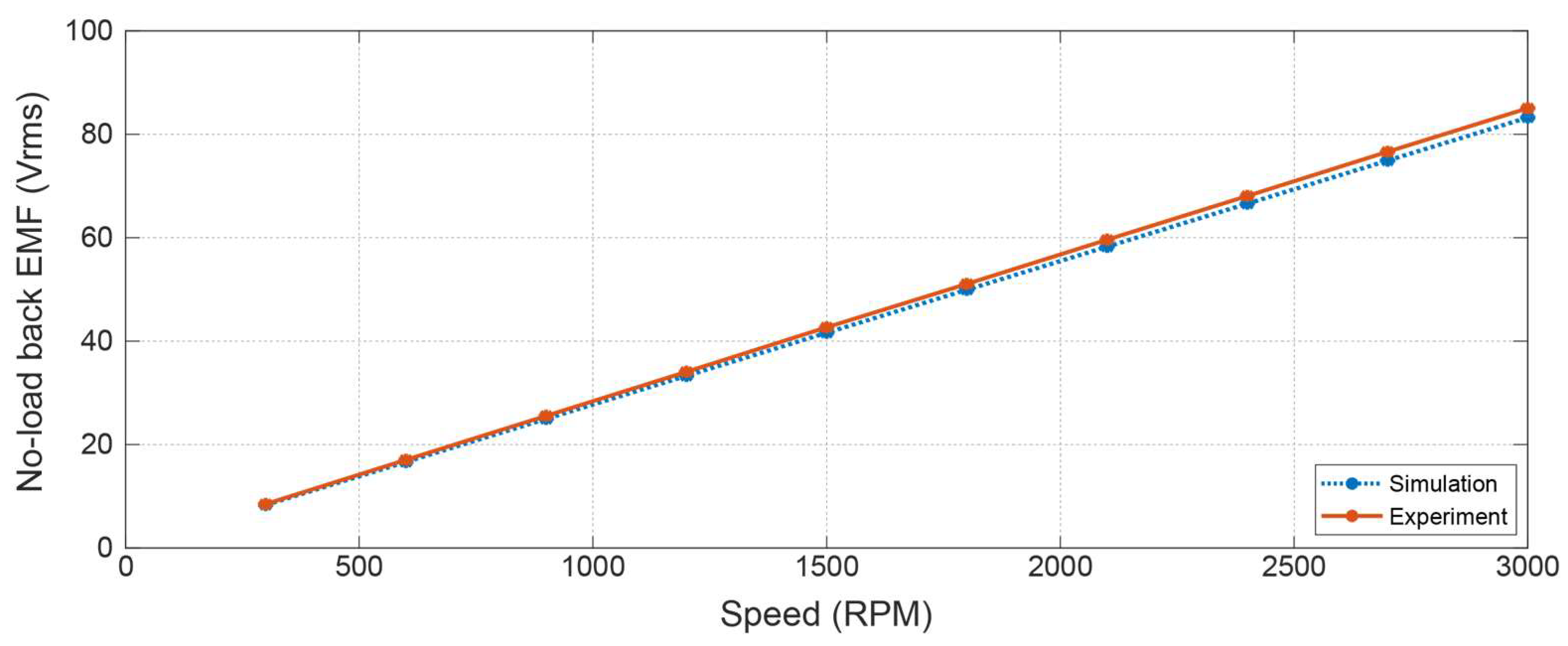
First, the no-load back-EMF is measured, and the corresponding results are presented in
Figure 9. The results show a close alignment between the manufactured motor and the design, with an average error rate of 2.6% observed across all recorded speed points.
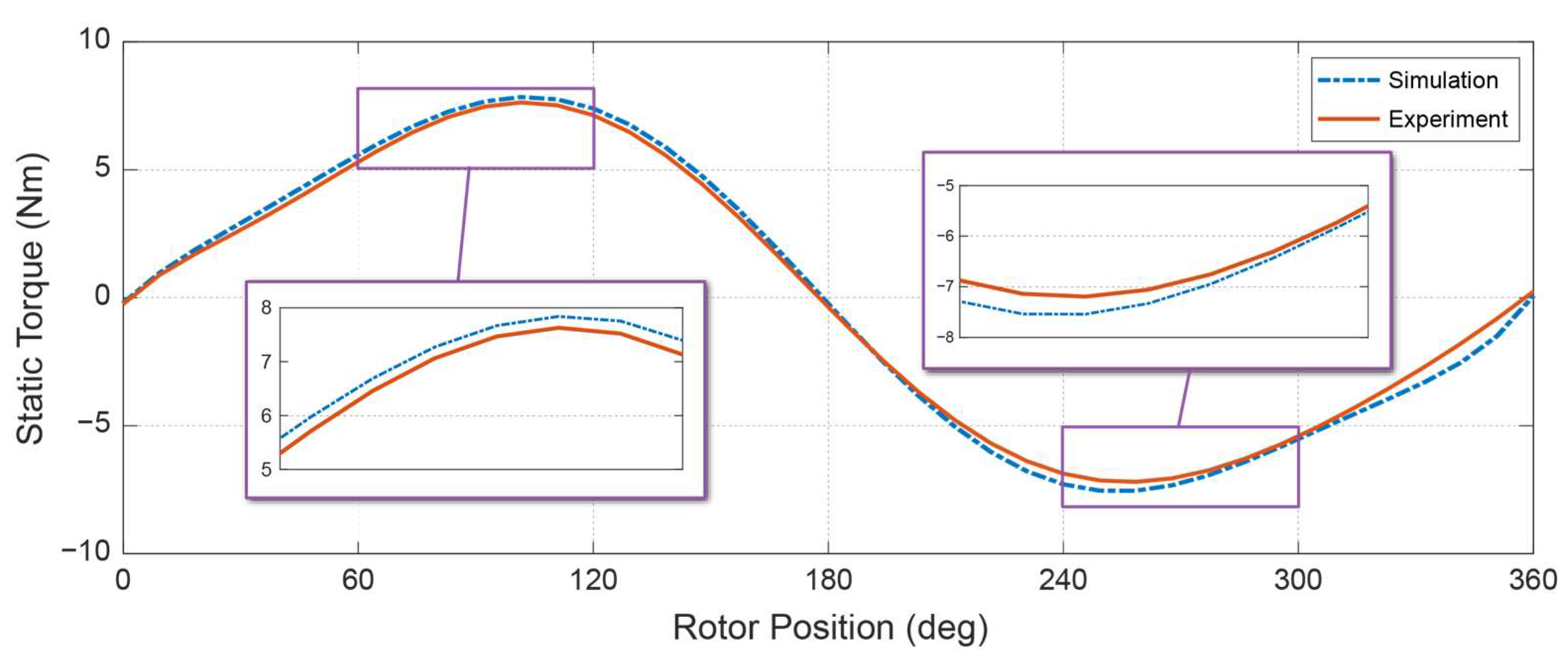
Using the servo as a load, the static torque of the motor was measured by applying a full load to the motor and rotating the rotor to obtain data for each rotor position. The results are displayed in
Figure 10. Although the experimental results fall slightly short of the simulation results, this is a common occurrence that is often due to uncalculated leakage flux and other losses. Nonetheless, the results indicate that the manufactured motor closely adheres to the design’s characteristics.
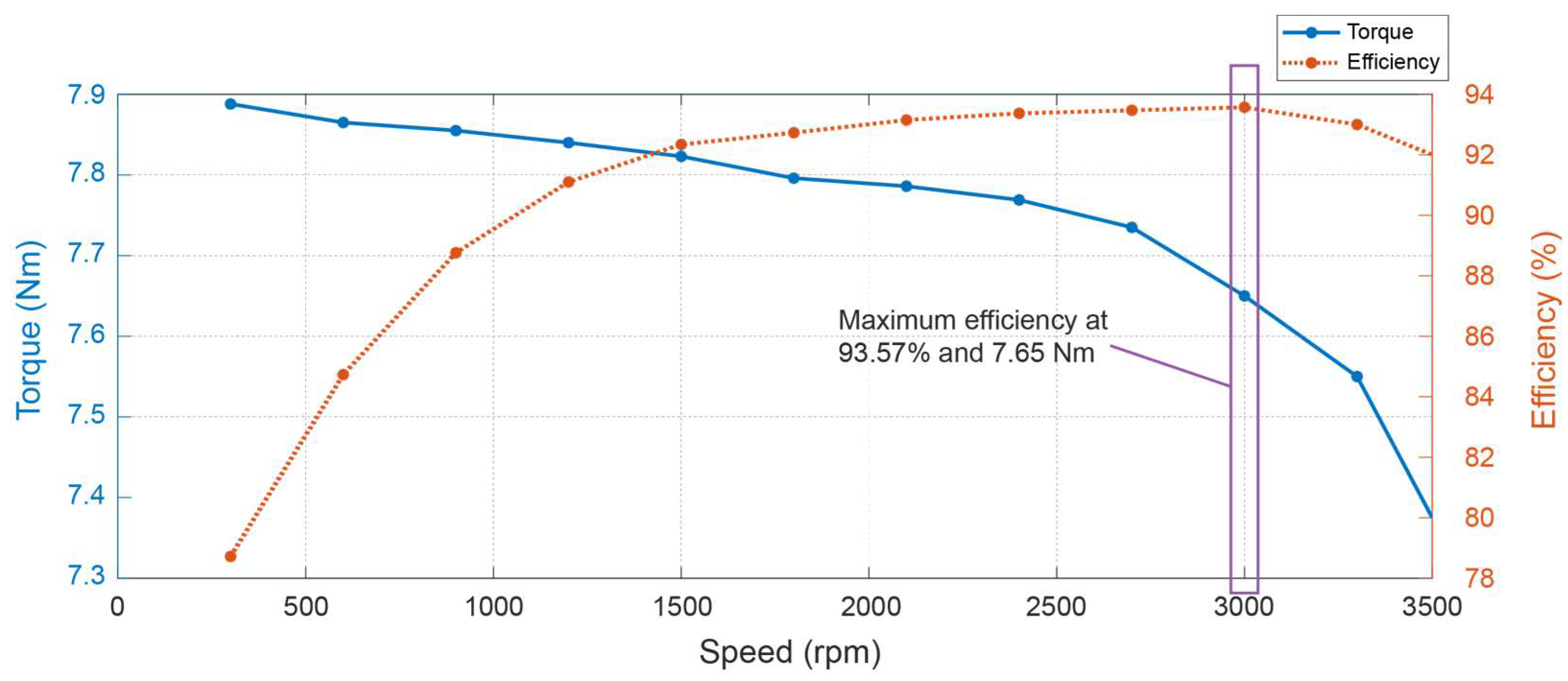
The torque and efficiency graphs of the motor are presented in
Figure 11. The proposed motor was originally designed with a rated speed and torque of 3000 RPM and 7.75 Nm, respectively. In
Section 5, the minor deviation observed between the design and experimental results is examined and addressed. The results indicate that the motor exhibits a highest efficiency of 93.57% at the rated point, which confirms that the manufactured motor aligns well with the original design. The calculated power factor is determined to be 0.74.
5. Discussions
In this study, a double air-gap PMSM configuration consisting of two stators and one rotor was proposed. While this structure offers the potential for higher power density due to the combination of two motors into one, its mechanical construction is notably complex. Additionally, the introduction of the magnetic screen, which was bonded using a special adhesive, further complicates the structure. The housing of this motor is more complicated compared to conventional motors and is susceptible to structural imbalances when connected to other components. Balancing issues were encountered during the experimental phase, requiring modifications to the bearing, shaft, and experimental setup. Eventually, the desired results, close to the simulation outcomes, were achieved after making necessary adjustments. The mechanical loss during the experiments was calculated to be 1.6% of the output power. As a result, it is not recommended to employ this structure in applications involving high power and/or high speed due to the associated complexities and challenges.
The design process of the proposed motor follows a similar approach to other double-stator PMSM designs. However, an important observation during the design process revealed that the outer and inner motors were not completely separated. This led to the idea of implementing a zig-zag magnet arrangement, which creates flux localization for each motor. Additionally, a magnetic screen was introduced as part of the design. In determining the appropriate values for inner parameters such as teeth height, air gap, etc., arbitrary values were initially selected, followed by a process of iteration and trial and error. This iterative approach allowed for refining the design and achieving the desired performance characteristics. Furthermore, it should be noted that further optimization can be undertaken to enhance the motor’s performance.
In terms of motor control, a commercial AC drive was employed for the experimental tests. The control setup involved adjusting the speed reference for both the AC drive and the servo motor acting as the load. It is important to note that no specific control method, other than speed control, was implemented during the experiment. It is worth mentioning that the availability of data for analysis was limited due to the constraints of the laboratory equipment. This limitation affected the extent of data that could be gathered and analyzed during the experiment.
It should be noted that achieving efficiency above 93% proved to be challenging during the experimental tests, primarily due to the limited rated power of the motor, which was set at 2.4 kW. In general, it is comparatively easier to attain higher efficiency in high-power applications, as the efficiency becomes less sensitive to power dissipated due to losses. In the case of the proposed motor, even a loss of 10 W can have a significant impact on the overall efficiency, affecting it by approximately 0.4%. This sensitivity to losses highlights the importance of careful design and optimization to minimize power dissipation and maximize efficiency. Throughout the design and prototyping process, multiple iterations and trial-and-error approaches were employed to refine and improve the motor’s performance. These efforts eventually led to the development of the final model and prototype motor, which demonstrated promising characteristics and closer alignment with the desired performance objectives.
It is recommended to conduct further analysis on the structural strength of the motor prior to finalizing the prototype. By performing a comprehensive structural analysis, potential weaknesses or areas of concern can be identified and addressed early in the design phase, reducing the need for extensive modifications in the final prototype. Additionally, during the manufacturing process, great attention should be given to the precise placement of PMs. Any slight misalignment or deviation from the intended design can have a significant impact on the overall performance of the motor. Therefore, strict quality control measures should be implemented to ensure the accurate and consistent placement of PMs. Furthermore, for vibration-sensitive applications or operations at higher speeds, it is essential to conduct vibration analysis.
6. Conclusions
In conclusion, this paper presented a novel dual-air-gap SPMSM with two stators and one rotor. The motor design incorporated a unique magnet arrangement in a zig-zag pattern, effectively isolating the outer stator and outer side rotor magnets from the inner ones. This arrangement created localized short flux paths for each outer and inner side of the motor.
To further enhance the isolation of the inner and outer rotor magnet flux, a magnetic screen was strategically inserted into the middle of the rotor core. This screen served to reduce core and magnet losses, resulting in improved motor efficiency. Although the proposed motor required a slightly higher current to achieve the same torque output, the losses were reduced by approximately 10%. Furthermore, the inclusion of the magnetic screen significantly reduced torque ripple by almost half, even with the same torque production.
Experimental testing of the proposed motor with the magnetic screen demonstrated a close match between the observed characteristics and the simulated results. These findings indicate that the proposed dual-air-gap SPMSM with a magnetic screen has the potential to enhance motor efficiency and reduce torque ripple in various applications.
