1. Introduction
In recent times, the electro-hydraulic servo valve, as a bridge connecting the electrical and hydraulic servo system, i.e., electro-hydraulic signal conversion and hydraulic amplifier, has the advantages of high control accuracy, fast response speed, high output power, flexible signal processing, etc., which is suitable for applications with a large load and fast response speed and has great development potential [
1,
2,
3]. Typical servo valves include flapper nozzle servo valves and jet pipe servo valves. The flapper nozzle servo valve has a fast dynamic response and small zero-level leakage, but its structure is complex and has poor contamination resistance with large zero-level leakage [
4]; compared to the flapper nozzle servo valve, the jet pipe servo valve has a higher resistance to contamination, but it has a larger zero leakage and the jet characteristics are not easy to predict [
5,
6].
Compared with the previous two, the newly developed two-dimensional (2D) servo valve has a small pilot leakage and is highly resistant to contamination, while having a certain self-cleaning capability [
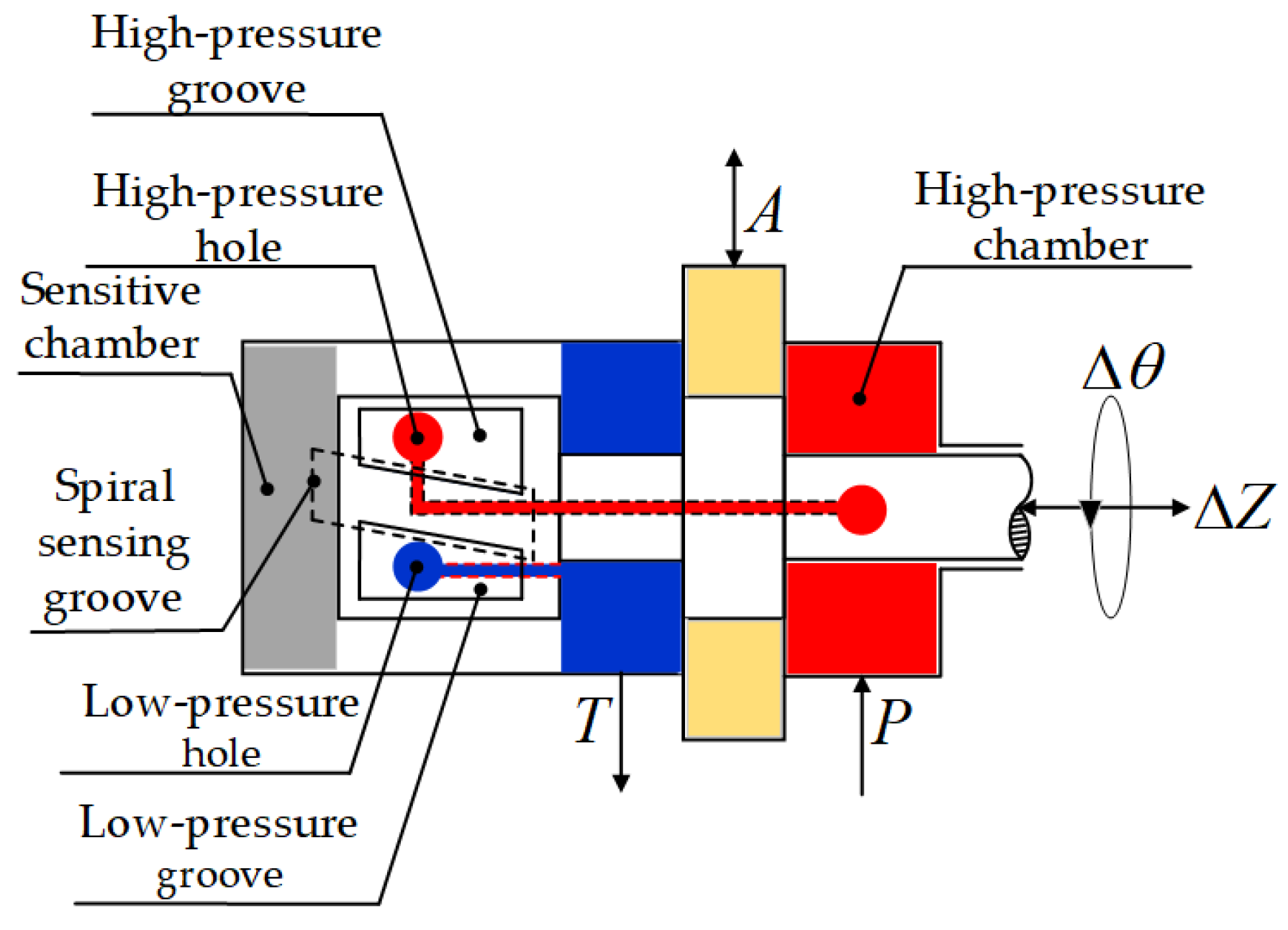
7]. The 2D valve is based on a hydraulic servo-spiral mechanism that allows the spool to achieve both axial horizontal movement and radial rotational motion of the spool, and its mechanism is shown in
Figure 1. The mechanism realizes 2D movement through the pressure servo principle, and has the characteristics of power amplification and position feedback, thus reducing the requirement for the output size of the electro-mechanical converter while ensuring the excellent performance of the servo valve [
8]. In order to realize the 2D movement of the servo-spiral mechanism, 2D servo valves often use proportional solenoids, stepper motors, and torque motors as their electro-mechanical converters [
9,
10].
The proportional solenoid has a compact structure with stable force-displacement characteristics and is easy to design as a multi-stage feedback proportional valve [
11]. Li et al. converted the linear displacement of the proportional solenoid into the angular displacement of the 2D valve spool by means of a compression-torsion coupling, so that the electro-hydraulic proportional directional valve spool produces axial displacement under the action of pressure differential in the sensitive cavity at both ends. When the system is under no pressure, the proportional solenoid will directly drive the spool axial movement to achieve proportional control, so as to realize the proportional control of a large flow rate and realize the operation under zero pilot pressure; however, it is large in size and low in frequency response, which is suitable for the large stroke and the control accuracy requirement is not high [
12]. Stepper motors are commonly used as digital interfaces for digital servo valves [
13], and Cui et al. used them to drive a high-flow 2D servo valve with closed-loop control of the rotor position using a space vector control algorithm through a position sensor to achieve flow control of the valve [
14], but stepper motors have the disadvantage of out-of-step, which will have serious consequences once they occur. There are also non-traditional electro-mechanical converters such as rotary electro-mechanical converters with self-negative feedback mechanism [
15] and linear force motors [
16], which are still in the experimental stage and have fewer cases for industrial applications.
The torque motor is currently the most widely used electro-mechanical converter for electro-hydraulic servo valves, which has the advantages of small size, fast response, and high resolution [
17,
18,
19]. However, in the design and research of wet-type motors, we found the following four main effects of the oil on the motor. The first problem is the effect of hydraulic fluid on motor heat dissipation. In order to ensure the performance and lifetime of a high-power motor, it is necessary to equip it with a heat-dissipation structure. To this end, the motor in [
20] used an external hydraulic pump for auxiliary heat dissipation and was equipped with cooling fins on the motor housing, but the cooling system, which accounts for most of the mass of the entire assembled motor, reduced the power density of the motor. The second problem is the damping effect of the oil. Jin et al. pointed out that although the oil-immersed structure could improve the heat dissipation performance, the fluid friction loss would also increase significantly due to the hydraulic oil in the air gap. For this reason, they proposed an accurate calculation method of motor oil friction loss based on CFD and analyzed the effect of air gap on oil friction loss, which guided the selection of air gap [
21]. The third is the problem of oil leakage. Liu et al. proposed a high-performance torque motor for a direct-drive valve, but due to the fragile structure of its motor-valve connection and the absence of oil circulation during operation, the valve will produce a large leakage when working at high frequency [
22]. The fourth is the problem of oil contamination. Metal contaminants in the fluid are usually generated by the work process and the hydraulic system itself; metal contaminants will make more obvious changes to the fluid conductivity, which can easily cause problems such as coil short circuits. Tu et al. proposed the oil contamination level quick monitor technique based on the mechanism of its electrical conductivity and developed the hydraulic oil contamination level monitor system [
23].
Based on the above studies, this paper presents a new type of 2D OTM, which not only has both rotation and direct movement but also can make the 2D servo valve adopt a cartridge structure to further improve its power density. The OTM has a separate wet-type working chamber with oil circulation flow channels for heat dissipation, and its coils are isolated from oil to prevent short circuits by oil contamination. The improved heat-dissipation capability allows higher operation current, thus improving the output torque and dynamic-static performance of the torque motor. The rest of this paper is organized as follows: in
Section 2, the configuration and working principle of the novel OTM are introduced. In
Section 3, the motion equations of the OTM are established based on the EMC method, which considers the effect of the leakage flux of the torque motor and the damping of the oil in the working chamber. In
Section 4, finite element simulation is used to verify the working principle of the OTM, and the influence of oil damping on the dynamic characteristics of the torque motor is analyzed by the numerical analysis software. In
Section 5, a prototype of the OTM is designed and manufactured, and special platforms are built to compare the prototype under two modes along with the CDTM. The experimental results are then compared with the analytical results and FEM simulation. In addition, the dynamic characteristics of the torque motor under different current conditions are compared between OTM and CDTM. Finally, some conclusions from this work are drawn in
Section 6.
2. Configuration and Working Principle
Torque motors can be divided into dry and immersed types according to their armature working environment. The dry types seal up the output parts to ensure stable working conditions, while the immersed types can allow the oil to enter the working chamber. When the coil is fed into the control current for a long time to generate much heat, the dry types generally use natural cooling; the immersed types can circulate the oil to take away the heat to achieve rapid heat dissipation. At the same time, the working air gap of the armature is small, and the oil instantly enters the working air gap to form an extruded oil film, which has a damping effect and can increase the damping ratio of the torque motor and improve the stability of the torque motor.
The designed novel OTM and its solid spool are shown in
Figure 2. The torque motor consists of eight parts, which are the connection block, the connection fork, the coil frame, the coil, the pole shoe, the permanent magnet (PM), the armature, and the flake spring. Since the components overlap with each other, this paper will describe their composition from the outside to the inside.
As shown in
Figure 2a, a pair of coil frames are placed on the right and left sides of the rectangular tab of the connection block to form a sealed working chamber; a pair of pole shoes are installed on the top and bottom sides of the coil frame; four rectangular permanent magnets are placed in the four empty slots formed by the upper and lower pole shoes; the PMs and the pole shoes are sucked together and clamped to the coil frame to make the overall structure tight and reliable; the coil frame has a groove on the outside for winding the control coil, avoiding contact between the coil with the oil in the working chamber while effectively transferring the coil heat to the oil.
As shown in
Figure 2b, the armature is located inside the working chamber; the connection fork passes through the inner bore of the connection block, and the two ends fit with the armature and spool, respectively, through the tooth groove, and the three are locked by screws to form the transmission assembly of the torque motor; the transmission assembly is fixed to the connection block by the flake spring, and the four elastic arms of the flake spring make the torque motor axially flexible so that it can realize double-degree of freedom rotation (shown by the red arrow in
Figure 2b) when the servo-spiral mechanism works. The spool is mounted on the connection fork and is compatible with the newly developed 2D direct-drive servo valve.
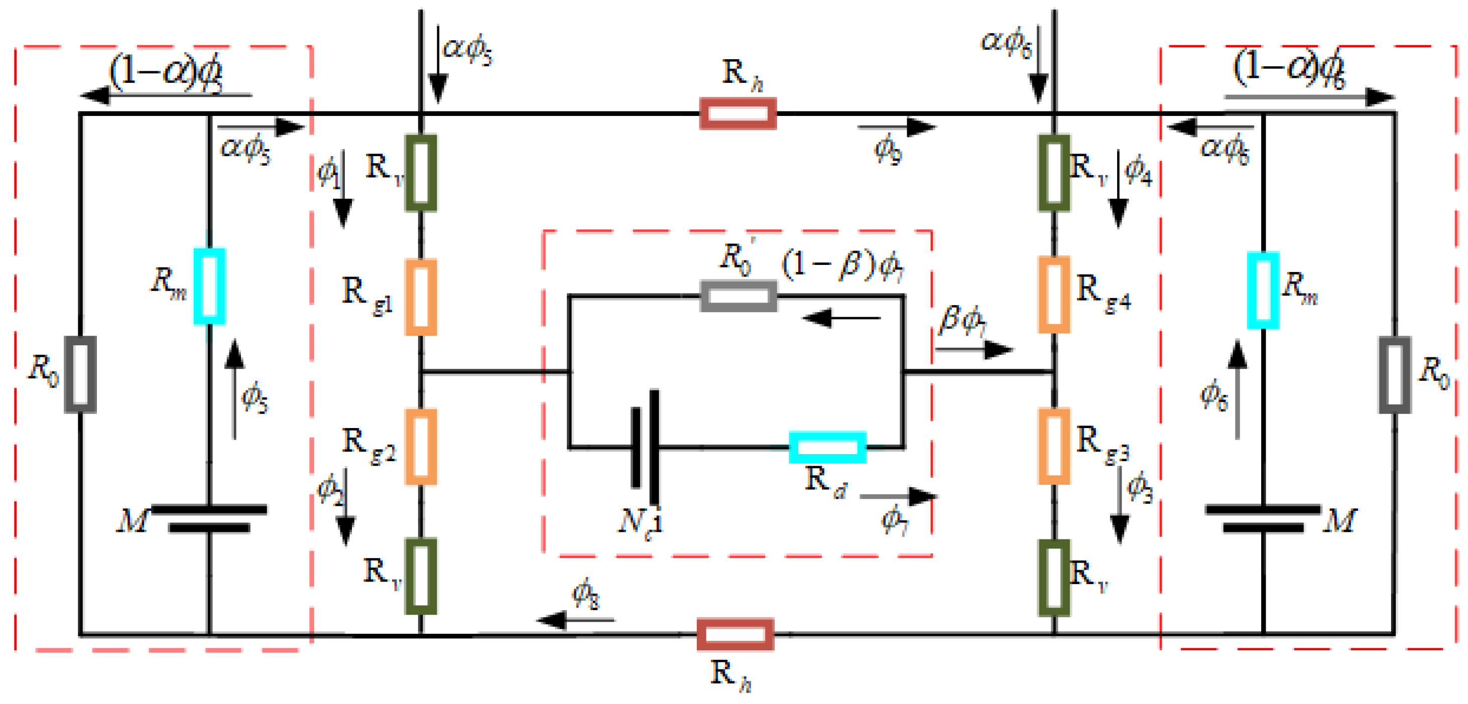
The working principle of the novel OTM is shown in
Figure 3, where the dual coils are connected in parallel due to the redundant design. When the coils are not energized, the length of the four air gaps are equal, so the armature is subject to equal magnetic suction, at this time the armature is in a balanced state of force, and the torque motor has no torque output. When coils are energized in the direction shown in
Figure 3, the polarized magnetic flux (blue line) generated by the PMs and the control magnetic flux (red line) generated by the control coils are superimposed on each other in the four working air gaps. The magnetic flux at air gap one and air gap four is enhanced, and the magnetic flux at air gap two and air gap three is weakened. Therefore, the electromagnetic suction force in air gap one and air gap four is greater than in air gap two and air gap three, and the armature will turn clockwise through a certain angle. Similarly, when the input current reverses the direction, the change of synthetic magnetic flux in the air gaps leads to counterclockwise rotation of the armature. When coils are de-energized, the connection fork and its fastened armature return to a balanced position by the action of the flake spring.
Generally speaking, the direction of output torque depends on the current direction, and the output frequency and amplitude can be changed by the frequency and magnitude of the current.
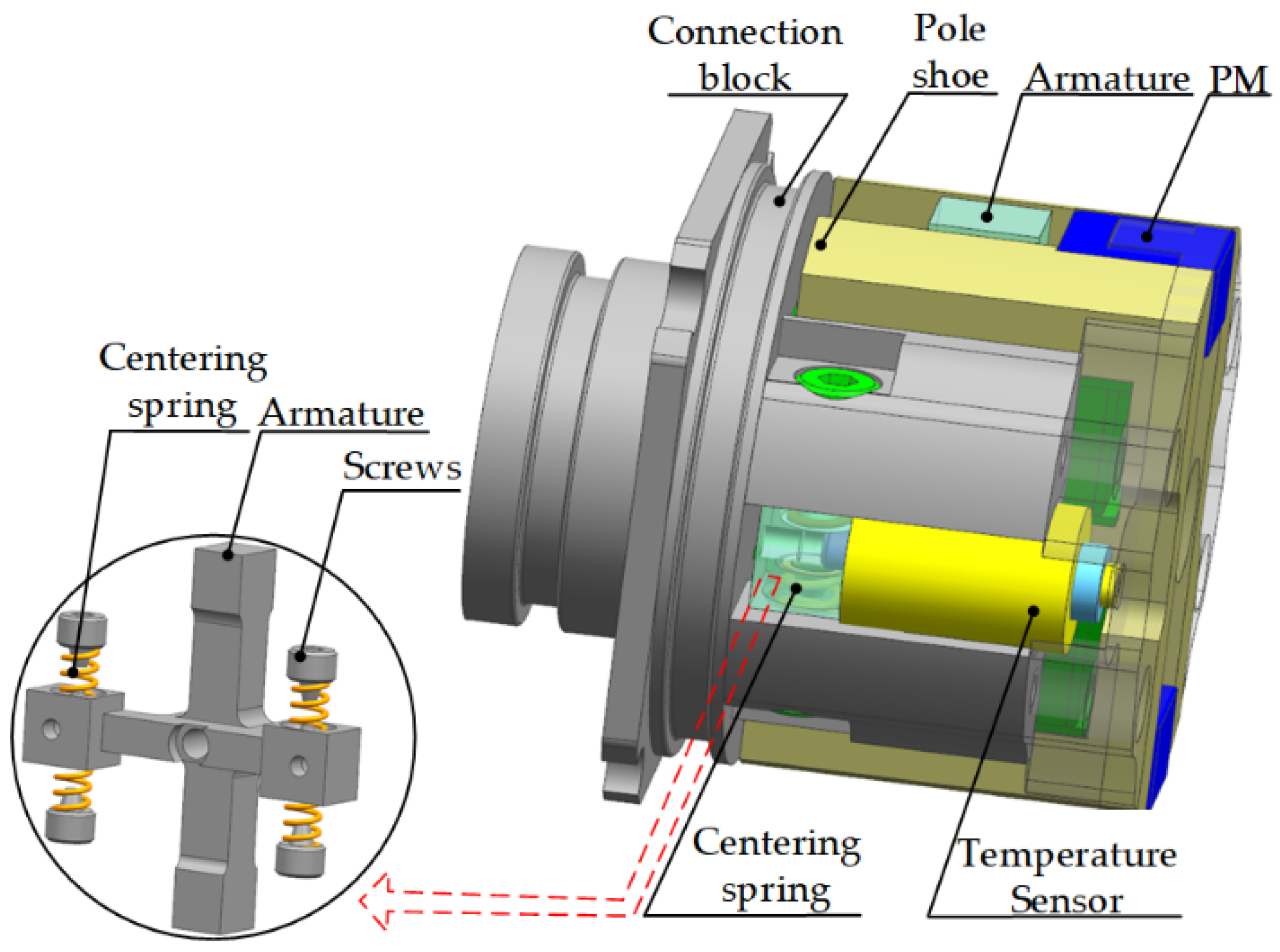
As the electro-mechanical converter of the servo valve, the accuracy and ease of their neutralization (alignment performance) of its armature alignment has a certain influence on the later assembly and performance of the servo valve. The selected CDTM is shown in
Figure 4, it consists of an armature, a connection block, two coils, two pole shoes, two PMs, and four springs. The motor has a similar mass and volume to OTM, and works by driving the armature through differential flux action. The torque motor differs from the OTM firstly in that it is designed as a dry-type, where the displayed part is isolated from the oil and exposed to the air, and secondly, as shown in
Figure 4, the CDTM has four holes in the armature for mounting the zeroing spring and the zeroing screw, which is adjusted to zero by adjusting the zeroing screw after the switching valve is assembled. This design reduces the cost, but makes the neutral position of the armature always on an unstable point, which cannot be maintained in practice and needs to be adjusted manually, with poor accuracy and difficult adjustment; the leaf spring located on the OTM has locking points in all directions, which can maintain the armature in the neutral position after installation. The differences between OTM and CDTM are shown in
Table 1.
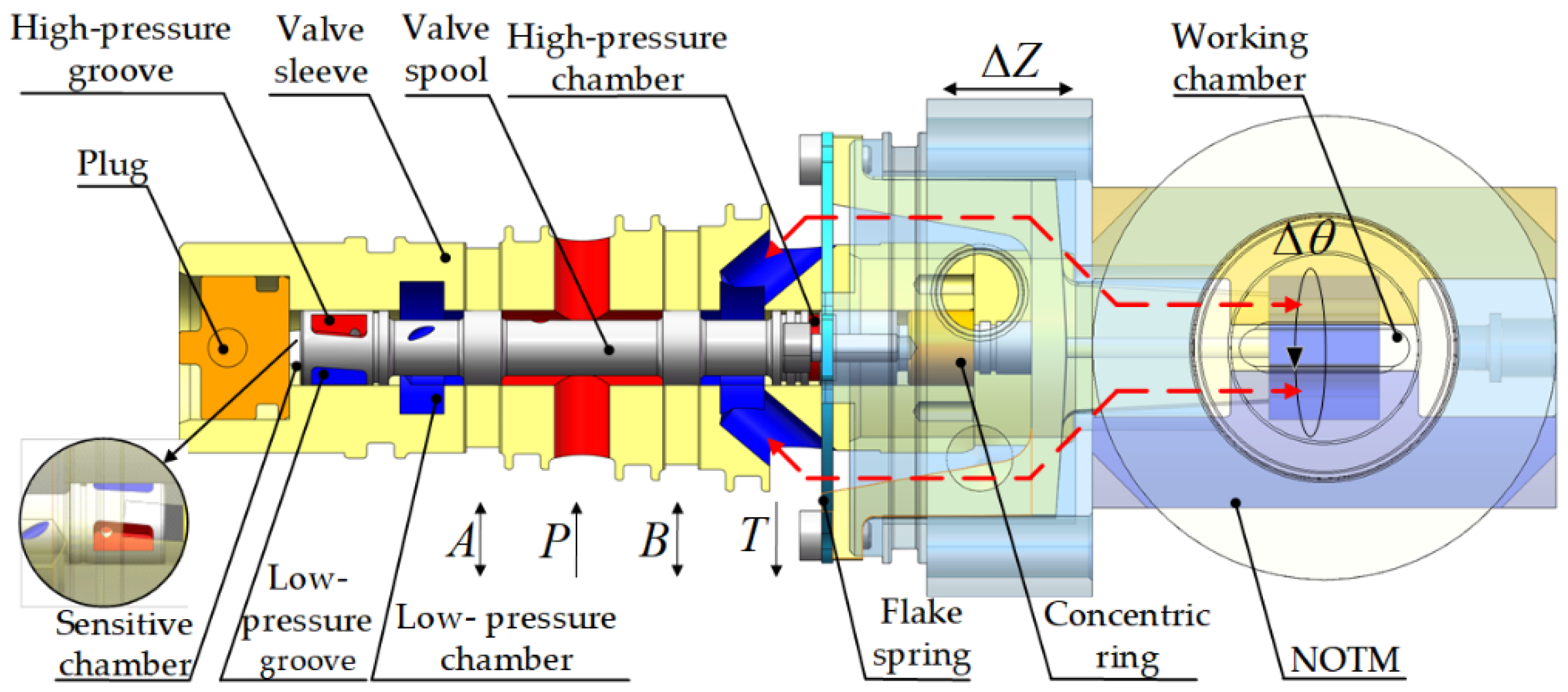
In addition, the new cartridge-type 2D valve based on the novel OTM is shown in
Figure 5. The oil flows in and out of the working chamber through the gap (red line) shown in
Figure 5, and continuously circulates to carry the heat generated by the control coil through the coil frame to the return port.
When there is no signal input, the pressure of the hydraulic servo-spiral mechanism is balanced, the valve is in axial force balance, and has no flow output. When coils are energized, the OTM outputs torque under the differential action of the polarized magnetic field generated by PMs and the control magnetic field generated by coils, which drives the spool of the valve connected to it to rotate synchronously. The overlap area of the high-pressure hole and low-pressure hole on the left side of the valve spool and the oblique groove on the valve sleeve changes, i.e., the sensitive chamber pressure changes, and the 2D valve force balance is disrupted, driving the main spool to axial displacement and output flow. The servo-spiral mechanism will interact between the circumferential rotation and axial movement, and there is a position feedback relationship between its rotation angle and axial displacement.
5. Experimental Study
To verify the accuracy of the theoretical and simulation analysis, an experiment of the OTM was conducted. After determining the materials and dimensions to be used, a prototype and experimental platforms can be constructed. The experiments in this paper are divided into four parts, including the temperature rise experiment, static characteristics experiment, dry dynamic characteristics experiment, and immersed dynamic characteristics experiment.
5.1. Design of Experiments
5.1.1. Design of Prototype
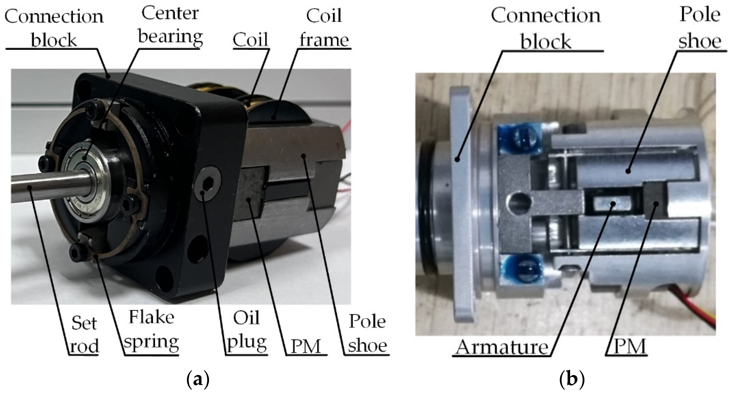
The prototype is shown in
Figure 13a. The novel OTM can be adjusted to work in both dry and immersed modes to control the variables. The OTM was considered to be in dry mode when the seals and oil plug were removed, it can be considered as a dry type torque motor with the same mass and power as the OTM, reducing test errors while controlling the variables. Before experimenting with the immersed mode, the coil frame, the oil plug, and the opening of each place were assembled with seals., and the resulting oil-immersed mode is shown in
Figure 13a. Ensure that the seal meets the criteria before experimenting, and then fill it with hydraulic fluid. The fluid used was No. 46 anti-wear hydraulic oil (L-HM46).
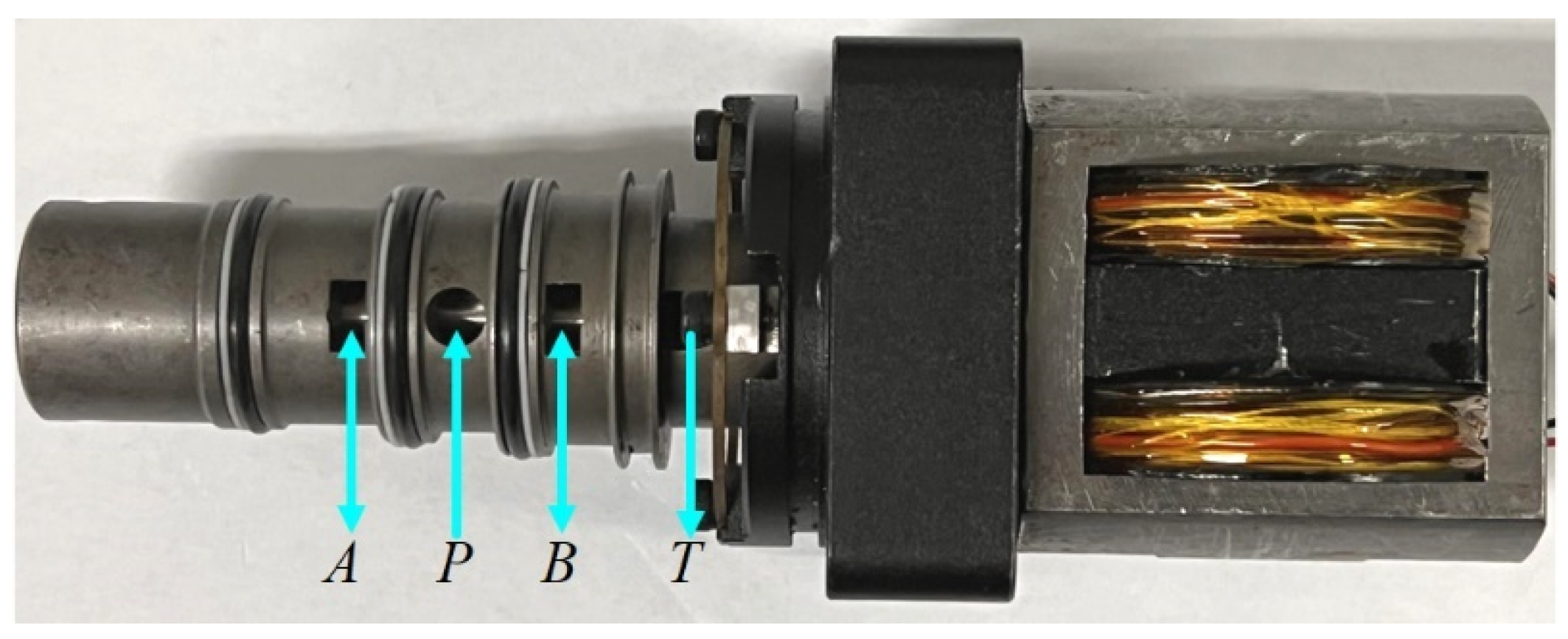
Figure 13b shows the CDTM used in the comparison experiment, which can share experimental platforms with OTM. In addition, the designed cartridge-type oil-immersed 2D servo valve is shown in
Figure 14. A and B can both be working ports, determined by the direction of hydraulic fluid flow; P is the pressure port to the hydraulic pump, while T is the return port to the tank.
5.1.2. Experimental Design of Temperature Rise
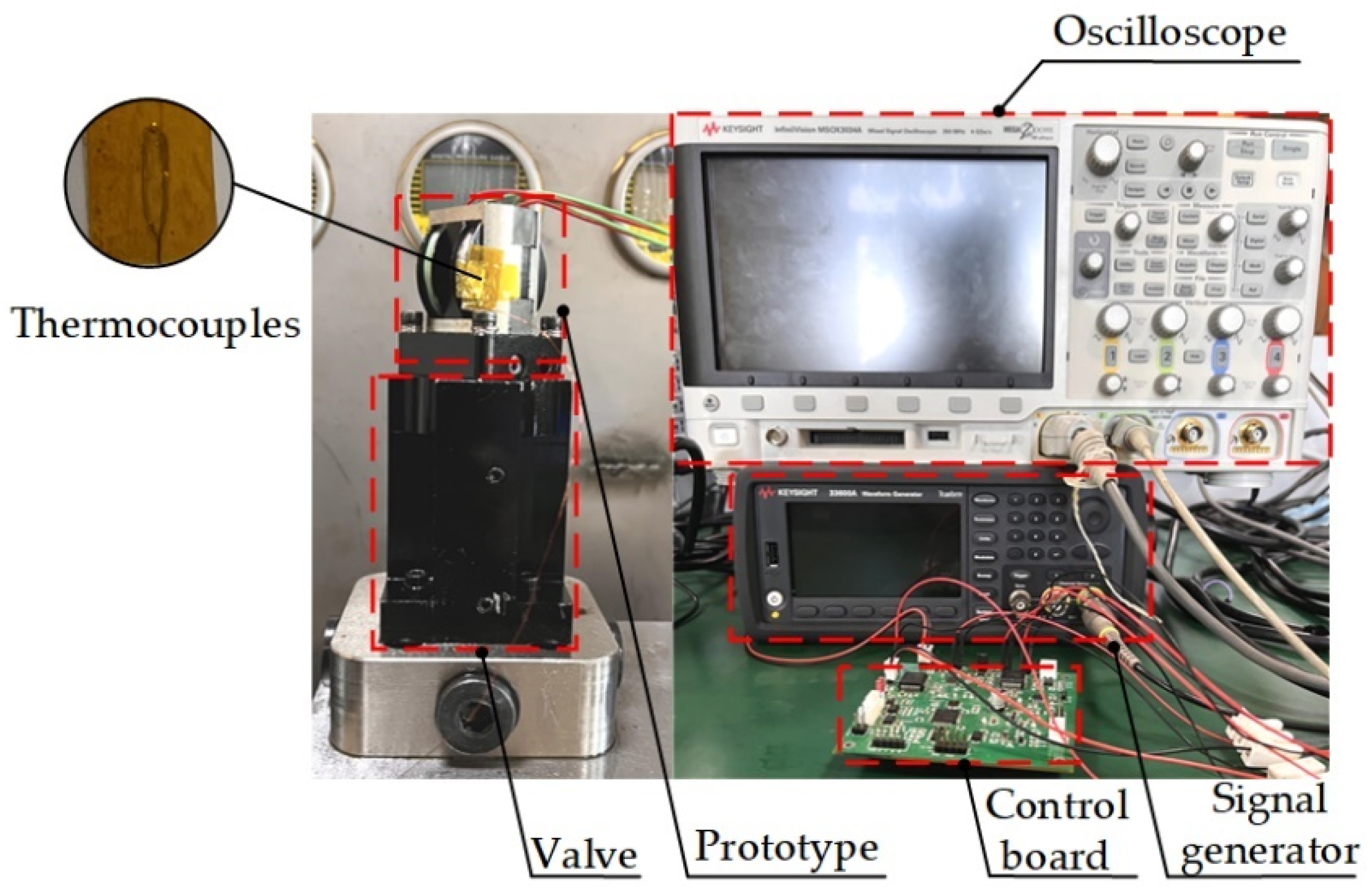
In order to experiment with the anti-thermal performance of the novel OTM without changing the environmental variables, and to demonstrate the difference from a CDTM, the temperature experimental platform was designed as shown in
Figure 15.
Connect the 2D servo valve in an open oil circuit and install temperature sensors on its coil frame. In order to meet the width of the coil frame and provide sufficient output torque, both motors’ coil wire diameter was 0.3 mm2, 400 turns. The theoretical rated current of the coil was about 2.4 A, and the safe temperature for long-time use was 65 degrees. In order to maximize the copper consumption of the coil and the iron consumption of the armature while ensuring safety, the control board was made to output sine signals of different amplitudes at 80 Hz. The temperature generated by the coil was transmitted back to the oscilloscope by the temperature sensor, and the input amplitude was continuously adjusted to reach a safe temperature (about 65 °C). Each coil was cooled to room temperature after the experiment before the second experiment. Temperature experiments were divided into three groups:
(1) Dry scheme. Close A and B ports on the valve before the experiment, with no oil in the valve;
(2) Wet scheme. Adjust the system pressure to 7 Mpa while the A and B ports are open, so that the working chamber is filled with fluid circulating with the external domain;
(3) Separate testing of CDTM.
5.1.3. Dynamic and Static Characteristics Test Bench
In the construction of the dynamic and static characteristics experimental platform, because the prototype’s rotational inertia, output torque, and armature displacement were small, and the experiment input frequency range was wide, in order to obtain more accurate displacement results, a non-contact displacement sensor was required. According to the requirements, the designed experimental platforms are shown in
Figure 16.
Experimental platforms were mainly composed of adjustable DC power source, programmable power source, high-precision current sensor, torque sensor, hall sensor, and laser displacement sensor. The high-precision laser displacement sensor had a repeatability of 0.5 μs and a measurement frequency of 50 kHz. The programmable low-noise power source provided different input sine or square wave signals, which were collected by the current sensor and reflected on the oscilloscope. The torque motor output torque was sent from the torque sensor to the oscilloscope, as shown in
Figure 16a; the displacement signal was transmitted from the laser displacement sensor to the oscilloscope and converted to angular displacement, and flux changes between the air gaps were detected by Hall sensors and displayed on a Gauss meter, as shown in
Figure 16b.
5.2. The Thermal Performance of the Prototype
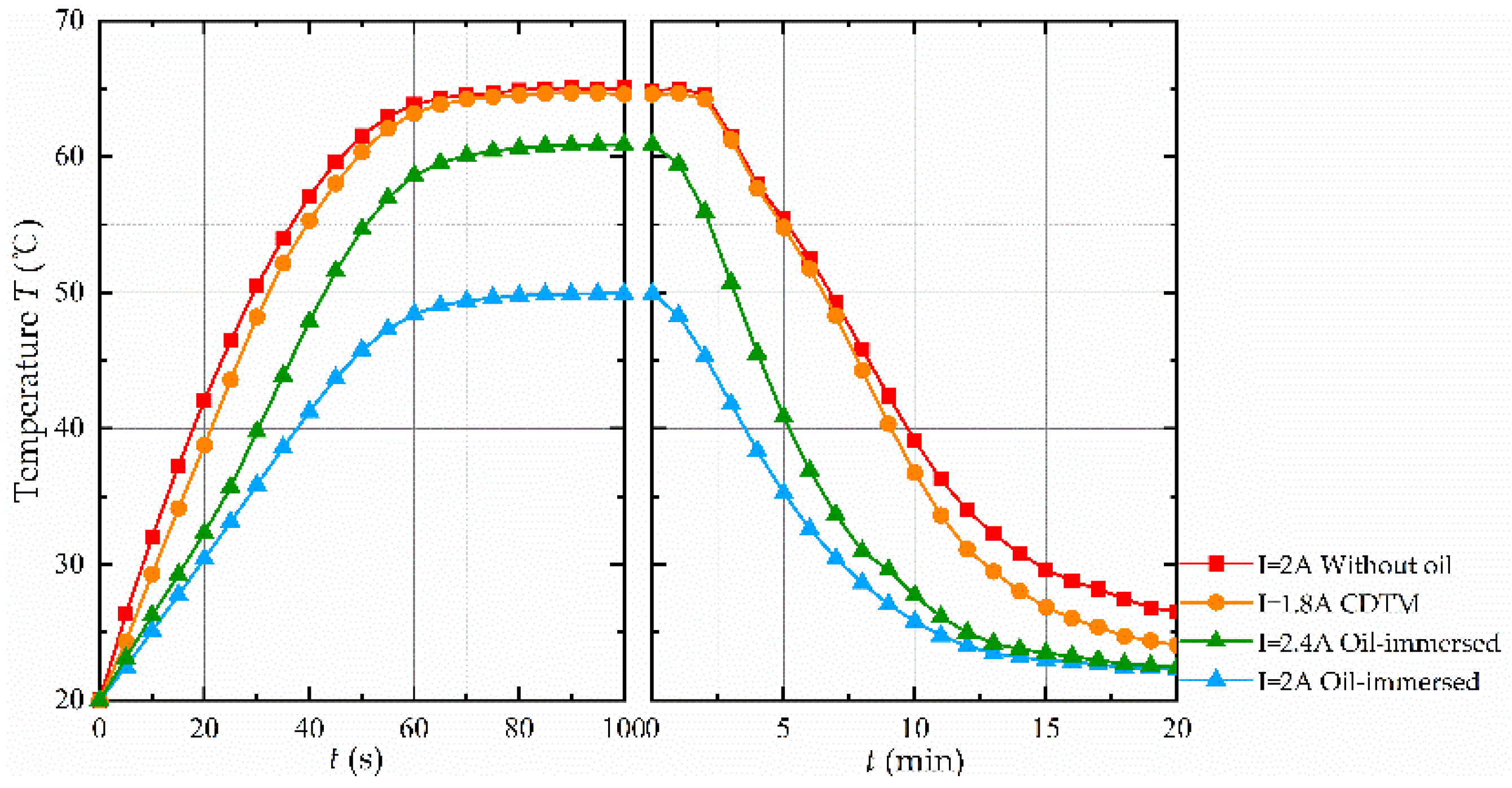
Figure 17 shows the results of the temperature experiment, and for the sake of uniformity of calculation, the time for the coil frame to reach 90% of its final temperature is referred to as its rise/fall time. It can be observed that when the 2 A control current was applied to the prototype, the coil temperature of the dry mode rose rapidly, with a rise time of about 43 s, and its final temperature was close to the safety temperature; the situation was similar for CDTM, whose coils were close to the limit temperature when the current was 1.8 A. While the temperature of the immersed mode rose slowly, with a rise time of about 49 s, the final temperature was about 15 degrees less than the dry mode, with a temperature reduction of about 13%.
When coils were de-energized, the two sets of curves with oil circulation were observed; the heat in the coil was taken away by the oil and returned to normal temperature in about 14 min; while the dry mode caused no significant temperature drop in the first three minutes due to the continuous heat accumulation in the coil, and the subsequent temperature drop was also slow. The same occurred with the CDTM, where the coil temperature dropped slightly faster than the OTM’s dry mode, but there was still a heat dissipation lag. It is worth mentioning that the oil was heated due to the work of the coil and the pump station, resulting in the final temperature of the experiment not being the initial room temperature but the oil temperature that had risen slightly after heating, while the dry scheme was unable to bring the coils to the average oil temperature level in the end.
For the temperature in immersed mode had not yet reached the upper limit of the working temperature of the coil, debugging the control current to 2.4 A, the coil temperature to the upper limit of safety, compared with the upper limit of the dry mode current was about 21.3% higher, the rise time was about 50 s, and the final temperature was about 61 degrees; when the coil was powered off, the accumulation of heat was not obvious and its fall time was about 14 min.
5.3. Dynamic and Static Characteristics of the Novel OTM
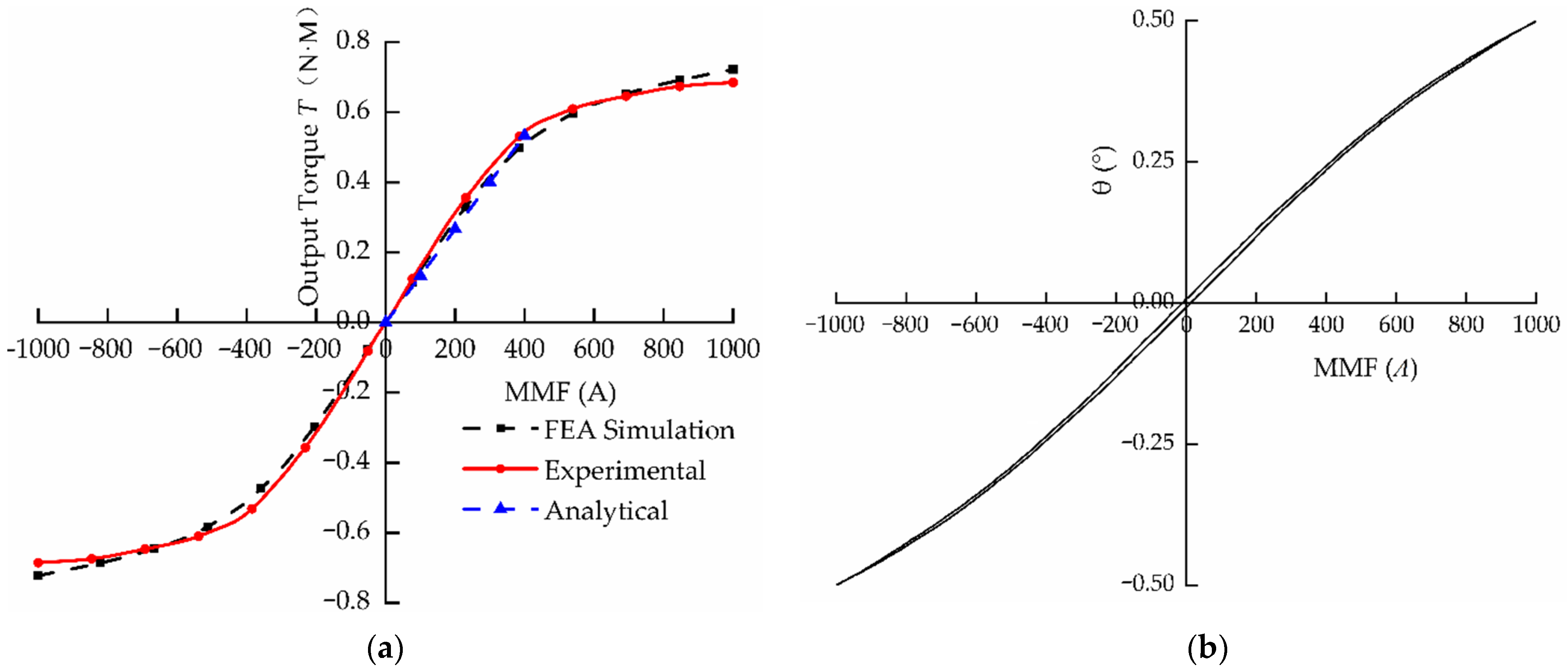
Figure 18 shows the static characteristics of OTM. When the armature was in the neutral position, the relationship between the coil MMF and output torque was as shown in
Figure 18a.
The output torque linearity of the torque motor was quite good at 0–1.125 A, the experimental results were in good agreement with the simulation results and analytical results. After 1.5 A, the output torque rose slowly due to the gradual magnetic saturation.
Figure 18b shows that the hysteresis loop of the torque motor was about 2.53%, and the linearity was 3.36% at 0–1 A, which is in accordance with the design index of the torque motor. The nonlinearity in the second half of the curve was due to the closed-loop control of angular displacement and velocity that was not added during the experiment.
Figure 18c,d shows the comparison results of analytical, FEA simulation and experimental results of the the magnetic flux densities in air gap one and air gap two, and it can be observed that the three sets of data were in better agreement in the range of −230–230 A. When the input current gradually increased, the FEA model was similar to the experimental results, due to the armature and pole shoe entering progressive saturation.
Table 4 shows the comparison of the static characteristics of the OTM and CDTM. It can be seen that the static characteristics of the OTM with 4 magnets installed were better than those of the CDTM with 2 magnets due to the simplified combination structure.
Figure 19 and
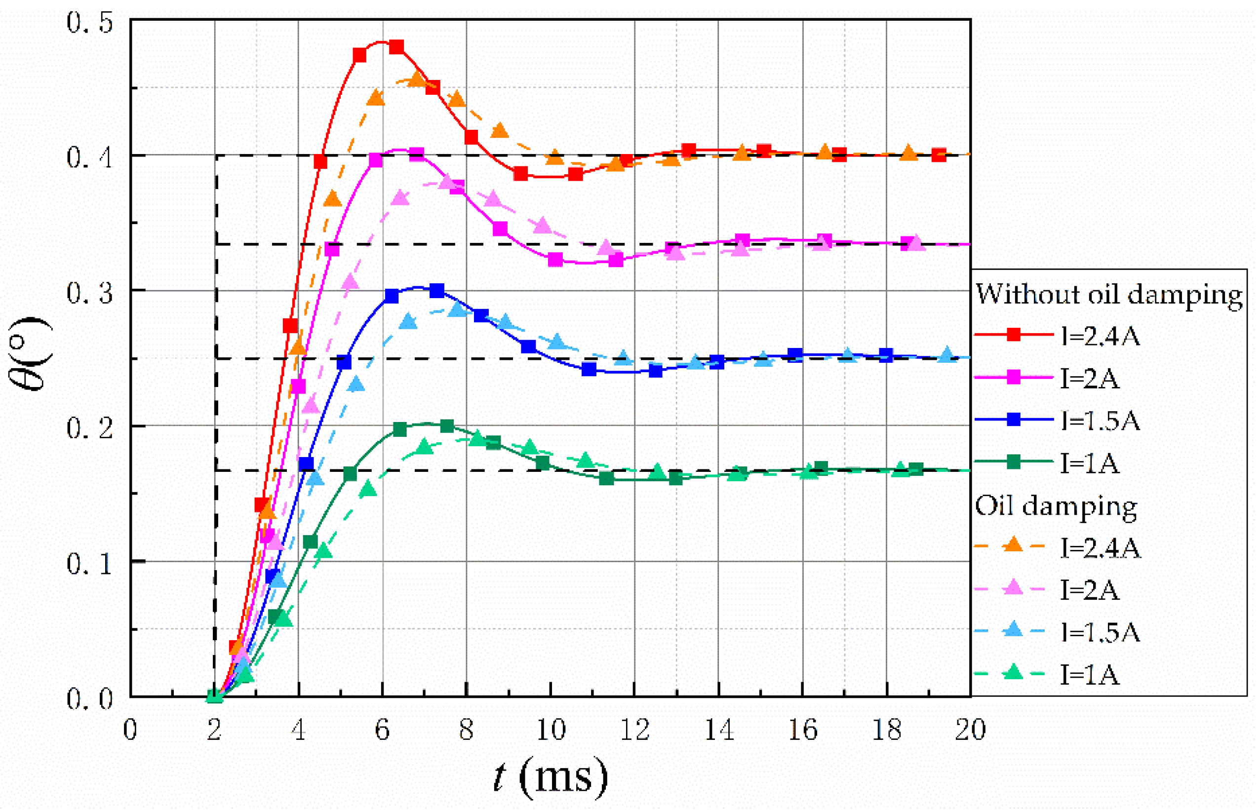
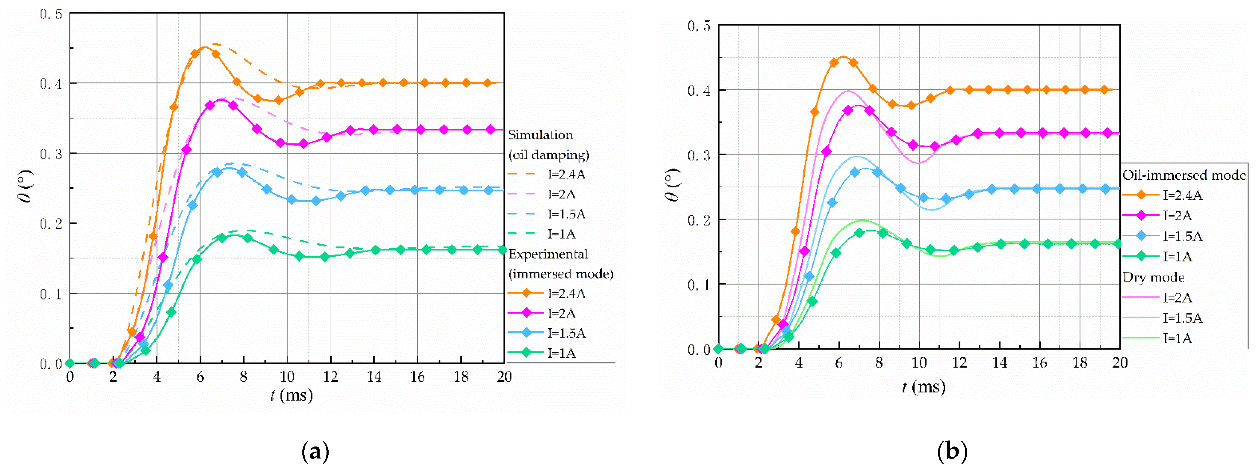
Figure 20 show the dynamic characteristics of OTM. Since the limit current that OTM can pass in dry mode was measured during the temperature rise experiment, the maximum current in dry mode during the experiment was 2 A. The step response curves for the two modes at different currents are presented in
Figure 19. It can be observed that, under the same control current, the step time is slightly slower than the dry mode due to the increase in system damping after filling the oil, but the percentage overshoot and adjustment time were simultaneously reduced compared with the dry mode. The experimental results were similar to the simulation results, and the analysis demonstrated that the oil-immersed mode increased the damping ratio and the stability of the system.
The step response data are shown in
Table 5. In the rated current range, as the current increased, the step response of the torque motor became better; if the control current was increased by 17% or more, the response speed of the immersed mode was faster than that of the dry mode. Due to the influence of heat dissipation, the control coil of the dry torque motor could only pass a maximum current of about 2 A, and the step response of the torque motor could only be as fast as 2.84 ms. With the oil-immersed structure, the heat dissipation was improved, and the control coil could be fed with a larger control current, which could reach 2.4 A. At this time, the step response of the torque motor could reach 2.71 ms, the percentage overshoot was reduced by 7.1%, and the adjustment time to a steady state was approximately 8.5% faster. It indicates that the torque motor was more stable in immersed mode. Meanwhile, it can be observed in
Table 5 that OTM was higher than CDTM in terms of allowable through-current, step response speed, and stability.
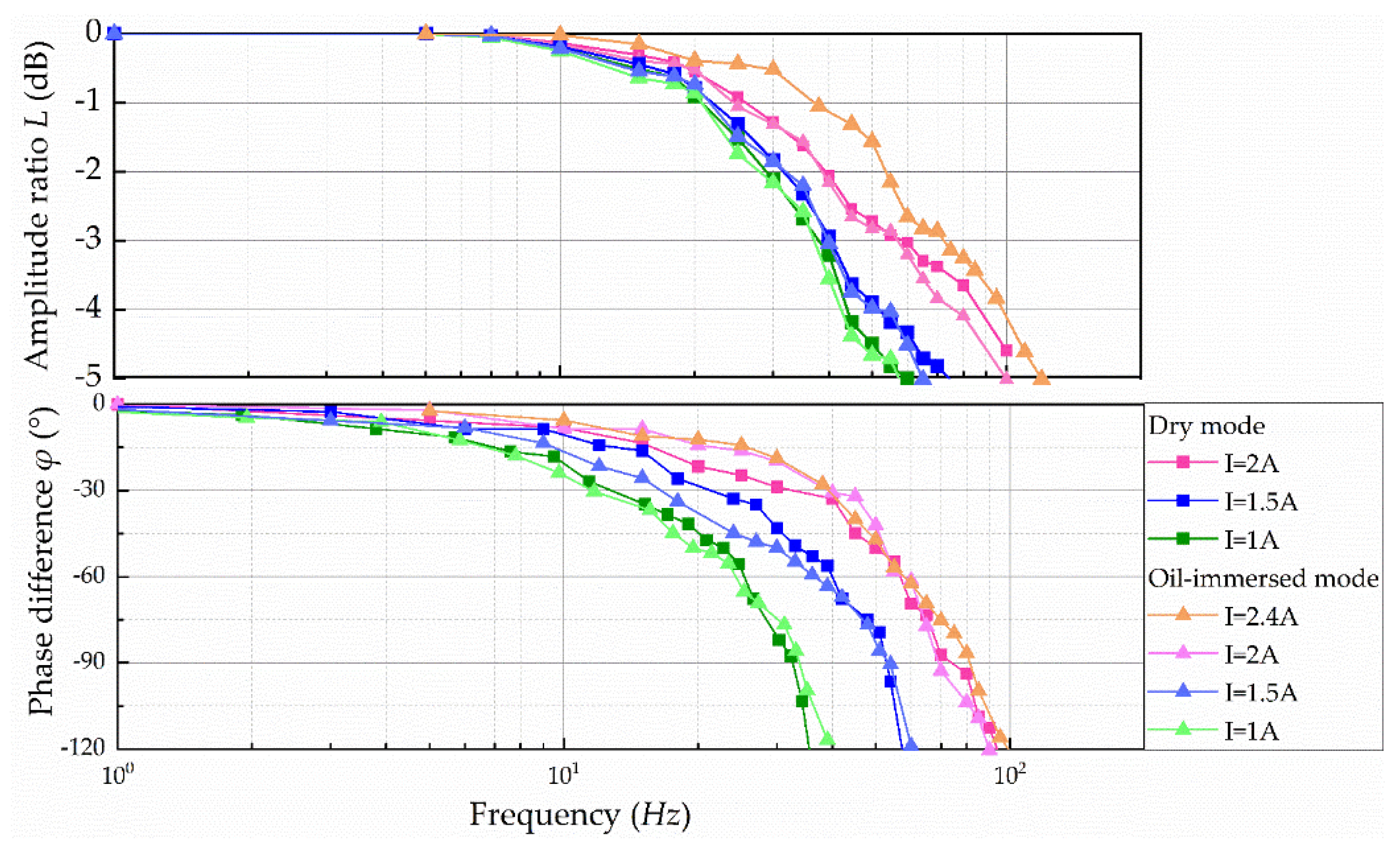
It can be observed in
Figure 20 that the prototype followed the input signal better at lower sinusoidal input frequencies, further verifying that the OTM had good static characteristics. As the frequency of the sinusoidal input signal increased, the output amplitude of the OTM gradually decayed with phase lag.
Therefore, when the control currents were the same, the oil-immersed mode and dry mode showed consistency in frequency characteristics, indicating that increasing the oil damping did not have a major impact on the high-frequency operation. Comparing the currents between different groups, it was evident that the frequency width increased with the increase in the control current. Similar to the step response results, the torque motor bandwidth can be increased by about 17.8% due to the higher current that the wet mode can withstand. The amplitude-frequency characteristics in the low frequency corresponding to the bandwidth were similar to the results of the simulation, but the hysteresis was more serious at high frequency, and this phenomenon may have been caused by the static friction between the connection block and the connection fork. By comparing and analyzing the data of OTM and CDTM in
Table 6, we can deduce that OTM showed better amplitude frequency and phase frequency characteristics under high currents; also its performance of two modes at rated current is better than CDTM.
6. Conclusions
(1) This paper presented a novel configuration of an oil-immersed torque motor. To meet the oil-immersed structure, the coil frame was combined with the working air gap to isolate the coil from the oil. At the same time, the permanent magnet suction made the structure firm and compact, and the parts utilization rate was higher than the CDTM and easy to process and assemble. In addition, the structure can also move in two dimensions and can be connected to a spool to become a simple 2D servo valve. The experimental results showed that the prototype had good linearity of current-torque characteristics within 1 A, with a maximum output torque of about 0.7 Nm, which is suitable as an electro-mechanical converter for electro-hydraulic servo valves.
(2) An equivalent magnetic circuit model and equations of motion for the novel OTM were developed. The equations incorporated the magnetic leakage effect and the oil-damping effect into the calculation. The analysis results, simulation results, and experiment results were in good agreement, indicating that the model can accurately predict the dynamic and static characteristics of the OTM.
(3) Under the same size and mass of the system, the heat of the immersed mode of torque motor was taken away by oil circulation, compared with the dry mode and the CDTM. It was found that the heat dissipation performance significantly increased, the coil could load larger current, the step response characteristics and amplitude characteristics were better; at the same time, due to the increase in damping ratio, the step response overshoot was smaller compared with the dry mode, and the adjustment time was faster. Therefore, for valves with a good resistance to contamination and, at the same time, a higher power, the immersed type of the electro-mechanical converter is more worth considering than the dry type.
