Abstract
This article deals with the problem of loose materials, i.e., wheat grain, when transported by belt conveyors with cover belts. For the purpose of further research, experimental measurements of the deflections of a conveyor belt with loose material were carried out on a self-built laboratory test device. The mechanical contact between the wheat and the belt could be suitably approximated using an elastic foundation. The measured data were evaluated and used to obtain functional relationships for the compressibility moduli of the bilateral Winkler elastic foundation. The obtained relationships were further stochastically processed using the Monte Carlo method.
1. Introduction
1.1. Belt Conveyors
Material handling is defined in the Czech Republic (and similarly in other countries of the world) within the standard ČSN 260002 [1] as the professional movement, loading and directing of materials (objects) in production, circulation and storage. A handling system is defined as a set of two or more handling devices and means of transport, forming an interconnected whole of a particular area of transport, management and organisation.
According to ČSN ISO 7149 [2], a belt conveyor is defined as a conveyor (or feeder) for free bulk materials (loose materials) or individual loads, with an endless conveyor belt (made of rubber, textile, steel, plastic, wire, etc.) as a supporting element.
A belt conveyor is a mechanical conveyor with a pulling and carrying element in the form of an endless belt guided and driven by drums [3]; the conveyor belt is supported along the length of the conveying route by rollers or a flat surface on which the pulling and carrying element (conveyor belt) is guided by friction. The belt conveyor is suitable for conveying both loose and solid materials in horizontal, inclined [4] and, with special modifications, steep and vertical directions.
Currently, the terminology and classification of conveyors transporting materials at high angles of inclination is not precisely defined. Steep conveyors are considered to be all conveyor designs intended for conveying loose and solid materials at angles exceeding the maximum (critical) angle at which the conveyed material is distributed on the conveyor belt surface and without initiating reciprocating motion relative to the belt due to gravitational forces. Steep and vertical conveyors are best classified according to the structural and functional characteristics of the equipment which ensure that the conveyed material remains on the conveyor belt.
In order to increase the permissible angle of inclination of the conveyor, it is necessary to:
- -
- Increase the coefficient of friction between the conveyor belt and the conveyed material;
- -
- Structurally modify the surface of the conveyor belt so that the relative movement of the conveyed grains along the belt is prevented [5] (in the case of either inward transport against the direction of belt movement, or downward transport in the direction of conveyor belt movement); and
- -
- Increase the pressure of the conveyed material on the conveyor belt [6].
Increasing the critical angle of inclination of a conveyor belt of conventional design can be achieved by means of an additional, so-called “cover belt”, which is routed parallel to the carrier belt [7], see Figure 1.
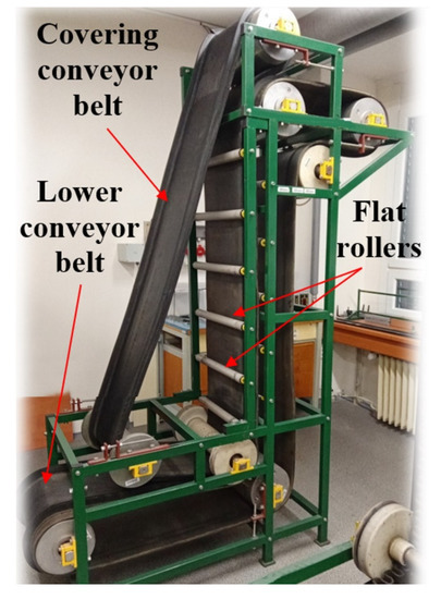
Figure 1.
Sandwich belt conveyor.
The cover belt creates the necessary pressure on the material by its own weight, increasing its adhesion and cohesion to the supporting conveyor belt. Depending on the type of conveyor belt selected and the pressure devices used, these conveyors are capable of conveying loose material at inclination angles significantly exceeding the critical inclination angles of conveyor belts of conventional construction.
The advantages of belt conveyors with a cover belt are the possibility of transporting loose material under inclination angles of up to 90° at high transport speeds reaching up to 6 m/s, independent of transport performance on the inclination angle of transport; and the possibility of hermetic transport of loose materials [8], which is of specific importance in the transport of dusty and toxic materials. The disadvantages of belt conveyors with a cover belt are the often higher construction complexity, increased wear of conveyor belts, and higher energy consumption compared with belt conveyors of conventional construction.
The necessary increase in the normal pressure of loose material against the supporting branch of the conveyor belt is achieved by pressure elements, e.g., [6]. Special belts are used as pressure elements—which either consist of chains with circular or elliptical links, or are conventional rubber conveyor belts—which are pressed by a series of movable attached pressure rollers [7] placed at a given distance, and also by means of pneumatic and magnetic devices.
The pressure devices of the conveyor belts of belt conveyors which use a cover belt consisting of link chains are suitable for the transport of loose materials of larger grain size. Pressing devices consisting of conventional rubber conveyor belts are suitable for homogeneous, fine-grained loose materials which are usually loaded onto the conveyor belt in a uniform layer.
The design of belt conveyors with cover belts is based on different ways of increasing the normal friction of the conveyed loose material against the supporting conveyor belt. The principles of increasing friction are achieved by using:
- -
- The weight of the conveyor belt;
- -
- Exertion of external pressure forces by means of spring-loaded rollers;
- -
- Elasticated air-filled bags, and
- -
- Magnetic forces in the transport of ferromagnetic as well as non-magnetic materials.
The transport of loose materials by vertical belt conveyors with cover belts is realised in a slot formed by the carrier and cover belt [7], which in parallel lead (at a given distance) in the direction of their longitudinal axis at the same speed along the vertical part of the transport route. Depending on the geometric dimensions of the slot, the height of the column of the conveyed loose material, the mechanical–physical properties of the conveyed material, and the strength properties and pre-stressing of the conveyor belt, deflections of the conveyor belt can occur during the conveying of the loose material through the vertical conveying shaft. The amount of deflection of the conveyor belt depends, in addition to the above parameters, on the spacing and arrangement (opposing or staggered) of the pressure rollers. Belt conveyors with cover belts adapted for steep conveying of bulk materials (up to conveyor inclination angle max. 60°), use a cover (pressure) conveyor belt, which is laid on a layer of loose material, to transport materials at inclination angles exceeding the limiting inclination angles of belt conveyors of standard construction. As a result of the pressure exerted by the weight of the cover conveyor belt, the pressure of the conveyed material against the carrier belt increases, thus increasing the frictional force in the contact area of the carrier conveyor belt (the size of the frictional force is a function of the normal force) and the limiting angle of inclination of the conveyor.
1.2. Loose Materials
Based on their origin, loose materials are divided into natural (inorganic and organic) and artificial (based on inorganic, organic or combined raw materials).
Loose materials [9] are also classified according to their physical and chemical properties. Among the basic physical properties are those sufficient to determine the weight and dimensions or volume of the material sample under test. These material properties are in particular: specific weight, density, porosity, moisture content and grain size. The chemical properties of substances are defined by the ability of substances to react in chemical reactions.
A classification of loose materials has been developed by the international organisation “Fédération Européenne de la Manutention”, according to which loose materials are characterised by grain size, cohesion, behaviour during transport, volumetric mass and temperature.
The mechanical behaviour of a loose material is a complex reflection of its structure, i.e., the essentially random nature of the motion of each particle. The mobility of the particles of a loose material is the reason why, unlike solid, continuous substances (a continuum consisting of solid particles), the state of a loose material changes, even within relatively narrow limits. The following mechanical properties of loose material are important parameters: grain size; moisture content; loose grain weight; loose grain angle; internal and external friction angle; cohesive stress and stress state. More information about the properties of loose materials can be found in [9,10].
1.3. Solved Problem
The compression of the belts between which the loose material is placed is a key parameter when transporting material at high inclination angles. For this reason, the paper focuses on the interaction of the carrier and cover belt with the loose material, which are wheat caryopses. For the purpose of research and development of sandwich belt conveyors, a laboratory device for measuring the belt deflection of a belt conveyor with loose material was created.
The obtained results of the measured deflections were used for a simple analytical model of the elastic foundation according to Winkler. For further practical use, the results were also processed stochastically, i.e., probabilistically, using the Monte Carlo method. The obtained stiffness values of the elastic foundation, which are random in nature, could be applied in engineering practice, e.g., engineering design and material transport.
The application of an elastic foundation in connection with loose materials, a stochastic approach and belt conveyors, is a novel methodology.
Our article is focused on the interaction between conveyor belt and grain wheat free of bran. However, the presented methodology (derived equations, measurements and their evaluation) can be used even for different types of loose materials, e.g., sand, gravel, soil, flour, etc.
2. Materials and Methods
2.1. Experimental Equipment
The basic parts of the laboratory equipment designed for experimental measurement of the deflection (i.e., change in height) of the loose material layer or conveyor belt from the applied pressure force of the conveyor roller on the pressure belt, were the support structure, conveyor belt, pressure rollers and optional weights, see Figure 2.

Figure 2.
Device for measuring the deflection of a layer of loose material from the applied pressure force of a conveyor roller on a pressure belt, dimensions are in mm.
Both ends of the conveyor belt were clamped and fixed in the fasteners. The right belt fastening was equipped with a strain gauge axial force sensor RSC-1 T [11]. By turning the screw connection, the force in the belt could be controlled and the force record was processed by computer.
The guide rods were attached to the support frame for mounting the rollers and installing the deflection-measuring fixture at the mid-length of the belt. Deflection was also measured under loaded rollers. The roller spacing was the selected length L.
A wooden prism was placed on top of 2 rollers, on which weights were layered. A 3D model of the design solution “laboratory device for measuring the transformation of a layer of loose material from the applied pressure force of a conveyor roller on a pressure belt” was created and subsequently manufactured. The implemented laboratory equipment was legally protected, see [6]; it was physically built and located in the laboratory at the Department of Design, Faculty of Mechanical Engineering, VŠB—Technical University of Ostrava, see Figure 3.

Figure 3.
Implemented functional sample, called “laboratory device for measuring the transformation of a loose material layer from the applied pressure force of a conveyor roller on a pressure belt”.
The wooden board formed the plane of symmetry of the task, which is explained in more detail below. Wooden battens were fixed on both longitudinal sides of the board to prevent the material grains from spilling over the edges. The loose material was spread over the top surface of the board, i.e., the loose material was between the wooden board, the battens and the belt, to a pre-set thickness of h/2 /mm/.
In order to obtain the modulus of the foundation, the deflection of the conveyor belt as a function of the longitudinal and transverse forces needed to be experimentally determined on a test device.
2.2. Wheat as Loose Material
The specific weight of cereals is defined as the ratio of the weight of cereals expressed in kilograms to the volume expressed in hectolitres or m3. It is fixed for each type of grain in kilograms per hectolitre to two decimal places. The specific weight of cereals is an important parameter in cereal trading and processing, and is used worldwide.
For the Czech Republic, the standard [12] has been stored in the Czech Metrology Institute, Regional Inspectorate Pardubice since 1998. Since 1971, when the standard was produced, the guarantee of the standard has been provided by the staff of the primary metrology laboratories in Prague. The construction of the state standard of the specific weight of cereals is described and corresponds to the 1974 OIML IR 15 National standard for the specific gravity of cereals of 20 litres; and is contained in the Decree of MIT 29/2002 Coll., which establishes the requirements for measuring instruments for measuring the specific weight of cereals designated with the EEC mark; and in both ČSN EN ISO 7971-1 [13], which specifies the method of measurement and evaluation of the results, and ČSN EN ISO 7971-2 [14]. The range of specific weight of wheat is 61.5 kg/hL to 88.0 kg/hL.
Loose material, i.e., grains of wheat (Triticum aestivum) free of bran (see Figure 4) were used for laboratory tests carried out on the test equipment (see Figure 2 and Figure 3) and had a loose weight ρs = 767 kg/m3, i.e., 76.7 kg/hL, a loose grain angle ψd = 10° and an angle of repose of 26°. Granularity of wheat can be defined by the largest grain length, which in our case was (see Figure 4).

Figure 4.
Wheat grain and its size.
2.3. Experimental Measurements
In order to determine the stiffness of the transferred loose material, an experiment was carried out on the aforementioned test device (see Figure 2 and Figure 3), i.e., a conveyor with an EP500 cover belt (belt thickness t = 9 mm, belt width B = 0.4 m) transporting loose material, wheat (see Figure 5).
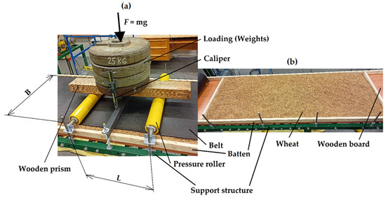
Figure 5.
(a) Measurement of deflection in the middle between rollers. (b) Even distribution of wheat.
It was advisable to address the simpler static task first, and deal with the dynamic problem of belt movement and transport of loose material later. The cover belt was pressed against the wheat by means of pressure rollers, to which weights were gradually added, i.e., the force was increased /N/, and in addition the belt was stretched by the tensile force /N/. The wheat was placed on a sufficiently thick wooden board, which conveniently served to simulate the plane of symmetry. The magnitude of the transverse load by the rollers was known and the tensile force was measured by a strain gauge.
After loading with forces, the deflection of the belt was measured at the locations of the pressure rollers and in the middle between the rollers /m/ using a digital caliper with an accuracy of 0.01 mm. A schematic diagram of the bulk compression with marked symmetry planes, from which the computational model for solving the problem was based, is shown in Figure 6.

Figure 6.
Diagram of loose material compression with marked symmetry planes.
In the basic experiment (see Figure 5), only 2 pressure rollers at a distance of L = 0.5 m were considered. More pressure rollers would not have brought about any significant refinement of the experiment or further analytical solutions. The reason for this was that the distance between the rollers was sufficiently large and therefore there was very little influence of one roller on the other. This was also consistent with the theory and practice of infinitely long beams on an elastic foundation, see e.g., [15,16,17,18,19,20,21], and the experiment further satisfies the symmetry conditions of the problem, which are addressed in the following text.
The grains were aligned to a constant height h/2 /mm/ and the grains were randomly arranged in a natural way.
2.4. Analytical Calculation of the Stiffness of an Elastic Foundation
In mechanical engineering calculations, a real situation is always simplified using a computational model that should be sufficiently accurate and reliable for the design of technical units. This is a common practice and therefore our computational model is based on the theory of beams on an elastic foundation.
An elastic foundation is very often used in engineering practice and historically verified as a suitable description of the generally very complex interaction of mechanical contact between beam and foundation. More information on the theory and practice of beams on an elastic foundation can be found, for example, in [15,16,17,18,19,20,21].
2.4.1. The Winkler Model of Elastic Foundation
The Winkler bilateral elastic foundation model is one of the first, simplest and most widely used elastic foundation models (1867), see e.g., [15,16,17,18,19,20,21]. The Winkler model is based on the assumption that the continuous reaction of the foundation is directly proportional to the deflection at the site under investigation. This basic model does not consider plastic and non-linear deformations of the foundation, which is consistent with reality, as realistic loading on the conveyor will not result in plastic damage to the belt or loose material.
The situation of mechanical interaction between the conveyor belt and the loose material (transported material) can therefore be suitably replaced by a beam (conveyor belt) on an elastic foundation (loose material). For simplicity and with negligible error, the belt was considered to be an infinitely long beam. Conveyor belts are also commonly considered endless in conveyor belt transport.
Alternatively, the problem can be solved using a more complex computational model of a plate on an elastic foundation, see e.g., [22], or the problem can be solved numerically, e.g., using FEM, see e.g., [23], but the attraction of the simplicity of the analytical solution would be lost.
Since the problem is symmetric and can be replaced by a beam, only a quarter of the compressed section of loose material can be addressed under these assumptions. In Figure 6, this part of the section is marked with a thick line and the rest of the compressed section of the loose material is replaced by symmetry planes. These are the XZ plane, i.e., the horizontal plane of symmetry (in the experiment this plane of symmetry is represented by a sufficiently rigid wooden board on which the wheat was evenly spread), and the YZ plane, i.e., the vertical plane of symmetry, which is not considered in the experiment because it would not bring about any simplification in the measurement, see Figure 6. A diagram of the computational model is shown in Figure 7.

Figure 7.
Belt of conveyor as a beam on an elastic foundation using symmetry.
Since the conveyor belt was subjected to tensile and bending stresses during operation, it was desirable to apply the second-order theory for beams on an elastic foundation. Homogeneous differential equations of a beam on a Winkler elastic foundation and their general solution for the interval , are given in Table 1 or [14].

Table 1.
General solution of an infinite beam on an elastic foundation for .
2.4.2. Boundary Conditions of the Analytical Solution
The belt (beam) is symmetrical, the plane of symmetry YZ is at the point . The beam is also loaded by a transverse point force at a distance of L/2 and an axial tensile force . The boundary conditions of vertical symmetry are
The beam must also satisfy the conditions of continuity of the equations of deflection, rotation and bending moments over the distance . A continuity of the given quantities must be valid at all points of the interval . In the distance the condition of a step change in the shearing force must also be satisfied. The mentioned boundary conditions are given in Equations (2)–(5).
An infinite beam also satisfies the boundary conditions of zero response to load at infinity, e.g., and , which is already taken into account in Table 1.
Based on the boundary conditions mentioned here, the following “simple” analytical solution of the beam can be derived, which can be conveniently used to solve the required compression of the loose material by the conveyor belt. The particular/applicable solution/integral is therefore given by the relationships in Table 2.
Table 2.
Particular solution of a beam on an elastic foundation loaded by two point forces, and a tensile force , for and Figure 7.
2.4.3. Relationships for the Calculation of Quantities Below the Measured Points
Relationships for the calculation of deflection , rotation , bending moment and shearing force under force and midway between the forces , according to Table 1 and Figure 7, are summarised in Table 3.
Table 3.
Calculation of quantities at the measuring points, i.e., under the force and midway between the forces according to Figure 7.
2.5. Probabilistic Approaches in Mechanics
Probabilistic approaches in mechanics or engineering problems are among the modern trends in science associated with the development of computer technology [24].
The natural world around us behaves in accordance with random events or simulations. For these reasons, the application of stochastic modelling (statistics and probability) is desirable and practical. Modern trends are very often based on direct or modified Monte Carlo methods, see e.g., [25,26], which was confirmed by our practical experience, see e.g., [27,28,29], and the experience of other authors, see e.g., [30,31,32].
In practical applications, see text below, Anthill software is used, which also includes a pseudo-random number generator. In Anthill software, the period of the pseudo-random number generator is 232. Anthill software uses bounded (truncated) histograms as inputs and outputs. A histogram is an approximate representation of the distribution of numerical data. The Anthill program allows evaluation and display of multi-dimensional (multi-component) random variables [27,30,33].
The SBRA (Simulation-Based Reliability Assessment) method, which is used for probabilistic assessment of phenomena and structures, is also associated with the application of Anthill software [30,33].
3. Results
Initial experimental measurements were carried out for two different thicknesses of the loose material layer, namely for h = 36 mm and h = 72 mm. All measurements were performed at constant force magnitudes of 160.1, 282.7, 405.3, 527.9 and 594.9 N (the initial measurement at h = 72 mm also used the forces of 99.5, 222.1, 344.7, and 477 N, which were further dropped).
All measurements always started at a certain tensile force in the unloaded state, i.e., , before adding weights (increasing the transverse force ), thus increasing the force which was measured by a strain gauge.
After each increment of force (e.g., from 160.1 to 282.7), the deflection under the forces and midway between the forces were measured. The relationships for these deflections from Table 3, here rewritten into Equations (6) and (7), were used with the measured deflection values to calculate the Winkler modulus of foundation for the individual measurements.
where are the non-linear relations from Table 1.
Equations (6) and (7) are non-linear equations, where the unknown is the Winkler modulus of foundation . This modulus is calculated using Equation (6) for the deflection and is denoted as ; similarly, Equation (7) is used to calculate the deflection to obtain the modulus . There are therefore two independent non-linear equations and which can be solved by the Newton–Raphson method, e.g., in the MATLAB program [34].
The Newton–Raphson method for solving non-linear equation consists of successive calculations of iterations , where is the first derivative of the function and is the initial iteration, which must be chosen close enough to the sought solution for the method to converge. The equation is solved in a similar way. For more information on the Newton–Raphson method, see e.g., [35].
An example of a solution for a layer thickness h = 72 mm is given in tabular and graphical form, see Table 4 and Figure 8. The graphical representation was created in the format .
Table 4.
Winkler moduli of foundation /Nm−3/ for individual measurements for the thickness of the wheat layer h = 72 mm according to Figure 7.

Figure 8.
Relationship /Nm−3/ for wheat layer thickness h = 72 mm.
Table 4 contains both measured and calculated values. In the first measurement, the deflections were measured only under the forces and the deflection midway between the forces was not measured. Later, however, it was considered useful to start measuring the deflection midway between the forces to provide more data for better model fitting and stochastic processing.
The solution for a wheat layer thickness of h = 36 mm is similar and is shown here only graphically, see Figure 9.

Figure 9.
Relationship /Nm−3/ for wheat layer thickness h = 36 mm.
3.1. Basic Processing of Results
From Figure 8 and Figure 9a large characteristic spread of values can be seen, which is consistent with the reality of loose materials. Due to the above-mentioned variability, it is advisable to statistically process and evaluate the results. For simplicity, and for the efficiency of the solution and experiment, the results for a given wheat layer thickness h were approximated with the following function , which adequately describes reality and thus gives the expected value (mean). To preserve the linearity of the problem (linear differential equations, see Table 1) it is advisable to use a deflection-independent function of the form , where /m−3/ and /Nm−3/ are the regression constants, and the forces and are independent variables that do not compromise the linearity of the function. It is not advisable to look for a dependency e.g., that is no longer linear.
Statistical processing was performed in MATLAB2021b [34] using the “Curve Fitting Toolbox”. The data (see Figure 8 and Figure 9) were interleaved with the aforementioned linear function (see Figure 10 and Figure 11) where the boundary edges of the planes are marked “Line A” to “Line H” for better orientation in the following figures. is the regression for h = 72 mm and is the regression for h = 36 mm.

Figure 10.
Approximated data with a linear function /Nm−3/ for wheat layer thickness h = 72 mm.

Figure 11.
Approximated data with a linear function /Nm−3/ for wheat layer thickness h = 36 mm.
Approximating the measured and calculated data with a linear function gives the following: the relationship for the Winkler modulus of foundation /Nm−3/ for a wheat layer thickness h = 72 mm has the form (8), and /Nm−3/ for a wheat layer thickness h = 36 mm has the form (9).
.
Both the measured data and the processed results, i.e., Equations (8) and (9), show that the magnitude of the pressing force and tensile force has an effect on the magnitude of the Winkler modulus of foundation, and the thickness of the loose material layer plays a role as well.
3.2. Stochastic Processing of Results
Anthill software [33] was used for stochastic processing of the results.
An error was identified /1/, see (10), between the analytical values of the Winkler moduli of foundation (see Figure 7 and Figure 8 and Table 4) and the calculated functional values, see Equations (8) and (9).
where /Nm−3/ is the analytical Winkler modulus of foundation (i.e., a , see Figure 8 and Figure 9 and Table 4) and /Nm−3/ is the function value of the Winkler modulus of foundation, see Equations (8) and (9).
The standard deviation of the error was then calculated from these error values for a wheat layer thickness of h = 72 mm and for h = 36 mm. The standard deviations were used to produce normalised histograms with normal distributions that range in intervals ⟨⟩ and ⟨⟩. Equations (8) and (9) were stochastically multiplied by the given histograms to produce the relationships
In accordance with the programming in the Anthill software environment, truncated normal histograms were used, see Figure 12 and [29], which in random simulation gave random values from the corresponding intervals ⟨⟩ and ⟨⟩.

Figure 12.
Truncated normal histograms /1/ and /1/.
A uniform distribution of forces and was assumed for the simulations, which both ranged from 0 to 1000 N, and a total of 106 pseudo-random simulations were run.
In Figure 13, 2D histograms are shown, in which it can be seen that the green lines delimit the area with the most frequent occurrence of values, i.e., these are functions and ; these lines are labelled according to Figure 10 and Figure 11. Values outside this region are the result of multiplying functions by histograms and do not contradict reality.

Figure 13.
2D histograms /Nm−3/ (top) and /Nm−3/ (bottom).
4. Discussion
Experimental measurements were carried out on laboratory test equipment of our own design, i.e., a conveyor with a cover belt and pressure rollers. As a first step, the purpose of the measurements was to determine the stiffness of the loose material of wheat (Triticum aestivum) grains free of bran (see Figure 5). The original measurements were performed for two different thicknesses of loose material, namely for h = 72 mm and h = 36 mm using the symmetry boundary conditions. In the experiment, the displacement of the rollers and the displacement midway between the rollers were measured using calipers when a force was applied, which was induced by increasing the weights, and the axial tensile force was measured by using a strain gauge. The measured values were used to calculate the stiffness at the belt–wheat interface according to Winkler.
To enable the calculation of the stiffness of the wheat, the conveyor was suitably and practically simplified to a beam on an elastic foundation. The cover belt was treated as a beam, the pressure rollers were replaced by point forces and the interaction with the wheat was a bilateral Winkler elastic foundation. A relatively “simple” linear mechanics problem was then solved analytically (see Figure 6 and Figure 7). Winkler moduli of foundation were numerically calculated using non-linear Equations (6) and (7), see also Table 3. From the calculated values, a relatively large but natural degree of variability was found, which was mainly due to the difference in the values of and when measured under the same conditions at two different locations, i.e., under the force and midway between the forces and with random arrangement of the wheat. For this reason, such a function was sought that would provide a dependence between the Winkler modulus of foundation and the forces and . It was found that one of the simplest functions, namely a linear function (plane) of the form gave great results. From the resulting functional relationships for the mean values and it could be seen that the transverse force had a greater effect on stiffness than the longitudinal force , but the thickness of the loose material also had a contribution to the stiffness (in the functional relationships, this is reflected by a constant—i.e., the last member of relationships and —which represents the stiffness at zero force loading and ).
The experiment and its evaluation showed that the Winkler modulus of elasticity was not constant and that it was influenced by several factors mentioned above, but the values were in the same range as those commonly reported in the literature for loose materials or elastic foundations, see e.g., [14,15].
Due to the relatively large variability, a stochastic approach was used, where the functions and were multiplied by normalised histograms with normal distributions, which were generated using the standard deviation calculated from the errors between the analytical and approximated solutions, see Equations (11) and (12). In this way, a larger range of values could be obtained and the natural randomness could be preserved, which better described the results obtained from the experiment and the real situation.
In the future, other aspects could be added to the measurements, such as non-uniform material distribution, or another, more complicated model of the elastic foundation could be considered for the evaluation, e.g., the Hetényi model, which was marginally used and presented e.g., in [21], see also [36,37]. The differential equation for the Winkler model is , see Table 1, and the differential equation for the Hetényi model is , where /Nm−3/ and /Nm/ are the moduli of Hetényi foundation.
The beam model can be changed to a shell model or a plane strain model and other stochastic approaches or dynamic solutions can also be used, see e.g., [22,23,24,25,26,27,28,29,30,31,32,38,39,40,41,42,43,44,45,46]. FEM could also be used, but this would lose the elegantly simple and uncomplicated analytical solution and would also make the use of stochastic methods more complex and difficult. FEM can also be used to solve dynamic tasks, e.g., the start-up, steady-state, run-out and hard stop of the conveyor; modal analysis; vibration diagnostics, etc. [47].
The presented and used methodology and experimental equipment can also be used for other types of loose materials, e.g., sand, sawdust, gravel, etc., in the branch of engineering design of belt conveyors and material transport.
5. Conclusions
A simple, original test device for static compression of loose materials by a sandwich belt conveyor was developed and applied.
A series of measurements were carried out on the transport of wheat grains. The basic properties of wheat as a loose material were evaluated.
The analytical model of the Winkler elastic foundation was simply and appropriately used as a simple and reliable alternative to the more demanding numerical solution using FEM.
From the experimental results, i.e., the deflections under the rollers and the deflections midway between the rollers, non-linear analytical relations for the Winkler elastic moduli of foundation and were determined using the iterative Newton–Raphson method. Subsequently, these values were statistically and stochastically processed. Regression dependencies on the thickness of the wheat layer h = 36 and h = 72 mm and the transverse load forces and the axial forces in the belt have emerged.
In the stochastic evaluation, the given regression dependencies were stochastically multiplied by normalised histograms with normal distribution, and the Monte Carlo method (probabilistic approach) was used to obtain relationships that better described the naturally occurring randomness of the real situation.
The results are considered primary and new. The new methodology was demonstrated and explained and other possible approaches and applications of the solution are also mentioned.
In this paper, only wheat uniformly distributed between the belts of a sandwich belt conveyor was practically solved. Future work is planned to research the uneven (random) distribution of wheat and other loose materials between the belts, which is a typical non-uniformity in belt conveying.
The obtained results, or more generally the whole presented methodology, can be used for practical tasks of engineering research and development of belt conveyors and their design. The solution of the problem as an application of elastic foundation and stochastic approaches is a novelty in this field of belt conveyor design.
Author Contributions
Conceptualisation, K.F.; Methodology, L.H.; Resources, L.H.; Software, D.Č. and M.N.; Writing—original draft, D.Č.; Writing—review and editing, K.F. and D.Č. All authors have read and agreed to the published version of the manuscript.
Funding
This article is supported by project CZ.01.1.02/0.0/0.0/20_321/0024559 “Development of an innovative, standardised, without engine room rope lift for four-storey houses”, Czech projects SP2022/26, SP2022/2 and international projects CZ.02.1.01/0.0/0.0/17_049/0008441 “Innovative Therapeutic Methods of Musculoskeletal System in Accident Surgery” and CZ.02.1.01/0.0/0.0/17_049/0008407 “Innovative and additive manufacturing technology—new technological solutions for 3D printing of metals and composite materials” within the Operational Programme Research, Development and Education financed by the European Union and from the state budget of the Czech Republic.
Data Availability Statement
Data sharing is not applicable to this article.
Acknowledgments
Ministry of Industry and Trade of the Czech Republic from the Specific Research Project CZ.01.1.02/0.0/0.0/20_321/0024559 (MP342132), Czech projects SP2022/26, SP2022/2 and international projects CZ.02.1.01/0.0/0.0/17_049/0008441 and CZ.02.1.01/0.0/0.0/17_049/0008407.
Conflicts of Interest
The authors declare no conflict of interest.
Nomenclature
| /m/ | Integral constants for the solution of a differential equation, see Table 1 | |
| /mm/ | Largest grain length | |
| /m−3/ | Regression constant | |
| B | /m/ | Belt width |
| /m−3/ | Regression constant | |
| /Nm−3/ | Regression constant | |
| /rad/ | Slope (first derivative of deflection) | |
| /m−1/ | Second derivative of deflection | |
| /m−3/ | Fourth derivative of deflection | |
| E | /Pa/ | Young’s Modulus of a Belt |
| /1/ | Error between analytical and approximated values of Winkler moduli of elastic foundation | |
| e | /1/ | Euler’s number |
| /N/ | Loading force | |
| Function of and | ||
| First derivative of function | ||
| FEM | Finite Element Method | |
| g | /ms−2/ | Gravity acceleration |
| Function of and | ||
| h | /mm/ | Loose material layer thickness |
| /1/ | Truncated normal histogram created from | |
| /1/ | Truncated normal histogram created from | |
| i | /1/ | Index |
| /m4/ | Principal second moment of cross-sectional area of a belt | |
| /Nm−3/ | Winkler modulus of elastic foundation | |
| /Nm−3/ | Winkler modulus of foundation calculated from deflections | |
| /Nm−3/ | Hetényi modulus of foundation | |
| /Nm/ | Hetényi modulus of foundation | |
| /Nm−3/ | Analytical Winkler modulus of foundation (i.e., and ) | |
| /Nm−3/ | Winkler modulus of foundation calculated from deflections | |
| /Nm−3/ | Winkler modulus of foundation in initial iteration | |
| /Nm−3/ | Winkler modulus of foundation in nth iteration | |
| /Nm−3/ | Winkler modulus of foundation in nth + 1 iteration | |
| /Nm−3/ | Approximation function of Winkler modulus of foundation | |
| /Nm−3/ | Approximation function of Winkler modulus of foundation for h = 36 mm | |
| /Nm−3/ | Stochastic function of Winkler modulus of foundation for h = 36 mm | |
| /Nm−3/ | Stochastic function displayed by Anthill software | |
| /Nm−3/ | Approximation function of Winkler modulus of foundation for h = 72 mm | |
| /Nm−3/ | Stochastic function of Winkler modulus of foundation for h = 72 mm | |
| /Nm−3/ | Stochastic function displayed by Anthill software | |
| L | /m/ | Span between pressure rollers |
| /Nm/ | Bending moment in the belt | |
| m | /kg/ | Weight of loading |
| /N/ | Tensile force in the belt | |
| /1/ | Index | |
| Steps | /1/ | Number of Monte Carlo random simulations |
| /N/ | Shearing force in the belt | |
| t | /m/ | Thickness of the belt |
| /m/ | Deflection of belt | |
| /m/ | Deflection of belt midway between the forces | |
| /m/ | Deflection of belt under the force | |
| x | Axis X of coordinate system | |
| /m/ | General distance from the origin of coordinate system | |
| y | Axis Y of coordinate system | |
| z | Axis Z of coordinate system | |
| ψd | Loose grain angle | |
| /m−1/ | Parameter of solution of differential equation | |
| /m−1/ | Parameter of solution of differential equation | |
| /m−1/ | Parameter of solution of differential equation | |
| /kgm−3/ | Loose weight | |
| /1/ | Standard deviation of error for a wheat layer thickness h = 36 mm | |
| /1/ | Standard deviation of error for a wheat layer thickness h = 72 mm |
References
- ČSN 260002; Material Handling. Nomenclature. Publishing Office for Standards and Measurement: Prague, Czech Republic, 1983; p. 19.
- ISO 7149; Equipment for Smooth Transport of Loads. Safety Regulations. Special Provisions. Czech Standards Institute: Prague, Czech Republic, 1993; p. 32.
- Michalik, P.; Dobransky, J.; Hrabovský, L.; Petruš, M. Assessment of the Manufacturing Possibility of Thin-Walled Robotic Portals for Conveyor Workplaces. Adv. Sci. Technol. Res. J. 2018, 12, 338–345. [Google Scholar] [CrossRef]
- Hrabovský, L.; Fries, J. Transport Performance of a Steeply Situated Belt Conveyor. Energies 2021, 14, 7984. [Google Scholar] [CrossRef]
- Hrabovský, L. Loose Material Filling in the Loading trough Profile of the Belt Conveyor. In Proceedings of the IOP Conference Series: Materials Science and Engineering, Prague, Czech Republic, 9–11 September 2021; Volume 1190. [Google Scholar] [CrossRef]
- Hrabovsky, L.; Molnar, V.; Fedorko, G.; Tkac, J.; Frydrysek, K. Experimental Determination of Force Acting on a Sandwich Conveyor’s Pressure Roller in Transport of Bulk Materials for the Needs of Failure Analysis. Measurement 2022, 202, 111832. [Google Scholar] [CrossRef]
- Hrabovský, L.; Blata, J.; Hrabec, L.; Fries, J. The Detection of Forces Acting on Conveyor Rollers of a Laboratory Device Simulating the Vertical Section of a Sandwich Belt Conveyor. Measurement 2023, 207, 112376. [Google Scholar] [CrossRef]
- Fedorko, G.; Molnar, V.; Vasil, M.; Salai, R. Proposal of Digital Twin for Testing and Measuring of Transport Belts for Pipe Conveyors within the Concept Industry 4.0. Measurement 2021, 174, 108978. [Google Scholar] [CrossRef]
- Zegzulka, J. Mechanics of Loose Materials; VŠB-Technical University Ostrava: Ostrava, Czech Republic, 2004; p. 186. ISBN 80-248-0699-1. [Google Scholar]
- Gelnar, D.; Zegzulka, J. Discrete Element Method in the Design of Transport Systems: Verification and Validation of 3D Models; Springer International Publishing: Cham, Switzerland, 2019; ISBN 978-3-030-05712-1. [Google Scholar]
- RSCC. Available online: https://www.hbm.cz/produkty/kategorie/rscc/ (accessed on 12 November 2022).
- State Standard for the Specific Weight of Cereals with a Volume of 20 l. Available online: https://www.cmi.cz/statni%20etalon%20objemove%20hmotnosti%20obilovin (accessed on 14 November 2022).
- ČSN EN ISO 7971-1; Cereals—Determination of the Specific Weight, Also Known as the ‘Hectolitre Weight’—Part 1: Reference Method. Office for Technical Standards, Metrology and Testing: Prague, Czech Republic, 2010; p. 20.
- ČSN EN ISO 7971-2; Cereals—Determination of the Specific Weight, Also Known as the ‘Hectolitre Weight’—Part 2: Traceability Method for Measuring Instruments to Verify the Instrument According to the International Standard. Office for Technical Standards, Metrology and Testing: Prague, Czech Republic, 2019; p. 36.
- Frydrýšek, K.; Jančo, R.; Nikodým, M. Beams and Frames on Elastic Foundation 3; VŠB—Ostrava Technical University: Ostrava, Czech Republic, 2010; p. 463. ISBN 80-248-1244-4. [Google Scholar]
- Qissab, M.A. Flexural Behaviour of Laterally Loaded Tapered Piles in Cohesive Soils. OJCE 2015, 05, 29–38. [Google Scholar] [CrossRef]
- Avramidis, I.E.; Morfidis, K. Bending of Beams on Three-Parameter Elastic Foundation. Int. J. Solids Struct. 2006, 43, 357–375. [Google Scholar] [CrossRef]
- Sato, M.; Kanie, S.; Mikami, T. Mathematical Analogy of a Beam on Elastic Supports as a Beam on Elastic Foundation. Appl. Math. Model. 2008, 32, 688–699. [Google Scholar] [CrossRef]
- Winkler, E. Die Lehre von Der Elastizitat und Festigkeit (The Theory of Elasticity and Stiffness); H. Dominicus: Prague, Czech Republic, 1867. [Google Scholar]
- Hetenyi, M. Beams on Elastic Foundations; University of Michigan Press: Ann Arbor, MI, USA, 1946. [Google Scholar]
- Hrabovský, L.; Frydrýšek, K.; Čepica, D. Winkler and Hetenyi Elastic Foundation Applied in Belt Conveyors for Wheat Transport. In Proceedings of the 27/28th International Conference Engineering Mechanics 2022, Milovy, Czech Republic, 9–12 May 2022; pp. 149–152. [Google Scholar]
- Li, R.; Zhong, Y.; Li, M. Analytic Bending Solutions of Free Rectangular Thin Plates Resting on Elastic Foundations by a New Symplectic Superposition Method. R. Soc. A Math. Phys. Eng. Sci. 2013, 469, 20120681. [Google Scholar] [CrossRef]
- Silva, A.; Silveira, R.; Gonçalves, P. Numerical Methods for Analysis of Plates on Tensionless Elastic Foundations. Int. J. Solids Struct. 2001, 38, 2083–2100. [Google Scholar] [CrossRef]
- Benaroya, H.; Han, S.M.; Nagurka, M. Probability Models in Engineering and Science; CRC Press: Boca Raton, FL, USA, 2005; ISBN 978-0-8247-2315-6. [Google Scholar]
- Kalos, M.H.; Whitlock, P.A. Monte Carlo Methods, 2nd ed.; Wiley-VCH: Weinheim, Germany, 2008; ISBN 978-3-527-40760-6. [Google Scholar]
- Kroese, D.P.; Rubinstein, R.Y. Monte Carlo Methods. WIREs Comput. Stat. 2012, 4, 48–58. [Google Scholar] [CrossRef]
- Frydrýšek, K. Monte Carlo Probabilistic Approach Applied for Solving Problems in Mining Engineering. In Intelligent Systems for Computer Modelling; Stýskala, V., Kolosov, D., Snášel, V., Karakeyev, T., Abraham, A., Eds.; Springer International Publishing: Cham, Switzerland, 2016; pp. 75–85. [Google Scholar] [CrossRef]
- Frydrýšek, K.; Čada, R. Probabilistic Reliability Assessment of Femoral Screws Intended for Treatment of “Collum Femoris” Fractures. In Proceedings of the Biomechanics 2014: International Conference of the Polish Society of Biomechanics: Abstracts, Łódź, Poland, 1–3 September 2014; Lodz University of Technology: Łódź, Poland, 2014; pp. 61–62, ISBN 978-83-7283-628-1. [Google Scholar]
- Frydrýšek, K.; Šír, M.; Pleva, L.; Szeliga, J.; Stránský, J.; Čepica, D.; Kratochvíl, J.; Koutecký, J.; Madeja, R.; Dědková, K.P.; et al. Stochastic Strength Analyses of Screws for Femoral Neck Fractures. Appl. Sci. 2022, 12, 1015. [Google Scholar] [CrossRef]
- Marek, P. Probabilistic Assessment of Structures Using Monte Carlo Simulation: Background, Exercises and Software; Institute of Theoretical and Applied Mechanics Academy of Sciences of the Czech Republic: Prague, Czech Republic, 2003; ISBN 978-80-86246-19-2. [Google Scholar]
- Křivý, V.; Marek, P. Zur probabilistischen Bemessung von Stahlrahmen. Stahlbau 2007, 76, 12–20. [Google Scholar] [CrossRef]
- Lokaj, A.; Vavrusova, K.; Rykalova, E. Application of Laboratory Test Results of Dowel Joints in Cement-Splinter Boards VELOX into the Fully Probabilistic Methods (SBRA Method). Appl. Mech. Mater. 2012, 137, 95–99. [Google Scholar] [CrossRef]
- Milan Gustar; Pavel Marek. Anthill (Version 10 Pro). Available online: http://www.noise.cz/sbra/software.html (accessed on 11 November 2022).
- MATLAB. Computer software, 9.11.0.1769968 (R2021b); The MathWorks Inc.: Natick, MA, USA, 2021.
- Quarteroni, A.; Riccardo, S.; Fausto, S. Numerical Mathematics, 2nd ed.; Springer: Berlin/Heidelberg, Germany, 2007; ISBN 978-3-540-34658-6. [Google Scholar] [CrossRef]
- Younesian, D.; Hosseinkhani, A.; Askari, H.; Esmailzadeh, E. Elastic and viscoelastic foundations: A review on linear and nonlinear vibration modelling and applications. Nonlinear Dyn. 2019, 97, 853–895. [Google Scholar] [CrossRef]
- Dillard, D.A.; Mukherjee, B.; Karnal, P.; Batra, R.C.; Frechette, J. A review of Winkler’s foundation and its profound influence on adhesion and soft matter applications. Soft Matter 2018, 14, 3669–3683. [Google Scholar] [CrossRef]
- Čajka, R.; Vašková, J.; Vašek, J. Numerical Analyses of Subsoil-structure Interaction in Original Non-commercial Software based on FEM. In Proceedings of the IOP Conference Series: Earth and Environmental Science, Ho Chi Minh City, Vietnam, 17–19 April 2018; Volume 143, p. 012003. [Google Scholar] [CrossRef]
- Murčinková, Z.; Šmeringaiová, A.; Halapi, M. Damping properties of composites with short and long fibres by impact testing. AIP Conf. Proc. 2019, 2077, 020042. [Google Scholar]
- Murčinková, Z.; Postawa, P.; Winczek, J. Parameters Influence on the Dynamic Properties of Polymer-Matrix Composites Reinforced by Fibres, Particles, and Hybrids. Polymers 2022, 14, 3060. [Google Scholar] [CrossRef]
- Vavrušová, K.; Mikolášek, D.; Lokaj, A.; Klajmonová, K.; Sucharda, O.; Parenica, P. Determination of Carrying Capacity of Steel-Timber Joints with Steel Rods Glued-In Parallel to Grain. Wood Res. 2016, 61, 733–740. [Google Scholar]
- Famfulík, J.; Míková, J.; Lánská, M.; Richtář, M. A Stochastic Model of the Logistics Actions Required to Ensure the Availability of Spare Parts During Maintenance of Railway Vehicles. Proc. Inst. Mech. Eng. Part F J. Rail Rapid Transit. 2014, 228, 85–92. [Google Scholar] [CrossRef]
- Tvrdá, K. Probability and Sensitivity Analysis of Plate. Appl. Mech. Mater. 2014, 617, 193–196. [Google Scholar] [CrossRef]
- Malerová, L.; Pokorný, J.; Kristlová, E.; Wojnarova, J. Using of mobile flood protection on the territory of the Moldova as possible protection of the community. IOP Conf. Ser. Earth Environ. Sci. 2017, 92, 12039. [Google Scholar] [CrossRef]
- Haniszewski, T.; Margielewicz, J.; Gąska, D.; Opasiak, T. New Crane Bumper Design with an Energy Absorption Device System. Transp. Probl. 2022, 17, 5–16. [Google Scholar] [CrossRef]
- Lesňák, M.; Maršálek, P.; Horyl, P.; Pištora, J. Load-Bearing Capacity Modelling and Testing of Single-Stranded Wire Rope. Acta Montan. Slovaca 2020, 25, 192–200. [Google Scholar] [CrossRef]
- Ungureanu, M.; Medan, N.; Ungureanu, N.S.; Pop, N.; Nadolny, K. Tribological Aspects Concerning the Study of Overhead Crane Brakes. Materials 2022, 15, 6549. [Google Scholar] [CrossRef]


Disclaimer/Publisher’s Note: The statements, opinions and data contained in all publications are solely those of the individual author(s) and contributor(s) and not of MDPI and/or the editor(s). MDPI and/or the editor(s) disclaim responsibility for any injury to people or property resulting from any ideas, methods, instructions or products referred to in the content. |
© 2023 by the authors. Licensee MDPI, Basel, Switzerland. This article is an open access article distributed under the terms and conditions of the Creative Commons Attribution (CC BY) license (https://creativecommons.org/licenses/by/4.0/).