1. Introduction
In recent years, many advanced countries have seen unprecedentedly low birth rates combined with a significant increase in life expectancy, leading to a shrinking working-age population and an increasing proportion of elderly people. In response to this looming crisis, businesses have proposed various measures, such as extending the retirement age, as a countermeasure to the rapidly shrinking working-age population [
1]. This is also the case in Korea, where the proportion of elderly people aged 65 or above is expected to increase from the 2018 level of 14.3% to 20.0% by 2025. The country is now on the verge of entering into a phase of a super-aged society. The proportion of elderly workers engaged in economic activities, in particular, has been steadily on the rise since 2010; this is a typical structural feature found in an aging society [
2].
The industrial sector of Korea has generally been driven by manufacturing-based industries, which fall into category C under the International Standard Industrial Classification (ISIC), and these manufacturing businesses are generally based on labor-intensive production. In recent years, various attempts have been made in manufacturing industries to shift away from the current labor-intensive practices by embracing robots and autonomous systems to automate production lines. However, the application of such robots and autonomous systems has been limited to systemized production processes only. At the same time, industrial accidents have been increasing, especially in fields where most production processes are still based on human labor, due to poor work environments and excessive workloads. One promising response to meeting the needs of industrial fields, where it is difficult to apply robots and autonomous systems, has been to propose wearable robots capable of helping enhance the muscle strength of workers. Wearable robots are classified according to their structure into several types, including skeleton types, which are characterized by rigid outer covers, and flexible wearable suits, which include textile and artificial muscle types [
3,
4,
5,
6]. Hardiman was the first skeleton-type wearable robot, developed by the GE Research Laboratory in 1960 with support from the US Navy. Since then, other skeleton-type wearable robots have been developed in various forms in defense and industrial fields [
7].
These skeleton-wearable robots can be further divided according to their actuating mechanisms into active and passive types. The active types use various devices, such as motors, reducers, controllers, batteries, and sensors, to enhance the muscle strength of workers, while the passive types employ elastic bodies for that purpose. Here, it is worth noting that active skeleton-type wearable robots include heavy parts, such as actuators and power sources, and thus the overall weight of the system is often excessively high. This may cause users inconvenience when wearing the suit.
In an attempt to overcome these limitations, passive-type wearable devices which do not require separate actuators or battery systems have been studied and developed. Alternatively, modular skeleton-type muscle-assistive wearable devices, which are designed to selectively enhance the muscle strength of local regions of interest, have also been actively investigated in studies focused on weight reduction. Various types of passive shoulder muscle-assistive wearable devices have been developed. Representatively, The EksoVest (EksoBionics, San Raphael, CA, USA), the Airframe (Levitate Technologies, San Diego, CA, USA), the ShoulderX (SuitX, Emeryville, CA, USA), and the PAEXO shoulder (Ottobock, Duderstadt, Germany) have been developed to reduce muscle activity in the shoulder area during the tasks above over shoulder height [
8,
9,
10,
11,
12,
13]. These muscle-assistive wearable devices are being applied to various types of industrial fields. The Ekso Vest developed by EksoBionics has been deployed in a pilot project by Ford. In Korea as well, Vex and Cex, developed by the Hyundai Motor Company, are scheduled to be used in pilot projects by Kia [
14,
15]. These wearable devices are expected to contribute to improved field worker productivity while reducing the occurrence of musculoskeletal injuries arising from the aging of the working-age population.
Against this backdrop, the present study aimed to analyze various types of work, especially work performed in unstructured postures by heavy industry workers, who are frequently exposed to high workloads and poor work environments. Based on the analysis results, an attempt was made to develop a shoulder muscle-assistive wearable device capable of supporting those who work using their shoulder muscles. Various types of unstructured posture work are performed in heavy industries, including activities such as the welding and grinding of ship components and plant structures, which are typically conducted in narrow spaces with limited postures, and cause many workers to suffer muscle fatigue. When welding and grinding the lower body of vessels or internal structural parts of offshore plants, field workers often have to perform overhead-type work, which requires them to bear the load or weight of tools and parts for an extended period of time.
The goal of this paper is the development of a shoulder muscle-assistive wearable device that can be applicable in the areas of heavy industry. As the first step of development, different working scenarios were investigated and experimented with, and the corresponding motion data and required torque values were estimated using motion capture devices. The obtained motion data and required torque values were reflected in the design of the wearable device.
2. Methods
To develop shoulder muscle assistive wearable device, we proceeded with the working environment investigation, motion experimentation, analysis of given tasks, data acquisition for the range of motion and required joint torques, design of mechanical structure of wearable systems according to the obtained data, and applying lightweight system using composite materials. The vertical direction is only considered as support force direction of wearable device, and the entire design process is based on the grinding tasks in shipyards in this paper.
2.1. Investigation of Working Environment and Tasks
The industrial sector of Korea has thus far been driven by manufacturing-based, labor-intensive industries, such as construction, metal processing, automobiles, and heavy industries. The aging of the country’s working-age population has resulted in an increase in the average age of workers. However, the labor-intensive nature of this work may lead to potential musculoskeletal injuries of workers, and cause workers to avoid these industries. In particular, in the shipbuilding industry, robots or autonomous systems often cannot be employed due to limited space and complex installation requirements, and thus human workers are required to perform various types of work in unstructured postures instead.
In the present study, various types of unstructured posture work conducted in heavy industries, especially large-scale shipbuilding, were identified and analyzed, and based on these results, methods of implementing and applying a shoulder muscle-assistive wearable device for these applications were explored.
To develop a shoulder muscle-assistive wearable system, the authors of the present study made a visit to a heavy industry company’s site to identify and analyze types of work requiring shoulder muscle assistance. Based on the results, the applicability of the system was evaluated. Specifically, during a visit to a site operated by Samsung Heavy Industries, working motions in unstructured postures performed in the shipbuilding process of N,000-ton TEU container ships were studied. In general, large-scale ships are built by assembling different modular blocks produced at external workshops into block units. In the process, each block is joined together through welding, and the resultant welding beads are then treated by grinding. These welding and grinding operations are usually performed on ground docks, and due to spatial restrictions, human workers are deployed to perform the job.
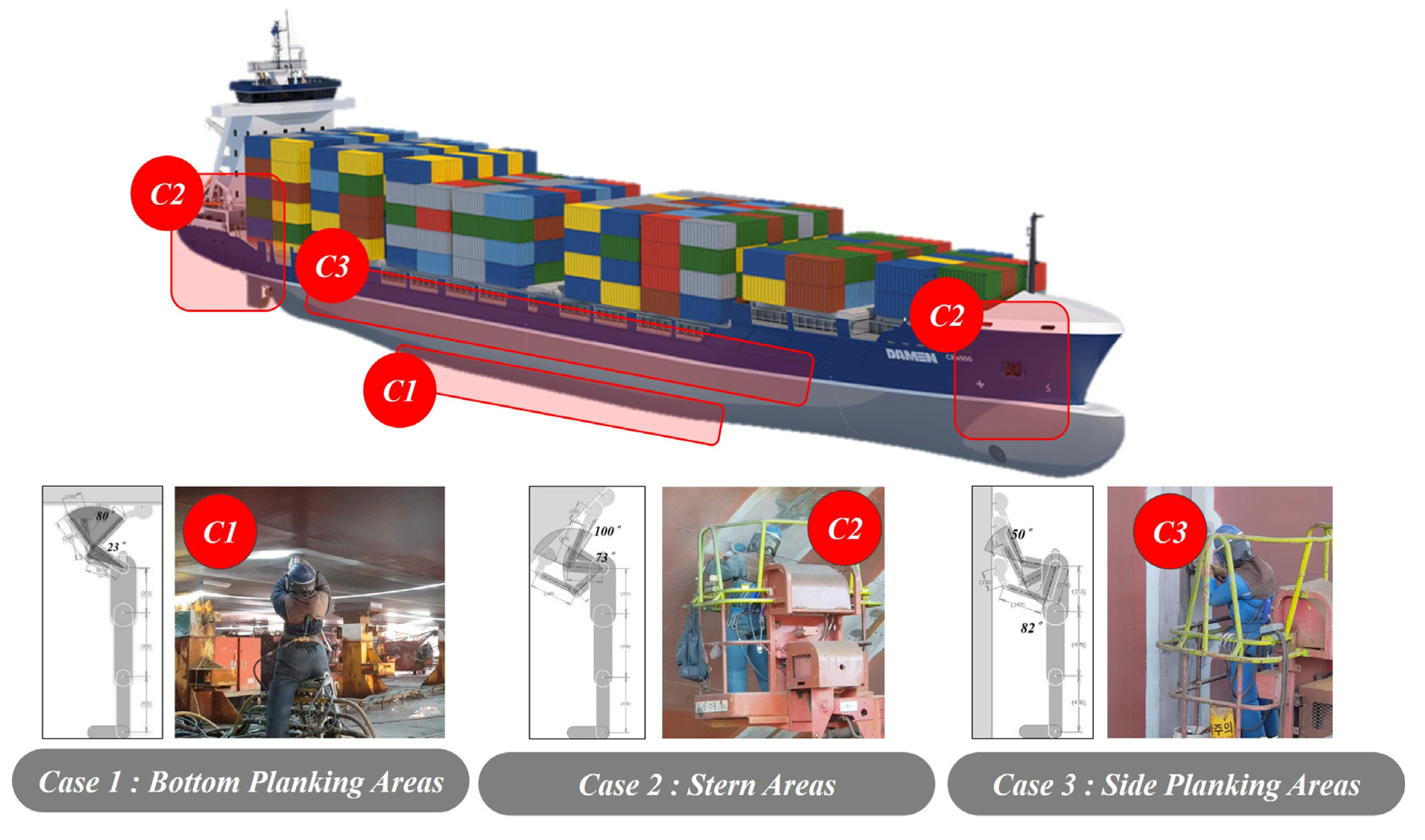
Among the welding and grinding operations performed in the assembly of modular ship blocks, the following three areas are known to require shoulder muscle assistance: bottom planking areas (Case 1), stern areas (Case 2), and side planking areas (Case 3). The bottom planking areas are where workers are required to work on the bottom planks of a ship positioned over their heads, and thus these workers suffer the most severe muscle fatigue.
Figure 1 presents the working motions performed in shipbuilding by section.
2.2. Motion Analysis of Grinding Tasks
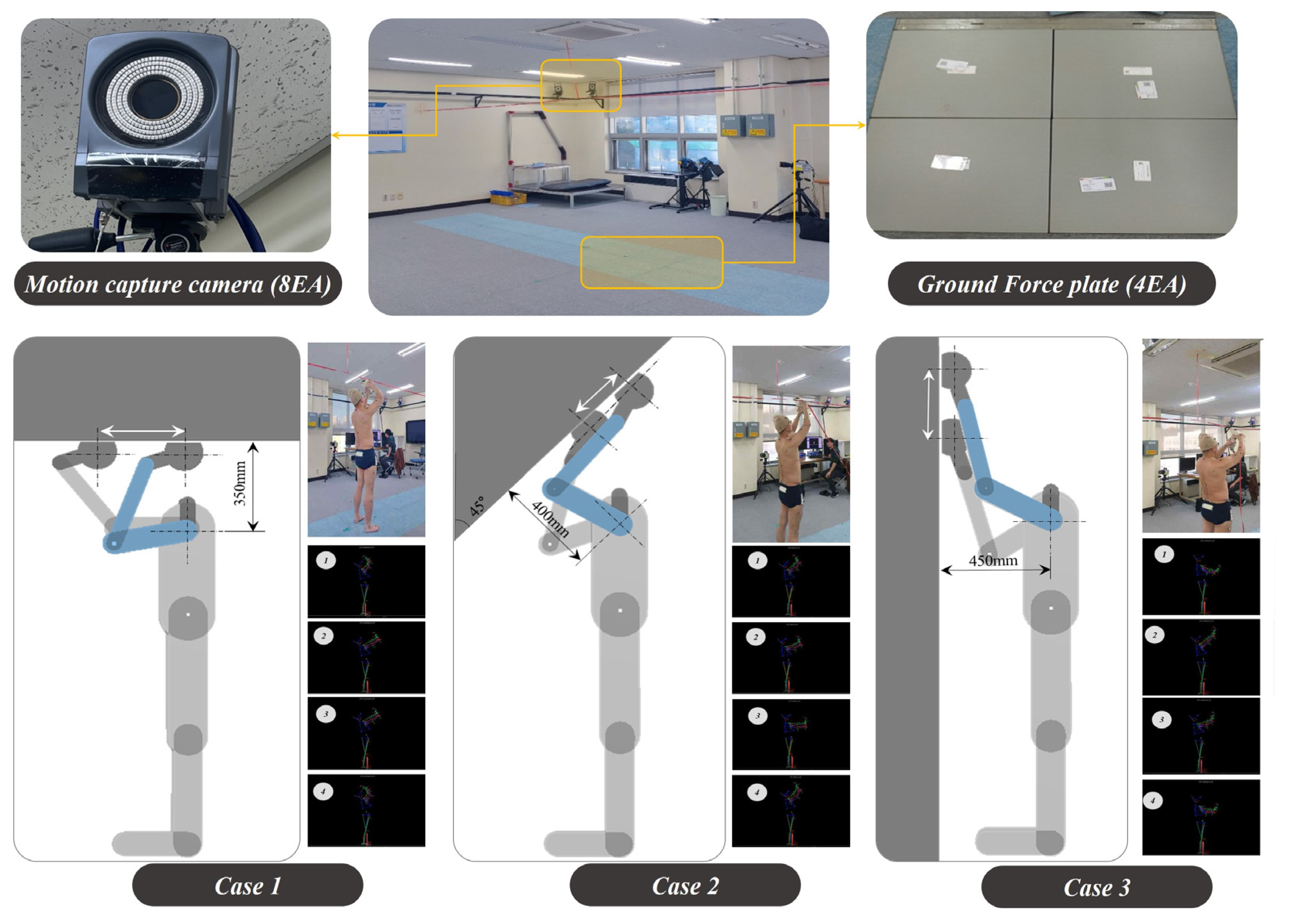
Through field survey and analysis, three working motions performed in unconstructed postures during shipbuilding were identified, and these motions were then analyzed using a motion capture device. The motion capture device was composed of eight motion capture cameras installed on the upper body, combined with four ground force plates on the lower body. In this study, the motion analysis was performed with a Vicon Motion Capture System (Vicon, Yarnton, Oxford, UK). Motion capture data were transferred to Windows-based data acquisition software (Vicon, Nexus ver. 1.8.5). Vicon system includes passive markers, sync box, and 8 high-resolution cameras (Vicon, MXT Series T40) with infrared illumination, located on holder and positioned around the testing area (approximate volume dimensions, Height × Width × Length = 2 m × 6 m × 6 m). Measurements were performed at frequency of 100 Hz. Ground reaction forces were measured synchronously using ground-embedded force plates (AMTI, Watertown, MA, USA) during the task motion.
The motion capture process was performed in accordance with the requirements described in
Figure 2 to accurately simulate the three working motions identified through field research. During the motion capture sessions, the subject was asked to carry a tool weighing 2.4 kg in an attempt to simulate the external force exerted on workers in the field.
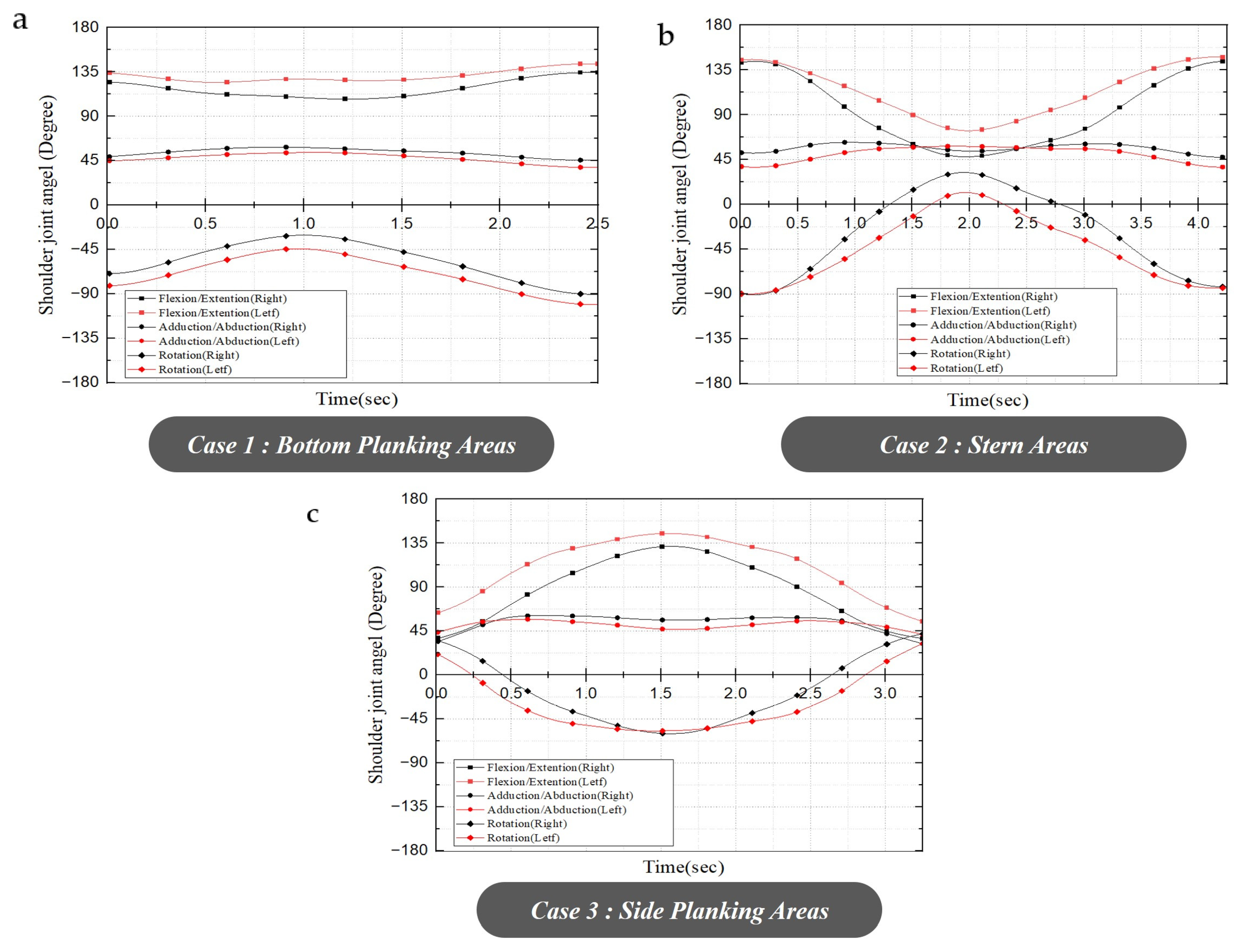
In these motion capture, the range of motion (ROM) of the shoulder joints that occurred while performing the three identified working motions was determined, as shown in
Figure 3.
Figure 3a–c present the ROM of the shoulder joint in the bottom planking areas, stern areas, and side planking area, respectively. The ROMs of the shoulder joint in the flexion and extension directions where the highest load is applied during working were 95.74° and 95.77° for Case 2 and Case 3, respectively, and were larger than that for Case 1, at 26.98°.
The shoulder joint torque results were calculated, including the weight of the upper arm and the weight of the tool carried. For the torque results of the shoulder joint considering the weight of the upper arm, the result calculated through Vicon Nexus program was used. The plug-in gait full-body model was used for kinematics and kinetics models while performing motion capture [
16,
17,
18]. The torque of the shoulder joint generated by the tool was calculated as an approximate value through the weight of the moment arm and tool based on the angle result of the joint derived through motion capture.
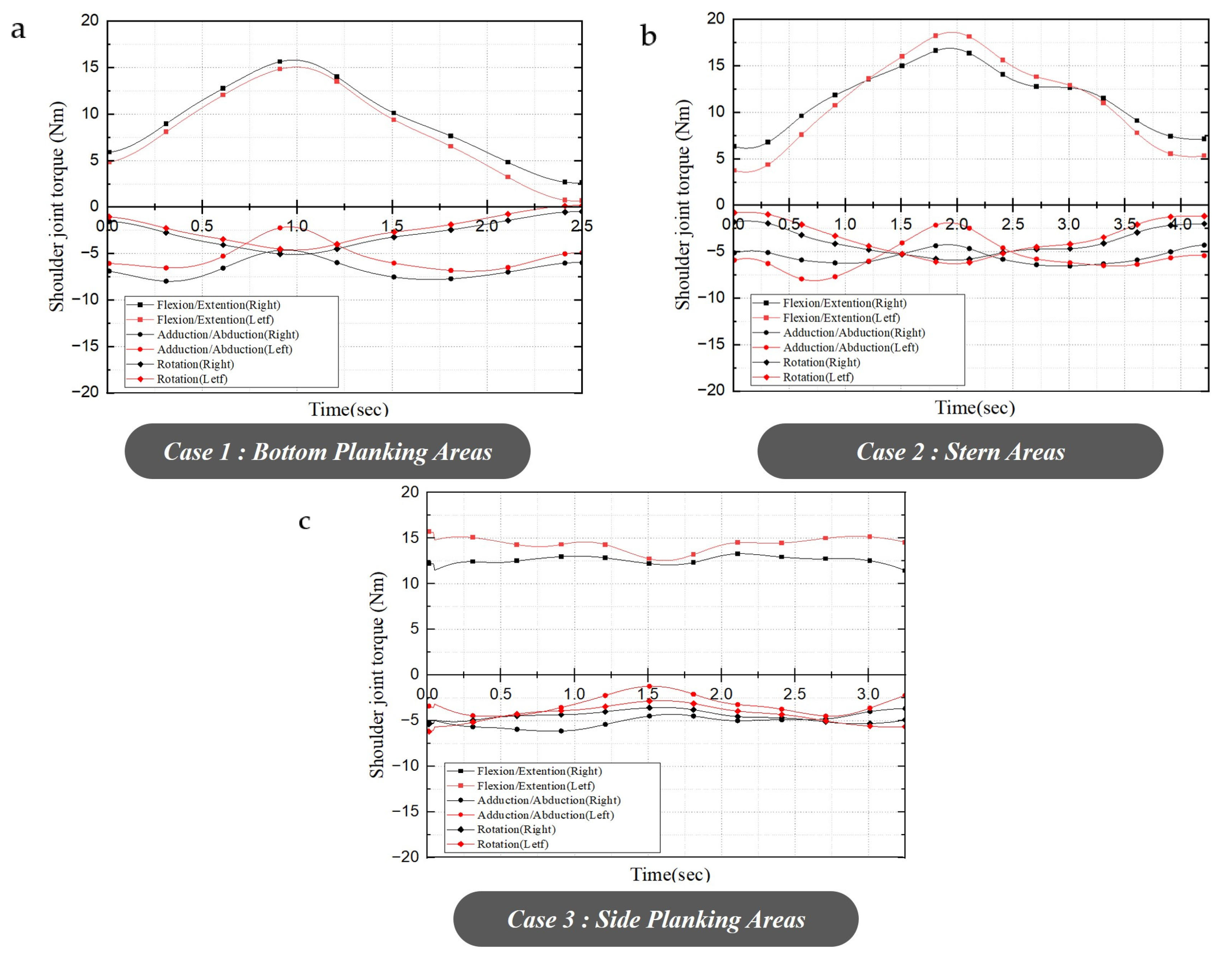
Figure 4 shows the results of torque at the shoulder joint due to the weight of the upper arm and the mass of the tool during motion capture. The results showed that the maximum torque generated in the left shoulder joint in Case 1 was 15.82 Nm, and the variation in the torque during each motion was 14.40 Nm, as shown in
Figure 4a. In Case 2, as shown in
Figure 4b, the maximum torque was 18.61 Nm, and the variation in torque during each motion was 15.05 Nm. Finally, in Case 3, as shown in
Figure 4c, the maximum torque was 15.72 Nm, and variation in the torque during each motion was 3.17 Nm. As such, the physical load for each posture was analyzed using motion capture, and based on the results, the maximum torque generated in the shoulder joint was determined to be 15.05 Nm. The shoulder joint angle and torque results of various working motions at motion capture are listed in
Table 1.
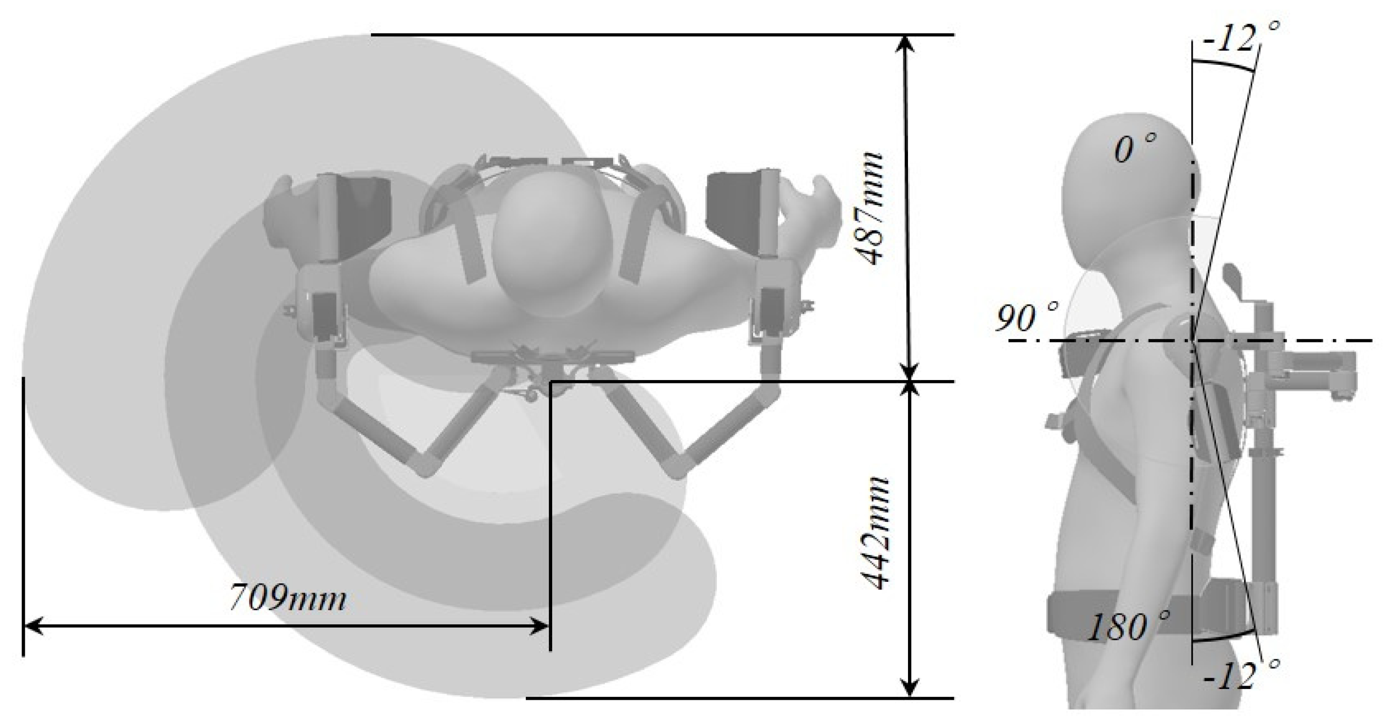
The structure of the shoulder muscle-assistive wearable device needed to permit the ROM without limiting the degrees of freedom of the user. To this end, the ROM of the muscle-assistive wearable device was determined based on the ROM of each joint of the wearer, obtained through motion capture, along with the configuration of its lightweight structure, as shown in
Figure 5. The lightweight structure was designed to cover both the ROM of the wearer’s joints, as determined through motion capture, and the general ROM of the human body.
Figure 5 presents detailed specifications of the resulting structure based on the necessary ROM.
The structure of shoulder muscle-assistive wearable device had three multi-links on each arm for free planar movement (in transverse plane). The multi-link has a low-friction bushing applied to enable free rotation. In addition, it is configured to support the load in the direction of gravity (vertical direction) through the gravity compensation module located at the shoulder joint of structure of shoulder muscle-assistive wearable device. In the case of the degree of freedom configured through the multi-joint and gravity compensation module applied to the shoulder muscle-assistive wearable device, it can follow the movement caused by flexion and extension of the shoulder. The internal rotation of the arm was configured to freely rotate through the gap between the user’s arm and the arm holder of shoulder muscle-assistive wearable device.
2.3. Design of Gravity Compensation Mechanism
Based on the ROM and physical load data obtained in the application environment analysis, a shoulder muscle-assistive wearable device was designed. The developed muscle-assistive wearable device was composed of gravity compensation modules, which generate a supporting force to enhance the shoulder muscle strength of workers, a lightweight structure, which bears the overall load of the system, and a harness that allows the device to be worn by the user. The assistive module was designed to operate based on the elastic force of its torsion spring. The system structure was made of composite material to reduce the overall weight of the system.
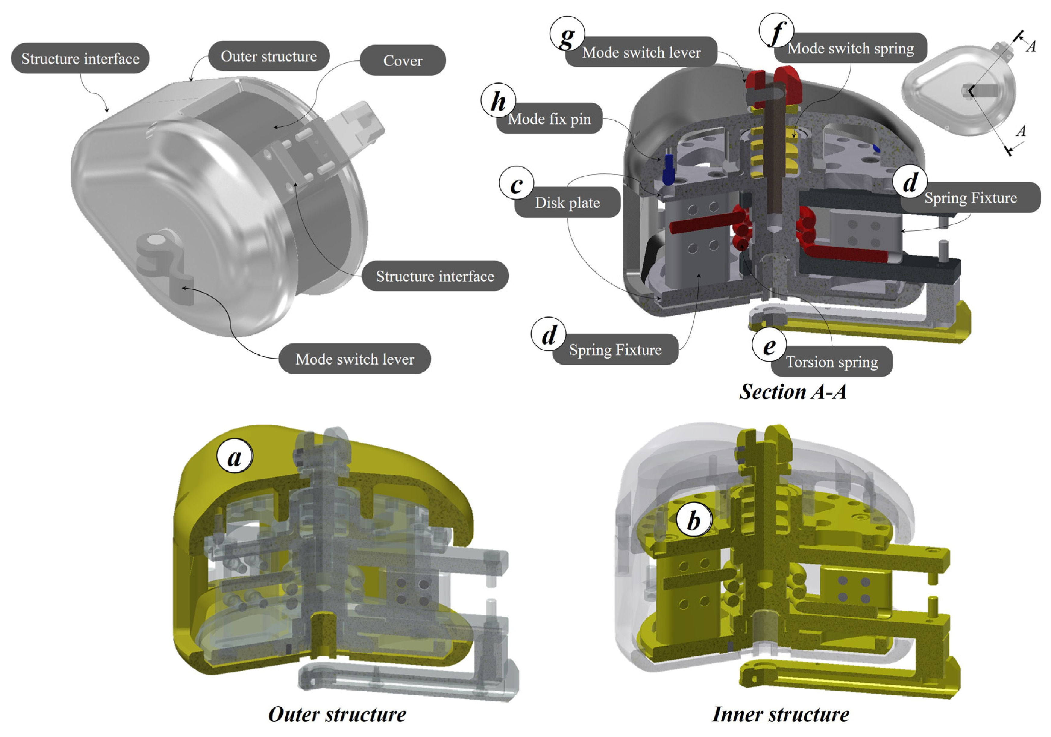
Figure 6 presents a detailed illustration of the designed gravity compensation module. The gravity compensation module was configured to allow the generated supporting force to be transmitted to the wearer through a disk connected to the internal torsion spring. In contrast, this gravity compensation module was designed to use its multi-layered disk connected to the torsion spring on demand. When the wearer needs supporting force, he or she can simply operate the mode lever installed on the outer structure to allow the disk connected to the torsion spring to be connected with the system structure. The outer structure in
Figure 6 is responsible for the external structure of the muscle strength support module and transits the assistive force to the user through the structure interface located in the front (
Figure 6a).
Figure 6b shows disk plate (
Figure 6c), torsion spring (
Figure 6e), spring fixture (
Figure 6d), mode switch spring (
Figure 6f), and mode switch lever (
Figure 6g) that composed the inner structure. The inner structure generates support force through a torsion spring located inside. The user can obtain the support force by combining the outer structure and inner structure through the mode change lever at any desired posture. Additionally, when the support force is not needed, the outer structure and inner structure are configured to rotate freely through the bush at the center of rotation.
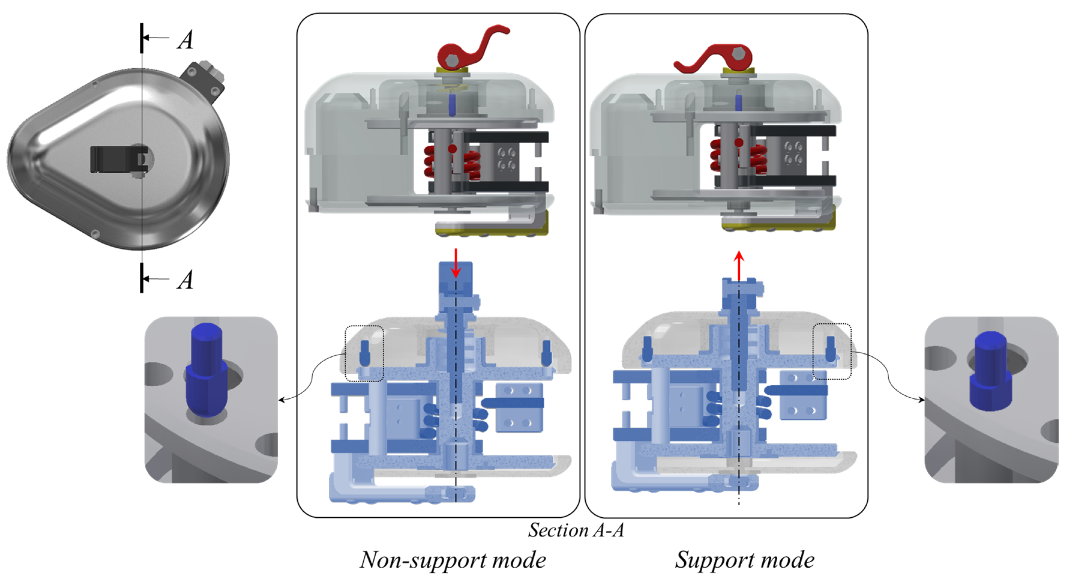
Figure 7 depicts the operation of the support mode and non-support mode of the gravity compensation module. When the user operates the mode switch lever at the desired location, the position of the inner structure moves. At this time, the mode fix pin attached to the outer structure is combined with the disk plate of the inner structure. Thus, the inner–outer combined module can deliver the support force generated from the torsion spring to the user.
The designed gravity compensation module has different operating ranges for the following two modes. In a free motion mode, when supporting force is not needed, the maximum rotation was set to 195°. In the supporting force mode, the rotation range was set to 60° from the angle designated by the user. The torsion spring used in the gravity compensation module was made of SUS304WPA. Its diameter was 4 mm, and its internal diameter was 20 mm. The number of windings was 4.4, and the final torsion angle was set to 60°. The maximum load of the torsion spring was set to 4.47 Nm at its ends. This gravity compensation module with the embedded torsion spring was designed to be attached to both shoulder joints and transmit up to 8.94 Nm of supporting force to the shoulder joints of the wearer of the muscle-assistive wearable device.
2.4. Lightweight System
The structural body of the muscle-assistive device accounts for most of its weight and thus needs to be lightweight. If muscle-assistive wearable devices are heavy, they may provide less effective muscle assistance and increase the degree of fatigue experienced by the wearer due to the dead-weight load. In the present study, the structural body of the system was composed of carbon-fiber-reinforced plastic, one of the most widely used lightweight materials. Carbon-fiber reinforced composites provide excellent specific stiffness and strength and thus are widely used in applications where weight reduction is required, such as aerospace and defense [
19,
20].
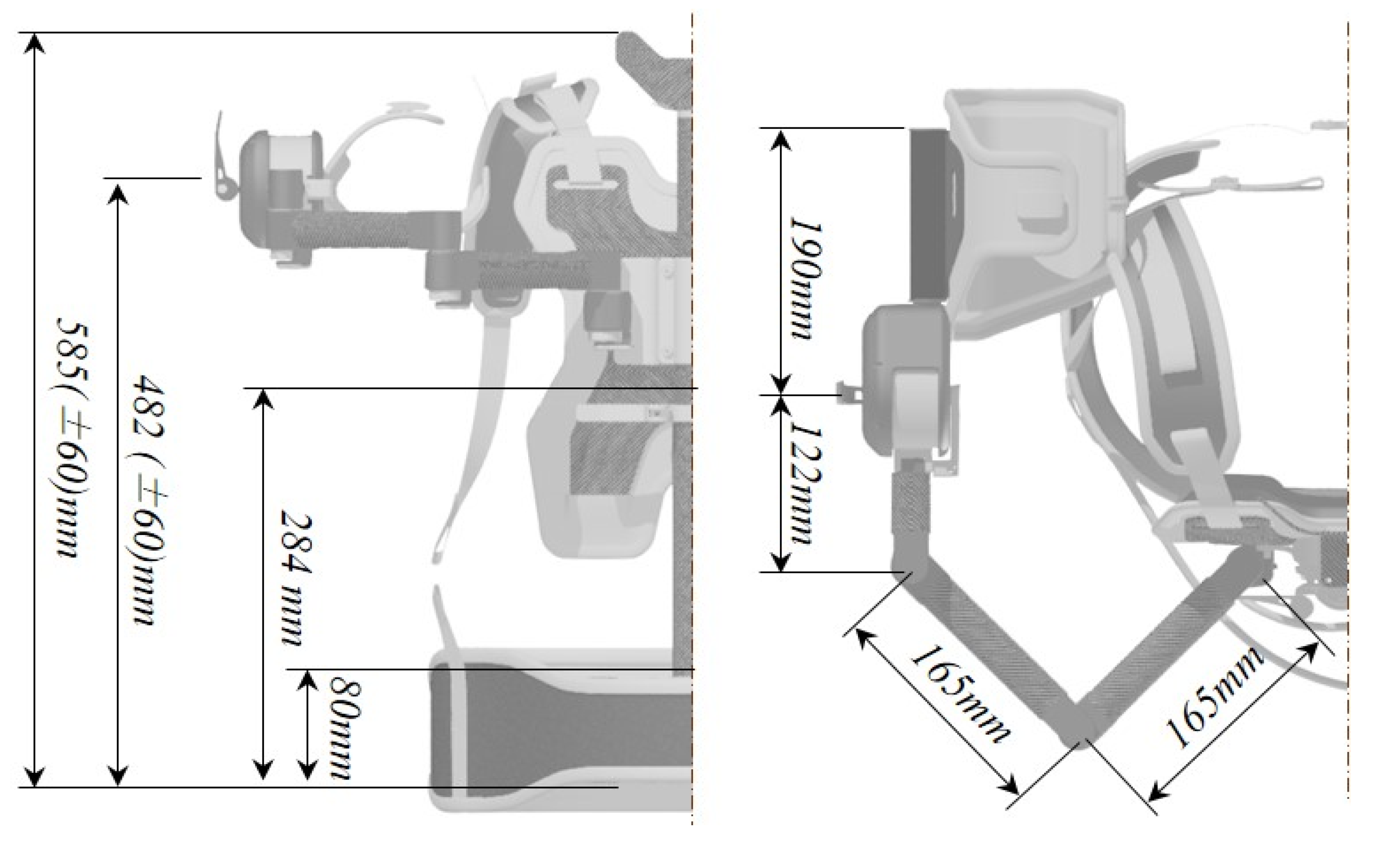
This lightweight structure was developed to fit Korean male users in their 30 s with an average height of 174 cm, considering their average body dimensions. In an attempt to ensure flexibility with respect to varying heights, the dimensions of the lightweight structure were designed to be adjusted by ±60 mm from the design dimensions. The structural parts of the system made of carbon-fiber-reinforced plastic included the parts which bear the load of the system, such as the main structure and substructure, and the link structure, which implements the degree of freedom of the system. Structural parts made of carbon-fiber reinforced composite are advantageous in that their strength and stiffness can be adjusted as desired by the designer. To be more specific, the required strength and stiffness can be achieved with a relatively smaller amount of material simply by aligning the applied uni-direction fibers in the principal load direction.
Figure 8 presents a detailed illustration of the lightweight structure.
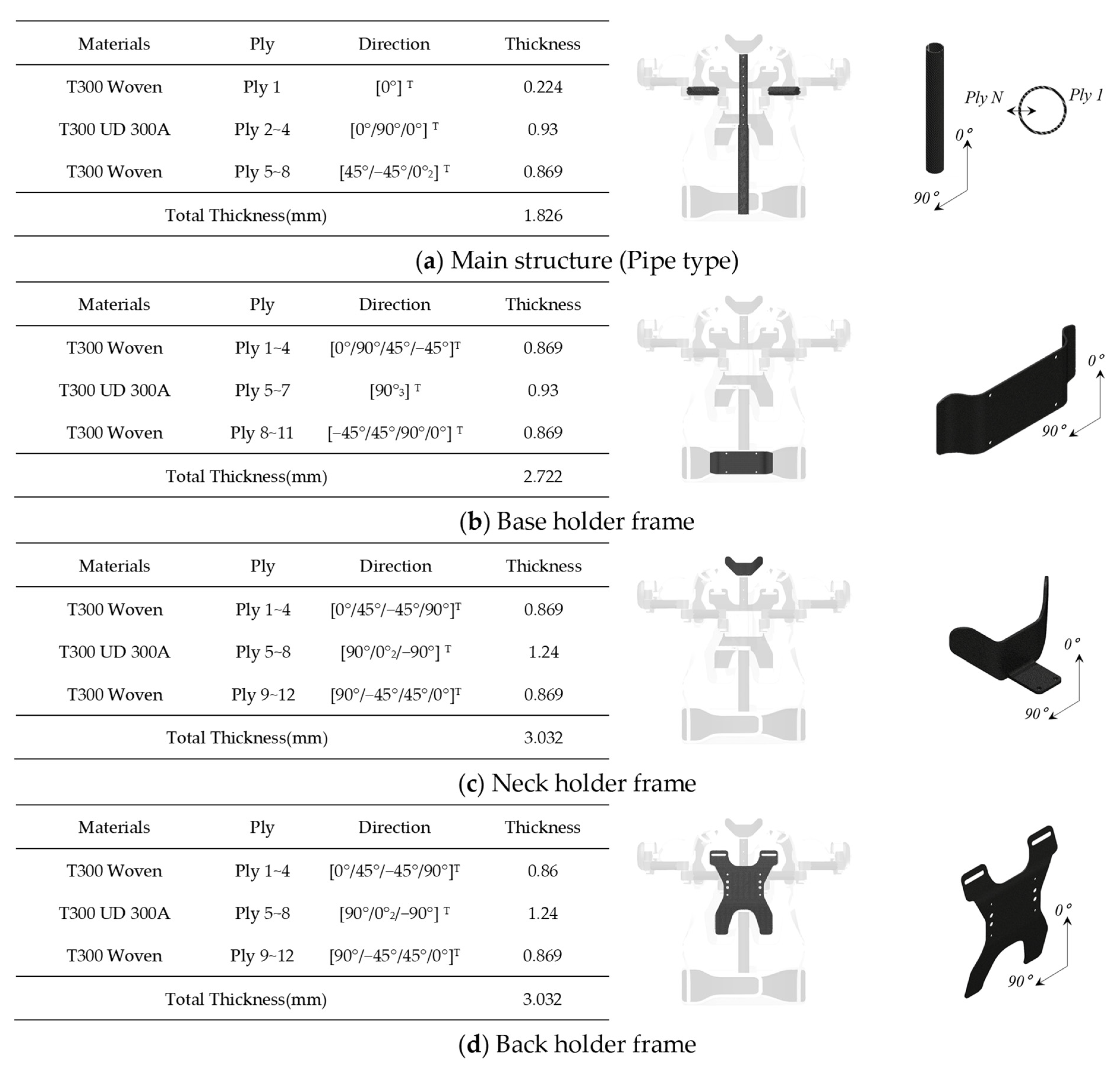
In the present study, a T300 uni-direction carbon fiber prepreg was stacked in the direction of the applied load, and subsequently, the T300 woven carbon fiber prepreg was further stacked on both the inner face and outer face of the system to reduce shear stress and prevent in-plane failure.
Figure 9 shows the morphology and stacking sequence of the lightweight structure.
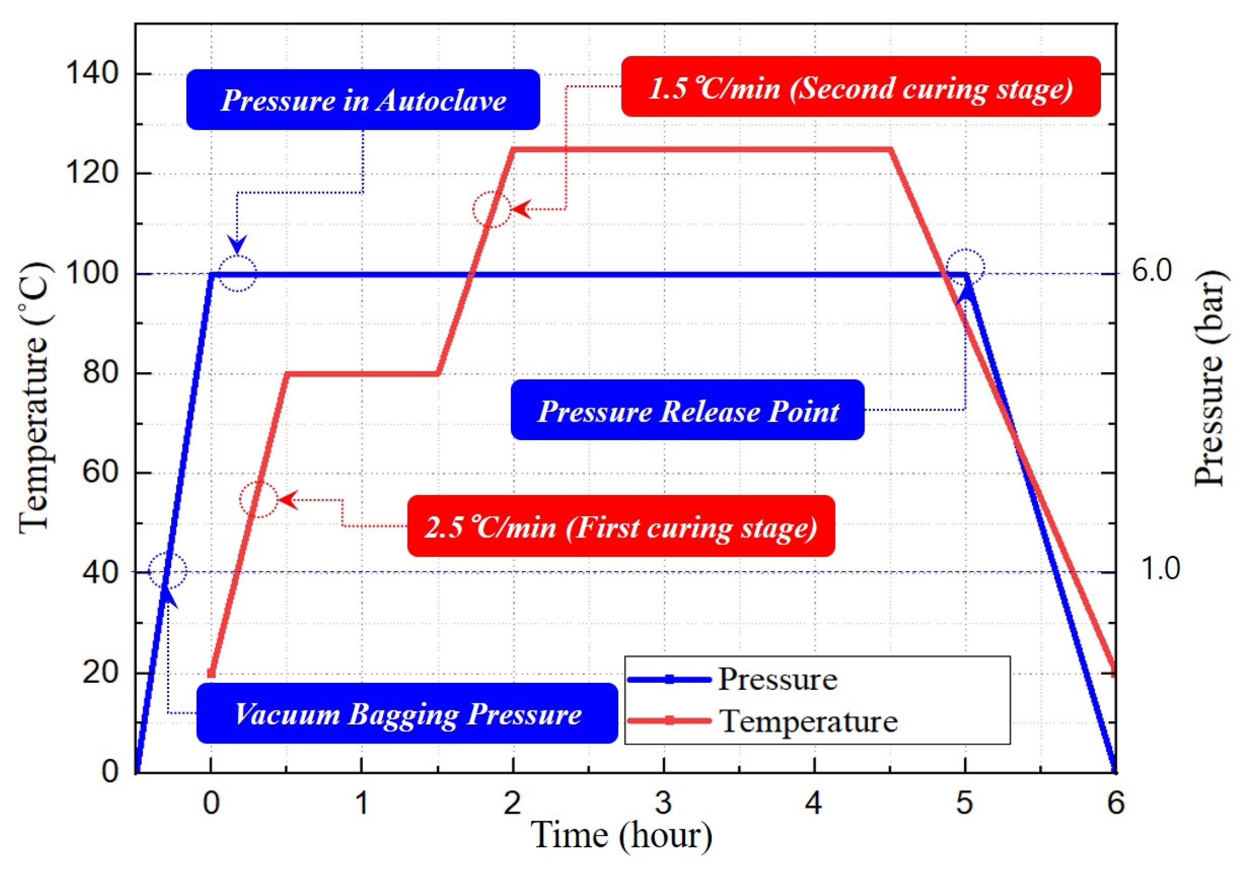
The lightweight structure was fabricated using autoclave molding, a method employed to produce high-quality and performance molded products. In the autoclave process, laminates are stacked according to the shape of the target product and then put in a vacuum bag, in which the stacked laminates are subjected to a constant temperature (125 °C) and pressure (6 bar). This molding process ensures that stacked laminates are tightly joined together, providing excellent inter-planar bonding. Meanwhile, the linking structure links the metal parts comprising the system to the parts made of composite material. Methods for joining composite parts to those made of other types of material are classified into mechanical and chemical techniques. As one of the most widely used mechanical joining methods, rivet fastening is currently widely used in the aviation industry. Adhesive-based joining methods are among the most widely used chemical joining techniques and are widely applied to rocker motor cases. In the present study, aluminum inserts were fabricated to join the structure made of the composite material to the metal parts of the system. The aluminum inserts were then integrated with the cured composite structure through chemical bonding. The chemical bonding process was conducted using FM73 adhesive film.
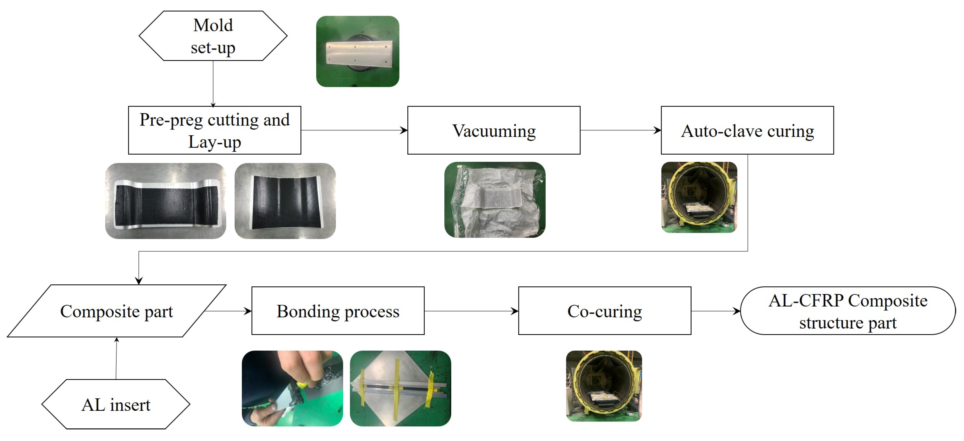
Figure 10 illustrates the autoclave curing cycle used to fabricate the composite structure. The details of the fabrication process of the composite structure are shown in
Figure 11.
3. Results
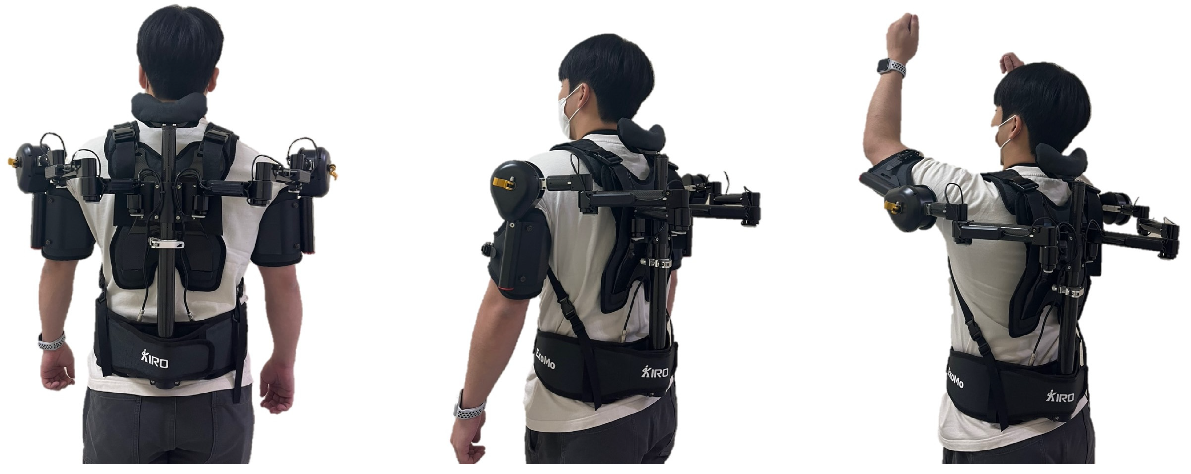
Subsequently, a harness that allowed the obtained lightweight structure to be comfortably worn by users was prepared. Fillers with a thickness of 15–30 mm were attached to a part of the harness where the device would come in contact with body parts, to reduce the fatigue experienced by the wearer. Buckles were added to the chest and abdomen areas of the wearer to secure the device tightly to the body. The harness was designed to be adjustable to fit the body size of the wearer. As a result, the gravity compensation modules, lightweight structure, and harness were all prepared and assembled into a shoulder muscle-assistive wearable device system, as shown in
Figure 12. This wearable device system weighed 4.8 kg.
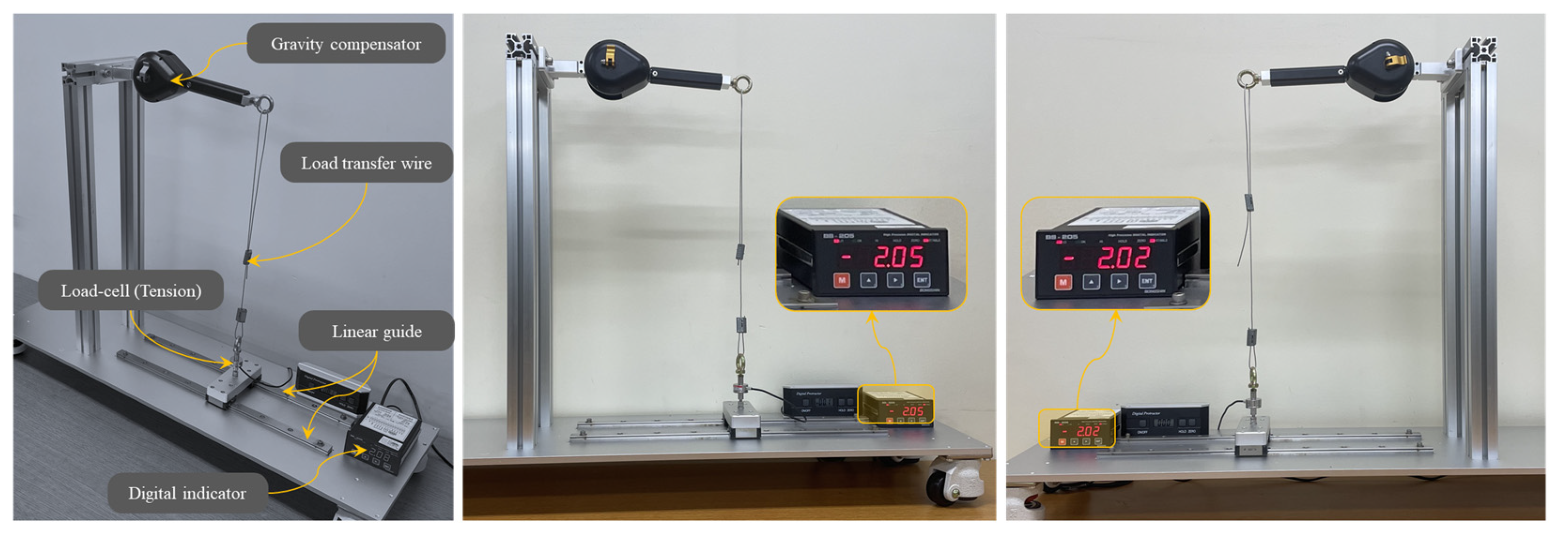
The generated torque test of the gravity compensation module was performed using test instruments, as shown in
Figure 13. The test instrument was designed, which was a composite of a linear guide, load cell, digital indicator, and load transfer wire. The load cell (Bongsin, CDFS-10, OSAN, Republic of Korea) and digital indicator (Bongsin, BS-205, Republic of Korea) were applied to the test instruments. The load cell has a maximum capacity of 10 kg and a resolution of 0.002 kg. Test equipment with a digital display can output load results in increments of 0.001 kg, according to the display panel.
Table 2 shows the results of the generated torque test of the gravity compensation module. The generated torque test of the gravity compensation module was performed five times for each left and right shoulder module. It was confirmed that each gravity compensation module was capable of generating up to 4.47 Nm of supporting force.
4. Discussions
Since the gravity compensation module provided the support force in the vertical direction, the presented wearable device can assist in shoulder abduction as well as flexion. Although it is designed based on the motion data from the grinding tasks in the shipyard, the developed shoulder muscle-assistive wearable device can be used for any upper arm work in the industrial area with a reduced payload for the upper arm and tool amount of 30%. The developed shoulder muscle-assistive wearable device provides a support force of 4.47 Nm at each shoulder joint and has a weight of 4.8 kg. A representative wearable device, the Ekso Vest, has a maximum torque of 5.4 Nm and a weight of 4.3 kg. It was confirmed that this device exhibits similar performance to the Ekso Vest. The shoulder muscle-assistive wearable device can be more optimized, so that there is still room for a more lightweight system. Since the gravity compensation system is designed as a modular type, it can be easily modified according to workplace requirements. Since the presented device is a passive type of wearable device, there are some limitations. For example, the presented wearable device is not for muscle strength but for muscle endurance. Thus, its application is limited in some workplaces that need muscle strength. Additionally, it is not functional for weak people in terms of strength, such as children or the elderly. Of course, the system weights of the active type of wearable device are heavier than the passive type, due to actuators and batteries. Nowadays, actuators and batteries are getting lightened, and the active type of wearable devices with similar system weights as the presented passive type of wearable device is considered as future work. Additionally, digitalization, or the digital twinning of the design process, and the personalization of wearable devices are considered future works at this moment.
5. Conclusions
In the present study, a shoulder muscle-assistive wearable device capable of assisting a wearer at work using shoulder muscles in unstructured postures was developed. Various types of working motions in unstructured postures that are performed by field workers in shipbuilding were identified and analyzed, and based on the results, the design requirements were determined. Using a field survey and analysis, three working motions in unconstructed postures were identified, and these motions were then simulated using motion capture. As a result, the range of motion (ROM) of the shoulder joints while performing the three identified working motions was determined, along with the required torque for each motion. A shoulder muscle-assistive wearable device was designed based on these data. The device was built using passive muscle-assistive modules in elastic bodies. For user convenience, these modules were designed to shift between the free motion mode and the supporting force mode, as desired. The structural body of the shoulder muscle-assistive modules was made of carbon fiber-reinforced composite (T300 UD/T300 Woven) to ensure they were lightweight. The developed shoulder muscle-assistive wearable device weighed 4.8 kg, and it was confirmed that each muscle-assistive module was capable of generating up to 4.5 Nm of supporting force. This wearable device is expected to provide effective muscle assistance to field workers who are required to work in unstructured postures for an extended period of time, thereby contributing to reducing musculoskeletal injuries while improving productivity.
