Article

Posture and Dynamics Analysis of Hydraulic Support with Joint Clearance under Impact Load

1
School of Mechanical and Electronic Engineering, Shandong University of Science and Technology, Qingdao 266590, China
2
School of Information Science and Engineering, Shandong Normal University, Jinan 250358, China
3
School of Energy and Mining Engineering, Shandong University of Science and Technology, Qingdao 266590, China
*
Author to whom correspondence should be addressed.
Machines 2023, 11(2), 159; https://doi.org/10.3390/machines11020159
Submission received: 1 January 2023 / Revised: 18 January 2023 / Accepted: 20 January 2023 / Published: 23 January 2023
(This article belongs to the Section Robotics, Mechatronics and Intelligent Machines)

Abstract

:
A hydraulic support is one of the key pieces of equipment in a fully mechanized coal-mining face. The shaft is seriously worn due to repeated support shifting in coal-mining operations, and the hydraulic support bears a large amount of impact load in the support process, leading to a threat to its dynamic stability. In order to study the impact load on the posture and dynamics of a hydraulic support, and considering the joint clearance of the hydraulic-support hinge point, based on the dynamics software Adams, the equivalent variable-stiffness damping system is used to replace the column, and the impact analysis model of the hydraulic support with joint clearance is established. The roof pressure is vertically applied to the load balance area of the top beam by static load, and the impact load is vertically applied to the top beam downward. Based on the above model, considering the different distributions of joint clearance, research about the influence of joint clearance on the posture and dynamic characteristics of the hydraulic support is carried out. The results show that when there is joint clearance on both sides of the hydraulic support, when the top beam bears the impact load, the X-axis PMR (position movement ratio) at different positions of the top beam is more than 80%, and the forward-tilt posture is obvious. When the hydraulic support has only unilateral clearance, the front end of the top beam bears the impact load, and the front end of the top beam moves laterally, while the rear end of the top beam mainly moves longitudinally. When the end of the top beam bears the impact load, the vertical PMR of the top beam is less than 1%. When the impact load acts on the side with joint clearance, the top beam has a certain degree of lateral offset, and the offset directions on both sides of the top beam are inconsistent. At this time, the top beam presents a torsional-bearing posture. When the front end of the top beam is loaded, the mechanical curve of each hinge point is higher than the rear-end load. For the hinge point on the side without clearance, the maximum load-fluctuation coefficient reaches 1.04, while for the hinge point on the side with clearance, the minimum load is 0 kN, which will mean some hinge points cannot to play a supporting role. The analysis results will be helpful to research hydraulic supports considering joint clearance.

1. Introduction

Coal is one of the main energy sources in the world. With the development of society, people’s demand for coal is increasing year by year. How to safely and efficiently exploit coal resources has become an urgent problem to be solved. In the process of coal mining, the overlying coal seam is usually supported by a hydraulic support, which provides an effective space for activities and a safe working environment for the coal-mining face. Therefore, it is not only necessary to improve the bearing capacity of the hydraulic support, but also to master the bearing characteristics of the hydraulic support. The effective support of the hydraulic support will ensure normal coal mining [1,2,3].
The earth’s environment is diverse, and the underground coal-mining environment is also very complex. There are many influence factors on the support performance of a hydraulic support, among which the impact load caused by the moving of coal-mining face is the most obvious and intense. At the same time, due to the repeated lifting and lowering of a hydraulic support in the working process, the hydraulic-support shaft is worn to varying degrees, which leads to the occurrence of clearance at the hinge joint. The clearance at different positions has different effects on the bearing performance of the hydraulic support. In recent years, with the popularization of comprehensive mechanized coal mining, more and more accidents of hydraulic support shaft fracture failure occur [4,5,6,7]. Therefore, a lot of research on the dynamic characteristics of hydraulic support has been carried out by many experts and scholars.
In terms of ideal support dynamics, Liang et al. [8] established the equivalent mechanical model of a hydraulic support, which did not consider the overflow condition, and analyzed the mechanical change law of each hinge point when the impact load acted on different positions of the top beam. Ren et al. [9] built an experimental model of a hydraulic support. Based on experimental and numerical simulation methods, he considered impact loads of different amplitudes, and analyzed the energy distribution characteristics of the hydraulic support. Szurgacz et al. [10,11] recorded the column state in real time and studied the response characteristics of the column under load impact. Then, based on a roadway-section-shape test method, the influence of roadway section shape on a hydraulic support was studied, and the section geometry under actual conditions was analyzed. The results show that the deformation of the roadway section may lead to the uneven distribution of hydraulic-support load. Guan et al. [12] proposed a new quadrilateral structure, built a dynamic model of a hydraulic support combined with the new structure, and analyzed the dynamic-response characteristics of the hydraulic mechanism of the hydraulic support. The results showed that the new structure strengthened the hydraulic mechanism and significantly improved the safety performance of the hydraulic support. In order to study the influence of the floor on a hydraulic support, based on a special hydraulic device, Witek et al. [13] simulated the floor with different bearing characteristics and used the finite element method to reproduce the test results. The test showed that different base plates had different effects on the load distribution of the hydraulic support. When the lower surface of the hydraulic support was fully supported, the front load of the base was reduced by about 45%.
In considering joint space, in order to study the influence of joint clearance on a robot system, Erkaya et al. [14] carried out kinematics and dynamics analysis on the robot with joint clearance. The results showed that the clearance had an important influence on the motion sensitivity of the robot. In order to study the dynamic-response characteristics of a parallel mechanism with clearance, Chen et al. [15] took the 2RPS-SPR mechanism as the research object, established the dynamic model of the parallel mechanism, analyzed the ideal situation with and without clearance, and also considered the influence of different viscosity and clearance values on the mechanism. The results showed that the lubrication of clearance could effectively improve the dynamic characteristics of parallel mechanisms. Based on the modified Flores contact-force model and Coulomb friction model, Hou et al. [16] established a dynamic analysis model of the 3RSR parallel mechanism with joint clearance and solved the 3RSR dynamic model using the Kutta method. The influence of clearance of the motion pair on the dynamic characteristics of the mechanism was studied, and the simulation results were compared with the calculation results. The results showed that the long-term wear of the hinge joint increases the fluctuation of the contact force, thus reducing the kinematic stability of the mechanism. In order to study the dynamic characteristics of the slider-crank mechanism with joint clearance, Zhao et al. [17] established a dynamic simulation model of the slider-crank mechanism, considering influence factors such as the clearance of the motion pair, the driving speed, and the load, and carried out multivariable simulation experiments and analyzed the mechanism of the joint clearance and the dynamic response law of the mechanism. Matekar, S.B. [18] established a crank-slider simulation model with adjustable clearance through ADAMS, analyzed whether there was joint clearance in the crank-slider mechanism and the influence of clearance size on slider displacement, and verified the simulation results of the crank-slider clearance model through an experimental device. In order to optimize vibration caused by the clearance of planar linkage, Bai et al. [19] considered the contact impact conditions and established a clearance model of planar linkage. Based on the dynamic equation and gradient optimization algorithm, they determined the length of linkage of planar linkage. The results showed that the contact force of joints decreased significantly after the mechanism was improved.
In order to study the influence of clearance on a hydraulic support, Zeng et al. [20] established a dynamic model of a hydraulic support considering joint clearance and analyzed the influence of different clearance sizes and different driving modes of columns on the posture and stability of the hydraulic support. Wang et al. [21] established a static model of the multi-pin shaft of a hydraulic support. Based on gravity and physical impact, they analyzed the posture change of the hydraulic support under different joint clearances and verified it on a hydraulic-support prototype.
To sum up, the existing research on the dynamics of hydraulic support mostly involves hydraulic-support models without joint clearance. For the research considering joint clearance, its analysis focuses on the kinematics and statics of a hydraulic support, and the two sides of the hydraulic support are often regarded as symmetrical structures, so the posture change of the support studied is two-dimensional. In fact, the load of a hydraulic support in the working process is dynamic, while the current research on the dynamic-response characteristics and posture changes of a hydraulic support considering joint clearance is scarce.
Therefore, this paper takes a hydraulic support with a large mining height of 7 m as an example and establishes a rigid–flexible coupling clearance model. By applying impact load to the top beam of the hydraulic support, and considering different load conditions, this paper studies the change in the hydraulic-support posture and hinge-point load, and analyzes the influence of different clearances on the support stability.

2. Materials and Methods

2.1. Ideal Model of Hydraulic Support

During the loading process of the support, each load-bearing component will have different degrees of deformation; the numerical-simulation analysis only using the rigid body cannot truly reflect the impact of the deformation of the bearing component on the mechanical properties of the support. In this study, HyperMesh software was used to make the canopy, goaf shield, and front and rear bars flexible, and ADAMS software was used to replace the rigid body in the three-dimensional model of the support with the flexible body. At the same time, the variable-stiffness spring-damping system was connected between the canopy and the column socket of the base to generate a rigid–flexible coupling model with the base as a rigid base.
Based on the above, the rigid–flexible coupling analysis model of a hydraulic support with a rigid base is established is shown in Figure 1. The support height of the hydraulic support in the model was selected as 7 m. Each structural material was defined as structural steel, whose density was set to 7860 Kg/m3, Young’s modulus was 2.1 × 10¹¹ Pa, and Poisson’s ratio was 0.3. The hydraulic-support column system was replaced by a variable-stiffness spring-damping system. See Section 2.3 for the stiffness-definition process. The support base was set as a vertical fixed constraint, the connection between moving structures was set as the “ideal hinge”, and the gravity direction was set as vertical ground.

2.2. Hydraulic Support Model with Clearance

During the actual operation of a hydraulic support, the joint clearance is caused by the wear between the shaft and the shaft hole. In order to analyze the mechanical characteristics of a hydraulic support with clearance, a support model with clearance is established in this paper. The key to the model of a hydraulic support with clearance is to determine the contact algorithm between the shaft and shaft hole.
In terms of contact-algorithm research, Su et al. [22] comprehensively analyzed the advantages and disadvantages of different contact force calculation methods, proposed a contact force analysis model in the cylindrical joint, analyzed the dynamic characteristics of the slider-crank mechanism with clearance, and verified its proposed contact-force model. Considering the contact type, material properties, and thickness, Jing et al. [23] proposed the contact-force model of a cylinder pair. Based on the Winkler elastic-foundation model and the Hertz elliptical-pressure-distribution assumption, on the basis of the crank-slider mechanism with clearance, the dynamic effects of different clearance values, driving speeds, and thicknesses on the output components were analyzed.
The ADAMS simulation software provides three contact-force calculation methods. To sum up, the Import contact algorithm based on the Hertz contact theory was adopted for a hydraulic support with clearance, and the rigid–flexible coupling model of a hydraulic support with clearance was established as shown in Figure 2. ADAMS adopts the nonlinear equivalent spring-damping model provided by the Impact function in collision contact, and its generalized expression of contact force is shown in Equation (1).
F n i = K δ i e + C v i
where K represents contact stiffness, N/mm, calculated by Equation (2); e is the contributing factor of the stiffness term, which is set as 1.5 according to the material manual; and δ is the penetration depth, mm. According to the collision dynamics, the damping of two metal parts with greater stiffness quickly reaches the maximum value after contact and is maintained during contact, so the penetration depth is 0.01 mm; C is the damping coefficient, Ns/mm, usually 0.1~1% of the stiffness value, which should be 10~100 Ns/mm. vi is the normal relative velocity of the contact point, mm/s, and is the first derivative of δ .
K = 4 3 π ( h 1 + h 2 ) R 1 R 2 R 1 + R 2
where h1 and h2 represent the material coefficient of the contact object, which is calculated by Equation (3); R1 and R2 represent the radius of curvature at the contact point of two parts. Since the hinge point of the hydraulic support is in cylindrical contact, the radius of curvature R1 and R2 are the radius of the shaft and the shaft hole.
h i = 1 u i 2 π E i ,   i = 1 ,   2
where u1 and u2 represent Poisson’s ratio of the contact material, taken as 0.3; E1 and E2 represent the elastic modulus of the contact material.
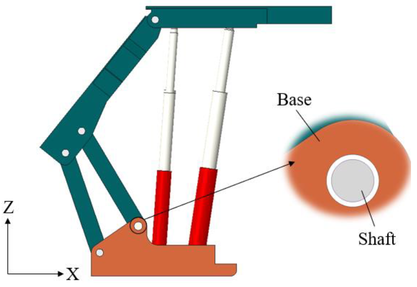
Based on the ideal mechanical analysis model of a hydraulic support, the ideal hinge point between the base and front connecting rod was invalidated, and a simulation shaft was added at the hinge point. To study the dynamic effects of different sizes of joint clearance on the hydraulic support, this can be realized by replacing simulation shafts with different diameters. In the ADAMS software, in order to simulate the rotation effect of the hinge point between the base and front connecting rod, the collision contact was set between the base, front connecting rod, and shaft. The hydraulic-support model with joint clearance is shown in Figure 2.
In most research on hydraulic supports, the research on joint clearance is mostly focused on kinematics analysis, and the movement of the shaft is planar. As shown in Figure 3a, the shaft only moves along the X–Z plane. In fact, because there are clearances between the base and shaft, and between the shaft and connecting rod, when the hydraulic support bears an offset load, the translation of the shaft only in the X–Z plane is no longer applicable. The shaft simulation method was adopted in this paper. The shaft has a certain movement space in all directions. As shown in Figure 3b, the contact mode between the connecting rod, shaft, and base can effectively simulate the state of the hinge point when the hydraulic support bears extreme loads.

2.3. Column Equivalent Model

In the loading stage of the hydraulic support, affected by roof settlement, the emulsion hydraulic shrinkage in the column is constantly changing, which leads to the dynamic change in column stiffness. In order to effectively simulate the variable-stiffness characteristics of the hydraulic-support column system, this paper proposes using the variable-stiffness spring-damping system to replace the column equivalently. Equation (4) is the equation for calculating the equivalent stiffness of a single-stage hydraulic-cylinder-sealing emulsion [24,25]. Table 1 shows the relevant parameters of the front- and rear-column hydraulic cylinders.
K C = A β L
where KC is the equivalent-stiffness coefficient of a single-stage hydraulic cylinder, N/m. A is the effective bearing area of the hydraulic-cylinder-bearing cavity, m2. β is the bulk modulus of elasticity of the working medium of the hydraulic cylinder, MPa, 1.95 × 10³ MPa. L is the length of the closed liquid column in the bearing chamber of the hydraulic cylinder, m.
According to Equation (4) and Table 1, the equivalent stiffness of the first-stage cylinder of the front column is 1.25 × 10⁸ N/m, the equivalent stiffness of the secondary cylinder is 6.42 × 10⁷ N/m, the equivalent stiffness of the primary cylinder of the rear column is 7.55 × 10⁷ N/m, and the equivalent stiffness of secondary cylinder is 3.95 × 10⁷ N/m. When the load outside the hydraulic support is not higher than the initial support force, the column height remains unchanged. When the load gradually increases but is not higher than the pressure in the primary cylinder, the secondary cylinder is gradually compressed with the increase in load, and the overall stiffness of the column is the equivalent stiffness of the secondary cylinder. When the force is higher than the pressure in the primary cylinder, the primary cylinder and secondary cylinder are compressed at the same time, and the equivalent stiffness is the parallel stiffness of the primary and secondary cylinders [26].
Equation (5) is the stiffness calculation equation for the parallel connection of the primary and secondary cylinders:
k = k a × k b k a + k b
where k is the column parallel stiffness, kN/mm. ka is the equivalent stiffness of the primary hydraulic cylinder of the column, kN/mm. kb is the equivalent stiffness of the secondary hydraulic cylinder of the column, kN/mm. According to the above column working principle and stiffness calculation method, by analyzing the column-stiffness characteristics at different heights, the variable-stiffness curve of the column was obtained and the equivalent spring-damping system was assigned.

3. Results

3.1. Action Mode of Impact Load

In order to study the impact load on the performance of the hydraulic support, the initial state of the hydraulic support was set as the ideal working state in this paper. Therefore, 14,000 kN static load (F in Figure 4) was applied in the load-balance area of the top beam to simulate the initial setting state of the hydraulic support. On this basis, in order to compare the bearing characteristics of the support under different loads more clearly, three loading points were, respectively, set at the front end and tail end of the top beam, as shown in Figure 4. The center loading point simulated the longitudinal torque of the hydraulic support, and the loading points on both sides simulated the horizontal and longitudinal loads of the hydraulic support. The loading function of static load F was step (time, 0, 0, 1, 14,000,000), and the loading function of impact dynamic load was step (time, 2, 0, 2.05, 600,000).

3.2. Posture Analysis of Hydraulic Support under Impact Load

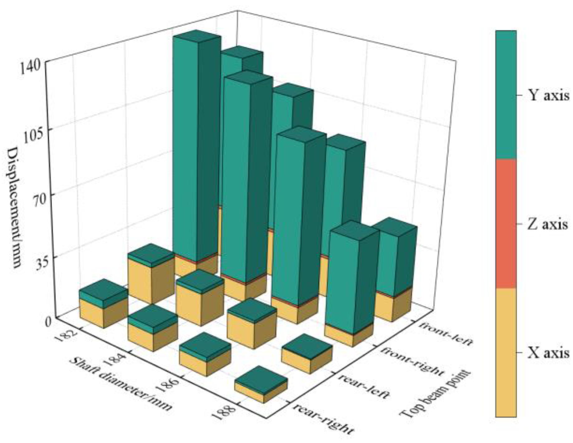
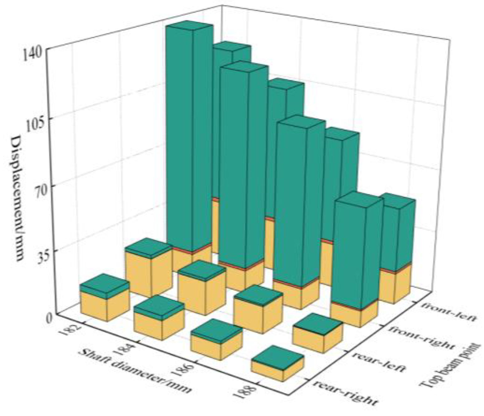
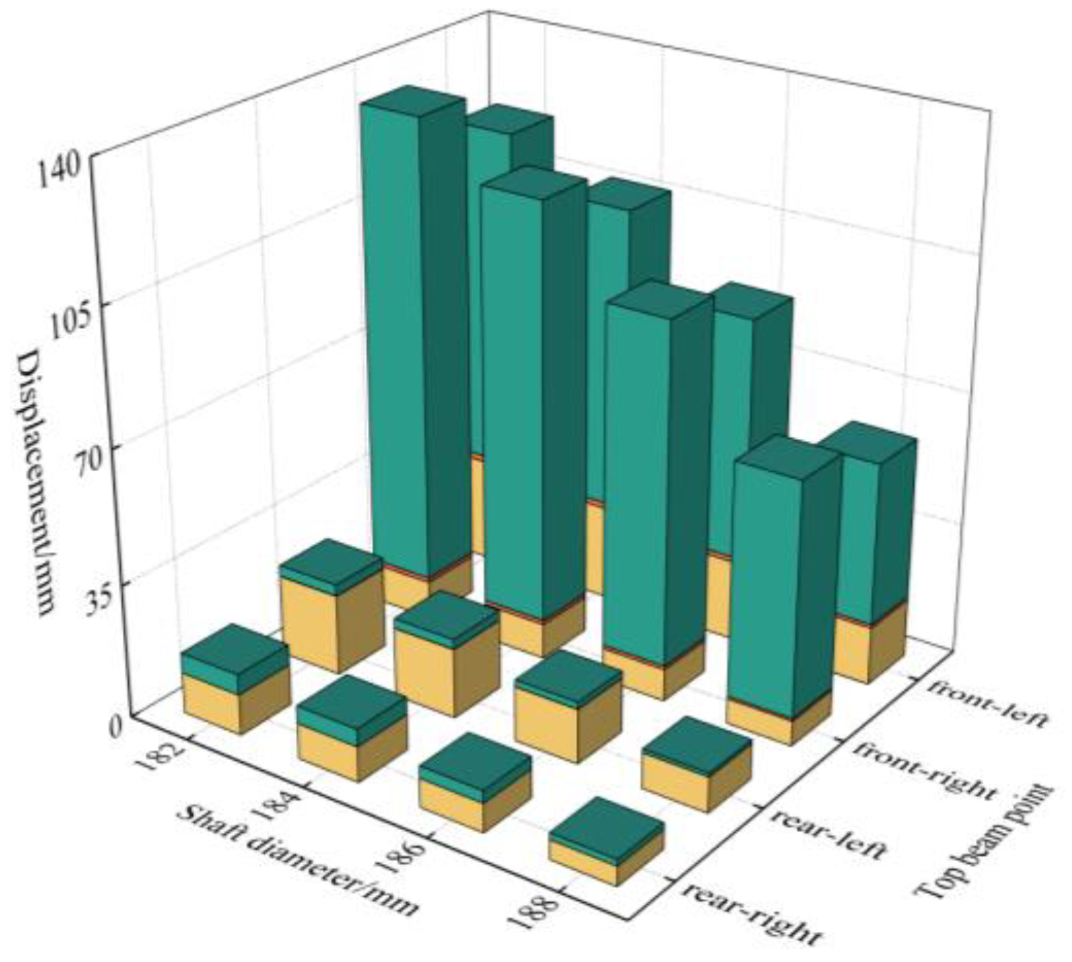
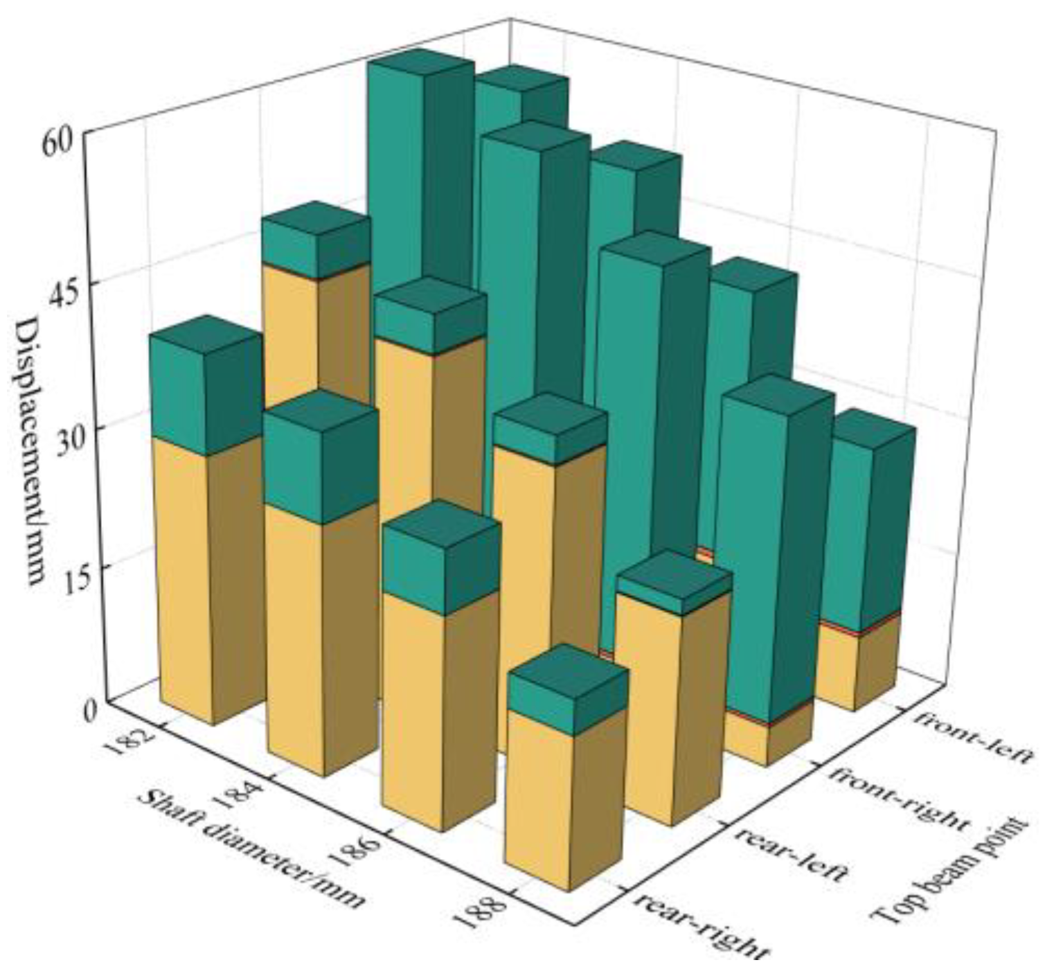
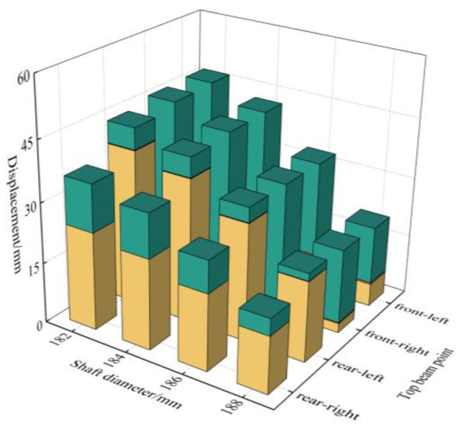
In order to intuitively express the influence of joint clearance on the support posture, the displacement data of the top-beam coordinate points were integrated into a stack diagram. In the diagram, the shaft diameter is taken as the horizontal axis, the coordinate point position is the longitudinal axis, and the coordinate point displacement is the vertical axis. The total height of the stack column represents the total displacement of the coordinate point compared with the ideal support. The data are composed of three parts: the brown color represents the displacement component of the coordinate point compared with the Y-axis of the ideal support, the grass-green represents the Z-axis displacement component compared with the ideal support, and the light blue represents the X-axis displacement component compared with the ideal support. By analyzing and comparing the displacement simulation results in all directions, the change in the top-beam posture can be obtained intuitively. In order to facilitate a comparison, the ratio of each displacement component of the coordinate point to the overall displacement is called the position movement ratio (PMR) in this section.

3.2.1. Impact Load Acts on the Front End of Double-Clearance-Support Top Beam

The displacement data of the coordinate point when the impact load acted on the front middle part of the top beam are shown in Figure 5. Along the decreasing direction of the shaft diameter, the overall displacement of the coordinate point showed a linear growth trend, in which the displacement of the X-axis grew the fastest. The displacement of the X-axis at the front end of the top beam increased from 27.28 mm to 81.74 mm, and the maximum PMR was 92.9%. The displacement of the X-axis at the rear end of the top beam increased from 14.45 mm to 50.99 mm, and the maximum PMR was 99.7%. The Z-axis displacement of the coordinate point at the front end of the top beam increased from 2.07 mm to 6.57 mm, and the maximum PMR was 7.4%, while the Y-axis displacement of each point on the top beam did not change significantly, and the maximum displacement was only 0.03 mm.
The displacement data of the coordinate point when the impact load offset acted on the front end of the top beam are shown in Figure 6. With the increase in joint clearance, the overall displacement of the coordinate points showed a linear growth trend. The development trend in the displacement of the X and Z axes of the coordinate points was similar to that of the central front loading of the top beam, but the total displacement on both sides of the top beam was slightly different. The maximum difference in the total displacement of the coordinate points on both sides was 2.20 mm. The displacement of the Y-axis at the front end of the top beam decreased from 1.91 mm to 0.62 mm, and the maximum PMR was only 6.5% at the minimum clearance.
By comparing the two working conditions of the top-beam offset and center loading in Figure 5 and Figure 6, it was found that when there was joint clearance at the support base, the top-beam X-axis displacement was obvious under the front load of the top beam, and the support was prone to forward tilting. Compared with the middle part of the impact load, the Y-axis displacement of the front end of the top beam was slightly increased, and the total displacement of the coordinate points on both sides of the top beam was slightly different. In conclusion, in terms of hydraulic-support posture, the sensitivity of the offset load to joint clearance was low.

3.2.2. Impact Load Acting on the Tail End of Double-Clearance-Support Top Beam

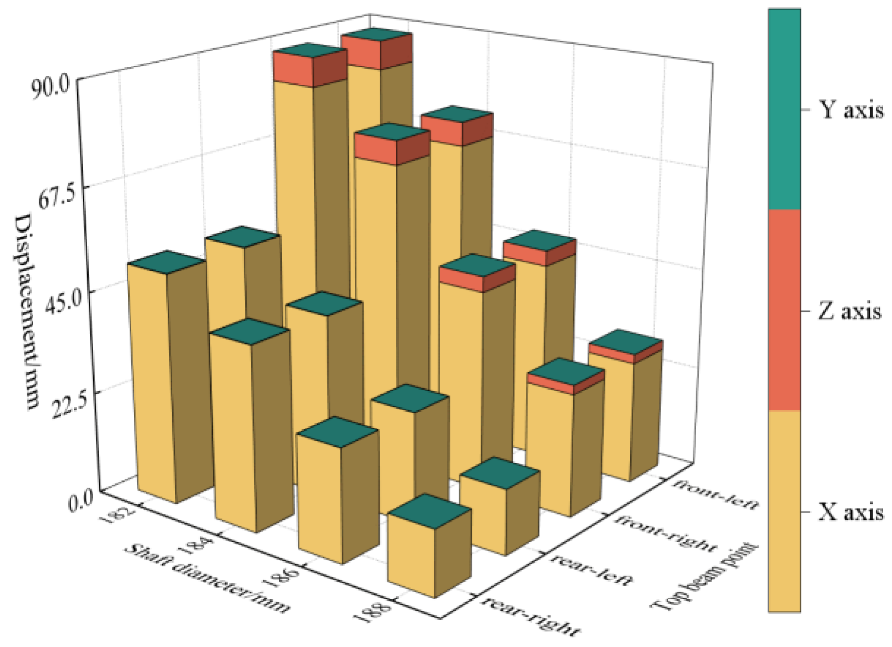
The displacement data of the coordinate point when the impact load acted on the middle back of the top beam are shown in Figure 7. Along the decreasing direction of the shaft diameter, the overall displacement of the coordinate point showed a linear growth trend. The Z-axis displacement of the coordinate point at the front end of the top beam increased from 15.27 mm to 48.37 mm, and the maximum PMR was 92.7%. The Z-axis displacement of the coordinate point at the rear end of the top beam increased from 35.73 mm to 85.20 mm, and the maximum PMR was 99.8%. The Z-axis displacement of the coordinate point at the front end of the top beam increased slowly from 0.07 mm to 3.95 mm, and the maximum PMR was 7.6%. The Y-axis displacement of each coordinate point of the top beam had no obvious change, and the maximum displacement was 0.002 mm.
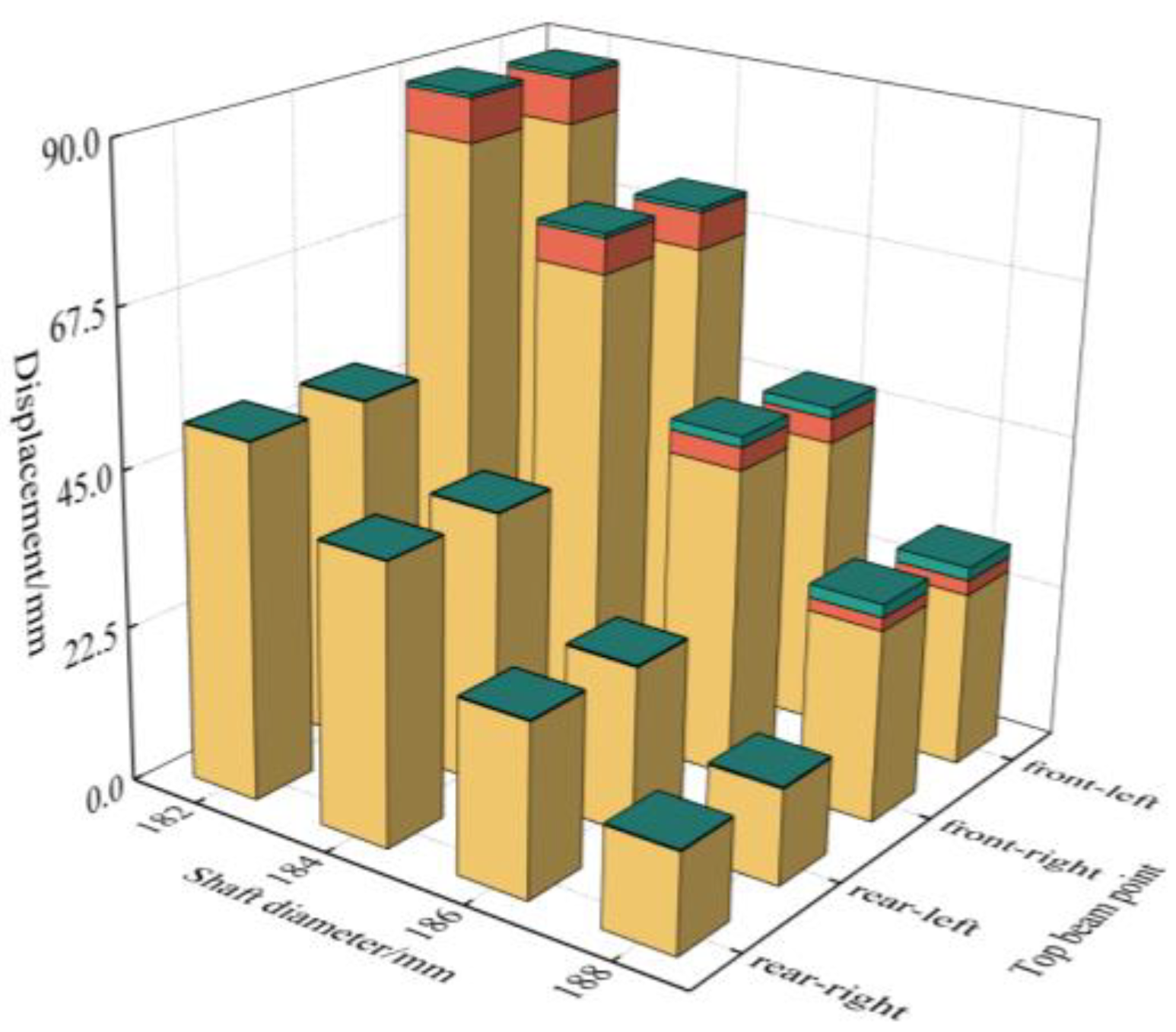
The displacement data of the coordinate point when the impact load offset acted on the tail end of the top beam are shown in Figure 8. With the expansion in the joint clearance, the overall displacement of the top-beam coordinate points showed a certain growth trend. There was a small difference in the displacement of the coordinate points on both sides of the top beam, and the maximum difference between the two sides was 1.01 mm. The X-axis displacement of each point showed a linear growth trend along the direction of shaft-diameter reduction. The displacement of the coordinate points on the left side of the top beam increased from 34.62 mm to 84.42 mm, and the maximum PMR was 99.5%. Along the increasing direction of joint clearance, the displacement of the Y-axis at the front end of the top beam first increased and then decreased from 0.42 mm to 1.10 mm and then decreased to 0.43 mm; the maximum PMR was only 2.6%.
By comparing the two loading conditions of the front end and the rear end of the top beam, it was found that the maximum displacement position was related to the position where the impact load was applied, and the position where the Z-axis displacement changed significantly was not related to the position where the load was applied, which were all located at the coordinate point at the front end of the top beam, and the displacement contribution in the Y and Z directions of the coordinate point was small. It can be seen that when there was clearance between hinge points on both sides of the base, the impact load at the top beam caused the hydraulic support to tilt forward, and joint clearance was less sensitive to additional offset load.

3.2.3. Impact Load Acts on the Front End of Single-Clearance-Support Top Beam

Because the load on the hydraulic support is usually not symmetrical, the contact loads of hinge points on both sides of the hydraulic support will be different, which leads to the inconsistent wear of shafts on both sides of the hydraulic support. In order to consider the influence of the different wear degrees of shafts on both sides on the support posture, a unilateral clearance model of the support hinge point was established in this study, and the model load setting is the same was the bilateral clearance model.
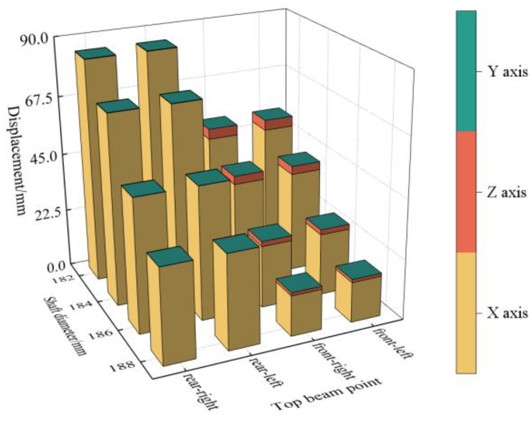
According to Figure 9, when impact load acted on the front middle part of the top beam, the total displacement of the top-beam coordinate points increased along the decreasing direction of the shaft diameter, and the growth rate was fast at first and then slow. The displacement of the Y-axis at the front end of the top beam was the largest, the displacement at the right side of the front end increased from 52.29 mm to 126.07 mm, the maximum PMR was 90.8%; the displacement at the left side of the front end increased from 34.76 mm to 91.13 mm, and the maximum PMR was 74.1%. The X-axis displacement on the right side of the front end of the top beam developed slowly with the horizontal axis, the displacement increased from 6.70 mm to 11.46 mm, and the maximum PMR was 11.2%. The X-axis displacement on the left side of the front end increased significantly with the horizontal axis, the displacement increased from 14.10 mm to 29.91 mm, and the maximum PMR was 28.3%. The Z-axis displacement at the coordinate point accounted for the lowest proportion, and the maximum displacement at each point was only 1.49 mm. The total displacement at the tail end of the top beam was smaller, and the maximum value was 24.81 mm. The X-axis displacement accounted for the highest proportion, and the maximum PMR was 89.2%.
The displacement data of the coordinate point when the impact load acted on the left front end of the top beam are shown in Figure 10. With the expansion of the joint clearance, the total displacement of the coordinate point tended to rise, and the rising trend was fast at first and then slow. The total displacement of the right front end of the top beam increased from 65.12 mm to 139.41 mm, of which the Y-axis displacement accounted for the highest proportion, and the maximum PMR was 89.3%. The total displacement of the left front end of the top beam increased from 53.97 mm to 121.82 mm, of which the X-axis displacement accounted for a significantly higher proportion than the right-side loading; the maximum PMR was 32.1%. The Z-axis displacement of the front end of the top beam accounted for a relatively small proportion; the maximum displacement was only 2.14 mm. The changing trend in the total displacement of the tail end of the top beam along the transverse axis was linear, and its change trend was similar to that of the front middle load.
The coordinate point displacement data when the impact load acted on the right front end of the top beam are shown in Figure 11. Along the decreasing direction of the shaft diameter, the overall displacement of the coordinate point showed a linear growth trend. The displacement of the right front end of the top beam increased from 61.28 mm to 121.68 mm, and the maximum PMR was 91.5%; the displacement of the left front end increased from 42.56 mm to 89.77 mm, and the maximum PMR was 75.3%. The development trend in X-axis displacement at the tail end of the top beam was similar to that of the front end. The displacement at the right front end of the top beam increased from 5.14 mm to 10.79 mm, and the maximum PMR was 74.7%. The displacement at the left front end of the top beam increased from 9.39 mm to 21.46 mm, and the maximum PMR was 90.2%.
By comparing Figure 9 with Figure 10 and Figure 11, it was found that when there was a clearance difference on both sides of the hydraulic-support hinge point, the impact dynamic load at the top beam made the lateral displacement of the front coordinate point too large, while the lateral-displacement change at the tail end of the top beam was weak, and the X axis displacement on both sides was significantly different, which resulted in the extreme torsional posture of the support top beam.

3.2.4. Impact Load Acts on the Tail End of Single-Clearance-Support Top Beam

According to Figure 12, when the impact load acted on the middle and rear part of the top beam, the displacement of the X and Y axis of the top beam increased with the increase in joint clearance, and the growth rate was first fast and then slow, while the displacement of the Z-axis of the top beam was minimum and change was not obvious. Among the displacement of the front end of the top beam, the Y-axis displacement of the right front end increased from 22.87 mm to 46.41 mm, and the maximum PMR was 90.2%. The Y-axis displacement of the left front end increased from 16.35 mm to 36.86 mm, and the maximum PMR was 73.4%. In the displacement of the end of the top beam, the X-axis accounted for the highest proportion. The Y-axis displacement of the right rear end of the top beam increased from 16.37 mm to 27.08 mm; the maximum PMR was 84.8%. The Y-axis displacement of the left rear end of the top beam increased from 21.19 mm to 41.15 mm; the maximum PMR was 92.1%.
According to Figure 13, when the impact load acted on the left rear end of the top beam, compared with the middle load, the total displacement of the front end of the top beam increased significantly. The total displacement of the right front end of the top beam increased from 37.35 mm to 61.00 mm, and the maximum PMR of the Y-axis was 89.66%; the displacement of the left front end of the top beam increased from 29.16 mm to 56.32 mm, the maximum PMR of the Y-axis is 72.6%, and the maximum difference between the displacements of both sides of the top beam reached 8.19 mm. Along the horizontal axis, the overall displacement of the tail end of the top beam showed a certain growth trend, of which the growth trend along the Y axis was the most significant, with the X-axis displacement accounting for the highest proportion. The Y-axis displacement of the right rear end of the top beam increased from 3.67 mm to 10.53 mm, and the maximum PMR was 26.5%. The Y-axis displacement of the left coordinate point of the tail end of the top beam increased from 1.64 mm to 4.58 mm, and the maximum PMR was 9.5%.
The displacement data of the top beam are shown in Figure 14 for when the impact load acted on the right rear end of the top beam. Compared with Figure 13 and Figure 4, the impact load on the right rear end made the displacement on both sides of the top beam tend to balance, but the proportion of displacement in different directions was different. The displacement of the right front end increased from 20.98 mm to 45.95 mm, the PMR in the Y direction increased from 87.4% to 90.6%, the displacement of the left front end increased from 20.34 mm to 46.39 mm, and the PMR in the Y direction increased from 70.0% to 74.3%. The displacement of the X and Y axes at the tail end of the top beam showed an upward trend, while the displacement of the Z-axis was the smallest; the maximum displacement of the Z-axis was 0.17 mm, and the PMR was only 11.2%. However, the displacement of the X-axis at the left front end increased significantly with the horizontal axis, from 14.10 mm to 29.91 mm, and the maximum PMR was 0.4%.
By comparison with Figure 13 and Figure 14, the displacement trends in each direction at the tail end were similar. When the impact load acted on the side with clearance, the displacement of the coordinate point increased, and the lateral torsion at the front end of the top beam increased. When the impact load acted on the side without clearance, the displacement of the coordinate point slowed down along the horizontal axis compared with the tail-end load, and the total displacement was lower than the side with clearance. It can be seen that when there was a clearance difference between the two sides of the support, the resistance of the support to impact load was greatly weakened. Compared with the clearance between the two sides of the support with no clearance difference, the top beam of the support was laterally offset to a certain extent after being loaded, and the height difference between the two sides of the top beam was large, so the top beam presented a torsional-bearing posture.

3.3. Dynamic Analysis of Hydraulic Support with Clearance

3.3.1. Mechanical Analysis of the Hinge Point between the Top Beam and Shield Beam

In order to study the mechanical-response characteristics of a hydraulic support when there is a clearance in the base, a mechanical-analysis model of the unilateral clearance of the hydraulic support was established, and the ratio of load-change value of the hinge point under the single-clearance condition to the load under the ideal state was taken as the load-floating coefficient. On this basis, the bearing state of the support at different hinge positions was analyzed.
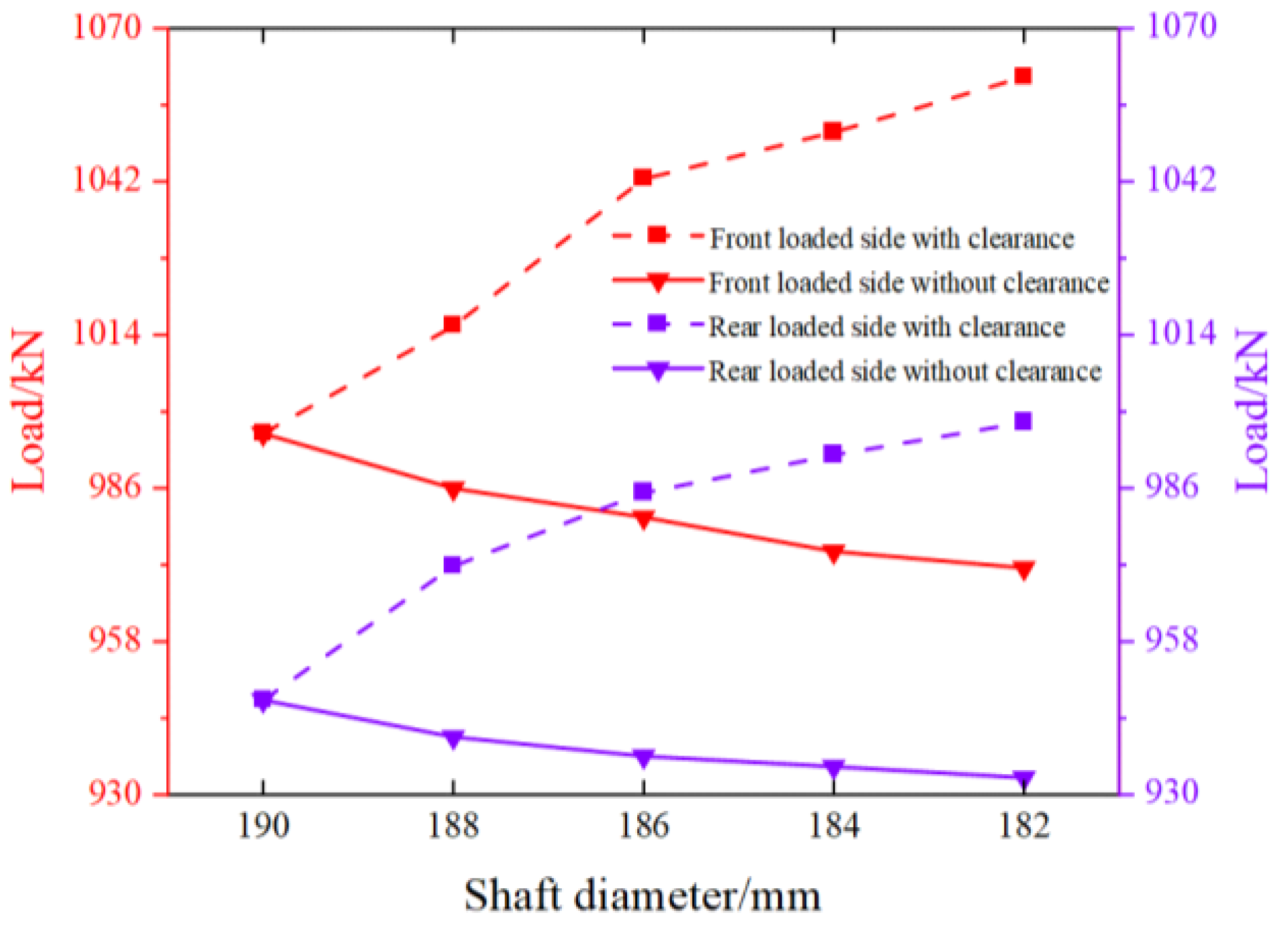
Observe the load-change diagram of the hinge point between the top beam and shield beam in Figure 15. For the same loading mode, the load of the hinge point on the side with clearance of the hydraulic support was higher than that on the side without clearance, and the load difference on both sides increased with the increase in clearance. Along the abscissa direction, the load on the side with clearance of the hydraulic support tended to increase, and the increase was fast at first and then slow. The load on the side without clearance of the hydraulic support tended to decrease, and the decrease was relatively stable. Comparing the two load cases of the front end and the tail end of the top beam, when the front end of the top beam was loaded, the load of each hinge point was significantly higher than the load case of the tail end, and the load difference between different clearances was almost the same.

3.3.2. Mechanical Analysis of the Hinge Point between the Base and Front Connecting Rod

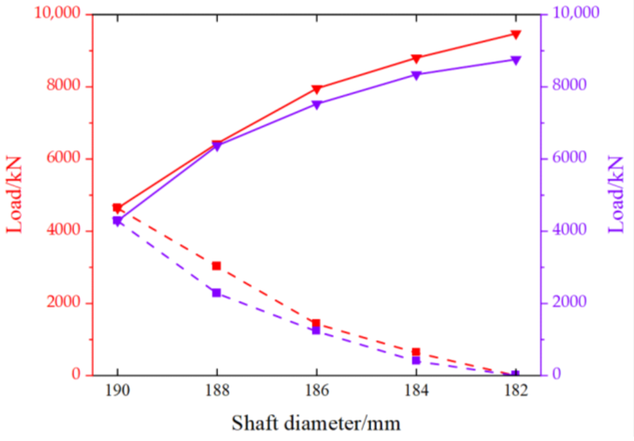
According to Figure 16, the load-bearing-change diagram of the hinge point between the base and front connecting rod, along the change direction of the axis-shaft diameter of the abscissa, the load on the side of the hydraulic support without clearance generally showed an upward trend, but the load growth rate gradually decreased, with the maximum load increment reaching 4837.5 kN and the load-floating coefficient being 1.04; the load on the side of clearance generally showed a downward trend, and the load-weakening rate gradually decreased, with the maximum load increment being −4640 kN and the load-floating coefficient reaching −1. Observe the loading conditions of the front end and tail end of the top beam. Along the change direction of the shaft diameter, the front half of the bearing curve of the hinge point at the side with clearance is different. The rear half is more closely fitted. The front half of the bearing curve at the side without clearance is closely fitted and the rear half is separated. The mechanical-response curve under the loading conditions of the front end of the hydraulic support is higher than the tail-end loading.

3.3.3. Mechanical Analysis of Hinge Point between Base and Rear Connecting Rod

According to Figure 17, the load-change diagram of the hinge point at the base rear-connecting rod, along the change direction of the shaft diameter, the load on the side of the hydraulic support without clearance generally showed an upward trend, but the load growth rate gradually decreased. The maximum load-floating coefficient was 0.92, the load on the side of the hydraulic support with clearance generally showed a downward trend, the load-weakening speed gradually decreased, and the minimum load-floating coefficient is −0.87.
Through the analysis of the load change of the hinge point at the base in Figure 16 and Figure 17, compared with the hinge point of the rear connecting rod, the load-change speed of the hinge point at the front connecting rod was slightly higher, and the load on the side with clearance returned to zero when the shaft diameter was 182 mm, while the load on the side without clearance reached 9477.5 kN. Therefore, the joint clearance on the hydraulic support will lead to the uneven distribution of the load on both sides of the support, and this working condition will increase working pressure on the side with a smaller clearance. In the simulation experiment, the maximum load-fluctuation coefficient could reach 1.04, which could lead to the failure of the support and endanger the safety of the working face.

4. Discussion

This paper innovatively considered the difference in the size of joint clearance on both sides of the hydraulic support and studied the impact on the characteristics of the hydraulic support in this case. In the analysis of the hydraulic-support posture, not only the changing trend in the overall displacement was considered, but also the displacement proportion of each direction was analyzed. The specific conclusions are as follows:
(1) When the hydraulic support has joint clearance on both sides, when the top beam bears the impact load, the total displacement difference on both sides of the top beam is small, the displacement at the impact-load position is the highest, and the PMR of the top beam in the X-axis direction is more than 80%. The displacement in the Y-axis direction is small, while the maximum displacement of the Z-axis is at the front of the top beam, which has little relationship with the impact-load action position. Therefore, the impact load at the top beam will cause a forward-tilt posture of the hydraulic support, while the additional offset load has little effect on the posture of the top beam.
(2) For the hydraulic support with unilateral joint clearance, when the impact load acts on the front end of the top beam, the front-end displacement of the top beam is about four times the rear-end displacement, where the front-end displacement is mainly in the Y direction and the rear end is mainly in the X direction. Compared with the support without clearance, the total displacement of the side with clearance at the front end of the top beam is lower, while the total displacement of the side with clearance at the rear end of the top beam is higher, which indicates that the front-end impact dynamic load causes the excessive lateral displacement of the front end; however, the lateral-displacement change of the tail end is weak, and the X direction displacement of both sides of the top beam is obviously different.
(3) For the hydraulic support with unilateral joint clearance, when the impact load acts on the tail end of the top beam, the Z-direction PMR of the top beam is less than 1%, and the total displacement difference of each point is small. When the impact load acts on one side of clearance, the displacement gap between the two sides of the top beam increases, and the front-end displacement increases. When the impact load acts on the side without clearance, the displacement slows down with the increase in hinge-joint clearance, and the total displacement is lower than the side with clearance. Therefore, compared with the ideal support, the single-clearance support has a certain degree of lateral displacement after loading, and the main offset directions on both sides of the top beam are inconsistent, which makes the top beam present a torsional-bearing posture.
(4) For the single-clearance hydraulic support, when the front end of the top beam is loaded, the load on each hinge point is higher than the load on the tail end. With the increase in joint clearance, the support base gradually becomes a one-sided bearing, the maximum load-fluctuation coefficient of the hinge point on the loaded side reaches 1.04, and the load fluctuation coefficient on one side of clearance reaches the minimum value of −1, which makes the hinge point on one side of the support clearance unable to play a supporting role. This will lead to the concentrated load on one side of the hydraulic support and endanger the safety of the coal-mining face.
In this paper, a numerical model of a hydraulic support with joint clearance is established. Under different loading conditions, the influence of clearance on the attitude and dynamic characteristics of the hydraulic support is analyzed. The results show that the hydraulic support is prone to tilting forward when there is bilateral joint clearance. When there is unilateral joint clearance, the top beam of the hydraulic support is easy to twist, and the bearing capacity of the support is weakened. However, the actual working environment of the hydraulic support is relatively complex, and it is one-sided to consider the situation where only one hinge point has clearance. In the future, we will study the situation where different hinge points have clearance, and consider that when multiple hinge points have clearance, this has an influence on the bearing characteristics of the hydraulic support.

Author Contributions

Conceptualization, Z.M. and Q.Z.; methodology, P.X.; software, P.X.; validation, Z.M., P.X. and C.M.; formal analysis, P.X.; investigation, X.L.; resources, Q.Z. and Z.M.; data curation, P.X.; writing—original draft preparation, P.X.; writing—review and editing, P.X. and Z.M.; visualization, P.X.; project administration, Z.M. All authors have read and agreed to the published version of the manuscript.

Funding

This research was funded by the National Natural Fund (Grant No.52104164 and 52274132) and the Natural Science Foundation of Shandong Province (Grant No.ZR2020QE103).

Data Availability Statement

Not applicable.

Conflicts of Interest

The authors declare no conflict of interest.

References

  1. Du, Y. Supporting Condition Acquisition and Fuzzy Comprehensive Evaluation Method for Hydraulic Support. J. China Coal Soc. 2017, 42 (Suppl. S1), 260–266. [Google Scholar]
  2. Kang, H.; Wang, G.; Jiang, P.; Wang, J.; Zhang, N.; Jing, H.; Huang, B.; Yang, B.; Guan, X.; Wang, Z. Conception for Strata Control and Intelligent Mining Technology in Deep Coal Mines with Depth More than 1000 m. J. China Coal Soc. 2018, 43, 1789–1800. [Google Scholar]
  3. Yan, S.; Xu, G.; Fan, Z. Development Course and Prospect of the 50 Years’ Comprehensive Mechanized Coal Mining in China. Coal Sci. Technol. 2021, 49, 1–9. [Google Scholar]
  4. Frith, R.C. A Holistic Examination of the Load Rating Design of Longwall Shields after More than Half a Century of Mechanised Longwall Mining. Int. J. Min. Sci. Technol. 2015, 25, 687–706. [Google Scholar] [CrossRef]
  5. Wang, G.; Pang, Y.; Li, M.; Ma, Y.; Liu, X. Hydraulic Support and Coal Wall Coupling Relationship in Ultra Large Height Mining Face. J. China Coal Soc. 2017, 42, 518–526. [Google Scholar]
  6. Pan, J.; Qi, Q.; Liu, S.; Wang, S.; Ma, W.; Kang, X. Characteristics, Types and Prevention and Control Technology of Rock Burst in Deep Coal Mining in China. J. China Coal Soc. 2020, 45, 111–121. [Google Scholar]
  7. Bao, Y. Research on Intelligent Control Key Technology of Fully Mechanized Top Coal Caving Face in Extra Thick Coal Seam. Coal Sci. Technol. 2020, 48, 55–61. [Google Scholar]
  8. Liang, L.; Tian, J.; Zheng, H.; Jiao, S. A Study on Force Transmission in a Hydraulic Support under Impact Loading on Its Canopy Beam. J. China Coal Soc. 2015, 40, 2522–2527. [Google Scholar]
  9. Ren, H.; Zhang, D.; Gong, S.; Zhou, K.; Xi, C.; He, M.; Li, T. Dynamic Impact Experiment and Response Characteristics Analysis for 1:2 Reduced-Scale Model of Hydraulic Support. Int. J. Min. Sci. Technol. 2021, 31, 347–356. [Google Scholar] [CrossRef]
  10. Szurgacz, D.; Brodny, J. Analysis of the Influence of Dynamic Load on the Work Parameters of a Powered Roof Support’s Hydraulic Leg. Sustainability 2019, 11, 2570. [Google Scholar] [CrossRef] [Green Version]
  11. Szurgacz, D.; Brodny, J. Tests of Geometry of the Powered Roof Support Section. Energies 2019, 12, 3945. [Google Scholar] [CrossRef] [Green Version]
  12. Guan, E.; Miao, H.; Li, P.; Liu, J.; Zhao, Y. Dynamic Model Analysis of Hydraulic Support. Adv. Mech. Eng. 2019, 11, 1687814018820143. [Google Scholar] [CrossRef] [Green Version]
  13. Witek, M.; Prusek, S. Numerical Calculations of Shield Support Stress Based on Laboratory Test Results. Comput. Geotech. 2016, 72, 74–88. [Google Scholar] [CrossRef]
  14. Erkaya, S. Effects of Joint Clearance on the Motion Accuracy of Robotic Manipulators. J. Mech. Eng. 2018, 64, 82–94, 13p. [Google Scholar]
  15. Chen, X.; Fan, H. Dynamic Modeling and Response Analysis of Spatial Parallel Mechanism Considering Lubrication Clearance of Spherical Joints. Eur. J. Mech. A/Solids 2022, 92, 104458. [Google Scholar] [CrossRef]
  16. Hou, Y.; Deng, Y.; Zeng, D. Dynamic Modelling and Properties Analysis of 3RSR Parallel Mechanism Considering Spherical Joint Clearance and Wear. J. Cent. South Univ. 2021, 28, 712–727. [Google Scholar] [CrossRef]
  17. Zhao, H.; Wang, J.; He, F.; Yu, D.; Wen, H. Design of Virtual Simulation Teaching Experiment for the Dynamics Analysis of Reciprocating Mechanism with Joint Clearance. Exp. Technol. Manag. 2022, 39, 162–166. [Google Scholar]
  18. Matekar, S.B.; Fulambarkar, A.M. Displacement Analysis of Slider in Slider-Crank Mechanism with Joint Clearance. Aust. J. Mech. Eng. 2020, 20, 949–958. [Google Scholar] [CrossRef]
  19. Feng, B.Z.; Xin, J.; Fei, L.; Jun, Z.J.; Yang, Z. Reducing Undesirable Vibrations of Planar Linkage Mechanism with Joint Clearance. J. Mech. Sci. Technol. 2018, 32, 559–565. [Google Scholar]
  20. Qingliang, Z.; Yangyang, L.; Yang, Y. Dynamic Analysis of Hydraulic Support with Single Clearance. Stroj. Vestn. J. Mech. Eng. 2021, 67, 53–66. [Google Scholar]
  21. Wang, X.; Cui, T.; Xie, J.; Shen, H.; Liu, Y.; Wang, B. Virtual Simulation Method of Hydraulic Support Motion Considering Pin Shaft Clearance. Coal Sci. Technol. 2021, 49, 186–193. [Google Scholar]
  22. Su, Y.; Guo, C.; Chen, W. Applicability Analysis of Internal Cylindrical Contact Model with Micro Clearance in Multibody System. Lubr. Eng. 2020, 45, 106–113. [Google Scholar]
  23. Jing, Q.; Liu, H. Dynamic Characteristics of Linkage Mechanism Considering Clearance of Cylinder Pair. J. Vib. Shock. 2021, 40, 32–39. [Google Scholar]
  24. Xu, W. Study on Load Characteristics of Hydraulic Support Column under Impact Load. Coal Mine Mach. 2021, 42, 63–66. [Google Scholar]
  25. Zeng, Q.L.; Meng, Z.S.; Wan, L.R.; Wang, C.L. Analysis on Force Transmission Characteristics of Two-Legged Shield Support under Impact Loading. Shock. Vib. 2018, 2018, 1–10. [Google Scholar] [CrossRef]
  26. Zeng, Q.; Xu, P.; Meng, Z.; Wan, L. Dynamic Response Analysis of Four Column Chock Shield Support under Impact Load. Coal Sci. Technol. Available online: https://kns.cnki.net/kcms/detail/11.2402.TD.20220926.1612.002.html (accessed on 31 December 2022).
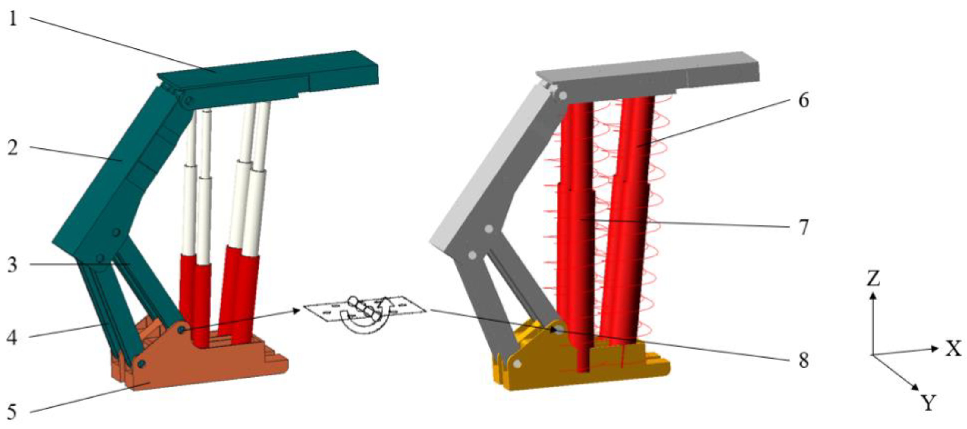
Figure 1. Rigid–flexible coupling model of hydraulic support. 1. Top beam 2. Shield beam 3. Front connecting rod 4. Rear connecting rod 5. Base 6. Front column 7. Rear column 8. Rotating pair.
Machines 11 00159 g001
Figure 2. Hydraulic support with clearance.
Machines 11 00159 g002
Figure 3. Rendering of simulated shaft. (a) Middle loading status; (b) Offset loading status.
Machines 11 00159 g003
Figure 4. Schematic diagram of top-beam coordinate points.
Machines 11 00159 g004
Figure 5. Impact load acting on the front end of the top beam.
Machines 11 00159 g005
Figure 6. Impact load offset acting on the front end of the top beam.
Machines 11 00159 g006
Figure 7. Impact load acting on the end of the top beam.
Machines 11 00159 g007
Figure 8. Impact load offset acting on the end of the top beam.
Machines 11 00159 g008
Figure 9. Impact load acting on the middle front end of the top beam.
Machines 11 00159 g009
Figure 10. Impact load acting on the left front end of the top beam.
Machines 11 00159 g010
Figure 11. Impact load acting on the right front end of the top beam.
Machines 11 00159 g011
Figure 12. Impact load acting on the middle end of the top beam.
Machines 11 00159 g012
Figure 13. Impact load acting on the left end of the top beam.
Machines 11 00159 g013
Figure 14. Impact load acting on the right end of the top beam.
Machines 11 00159 g014
Figure 15. Load change of hinge joint of top beam and shield beam.
Machines 11 00159 g015
Figure 16. Load change on hinge point of front connecting rod and base.
Machines 11 00159 g016
Figure 17. Load change of hinge point of rear connecting rod and base.
Machines 11 00159 g017
Table 1. Main parameters of the column.
Hydraulic CylinderDiameter of Hydraulic Cylinder/mmHydraulic Rod Diameter/mmEffective Liquid Column Length/mm
Front columnFirst-stage cylinder3903701 956
Second-stage cylinder2902602 006
Rear columnFirst-stage cylinder3353052 076
Second-stage cylinder2302102 052
Disclaimer/Publisher’s Note: The statements, opinions and data contained in all publications are solely those of the individual author(s) and contributor(s) and not of MDPI and/or the editor(s). MDPI and/or the editor(s) disclaim responsibility for any injury to people or property resulting from any ideas, methods, instructions or products referred to in the content.