Article

Investigating the Role of Stator Slot Indents in Minimizing Flooded Motor Fluid Damping Loss

Department of Electrical and Electronics Engineering, Abdullah Gul University, 38080 Kayseri, Türkiye
*
Author to whom correspondence should be addressed.
Machines 2023, 11(12), 1088; https://doi.org/10.3390/machines11121088
Submission received: 9 November 2023 / Revised: 5 December 2023 / Accepted: 12 December 2023 / Published: 14 December 2023
(This article belongs to the Section Electrical Machines and Drives)

Abstract

:
This research examines how fluid damping loss affects the operation of a two-pole, 5.5 HP (4 kW) induction machine (IM) within the context of different slot opening configurations developed for downhole water pump applications. Since these motors operate with their cavities filled with fluid, the variations in fluid viscosity and density, compared to air, result in the occurrence of damping losses. Furthermore, this loss can be attributed to the motor’s stator and rotor surface geometry, as the liquid within the motor cavity moves unrestrictedly within the motor housing. This study involves the examination of the damping loss in a 24-slot IM under different stator slot indentations. The investigation utilizes computational fluid dynamics (CFD) finite element analysis (FEA) and is subsequently validated through experiments. The aim of this work is to emphasize the significance of fluid damping loss in submerged machines. Results reveal that the damping loss exceeds 8% of the motor output power when the stator surface has indentations, and it diminishes to 3.2% of the output power when a custom wedge structure is employed to eliminate these surface indentations.

1. Introduction

In today’s world, there is a widespread objective to minimize energy losses, aimed at preserving natural resources and lowering energy expenses. As electric drive systems’ energy consumption accounts for 70% of the world’s energy, enhancing the efficiency of electric machines offers substantial advantages on both a national and global scale [1]. In the industrial sector, a significant share of electric motors is dedicated to pump motors, primarily employed to pump water and petroleum products from underground. Typically, machines utilized in flooded applications operate at notably low efficiencies due to various factors, including cost constraints, motor design challenges, and incorrect motor pump configurations. Nevertheless, owing to their robustness, cost-effectiveness, and being able to start with line voltage, Induction Machines (IMs) are often favored for pump applications.
In contrast to standard applications, flooded pump motors usually operate within environments filled with fluid. These machines are filled with fluids not only to prevent the water being pumped from infiltrating the motor but also to provide cooling. As a result, these motors run with both the stator and rotor submerged in fluid. Consequently, flooded motors experience fluid damping losses due to the damping effect of the fluids similar to air-filled machines’ windage losses [2,3]. The fluid damping effect is neglected in some pump motor design studies [4,5,6,7], where only the stator is flooded, or the motor is a dry motor [6,7]. In [8], a line start synchronous machine is designed ignoring the fluid damping effect, where the synchronization issues are explained with the overall moment of inertia for both the motor and the load being almost five times greater than the estimated value. Considering that the fluids are typically denser than the air and cause higher losses compared to the windage losses, it is imperative not to overlook the damping effect when designing the motor. Since the line start synchronous machines work as IMs during the start-up until they reach synchronous speed, the torque they generate around the synchronization speed is a crucial performance merit. If the damping loss is ignored during the design stage, the designed motor cannot overcome the total torque, which is the summation of load, friction, and damping torques along with the transient speed torque due to inertia. Consequently, the synchronization performance of line start synchronous machines may be impacted. In the existing literature, one can discover studies that consider damping losses and optimize designs accordingly [2,9,10,11]. In [9], a high-power density pump motor is designed by estimating the damping loss analytically. The estimated loss is deviated when calculated with the computational fluid dynamics method (CFD), and this deviation is explained by the temperature variation on the surface of the rotor. Similarly, a permanent magnet synchronous motor (PMSM) design study takes the damping effect into account using CFD [2]. Here, the air gap is modeled as a smooth cylindric surface. However, the calculated drag loss is deviated by 14% on experimental validation, which is related to the slotted structure of the stator. In [10], CFD is used to investigate the air gap thickness variation on fluid damping loss while designing a PM machine including eccentricity. In another study [11], a PM motor is designed for a turbine application where the fluid goes through the motor, i.e., the water travels through the air gap. Here, water comes into the motor through an inlet and slides through the rotor surface while the stator surface is closed with a container and goes out from the motor through an outlet. In such cases where water travels between a stationary cylinder and a rotating cylinder, vortices and turbulent flows are almost zero [12]. However, when surface nonidealities exist, the vortices and turbulent fluid flows increase and cause pressure variations in the air gap. Various studies indicate that the fluid viscosities increase with the pressure [13,14,15]. Considering a borewell flooded pump motor flooded with water, the inner pressure is dependent on how deep the motor is placed. The pressure increases 1 atm every 10 m, and usually the borewell flooded pump motors are placed 10 to 20 m deep. In [14], it is reported that the damping loss of a fluid doubles when the pressure varies from 0 to 80 mPa (798.54 atm). Also, the viscosity varies with the temperature. In [15], the relative viscosity variation of the water with respect to the pressure and temperature is investigated, and at room temperature, the viscosity variation of the water is reported as less than 1% when pressure changes from 0 to 300 atm. In [16,17], line start synchronous reluctance machines are designed as flooded water pump motors where the damping effect is reflected in the total loss calculation to obtain accurate performance metrics. However, results are not conducted with any experimental verification for either of the mentioned studies.
This study examines a two-pole, 5.5 HP (4 kW) IM designed for use as a flooded water pump motor. The research focuses on the analysis of fluid damping losses for various slot opening configurations using computational fluid dynamics (CFD), using distinct wedge structures, and not using any wedges. The main goal is to examine how various stator indentation configurations impact fluid damping and how this, in turn, affects damping losses in flooded electric motors.
The investigation is conducted to evaluate the impact of stator slot surface characteristics, specifically indented and smooth surfaces, on fluid damping loss. Firstly, the design where wedges are not used in the stator slots, which leads to a large indented area on the stator surface, is analyzed. Second, an analysis is conducted on the implementation of standard wedges in the slot openings. Despite the use of standard wedges, the presence of indents on the stator surface persists due to the larger slot openings common in flooded pump motors. During the final stage, the suggested custom wedge structure is implemented to seal all indentations and form a smooth surface on the stator, followed by an analysis of the resulting damping loss. A significant reduction is obtained while the motor is operating in steady state condition with the custom wedges. The analysis is also performed with air as a replacement for the fluid. In this comparison with fluid damping losses, windage losses are found to be exceedingly low and can be disregarded.
Later, two identical motors with their stator slots closed with custom and special wedges are built and tested experimentally. The CFD analysis and experimental test results exhibit a strong correlation, leading to the conclusion that fluid damping loss cannot be treated as equivalent to windage losses and should not be ignored in the context of flooded machines.
The subsequent sections of the paper are organized as follows: Section 2 provides contextual information regarding the impact of fluid damping. Section 3 outlines the CFD analysis and presents its results for various slot opening structures with differing stator surface indentations. In Section 4, details about the test setup, experimental results, and a discussion are provided. Finally, Section 5 provides a concise conclusion.

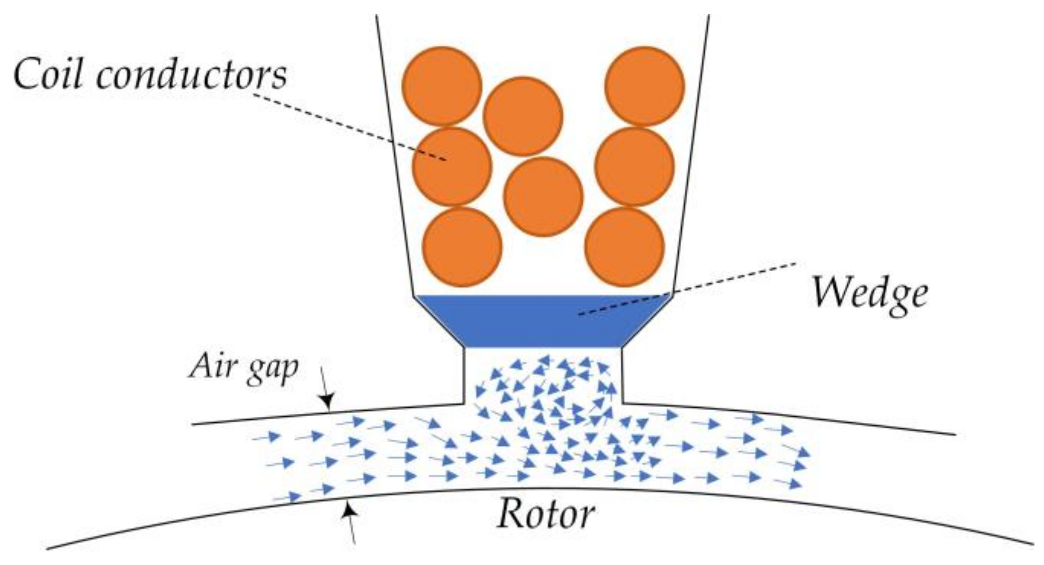
2. Fluid Damping Loss

Flooded motor rotors and stators are typically surrounded by a liquid, which is typically a combination of water and polypropylene glycol, or oil. When rotors move within this fluid, damping losses occur, similar in concept to the windage losses experienced by dry motors, which are in fact damping losses due to the filled air inside the machine. Increased density of the water mixture compared to air leads to an expectation of higher losses, surpassing the usual windage losses. The associated calculations are detailed below as in [18]:
P w = C d ρ π r 4 ω 3 L
where the damping loss is denoted as Pw in Watts, the coefficient of the skin friction is represented with Cd, fluid density is ρ (997 kg/m3 for water), r is the radius of the rotor, ω is the shaft speed in rad/s, and the length of the rotor is L. The calculation of the skin friction coefficient is performed with 2, where the shear stress on the rotor surface is represented with τd, the dynamic pressure is expressed with Pd, the rotor’s projected area is denoted with A, and the fluid velocity is represented with ν.
C d = τ d P d A
P d = 1 2 ρ ν 2
Typically, the Cd is determined empirically rather than through calculations [9,19]. In [20], the skin friction coefficient is calculated with the following expression.
1 C d = 2.04 + 1.768 ln R e C d
where the coefficients are determined empirically, and the Reynolds number, Re, is expressed as:
R e = ω r ρ μ ϕ
Here, µ is the dynamic viscosity of the fluid and ϕ is the air gap length. There exist additional empirical calculations using various approaches [19]. However, these approaches consider the air gap to be a smooth cylinder and completely ignore the specific geometric characteristics of the air gap surface. Moreover, the roughness of the rotor surface is considered as a not changing parameter, which varies for different rotors even if they are manufactured with the same machinery. The parameters, shear stress on the rotor surface and dynamic pressure, which are required for computing the skin friction coefficient, could only be acquired through numerical methods involving CFD analysis. In this research, various slot opening structures are examined, and the CFD analysis details are elaborated on in the next section.

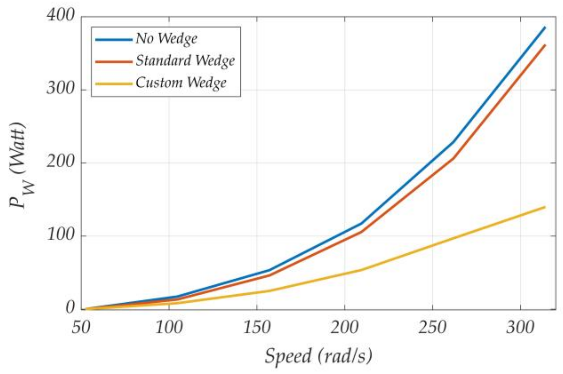
3. Damping Loss Analysis with Different Slot Opening Structures

Flooded pump motors typically feature magnet wires wound with Polyvinyl Chloride (PVC) insulation. PVC is chosen for its suitability in applications requiring electrical isolation in the presence of fluids. Its superior chemical stability compared to standard varnished magnet wire makes it a safe and appropriate choice for submerged environments. PVC-insulated wires have larger diameters than regular ones due to their thicker insulation. Consequently, the stator slot openings of these flooded pump motors are wider than those found in industrial motors. To close these expanded slot openings and secure the coils during operation, standard slot wedges are employed. However, when these wedges are not precisely custom-fitted, they produce a surface with indentations on the stator’s air gap side. This indented structure leads to increased liquid fluctuations, as depicted in Figure 1, ultimately resulting in significantly increased pressure differences and damping losses.
In this study, the investigation into damping loss is conducted through the utilization of CFD analysis. This analysis considers three distinct designs: one without a wedge, another with a standard wedge, and a third featuring a custom no-slotting wedge structure. The CFD analysis is configured with the stator surface designated as the stationary element, while the rotor is described as a smooth-surfaced cylinder rotating at a specified speed. The liquid within the air gap cavity is specified as water at 20 °C with no initial velocity. Analysis results are obtained once the system reaches a steady state operational condition. All CFD analyses are conducted within the ANSYS/Fluent simulation environment. Key motor parameters are outlined in Table 1.

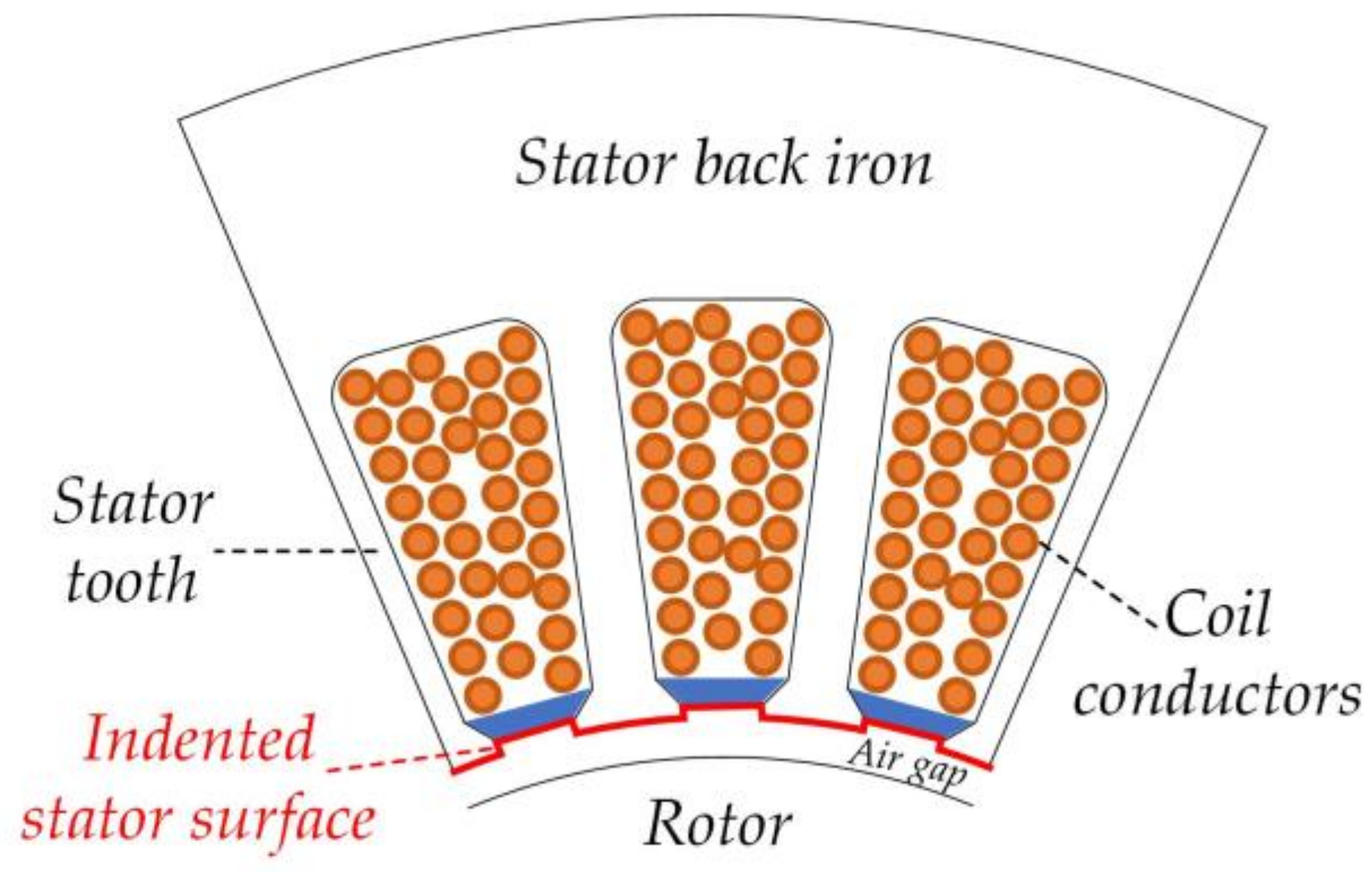
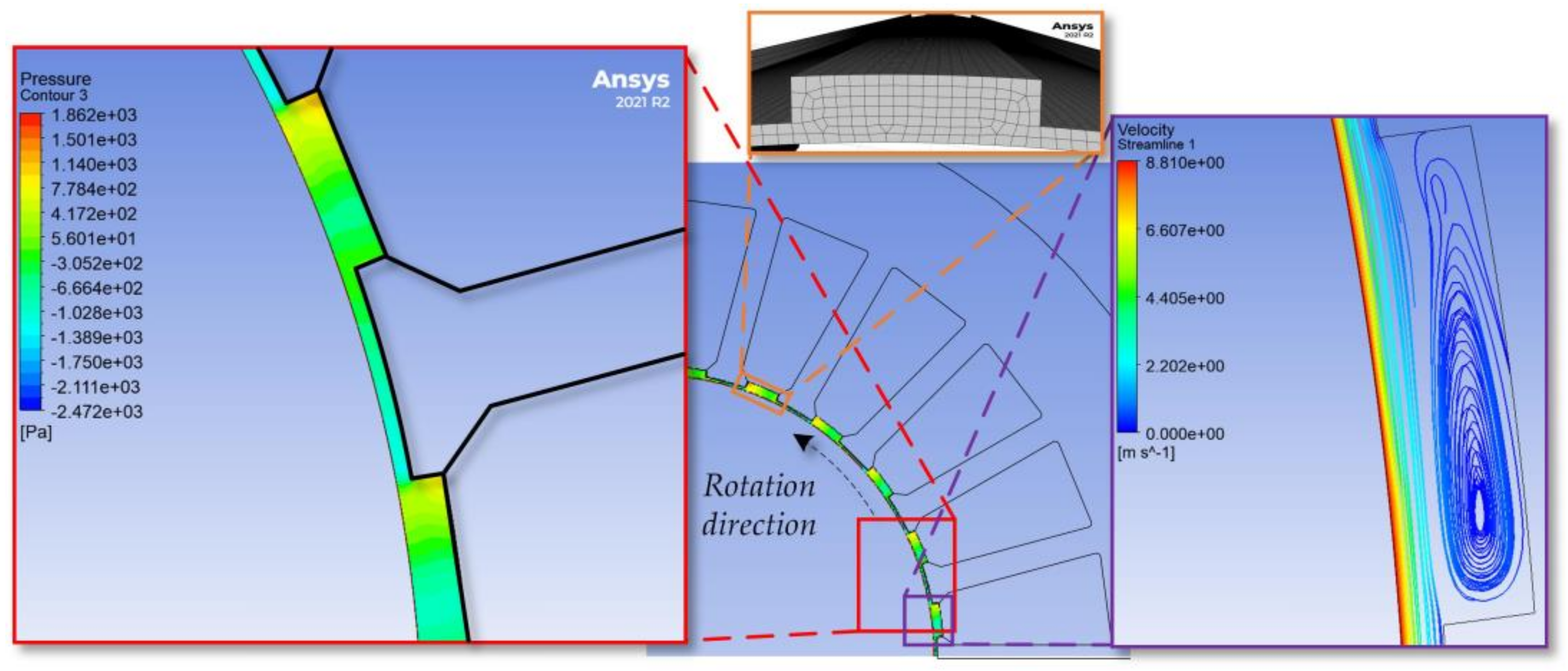
3.1. Analysis without a Wedge Inserted in Stator Slots

In this arrangement, slot wedges are absent, enabling the fluid in the air gap cavity to penetrate the windings as depicted in Figure 2. The fluid damping loss is computed with 1, where CFD analysis is utilized to determine the crucial parameters, which are dynamic pressure and drag force. These values are subsequently utilized to calculate the skin friction coefficient using 2. Notably, the stationary stator surface exhibits significant indentations, as illustrated in Figure 2.
The analysis was conducted across a range of speeds, spanning from 52.4 rad/s to 314.2 rad/s. Based on the analysis results, the damping loss ranged from 1.7 W to 384.4 W, as illustrated in Table 2. The findings clearly demonstrate that damping loss experiences exponential growth with speed. Given that the considered motor has an output power of 5.5 HP (4 kW), it is noteworthy that nearly 10% of the overall loss is attributed to fluid damping. However, it is important to note that the motor cannot be operated without a wedge to prevent physical damage to the windings and rotating components. Consequently, further analysis results are not considered for the no-wedge structure. The sole purpose of initiating the analysis with a no-wedge structure was to assess the impact of deeper surface indentations.

3.2. Analysis with Standard Wedge Inserted in Stator Slots

In this setup, standard stator slot wedges are placed into the slots to secure the windings, as illustrated in Figure 3. As seen from the figure, the indent level on the stator surface decreased. Consequently, water fluctuations within the indented areas are less pronounced compared to the case where wedges are absent, resulting in smaller damping loss.
The analysis results are summarized in Table 3. According to the analysis results that are summarized in Table 3, the recorded loss at 52.4 rad/s is 1.6 W, while the loss at 314.2 rad/s is 376.3 W. In comparison to the no-wedge structure, a slight decrease in damping loss is observed. These findings suggest that the level of indentation does not have a significant impact on damping loss. Figure 4 illustrates the pressure distribution (red window) and the fluid velocity streamline (purple window) within the air gap and in the slot indent cavity in addition to the mesh adopted (orange window) for the analysis. As the water flows across the rotor surface, some portion of it enters the slot indents and starts rotating. This behavior is related to the transitional cavity flow regimes [21] which is dependent on the geometry of the cavity and the velocity of the flow. The characterization and the measurements of the pressure and velocity dynamics in rectangular cavities can be found in the literature [21,22]. Consequently, the rotating fluid causes pressure variations on the rotor surface fluctuating between positive and negative values.

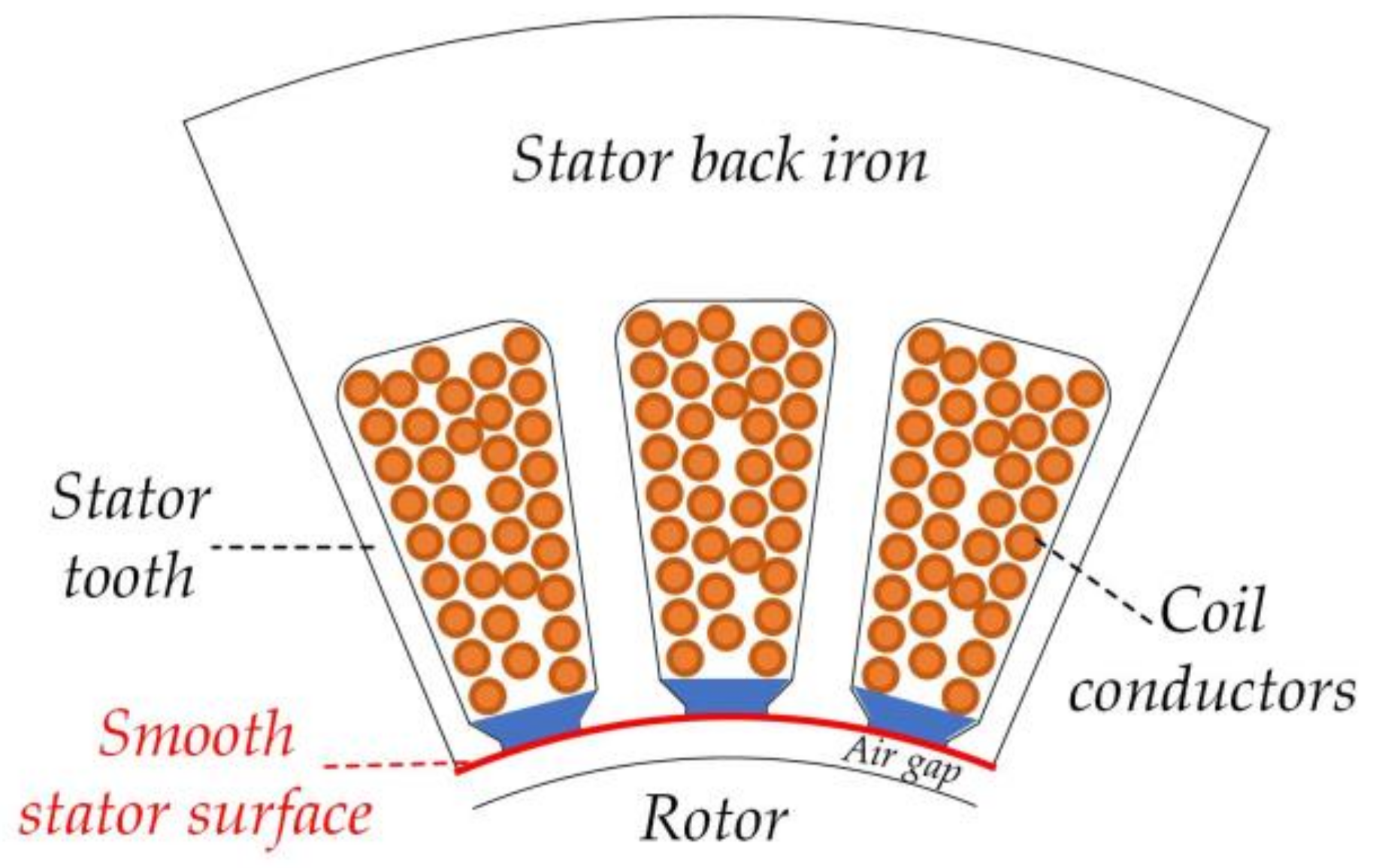
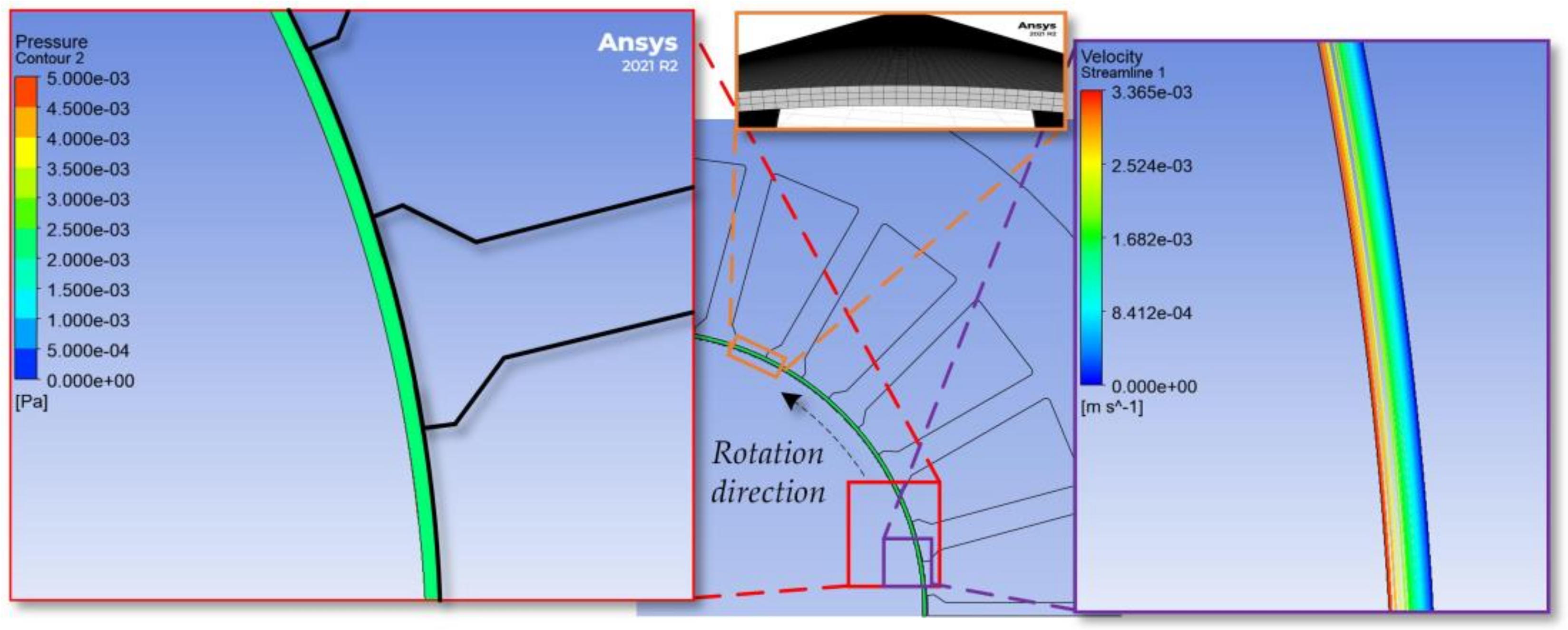
3.3. Analysis with Custom Wedge Inserted in Stator Slots

In this configuration, the objective is to entirely seal the slot openings using a custom-designed wedge structure, as depicted in Figure 5. This way, the inner surface of the stator is smoothed out and left with no indents. As a result, fluids surrounding the rotor slide across a smooth surface, leading to a dramatic reduction in damping losses.
Results for the custom no-slotting wedge structure are given in Table 4. The results indicate that the loss at 52.4 rad/s is 1.3 W, while it peaks at 314.2 rad/s to 141.6 W. Notably, this is nearly three times more efficient than the standard wedge structure at its highest operating speed. Figure 6 illustrates the pressure distribution (red window) and velocity variations (purple window) within the smooth cylindrical air gap cavity along with the mesh adopted (orange window) for the analysis. As water flows across the rotor surface, it does not enter any slot indents. Consequently, the fluid vortices are mostly eliminated, leading to a slight variation in surface pressure. This reduction in fluid vortices and pressure variations results in a significant decrease in damping loss. Examining the variations of the skin friction coefficient, Cd, variations with respect to rotor speed in Table 2, Table 3 and Table 4 reveal an almost linear trend in Table 4.
Figure 7 compares the damping loss variation between the no-wedge, standard, and custom wedge structures. It can be clearly seen that the damping loss variation is limited when there are indents on the stator surface regardless of the depth of the indents. On the other hand, the loss decreases by almost one-third of the maximum value when the stator surface is indent-free. No matter how deep the indent is, the damping loss is significantly greater than it is with the smooth surface.

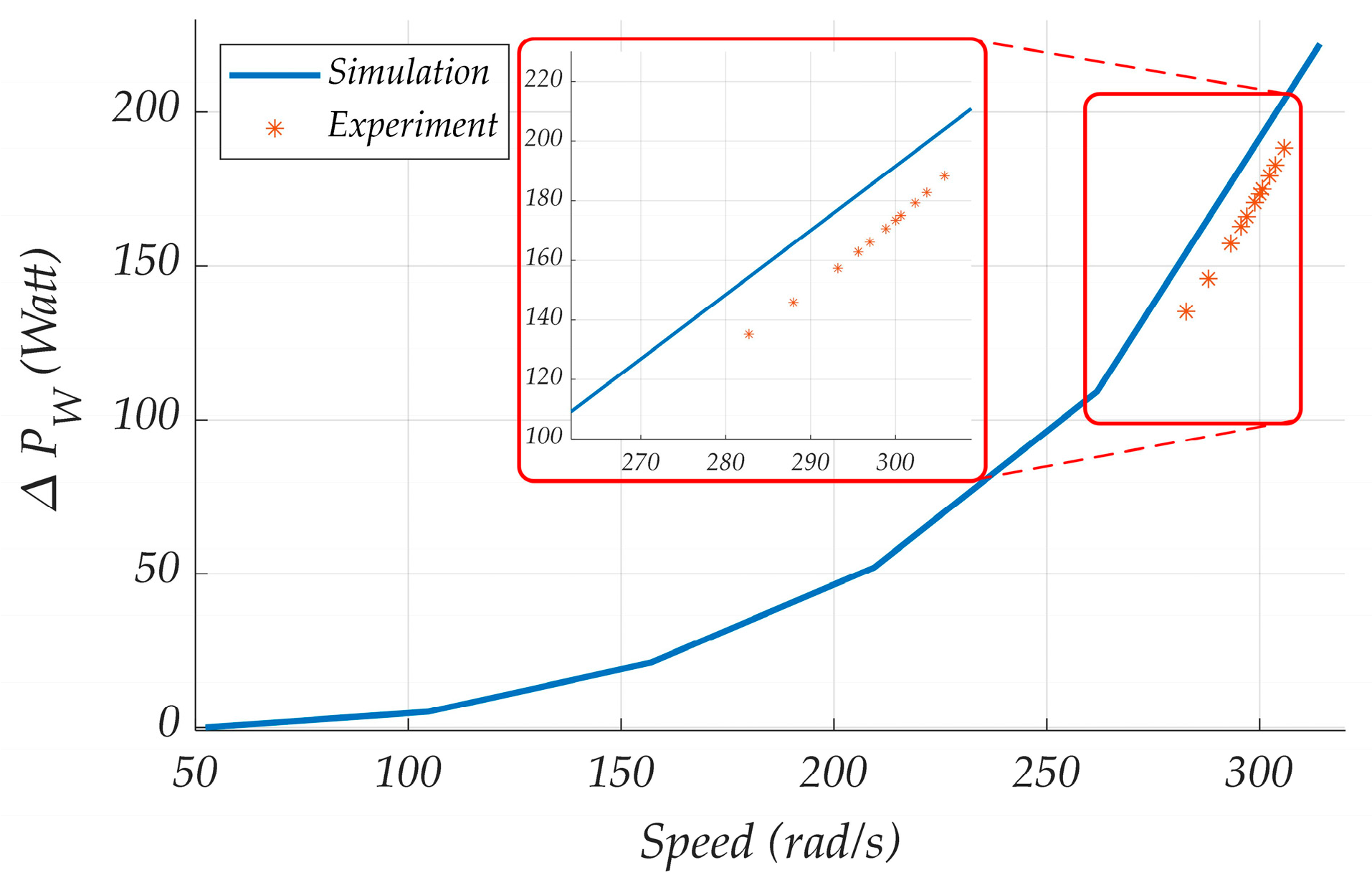
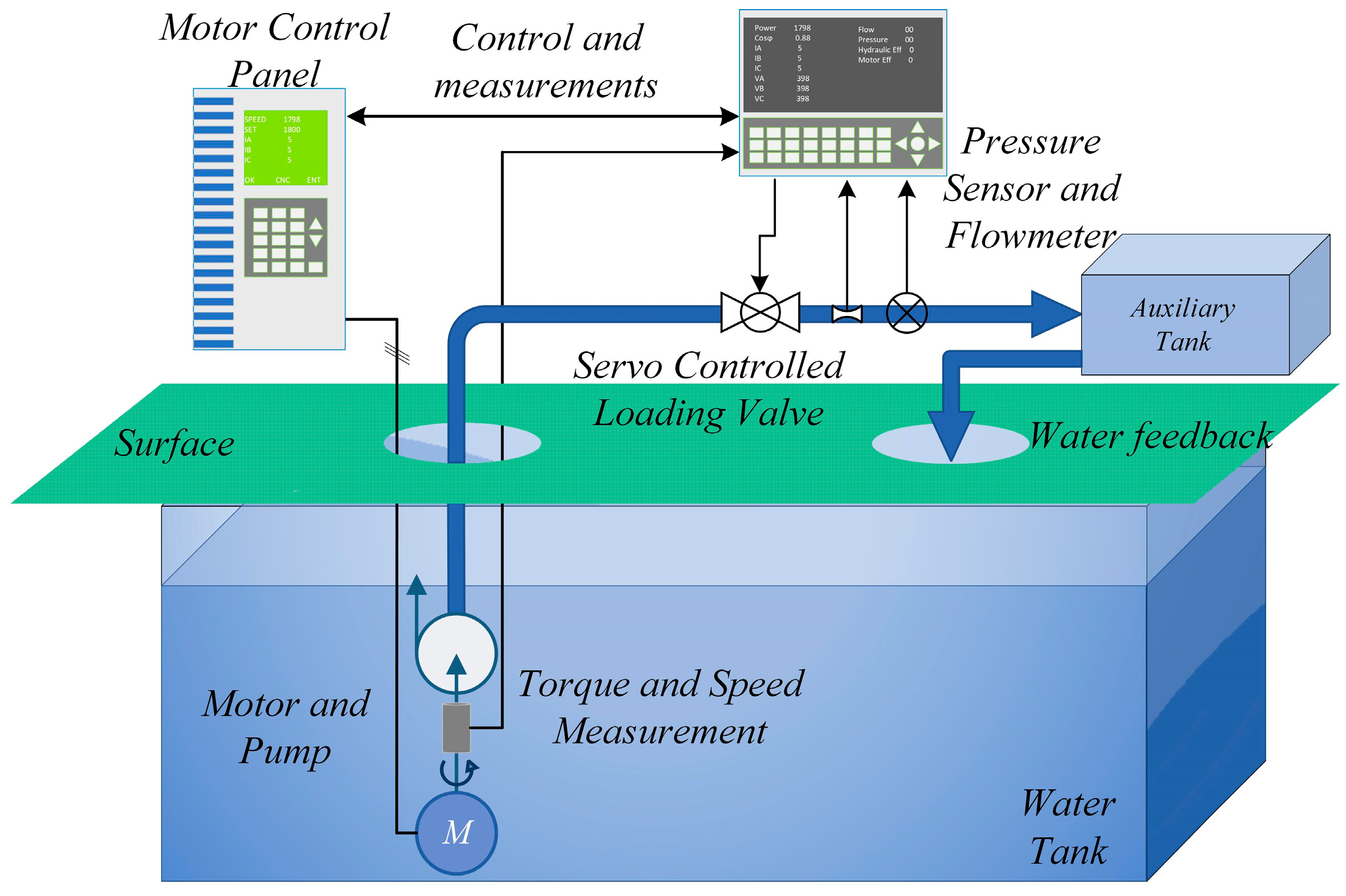
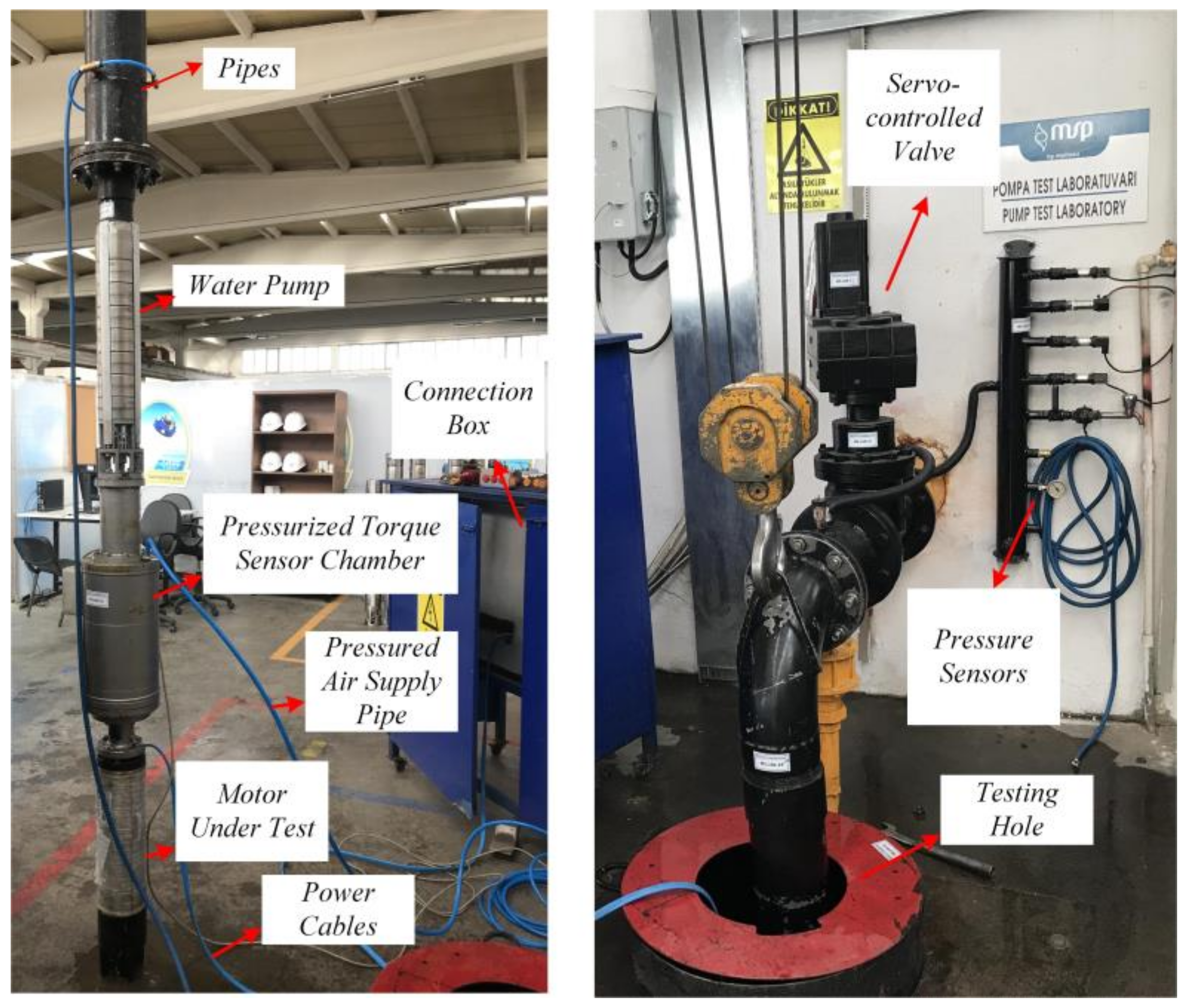
4. Experimental Verification
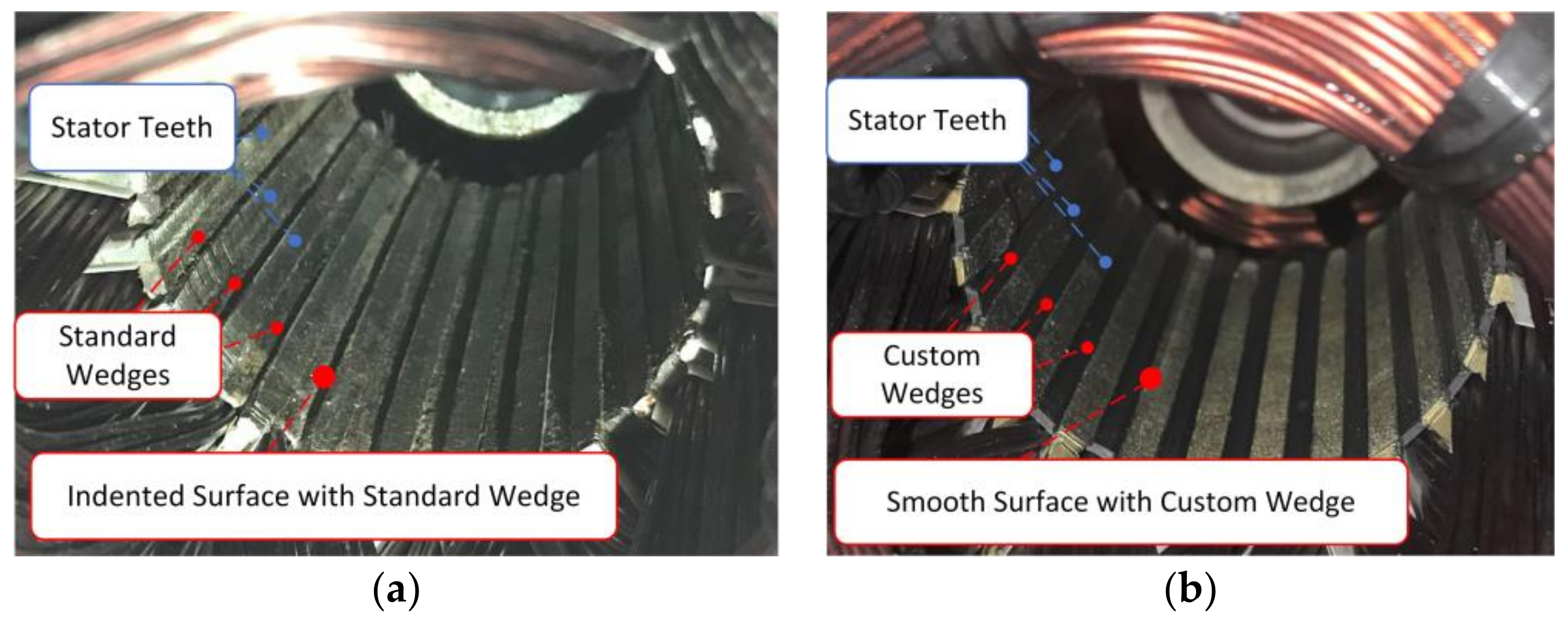
The experimental verification is performed on a motor that has regular and custom no-slotting wedge structures. First, the motor is built with the standard wedge and tested at different loading conditions. Later, the same motor is tested with the custom wedges to avoid slight performance variations due to the manufacturing. In other words, each component of the motor is kept the same but the wedges to ensure a fair and more realistic comparison. Internal views of the stators built with two wedges are shown in Figure 8. Custom-design wedges are 3D printed with a temperature-resistant thermoplastic polymer, Acrylonitrile Butadiene Styrene (ABS).

4.1. Test Setup

The tests are performed on the test system shown in Figure 9. The line voltage and current, output torque, and speed signals are fed to the test system controller for all the power and efficiency measurements.
The testing system distinguishes itself from the typical dynamometer system, where a loading motor is conventionally linked to the motor under test. Within this system, a water pump is coupled to the motor under test, both of which are placed within a water tank. A torque sensor is strategically positioned within a pressurized air chamber to avoid water intrusion into the sensor. A visual representation of the system can be observed in Figure 10. Loading is achieved through the precise regulation of water discharge using a servo-controlled valve. When the valve is completely shut, there is a complete cessation of water circulation through the pump, thereby setting the loading to its minimal level. Gradually opening the valve results in the initiation of water flow through the pump. Notably, an increase in the volume of water passing through the pump directly correlates with an augmented demand for torque to maintain the pump’s operation at a specific velocity. Consequently, the pump motor loading is variably adjusted in response to changes in the water flow rate.

4.2. Experimental Results and Discussion

With the current motor test setup adjustment, the direct measurement of the damping loss is not possible. Hence, the only observable quantity is the difference in the total losses of the motors with standard and custom wedges. Naturally, there are some limitations on the motor test platform. The first limitation is that the motor cannot reach 314.2 rad/s as it is an IM and cannot operate at synchronous speed. The second limitation is that the minimum speed cannot be 52.4 rad/s as the motor will be running through the line voltage, and loading it until the rotor speed reaches 52.4 rad/s would draw a significant amount of current and cause overheating and even burn the motor. Therefore, the speed range is adjusted so that the motor would not be damaged and can operate with line voltage by itself with minimum loading conditions. Table 5 summarizes the experimentally obtained total losses with the standard and custom wedge structures along with the total loss difference between the two measurements. During the experiments, the servo-controlled valve is precisely controlled to achieve the same mechanical shaft speed for both designs.
The total loss difference between the motors with standard and custom wedges obtained in simulations and experiments is presented in Figure 11. Obviously, the standard wedge structure reduced the total losses. Over 4% of the loss is due to the damping effect being eliminated with the custom wedge structure at the rated operating condition. The experimental results slightly deviated from the simulation results, which can be related to the measurement errors and the assumption that the stator surface is perfectly smooth with the custom wedge structure as there are some imperfections on the wedge surfaces.
In summary, analytical fluid damping loss calculations cannot accurately calculate the fluid damping losses as the fluid and air behaviors are quite distinct from each other; the density and the viscosity of the fluids differ from the air. Consequently, the determination of the fluid damping loss requires numerical analyses such as CFD. According to the performed analysis with CFD, it can be inferred that damping loss is at its lowest when the stator surface is entirely smooth, and it increases significantly even with minor surface indentations. While direct experimental measurements of damping loss may not be feasible in our test system, its influence can be observed indirectly through total loss measurements. Experiments involving standard and custom wedge structures show a significant difference in terms of the total loss, which can be attributed to the effectiveness of custom wedge designs in minimizing fluid damping loss. Based on the findings, with the standard wedges, 329 W damping loss is calculated at the rated speed, which exceeds 8% of the shaft power. Conversely, if the damping effect is disregarded and it is assumed that the fluid in the motor cavity behaves like air, the windage loss remains at just 0.69 W at the rated speed. There exists a minor distinction in the designs when the wedge is absent, which can be considered negligible. Nevertheless, crafting a custom wedge to create a smooth surface that seals the openings and eliminates all irregularities leads to a reduction in damping loss to 129 W at the rated speed, which is about 3.2% of the shaft power.

5. Conclusions

Flooded motors, which are filled with fluids and typically utilize PVC-insulated wires with a thick PVC layer, are commonly favored for applications in which cables are in contact with fluids. Consequently, the stator slot openings in these motors are wider than those found in industrial ones. Even when the standard wedges are present, a recessed surface develops on the stator’s inner surface where fluid flow irregularities lead to fluctuations in pressure on the rotor surface. Consequently, this leads to the generation of fluid damping loss. This study explores various stator inner surface structures with varying indentations to demonstrate that the machine performance is impacted by fluid damping losses significantly and should not be disregarded or simply assumed as windage losses, as is the case for air-filled motors. A series of computational fluid dynamics (CFD) analyses were conducted to assess damping losses in flooded machines using various wedge structures. The findings indicate that designs featuring even minor indents on the stator surface resulted in elevated fluid damping losses. However, the stator with a custom-designed smooth surface wedge, free of indents, reduced the damping loss from 329 to 129 W at the rated operating speed. Subsequently, two identical motors equipped with standard and custom wedges were constructed and subjected to experimental testing to confirm the findings. Given the constraints of our test system, it is not feasible to directly measure fluid damping losses. However, the impact of a smooth stator surface can be differentiated by analyzing variations in total motor losses at different speed levels. By comparing the power loss differences between motors with standard and custom wedge structures, as obtained through simulations and experiments, a strong correlation is identified. This investigation yields two significant findings:
  • Fluid damping loss represents a substantial fraction of the total losses in submerged motors and should not be disregarded in the design phase.
  • Smooth surfaces facilitate fluid flow, resulting in reduced pressure variations and a significant reduction in damping loss. Consequently, sealing all stator slot openings with custom-designed wedges emerges as a highly effective approach to achieving this goal.

Author Contributions

Conceptualization, D.T. and B.T.; methodology, D.T. and B.T.; software, D.T. and B.T.; validation, D.T. and B.T.; investigation, D.T.; resources, D.T.; data curation, D.T. and B.T.; writing—original draft preparation, D.T. and B.T.; writing—review and editing, D.T.; visualization, B.T. All authors have read and agreed to the published version of the manuscript.

Funding

This research is supported by The Scientific and Technological Research Council of Turkey (TUBITAK) under Grant number 121E413.

Data Availability Statement

Data are contained within the article.

Acknowledgments

The authors would like to thank Mutlu Su Pumps and Motors for their collaboration on this study. The authors thank the editors and reviewers for their valuable contributions.

Conflicts of Interest

The authors declare no conflict of interest. The funders had no role in the design of the study; in the collection, analyses, or interpretation of data; in the writing of the manuscript; or in the decision to publish the results.

References

  1. Stoffel, B. The Role of Pumps for Energy Consumption and Energy Saving. In Assessing the Energy Efficiency of Pumps and Pump Units; Elsevier: Amsterdam, The Netherlands, 2015; pp. 1–24. [Google Scholar] [CrossRef]
  2. Ahmed, S.; Toliyat, H.A. Coupled Field Analysis Needs in the Design of Submersible Electric Motors. In Proceedings of the 2007 IEEE Electric Ship Technologies Symposium, Arlington, VA, USA, 21–23 May 2007. [Google Scholar]
  3. Borkowski, D.; Węgiel, M.; Ocłoń, P.; Węgiel, T. CFD Model and Experimental Verification of Water Turbine Integrated with Electrical Generator. Energy 2019, 185, 875–883. [Google Scholar] [CrossRef]
  4. Sashidhar, S.; Fernandes, B.G. A Novel Ferrite SMDS Spoke-Type BLDC Motor for PV Bore-Well Submersible Water Pumps. IEEE Trans. Ind. Electron. 2017, 64, 104–114. [Google Scholar] [CrossRef]
  5. Villani, M.; Santececca, M.; Parasiliti, F. High-Efficiency Line-Start Synchronous Reluctance Motor for Fan and Pump Applications. In Proceedings of the 2018 23rd International Conference on Electrical Machines, ICEM 2018, Alexandroupoli, Greece, 3–6 September 2018; pp. 2178–2184. [Google Scholar] [CrossRef]
  6. Li, J.; Song, J.; Cho, Y. High Performance Line Start Permanent Magnet Synchronous Motor for Pumping System. In Proceedings of the 2010 IEEE International Symposium on Industrial Electronics, Bari, Italy, 4–7 July 2010; pp. 1308–1313. [Google Scholar] [CrossRef]
  7. Baka, S.; Sashidhar, S.; Fernandes, B.G. Design of an Energy Efficient Line-Start Two-Pole Ferrite Assisted Synchronous Reluctance Motor for Water Pumps. IEEE Trans. Energy Convers. 2021, 36, 961–970. [Google Scholar] [CrossRef]
  8. Sorgdrager, A.J.; Wang, R. Design and Optimisation of a Line-Start Synchronous Reluctance Motor. In Proceedings of the Southern African Universities Power Engineering Conference, Johannesburg, South Africa, 26–28 January 2016. [Google Scholar] [CrossRef]
  9. Al-Timimy, A.; Giangrande, P.; Degano, M.; Xu, Z.; Galea, M.; Gerada, C.; Lo Calzo, G.; Zhang, H.; Xia, L. Design and Losses Analysis of a High Power Density Machine for Flooded Pump Applications. IEEE Trans. Ind. Appl. 2018, 54, 3260–3270. [Google Scholar] [CrossRef]
  10. Liu, J.; Yan, L.; He, X.; Zhou, Y.; Yu, Z. Analysis of Oil Viscous Drag Loss of Deep-Sea Motor Based on CFD Method. In Proceedings of the ICIEA 2022—17th IEEE Conference on Industrial Electronics and Applications, Chengdu, China, 16–19 December 2022; pp. 1289–1293. [Google Scholar] [CrossRef]
  11. Guo, H.; Lv, Z.; Wu, Z.; Wei, B. Multi-Physics Design of a Novel Turbine Permanent Magnet Generator Used for Downhole High-Pressure High-Temperature Environment. IET Electr. Power Appl. 2013, 7, 214–222. [Google Scholar] [CrossRef]
  12. Andereckt, I.D.; Lius, S.S.; Swinney, H.L. Flow Regimes in a Circular Couette System with Independently Rotating Cylinders. J. Fluid Mech. 1986, 164, 155–183. [Google Scholar] [CrossRef]
  13. Xianghui, L.; Dianrong, G. Flow Field Analysis and Computation of the Fixed Damping Orifice of the Servo Valve. In Proceedings of the 2011 International Conference on Fluid Power and Mechatronics, Beijing, China, 17–20 August 2011; pp. 10–15. [Google Scholar] [CrossRef]
  14. Zou, J.; Qi, W.; Xu, Y.; Xu, F.; Li, Y.; Li, J. Design of Deep Sea Oil-Filled Brushless DC Motors Considering the High Pressure Effect. IEEE Trans. Magn. 2012, 48, 4220–4223. [Google Scholar] [CrossRef]
  15. Wonham, J. Effect of Pressure on the Viscosity of Water. Nature 1967, 215, 1053–1054. [Google Scholar] [CrossRef]
  16. Tekgun, D.; Alan, I. A New Oval Shaft, High Performance, 2 Pole Line Start Synchronous Reluctance Machine for Submersible Pump Applications. Int. J. Appl. Electromagn. Mech. 2022, 70, 73–93. [Google Scholar] [CrossRef]
  17. Tekgun, D.; Muhsin Cosdu, M.; Tekgun, B.; Alan, I. Effect of the Stator Slot Indents on Fluid Damping Loss in Submersible Pump Applications; Effect of the Stator Slot Indents on Fluid Damping Loss in Submersible Pump Applications. In Proceedings of the 2022 4th Global Power, Energy and Communication Conference (GPECOM), Nevsehir, Turkey, 14–17 June 2022. [Google Scholar] [CrossRef]
  18. Sarlioglu, B. Understanding Electric Motors and Loss Mechanisms. Available online: https://irc.wisc.edu/export.php?ID=421 (accessed on 31 October 2023).
  19. Sadr, S.; Abdelli, A.; Ben-NachouaneIntuitive, A.; Friedrich, G.; Vivier, S. Comprehension and Estimation of Windage Losses in Rotor Slotted Air Gaps of Electrical Machines Using CFD-LES Methods. In Proceedings of the 2019 IEEE Energy Conversion Congress and Exposition (ECCE), Baltimore, MD, USA, 29 September–3 October 2019; pp. 6078–6083. [Google Scholar] [CrossRef]
  20. Vrancik, J.E. Prediction of Windage Loss in Alternators; NASA: Cleveland, OH, USA, 1967.
  21. Ng, Y.T. Characterising Low-Speed, Transitional Cavity Flow. Aeronaut. J. 2012, 116, 1185–1199. [Google Scholar] [CrossRef]
  22. Ukeiley, L.; Murray, N. Velocity and Surface Pressure Measurements in an Open Cavity. Exp. Fluids 2005, 38, 656–671. [Google Scholar] [CrossRef]
Figure 1. Liquid circulates within the air gap cavity.
Machines 11 01088 g001
Figure 2. The stator surface features indentations, without inserting any wedges into the slots.
Machines 11 01088 g002
Figure 3. The stator surface features indentations where standard wedges are present.
Machines 11 01088 g003
Figure 4. Pressure (red window) and fluid velocity variation (purple window) throughout the air gap surface with standard wedges at 314.2 rad/s speed and adopted mesh for the analysis (orange window).
Machines 11 01088 g004
Figure 5. Indent-free surface with proposed wedges.
Machines 11 01088 g005
Figure 6. Pressure (red window) and fluid velocity variation (purple window) throughout the air gap surface with smooth stator surface and adopted mesh for the analysis (orange window).
Machines 11 01088 g006
Figure 7. Fluid damping loss comparison with different wedge structures.
Machines 11 01088 g007
Figure 8. Internal view of the stators built with (a) standard, and (b) custom-made wedges.
Machines 11 01088 g008
Figure 9. Downhole pump motor test system.
Machines 11 01088 g009
Figure 10. Motor under test, torque sensor, pump assembly, servo-controlled valve, pressure sensor, flowmeter, and testing hole.
Machines 11 01088 g010
Figure 11. The total power loss differences between the motors with standard and custom wedges obtained in simulations and experiments.
Machines 11 01088 g011
Table 1. Motor Parameters.
ParameterValue
Rated Power (HP/kW)5.5/4
Rated Voltage (V)380
Rated Current (A)9.8
Number of Phases3
Number of Poles2
Rated Motor Speed (rad/s)298.45
Number of Stator Slots24
Rotor Radius (mm)34.15
Stator Radius (mm)78
Air Gap Length (mm)0.6
Axial Motor Length (mm)154
Table 2. Analysis results of the geometry without a wedge structure.
Speed (rad/s)CdPw (W)
52.40.01771.7
104.70.019714.8
157.10.020351.3
209.40.0195116.9
261.80.0196229.5
314.20.0190384.4
Table 3. Results with the standard wedges.
Speed (rad/s)CdPw (W)
52.40.01691.6
104.70.018313.7
157.10.019850.1
209.40.0195116.9
261.80.0187218.9
314.20.0186376.3
Table 4. Analysis Results with the Custom Wedges.
Speed (rad/s)CdPw (W)
52.40.01351.3
104.70.01188.8
157.10.010125.5
209.40.009255.1
261.80.0086100.7
314.20.0070141.6
Table 5. Experimental Results with Standard and Custom Wedge Structures.
Speed
(rad/s)
Total Loss with
Standard Wedge (W)
Total Loss with
Custom Wedge (W)
Total Loss
Difference (W)
282.735123377135
288.028932747146
293.222572100157
295.819701807163
297.418121646166
298.516011430171
299.514781305173
300.514141239175
302.612501071179
303.71127944183
305.8962774188
Disclaimer/Publisher’s Note: The statements, opinions and data contained in all publications are solely those of the individual author(s) and contributor(s) and not of MDPI and/or the editor(s). MDPI and/or the editor(s) disclaim responsibility for any injury to people or property resulting from any ideas, methods, instructions or products referred to in the content.

