Article

Orientation-Dependent Mechanical Behavior of 3D Printed Polylactic Acid Parts: An Experimental–Numerical Study

1
Department of Mechanical, Industrial and Manufacturing Engineering, University of Toledo, Toledo, OH 43606, USA
2
Department of Mechanical, Industrial and Aerospace Engineering, Concordia University, Montreal, QC H3G 1M8, Canada
3
Euromed Polytechnic School, Euromed Research Center, Euromed University of Fes, Fès 30 000, Morocco
4
Léonard de Vinci Pôle Universitaire, Research Center, La Défense, 92 916 Paris, France
5
Arts et Métiers Institute of Technology, CNAM, LIFSE, HESAM University, F-75013 Paris, France
6
Arts et Métiers Institute of Technology, CNRS, CNAM, PIMM, HESAM University, F-75013 Paris, France
*
Author to whom correspondence should be addressed.
Machines 2023, 11(12), 1086; https://doi.org/10.3390/machines11121086
Submission received: 19 November 2023 / Revised: 6 December 2023 / Accepted: 12 December 2023 / Published: 13 December 2023
(This article belongs to the Special Issue Advance in Additive Manufacturing)

Abstract

:
In Additive Manufacturing, wherein the construction of parts directly from 3D models is facilitated, a meticulous focus on enhancing the mechanical characteristics of these components becomes imperative. This study delves into the nuanced impact of the orientation of deposited layers on the mechanical properties of 3D printed Polylactic Acid (PLA) parts. Experimental testing, coupled with predictive modeling using Tsai–Hill and Tsai–Wu criteria, forms the crux of our investigation. The predicted ultimate strength from both criteria exhibits commendable agreement with the 3D printed specimens across a spectrum of orientation angles. Concurrently, Finite Element Simulations are meticulously executed to forecast mechanical behavior, taking into account the observed elasticity and plasticity in various orientations. Our observations reveal a significant augmentation in Young’s modulus and ductility/elongation—40% and 70%, respectively—when transitioning from θ = 0° to θ = 90°. Furthermore, the ultimate strength experiences a notable increase, leading to varied failure modes contingent upon θ. These findings underscore the pivotal role played by the orientation of printed layers in shaping the anisotropic behavior of 3D printed PLA parts, thereby integrating key process variables for optimization objectives. This study contributes valuable insights for professionals in the engineering, design, and manufacturing domains who seek to harness the advantages of 3D printing technology while ensuring that the mechanical integrity of 3D printed parts aligns with their functional requisites. It emphasizes the critical consideration of orientation as a design parameter in the pursuit of optimization objectives.

1. Introduction

Producing complex geometries for different applications (aerospace, automotive, biomedical, etc.) using Additive Manufacturing (AM) has progressively revolutionized manufacturing in the context of Industry 4.0 in recent decades [1,2]. AM comprises a group of promising techniques aimed at the construction of complex geometries, and it refers to the process of joining materials to build a 3D object from a 3D model. Various 3D printing techniques, each with distinct methodologies, materials, and applications, contribute to the versatility of Additive Manufacturing. Fused Filament Fabrication (FFF) or Fused Deposition Modeling (FDM) excels in rapid prototyping and functional parts by extruding thermoplastic filaments layer by layer. Stereolithography (SLA) stands out for its high-detail prototypes and intricate models, using a laser to solidify liquid resin. Selective Laser Sintering (SLS) achieves functional prototypes through the laser sintering of powdered materials, offering a wide range of thermoplastics. Digital Light Processing (DLP) is akin to SLA but cures entire layers simultaneously, making it suitable for applications like dental work and jewelry. Binder Jetting provides versatility with materials like metals and ceramics, depositing a liquid binder onto a powder bed. PolyJet (Stratasys) Printing combines inkjet-like technology with UV-cured liquid photopolymers, which are ideal for high-detail multi-material prints. Metal 3D printing techniques such as Direct Metal Laser Sintering (DMLS) and Electron Beam Melting (EBM) leverage lasers or electron beams to sinter or melt metal powder, which is essential for aerospace components and medical implants. Bioprinting, focused on creating biological structures with living cells, finds applications in tissue engineering and regenerative medicine. A comprehensive comparison among these techniques involves considerations such as material selection, printing speed, resolution, cost, and suitability for specific applications, guiding users to choose the most fitting method for their unique requirements [3].
Fused Filament Fabrication (FFF), also known as 3D printing, is one of the most promising AM techniques [4]. In this process, the main mechanism is based on the extrusion of thermoplastic materials, either polymers or composites, while there is movement of successive X-Y planes along the Z direction to construct a 3D object layer by layer [5]. Consequently, it is inevitable to consider these 3D printed structures as transversely isotropic materials, and thus, there are the same mechanical properties in the mentioned planes. However, the mechanical properties in the Z direction (perpendicular to the deposited layers) are not the same as those so-called transverse planes. Yet, there are several parameters in FFF (e.g., layer thickness, liquefier temperature, platform temperature, and print speed) that are required to be thoroughly optimized to obtain high-quality parts.
In the literature, numerous works have addressed thermal modeling and temperature measurements concerning the temperature evolution in FFF [6,7]. Finite Element Simulations have been employed to model the cooling stages of FFF during material deposition under various input conditions [8,9,10]. A 2D transient heat transfer analysis has been developed, aimed at investigating the solidification of a filament in a vertical stack, representing a lower cooling rate that promotes bonding [11]. Heat transfer through successive layers has also been numerically simulated to demonstrate the impact of print speed on the bonding between adjacent filaments [12]. Significantly, extensive numerical research has been conducted to comprehend the heat conduction from the liquefier and platform while the polymer passes through the liquefier and is subsequently deposited on the platform [13,14].
The orientation of filament layers exerts a profound influence on the mechanical properties of the final printed objects. This effect is a critical consideration for engineers, designers, and manufacturers seeking to create parts with specific strength, flexibility, and durability characteristics. One of the key aspects affected by filament orientation is layer bonding strength [15,16]. How well adjacent layers adhere to each other significantly impacts the overall structural integrity of the printed object. Proper layer orientation can enhance interlayer adhesion, resulting in a stronger and more reliable component. Conversely, improper orientation may lead to weak layer bonding and compromise the mechanical strength of the object [17]. Anisotropy is another significant outcome of filament orientation. In particular, 3D printed objects are often anisotropic, meaning their mechanical properties differ in various directions. Typically, parts exhibit greater strength along the vertical axis (the z-direction) due to continuous layer stacking, while their strength may be comparatively lower along the horizontal axes (the x- and y-directions). Designers must account for this anisotropy when engineering parts to meet specific performance requirements [18].
Shear and tensile strength are also strongly influenced by filament orientation. Objects with layers oriented parallel to the expected direction of force application tend to exhibit greater strength in that particular direction. For instance, parts subjected to tensile forces benefit from layers oriented to align with the anticipated pull, resulting in enhanced tensile strength. Likewise, layers oriented to withstand shear forces enhance the object’s resistance to shearing stresses [18].
The flexibility and impact resistance of 3D printed objects are likewise subjected to filament orientation. Layers oriented to allow more freedom of movement between them create more flexible parts, which are suitable for applications requiring a certain degree of elasticity. Conversely, layers oriented for tight interlocking can make the part more rigid and impact-resistant, which is ideal for scenarios where strength and durability are paramount. Casavola et al. [19] described the mechanical behavior of FFF-produced parts through the application of classical laminate theory. They experimentally determined essential elastic constants, including E1, E2, U12, and G12, which are critical for understanding the material’s properties. Somireddy et al. [20] introduced a constitutive modeling approach for FFF-printed components using a numerical homogenization technique. Their work revealed that the material behavior within various sections of the structure was not uniform and was influenced by factors like build orientation and part thickness. Domingo-Espin et al. [21] characterized FFF-printed parts as anisotropic solids and derived nine elastic constants for use in simulations. They further designed and produced a basic part in multiple orientations for both physical testing and simulation purposes. Abadi et al. [22] conducted an assessment of the elastic properties of 3D printed fiber-reinforced polymers. Their parametric study findings demonstrated that the quantity of fiber reinforcements and their arrangement significantly affected the structural performance of the 3D printed composite parts made from fiber-reinforced polymers.
The mentioned studies highlight several key studies related to the mechanical behavior and impact of filament orientation of 3D printed parts, offering valuable insights into different aspects of this field. Collectively, these studies underscore the importance of understanding the complex relationship between material properties, print orientation, and structural performance in 3D printed parts. They provide valuable data and methodologies for optimizing the mechanical behavior of printed components, which is essential for various engineering and manufacturing applications. Nonetheless, a significant issue is presented in prior research. Previous studies have primarily conducted qualitative assessments of strength and Young’s modulus for AM materials, relying on some empirical models. However, a precise quantitative assessment of how the printing angle and layer thickness affect the strength and Young’s modulus of AM materials remains a gap in our understanding. To advance the progress of 3D printing technology and the effective utilization of polymeric and/or polymer-based composite materials in 3D printing, there is an urgent need for the development of quantitative theoretical models that can provide precise insight into the mechanical properties of this material. A more comprehensive exploration of the material’s mechanical characteristics is also imperative.
In addition to these mechanical properties, filament orientation affects the practical aspects of 3D printing, such as print time and material usage. By optimizing the orientation, it is possible to reduce printing time and minimize material waste, making the process more efficient and cost-effective. Filament orientation is a pivotal variable in 3D printing, with direct and profound implications for the mechanical properties of the end product. The careful consideration of layer orientation is essential for achieving the desired functional and structural characteristics in 3D printed objects. This allows for tailoring the printed parts to meet specific design requirements, from strength and rigidity to flexibility and impact resistance.
In this study, the effect of filament orientation was analyzed under a quasi-static loading test. The ultimate strength of the 3D printed specimens was predicted numerically to be compared with the experimental test under various orientation angles. Finally, FEM was implemented to identify the tensile behavior of the specimens in different directions to verify the prediction from the models and obtained experimental results.

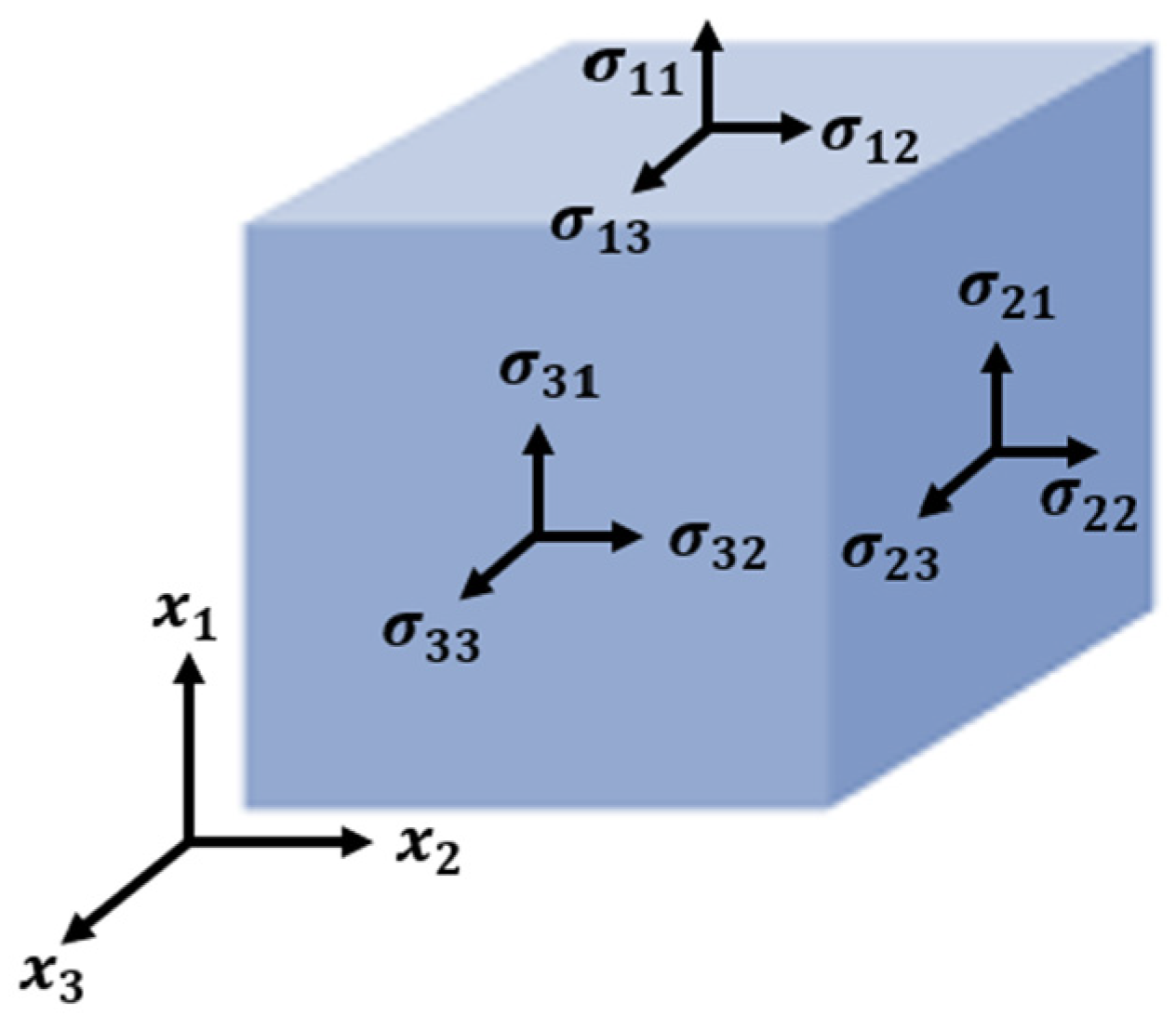
2. Theoretical Modeling

In the early phases of research aimed at exploring the connection between the parameters used in 3D printing and the resulting mechanical properties of printed objects, the primary focus was on establishing straightforward and direct relationships. Specifically, scientists and engineers concentrated on factors like how changes in stiffness were influenced by the orientation of the printed layers (referred to as raster orientation) and how the yield properties of a material varied depending on the orientation in which it was built. This initial research was somewhat limited in scope, as it addressed specific, isolated aspects of the printing process.
However, in more recent times, the direction of this research has evolved significantly. Rather than solely examining these isolated relationships, there has been a notable shift toward developing more comprehensive and holistic models that can provide a more in-depth and complete understanding of a material’s behavior. This shift reflects the recognition that material behavior is a complex and multifaceted phenomenon. A broader perspective on material behavior is crucial for a number of reasons. Firstly, it enables us to gain a deeper insight into the limits of a material in all spatial directions. In other words, it allows us to understand how a material will perform when subjected to various types of stress from different directions, not just the traditional unidirectional stress. This is particularly important when dealing with materials used in complex engineering applications where forces act in multiple directions simultaneously.
Furthermore, these comprehensive models are essential for simulating and testing materials under various loading conditions, which can include scenarios with multiple forces acting simultaneously. Such simulations are critical in industries like aerospace, automotive, and civil engineering, where materials are subjected to diverse and complex loads. Accurately predicting how a material will respond under these conditions is essential for design, safety, and performance. Additionally, understanding a material’s yield behavior, which refers to the point at which it undergoes plastic deformation or permanent changes in shape under stress, is of paramount importance for creating accurate material models used in Finite Element Analysis (FEA). FEA is a numerical simulation technique widely employed in engineering and science to analyze the behavior of structures and materials under various conditions. A precise understanding of yield behavior is fundamental for ensuring that FEA models accurately represent real-world material responses, ultimately leading to safer and more efficient designs in a wide range of applications.
In the context of this paper, our focus will be on predicting the yield point of FFF-3D printed materials in full three-dimensional (3D) orientations, taking into account the aspect of solidity. Such predictions can greatly assist design engineers in optimizing the printing process to create load-bearing components with a maximized strength-to-weight ratio. Equation (1) illustrates the stress tensor, which describes the general state of stress acting on a material:
σ = σ x x τ x y τ x z τ y x σ y y τ y z τ z x τ z y σ z z
The challenge that arises in engineering and materials science is the determination of the stress level at which failure will occur in a material, especially when multiple types of stresses are acting simultaneously. For many applications, the yield stress of a material is a critical design consideration, especially in components designed to bear loads. Engineers often express safety factors as a fraction of the material’s yield stress because exceeding the yield stress results in permanent deformation, making it challenging to predict the stress behavior due to the changing geometry of the deforming material. The complexity is further amplified when dealing with materials that are orthotropic or anisotropic, as is the case with many AM materials produced using FFF techniques. These materials exhibit unique properties due to their fibrous and layered structure. In orthotropic materials, mechanical properties vary depending on the direction of the load, while anisotropic materials exhibit different mechanical properties in different directions. These variations make predicting material behavior and failure points even more challenging.
One approach that has been explored to address this challenge and predict the yield strength of an AM material is to use the Hill criterion. The Hill criterion, developed in 1948 [23], was initially based on studies involving cold-rolled steels. This criterion is represented mathematically in Equation (2), as follows:
F σ x x σ y y 2 + G σ y y σ z z 2 + H σ z z σ x x 2 + 2 L τ x y 2 + 2 M τ y z 2 + 2 N τ x z 2 = 1
In this context, F, G, H, L, M, and N denote the distinct material coefficients responsible for characterizing anisotropy. These coefficients are derived from the yield stresses, as follows:
F + G = 1 σ y i e l d ,   z z 2
F + H = 1 σ y i e l d ,   y y 2
G + H = 1 σ y i e l d ,   x x 2  
2 L = 1 σ y i e l d ,   y z 2
2 M = 1 σ y i e l d ,   z x 2
2 N = 1 σ y i e l d ,   x y 2
By utilizing the Hill criterion and other modeling techniques, researchers and engineers aim to gain a better understanding of how materials with complex structures, such as those produced through AM processes, behave under various loads and conditions. This understanding is crucial for designing components and structures that are both safe and efficient in the face of the complex mechanical challenges they may encounter. The Hill criterion possesses significant advantages that make it a valuable tool for analyzing material behavior in various contexts. There are two primary aspects in which it excels. First, it has the capability to handle the complete 3D state of stress, which means it can account for stress from all directions, providing a more comprehensive understanding of the material’s response to various loads. Second, the Hill criterion simplifies the complex problem of material failure prediction into a single parameter, making it more straightforward and practical compared to some other models.
This single-parameter feature is particularly advantageous when contrasted with other models that might be limited to handling only in-plane stresses or involve multiple checks for failure, such as the maximum stress or maximum strain theories. The effectiveness of the Hill failure criterion in predicting the strength of 3D printed materials has been demonstrated in various studies [24,25]. These studies showcased the Hill criterion’s ability to accurately forecast the failure of 3D printed materials under different orientations, and, notably, in the case of the Rodrigues study, even under bending loads. It is worth noting that these studies typically employed a cross-weave (45°/−45°) raster arrangement to achieve in-plane isotropy, which is a common approach, but not the only one, for a 3D printed component. Additionally, the Hill criterion was initially developed for ductile, anisotropic metals. However, 3D printed materials exhibit characteristics more akin to fibrous composites rather than anisotropic solids, as observed from their failure modes. Recognizing this difference, Tsai, in 1965, sought to adapt the Hill criterion to work with composite materials by introducing a new set of principal directions.
Tsai’s adaptation involved defining these axes based on the local fiber directions, deviating from the traditional x, y, and z Cartesian coordinate system. In Tsai’s system, 1 represents the longitudinal direction along the fiber, 2 represents the transverse fiber-to-fiber direction, and 3 represents the vertical direction from layer to layer. Shear planes are then determined based on these new axes, with 4 representing the 2–3 plane, 5 representing the 1–3 plane, and 6 representing the 1–2 plane [26]. This adaptation allowed the Hill criterion to be more effectively applied to the specific characteristics of fibrous composite materials, enabling a more accurate prediction of their behavior under different loading conditions (Figure 1).
Tsai–Hill (TH) and Tsai–Wu (TW) represent two appropriate criteria, as shown in Equations (9) and (10), while:
T H = σ 11 2 X 2 + σ 22 2 Y 2 + σ 33 2 Z 2 + τ 23 2 Q 2 + τ 13 2 R 2 + τ 12 2 S 2 σ 11 σ 22 1 X 2 + 1 Y 2 1 Z 2 σ 11 σ 33 1 X 2 1 Y 2 + 1 Z 2 σ 22 σ 33 1 X 2 + 1 Y 2 + 1 Z 2
where X, Y, and Z are normal strengths in in-axis directions as well as Q, R, and S, which are the shear strengths and:
T W = F 1 σ 11 + F 2 σ 22 + F 3 σ 33 + F 11 σ 11 2 + F 22 σ 22 2 + F 33 σ 33 2 + F 44 σ 23 2 + F 55 σ 13 2 + F 66 σ 12 2 + 2 F 12 σ 11 σ 22 + 2 F 13 σ 11 σ 33 + 2 F 23 σ 22 σ 33
where F n n the are functions of strengths as follow:
F 1 = 1 X T + 1 X C
F 2 = 1 Y T + 1 Y C
F 3 = 1 Z T + 1 Z C
F 11 = 1 X T X C
F 22 = 1 Y T Y C
F 33 = 1 Z T Z C
F 44 = 1 Q 2
F 55 = 1 R 2
F 66 = 1 S 2
It is worth noting that, unlike the Tsai–Hill criterion, the Tsai–Wu criterion explicitly incorporates tensile strengths and compressive strengths. F12, F13, and F23 represent additional parameters, and various methods exist to determine them. For both criteria, when the right side of the equation reaches 1, failure occurs. As the thickness of the specimens is relatively small compared to other dimensions, the plane stress assumption can be applied. Consequently, the formulas under failure conditions can be expressed as follows:
σ 11 2 X 2 + σ 22 2 Y 2 + τ 12 2 S 2 σ 11 σ 22 1 X 2 + 1 Y 2 1 Z 2 = 1
F 1 σ 11 + F 2 σ 22 + F 11 σ 11 2 + F 22 σ 22 2 + F 66 σ 12 2 + 2 F 12 σ 11 σ 22 = 1
Since our orthotropic material is transversely isotropic, Y = Z. We also assume that the difference between the magnitude of compressive strengths and tensile strengths is negligible. Consequently, F1 = F2 = 0.
σ 11 2 X 2 + σ 22 2 Y 2 + τ 12 2 S 2 σ 11 σ 22 X 2 = 1
F 11 σ 11 2 + F 22 σ 22 2 + F 66 σ 12 2 + 2 F 12 σ 11 σ 22 = 1
The relations between in-axis and off-axis coordinate systems when only tensile stress along the specimen applies are as follow:
σ 1 = σ x · c o s 2 θ
σ 2 = σ x · s i n 2 θ
τ 12 = σ x · s i n θ · c o s θ
Here, the expression of σ x , which represents the strength along the specimen, is:
σ x = 1 c o s 4 ( θ ) X 2 + s i n 4 ( θ ) Y 2 + 1 S 2 1 X 2 · ( s i n 2 θ · c o s 2 ( θ ) ) ( Tsai Hill )
σ x = 1 F 11 c o s 4 ( θ ) + F 22 s i n 4 ( θ ) + F 66 + 2 F 12 · ( s i n 2 θ · c o s 2 ( θ ) ) ( Tsai Wu )
By comparing two equations, we can conclude that only one term distinguishes two methods for the specimens in this paper. Using 1 x 2 for Tsai–Hill criterion and 2 F 12 for Tsai–Wu criterion, two methods can be used in order to calculate F 12 . The easier one is to use the following equation (Tsai–Wu1):
F 12 = 1 2 X T X C Y T Y C = 1 2 F 11 , F 22
Moreover, using experimental data when failure occurs in a specimen when 0 < θ < 90 can reach F12 (Tsai–Wu2):
F 12 = 1 2 1 σ x 2 · c o s 2 θ · s i n 2 θ F 11 · c o s 2 θ s i n 2 θ + F 22 · s i n 2 θ c o s 2 θ + F 66
In conclusion, the efficacy of the Hill model in predicting the material properties of FFF-printed objects has been unequivocally demonstrated through systematic experimentation and verification using numerical methods. This approach strategically highlights the utility of these models for accurately predicting the ultimate strength of applied materials. Importantly, this method obviates the need for extensive and costly experimental manipulations, as it efficiently incorporates both Hill criteria to express ultimate strength. Notably, the presented approach is not only instrumental for predicting ultimate strength, but it is also applicable for forecasting the yield strength of the material. It holds promise for integration into optimization platforms, facilitating a comprehensive exploration of the parameters inherent in the manufacturing process.

3. Material and Experimental Methodology

3.1. PLA Filament

A commercial PLA filament with a 1.75 mm (±0.01 mm) diameter, produced by the manufacturer Fillamentum®, was used for specimen construction. Table 1 displays certain physico-chemical characteristics of this filament.

3.2. D Printer Device

The printed parts were manufactured using a desktop 3D printer (Flashforge Creator 3), including a single-nozzle (d = 0.4 mm) printing head and a temperature-controlled atmosphere. The solid model file corresponding to the part was designed using FreeCad software and then exported in STL format to be loaded into FlashPrint software, which generates the printing path. An optimized condition was extracted from the previous findings to implement them through the present study to fabricate vertical walls, as well as the dog-bone tensile specimens [27,28]. Accordingly, a condition with the following process parameters was implemented for 3D printing of the specimens: TL = 230 °C, TP = 70 °C, and VL = 40 mm·s−1.

3.3. Characterization Methods, Experimental Procedures, and Specimen Preparation

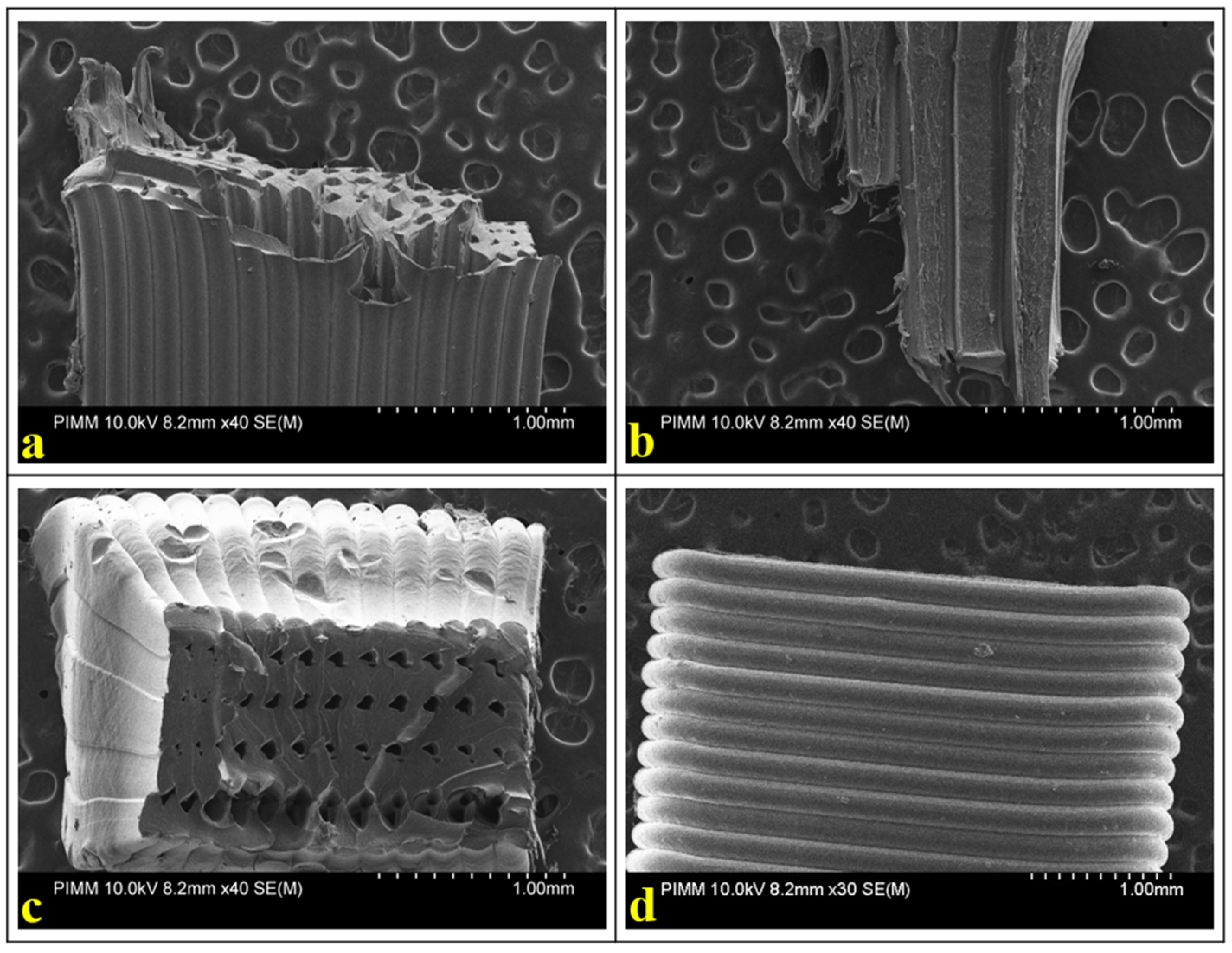
3.3.1. Microscopic Observation

To examine the microstructure of the material in 3D printed specimens, we carried out microscopic observations using a Scanning Electron Microscope (HITACHI 4800 SEM).

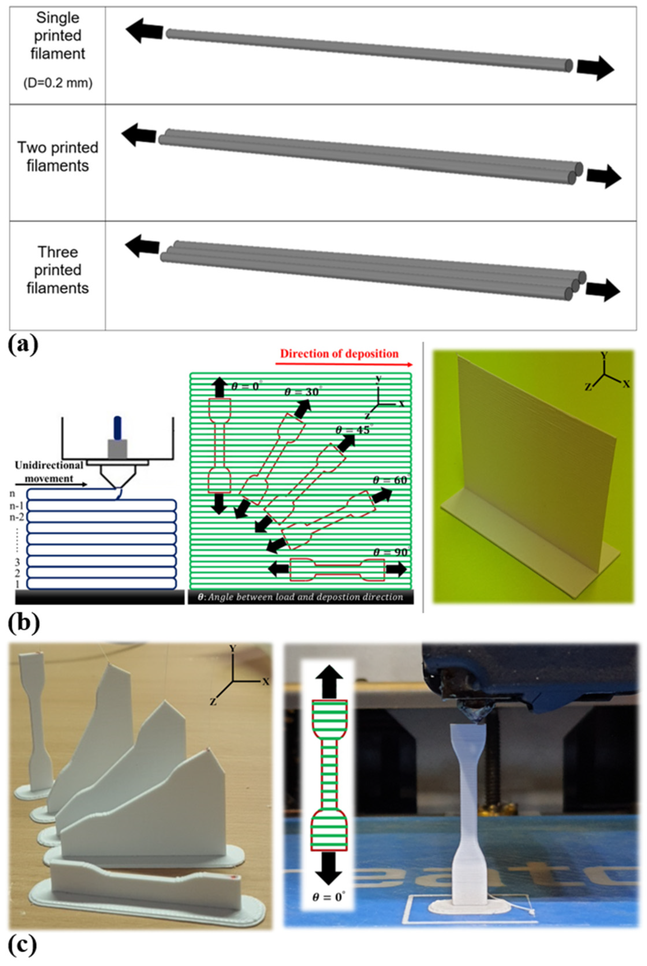
3.3.2. Quasi-Static Tensile Test and Specimen Preparation

Tensile tests until failure were conducted in accordance with ASTM D638 type IV standard at room temperature. A hydraulic machine, an MTS 830, equipped with a 10 kN load cell and self-tightening jaws, was employed for all specimen series. Initially, the quasi-static tensile specimens were created by cutting them from the printed solid blocks (Figure 2b) using a standard mold and a press machine. Subsequently, tensile tests were performed on the printed specimens at a velocity of 1 mm/min, following the standard (Figure 2c). Notably, a non-contact method, utilizing a camera, was employed to measure local deformations parallel to the tensile test. Displacement (measured in millimeters) and force (measured in Newtons) were collected and processed through MTS Test Suite software to construct tensile strain–stress curves and determine the tensile properties, which include Young’s modulus, tensile strength, and strain at break. The Young’s modulus was determined from the slope of the stress–strain curves obtained. Tensile strength was calculated by dividing the maximum applied load by the cross-sectional area of the specimen. The strain at break was measured using a non-contact extensometer. All reported values represent averages obtained from five specimens.
Furthermore, tensile tests were also conducted on the single printed filament (as illustrated in Figure 2a). This additional step aimed to gain insight into how bonding and filament deposition affect the tensile behavior of the printed specimens.

4. Results and Discussions

4.1. Quasi-Static Tensile Behavior of 3D Printed Specimens

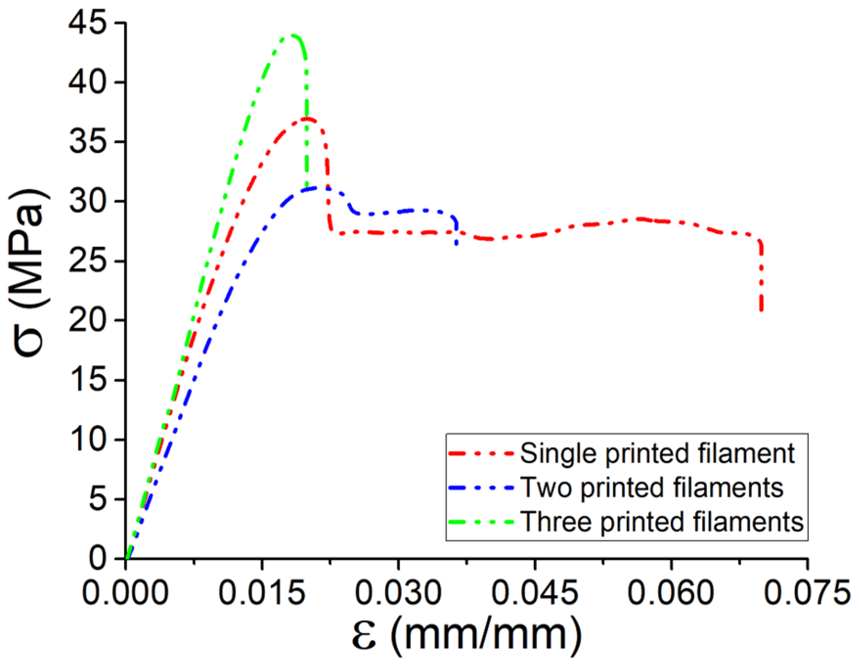
4.1.1. PLA Filaments

In Figure 3, the results of the tensile tests for one printed filament, two printed filaments, and three printed filaments are presented. The Young’s modulus, which measures the stiffness of the material, shows no significant difference among these specimens. However, notable variations are observed in the failure strain and maximum stress. It is worth mentioning that as the number of printed layers increases, the failure strain decreases, indicating a more brittle behavior in the printed PLA filament. Simultaneously, the maximum stress increases, suggesting a higher resistance to deformation before failure. This shift in mechanical properties implies that the PLA filament becomes more prone to brittleness as the printing process advances. A specific observation is made regarding the failure strain of the single printed filament, which is significantly higher (~7.5%) compared to the three printed filaments (~2%). This substantial decrease in failure strain indicates that the printed filaments are more susceptible to breaking or fracturing at lower strain levels than the original spool.
Accordingly, the mechanical behavior, particularly the elongation (failure strain), in the early stages of failure is significantly influenced by the number of layers in the 3D printing process. These results imply that understanding these changes is crucial for optimizing the 3D printing process and predicting the mechanical properties of the 3D printed material as also observed in our previous work [29].

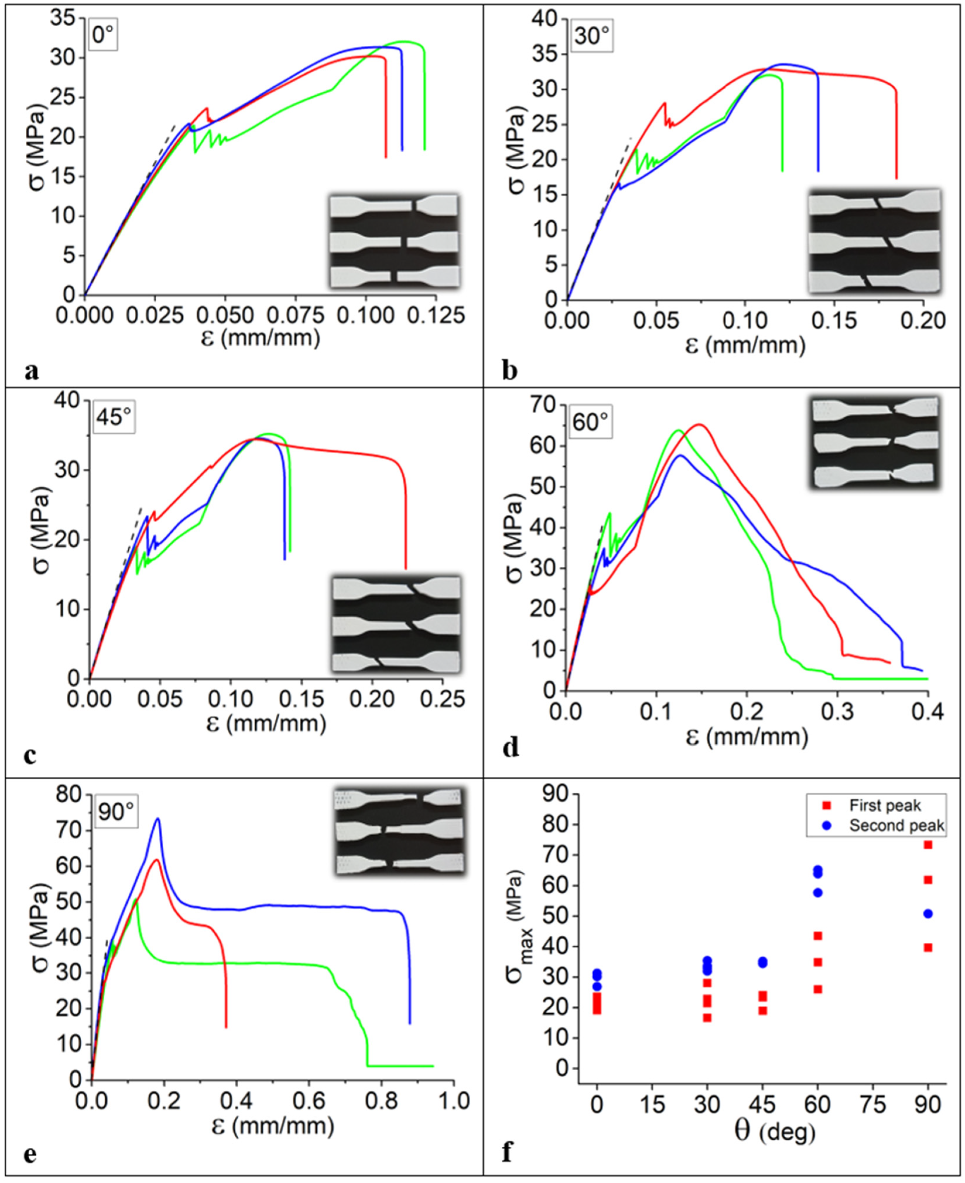
4.1.2. Impact of Filament Orientation on the Tensile Behavior (3D Printed Vertical Walls)

Tensile behaviors of the set of specimens cut from the vertical wall are illustrated in Table 2 including the tensile behavior at different orientations. The results indicate that the ultimate strength increases when the orientation angle increases, during which the influence of the deposition direction is more significant. The highest ultimate strength and Young’s modulus belong to the specimens of the printed solid blocks at the angle of 90°. These observations refer to the fact that the increase in the defined angle increases the strength of the material; however, there would be an optimized zone regarding the strength and ductility of the material according to its orientation angle. At this stage, the following observations could be summarized:
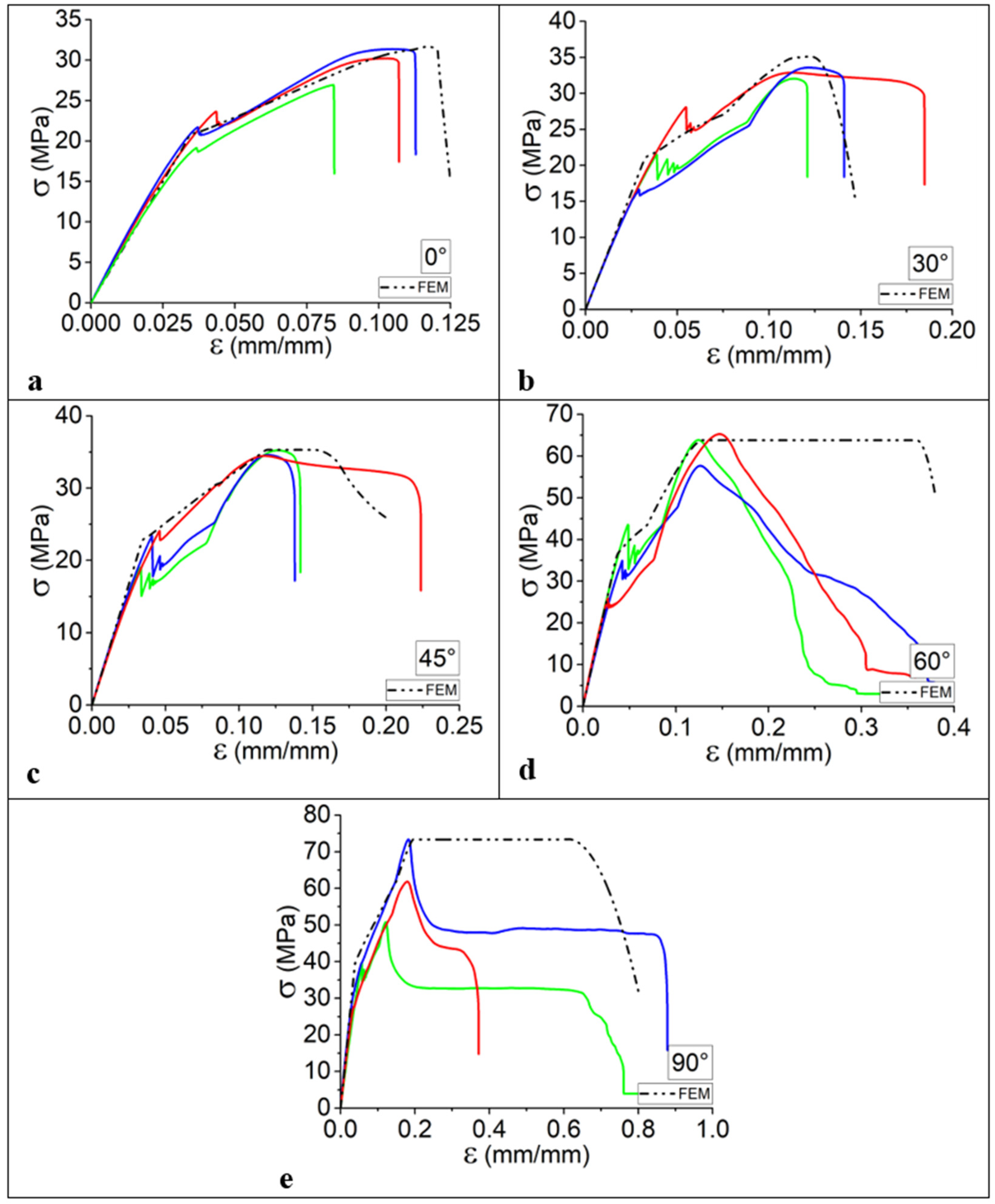
  • The higher the orientation angle, the higher the strength of the material.
  • The higher the orientation angle, the higher the ductility.
  • When the orientation angle is increased, Young’s modulus increases by about 40%.
  • When the orientation angle is increased, Ductility increases by about 70%.
In general, a variation in orientation angle changes the Young’s modulus, ultimate strength, and ductility of the material.
Examining the outcomes derived from the evaluation of specimens obtained by sectioning a 3D printed vertical wall at various orientation angles, a discernible trend emerges wherein an augmentation in the orientation angle corresponds to an enhancement in the mechanical properties of the printed components. This trend yields favorable findings that underscore the impact of orientation on mechanical behavior. However, despite these advancements, the persisting challenge lies in addressing the asymmetry inherent in the filament deposition mechanism.
In the context of filament deposition, the issue of symmetry poses a persistent obstacle, warranting meticulous consideration. It is imperative to acknowledge and account for not only the orientation of 3D printed geometries but also the myriad variables inherent in the overall 3D printing process. This encompasses a comprehensive understanding of factors related to materials, the intricacies of the printing procedure, and the underlying physical phenomena that influence the 3D printing process. An in-depth exploration of these multifaceted elements is essential for advancing the precision and efficacy of 3D printed structures, thereby contributing to the refinement of 3D printing technologies.

4.1.3. Quasi-Static Tensile Behavior of 3D Printed Specimens in Various Orientations

The quasi-static tensile behavior of at least five 3D printed specimens per orientation angle, adhering to the applied ASTM standard, is systematically elucidated in Figure 4 across a spectrum of orientation angles. As delineated in Figure 4a–e, distinct mechanical behaviors manifest, showcasing either brittle failures characterized by low Young’s modulus or ductile failures accompanied by an elevation in ultimate strength. This diversity in behavior is intricately linked to the previously discussed single filament deposition mechanism in the z-direction, underscoring the inevitable influence of layer deposition on mechanical properties. The nuanced exploration of angle orientation, spanning from 0° to 90°, unveils a conspicuous augmentation in the material’s ductility. This observed increase in ductility with varying orientation angles signifies a critical insight into the influence of orientation on the material’s deformation characteristics. Conversely, a noteworthy trend surfaces as the orientation angle increases: a proportional escalation in ultimate strength. This correlation suggests that an orientation angle of 90° may be deemed optimal for the construction of components, striking a balance between heightened ductility and superior ultimate strength.
However, even within this seemingly optimal orientation, a lingering challenge persists in the form of asymmetry across three axes. The realization of symmetry in 3D printed structures remains an intricate hurdle, necessitating further exploration and potential innovations to refine the mechanical performance and structural integrity of additively manufactured components. The juxtaposition of ductility and ultimate strength, as influenced by orientation angles, provides valuable insights for advancing the precision and reliability of 3D printed parts.
The intriguing observation emerges that, within each specific orientation angle, distinct behaviors are discernible based on the corresponding tensile curves. This variance is attributed to the inherent non-uniformity during the filament deposition stage, where the homogeneity of filament distribution is not guaranteed. Diverse bonding scenarios between the deposited layers contribute to the observed differences in mechanical responses. It is postulated that rheological and viscosity variations are pivotal factors influencing the bonding dynamics and overall strength of the constructed components [30,31].
Illustratively, a noteworthy phenomenon is evident in the variability in ultimate strength during the initial peak of the tested specimens while concurrently maintaining a consistent Young’s modulus. This discrepancy in ultimate strength underscores the nuanced interplay between deposition conditions, rheological properties, and the resulting mechanical performance. Furthermore, it is crucial to highlight the presence of two distinct peaks in the ultimate strength, which is indicative of a bifurcated failure mechanism. The initial peak signifies the point at which certain filaments undergo failure, resulting in a reduction in overall strength, while others persist in resisting until their eventual failure. This dual-peak manifestation elucidates the complex interdependence of material properties and deposition dynamics, necessitating a comprehensive understanding of the optimization of 3D printing processes and the advancement of AM technologies.
In addition, as depicted in Figure 4f, the discernible influence of interlayer bonding becomes evident, thereby underscoring a noteworthy correlation between the ultimate strength of the material and the escalating orientation angle. As expounded upon in the antecedent section, it is noteworthy to emphasize that the variance in ultimate strength is more pronounced with higher orientation angles. This phenomenon is rooted in the pivotal role played by the failure mechanism, wherein the point of failure manifests predominantly at the interface of deposited layers when the orientation angle is at its zenith (θ = 0°). This occurrence leads to a concomitant reduction in the ultimate strength and, consequently, a sequential cascade of failures in the interlayer bonding.
SEM micrographs depicting fractured specimens with varying filament orientations have been systematically analyzed to elucidate the profound impact of filament alignment on the mechanical characteristics of the specimens under investigation. In order to delineate distinctions in failure modes corresponding to the exhibited tensile behavior, Figure 5a–c portrays the fracture surfaces of specimens printed with a 90° orientation, while Figure 5d illustrates counterparts printed with a 0° orientation.
Microscopic analysis reveals a distinctive failure mechanism for specimens printed with a 0° orientation, where bonding formation serves as the focal point of failure, resulting in a characteristic brittle surface fracture. In stark contrast, specimens printed with a 90° orientation exhibit a noteworthy shift toward ductile behavior as the predominant failure mode, which is indicative of robust filament strength. This transition can be attributed to the parallel alignment of the tensile direction with the filament direction, colloquially referred to as the direction of deposition. Consequently, this alignment engenders a shift in the failure mode from brittle to ductile, wherein each filament undergoes failure during the tensile test, underscoring a marked alteration in the material’s failure characteristics.

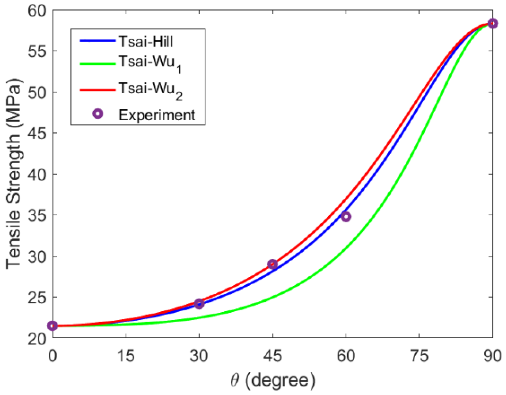
4.2. Validation of Tsai–Hill and Tsai–Wu Models

The independent parameter values derived from the quasi-static tensile tests conducted on the 3D printed specimens manifest a robust agreement between the predicted and measured yield points across diverse build orientations [32]. To visually underscore this concordance, the outcomes of our experiments are graphically represented against the predicted failures in Figure 6. Remarkably, both the Tsai–Wu and Tsai–Hill equations exhibit a commendable capacity to accurately anticipate yield points under singular input parameters for pure tensile loads. This precision in prediction holds significance, especially given the inherent variability in the 3D printing process, marked by fluctuations in filament diameter and susceptibility to ambient conditions. The graphical representation attests to the efficacy of these equations, portraying consistent alignment between predicted and observed outcomes amidst the intricate variables intrinsic to the FFF process [33].
It is noteworthy that the failure modes exhibited by the 3D printed specimens are diverse, encompassing both brittle and ductile fractures. Specifically, the Polylactic Acid (PLA) specimens demonstrate a transition from ductile failure at low build orientations to predominantly ductile failure at high build orientations. This shift in failure mode is intricately linked to an augmentation in the ultimate strength of the constructed materials, thereby highlighting the nuanced influence of build orientation on the failure characteristics of 3D printed components.
Both the Tsai–Hill and Tsai–Wu models exhibit commendable efficacy in predicting the ultimate strength across various build orientations. However, it is crucial to note that Tsai–Wu1 implements an increase in prediction error. Consequently, we recommend the preferential utilization of either the Tsai–Hill or Tsai–Wu2 criteria for accurate prediction of tensile strength in materials subjected to our experimental conditions. An in-depth evaluation of predictive accuracy suggests that, while a predictive error of less than 20% is generally deemed acceptable for materials of variable nature, the model consistently aligns with its direction of error. This consistency in error direction enhances the reliability of the model’s predictions. Notably, the model tends to adopt a conservative stance in estimating ultimate stress, an outcome that augurs well for the design process as it promotes safety. The outcomes derived from our study effectively capture the nuanced impact of build orientation, with both criteria underscoring the pivotal role of this parameter in determining material performance. It is pertinent to highlight that previous research efforts in this domain often relied on a singular criterion, thereby limiting the precision and applicability of their findings [34,35]. In contrast, our approach utilizes both Tsai–Hill and Tsai–Wu2 criteria, allowing for a more comprehensive integration of multiple phenomena and ensuring a more robust and inclusive understanding of the predictive capabilities of these models.
The mechanical behavior of 3D printed parts is profoundly influenced by the orientation of the deposited layers during 3D printing process. This phenomenon arises from the anisotropic nature of the layer-wise construction, wherein the material properties exhibit directional dependencies. The orientation of the layers plays a pivotal role in determining the strength, stiffness, and other mechanical characteristics of the final printed object. Research studies have consistently demonstrated that the mechanical properties can vary significantly based on the build orientation. One key aspect affected by layer orientation is the tensile strength of 3D printed parts. In general, parts printed with layers parallel to the loading direction often exhibit higher tensile strength compared to those with perpendicular or inclined layer orientations. This anisotropic behavior is attributed to the layer bonding mechanism, where the interlayer adhesion is typically weaker than the intra-layer bonding. Consequently, the load-bearing capacity along the layer lines tends to be superior, influencing the overall tensile strength of the printed component [36,37].
Moreover, the impact strength of 3D printed parts is also subject to variation based on layer orientation. The research findings indicate that parts printed with layers parallel to the impact direction may demonstrate improved impact resistance compared to those with different orientations. This is due to the layering effect, which can either enhance or diminish the ability of the material to absorb and distribute impact energy, depending on the layer orientation. The anisotropic mechanical behavior resulting from layer orientation has implications for the design and structural integrity of 3D printed components. Engineers and designers must carefully consider the intended application and loading conditions when choosing the optimal orientation for printing. While advancements in printing technologies and material formulations aim to mitigate some of these challenges, understanding and characterizing the effects of layer orientation on mechanical properties remain essential for the continued development and widespread adoption of 3D printed parts across diverse industries [38].
The proposed approach offers a notable advantage by providing the capacity to predict the tensile strength of diverse materials, mitigating the need for excessive testing and subsequently reducing the number of required experimental tests. Furthermore, it is noteworthy that this approach facilitates the prediction of material behavior across various orientations, thereby enabling the tailored design of geometry for the specific application of 3D printed parts.

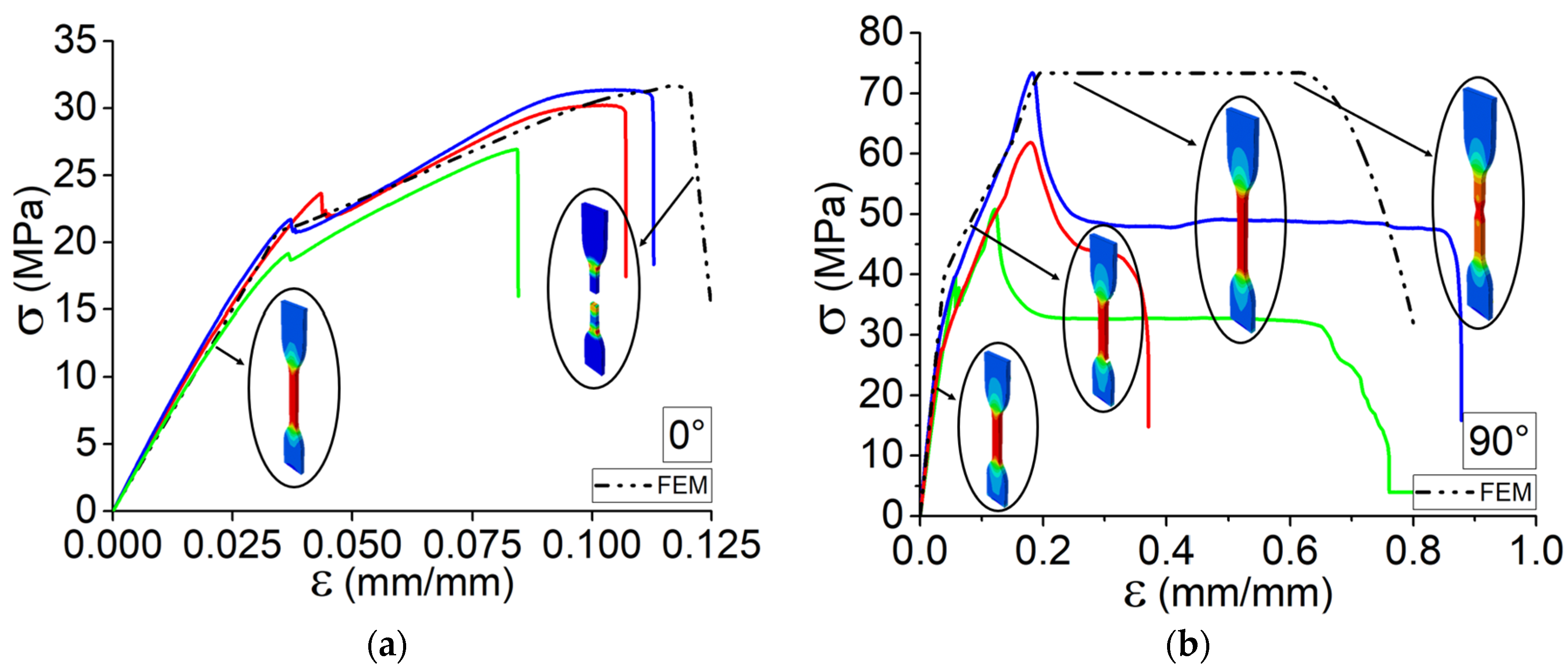
4.3. Finite Element Analysis

Finite Element Analysis (FEA) serves as a robust numerical methodology, offering a virtual platform for the representation of structures and materials, thereby facilitating the accurate prediction of their mechanical responses across diverse conditions. The meticulous comparison between FEA results and experimental data, as depicted in Figure 7a–e, elucidates a noteworthy concordance between the anticipated and empirically observed mechanical behaviors across varying orientation angles. Nevertheless, a discerning analysis of tensile behavior reveals nuanced distinctions when scrutinizing both modalities under different orientation angles.
As expounded upon in preceding sections, the intricacies in mechanical responses are intimately associated with filament orientation and deposition direction, denoted by symmetry in distinct directions. This emphasizes the underlying rationale for the observed disparities between FEA predictions and experimental outcomes, particularly pronounced with an augmentation in the orientation angle. The manifestation of these nuanced differences underscores the importance of a comprehensive understanding of filament orientation effects in the accurate simulation of mechanical behaviors. The fidelity of FEA predictions in capturing the mechanical intricacies necessitates meticulous consideration of orientation angles, ensuring a nuanced interpretation of the simulation results vis-à-vis experimental observations.
Notably, for θ = 0°, the FEA aligns well with the experimental results, showcasing a congruence in the prediction of elongation and ultimate strength. Conversely, at θ = 90°, a substantial disparity emerges, particularly in the elongation and ultimate strength of the 3D printed specimens. This deviation can be attributed to the evolving symmetry and structural characteristics associated with the changing orientation angle. The amplification of differences in mechanical behavior with increasing orientation angles serves as a critical observation, shedding light on the nuanced interplay between filament alignment and structural response. As such, the fidelity of FEA predictions appears contingent upon a comprehensive understanding of the interrelated factors influencing mechanical behavior in 3D printed materials. This recognition underscores the need for refined modeling approaches that can capture the intricate effects of orientation on mechanical properties, paving the way for more accurate simulations and design considerations in additive manufacturing processes.
Undoubtedly, concerted efforts have been directed toward elucidating the outcomes of FEM and experimental analyses, specifically focusing on the orientations θ = 0° and θ = 90°. The accurate prediction of failure modes assumes particular significance, given the distinct elasticity and plasticity exhibited under each condition (Figure 8). Consequently, it becomes imperative to meticulously consider and assimilate the observed behaviors into a broader analysis framework. Moreover, a multifaceted perspective can be gleaned by cross-referencing the predicted outcomes with SEM micrographs depicted in Figure 5. This comparative analysis serves as an additional layer of validation and enhances the comprehensiveness of our findings. These micrographs offer a visual representation, allowing for a nuanced examination of the material’s elongation at θ = 90°, as expertly illustrated in Figure 5a–c. This representation effectively captures the material’s resistance, which is particularly noteworthy as the deposited layers align with the tensile test direction, providing valuable insights into the interplay between orientation and mechanical properties.

5. Perspective: Interaction of Parameters

The impact of filament orientation in 3D printing represents a crucial aspect that warrants thoughtful consideration in the pursuit of optimization objectives. Filament orientation plays a pivotal role in determining the mechanical properties and overall performance of the printed components. Understanding and strategically manipulating this factor can significantly influence the final product’s strength, durability, and functionality. In AM, the orientation of filaments within the printed layers interacts intricately with various parameters such as layer thickness, infill density, and printing speed. These interdependencies necessitate a holistic perspective when seeking to optimize the printing process. It is essential to recognize that isolated adjustments to a single parameter may not yield the desired outcomes, as the filament orientation dynamically interacts with other printing variables.
Achieving optimal results requires a comprehensive understanding of the nuanced relationships between filament orientation and other printing parameters. By adopting a systematic approach that considers the synergistic effects of these variables, manufacturers can enhance the mechanical integrity and overall quality of 3D printed objects. This perspective underscores the importance of a holistic optimization strategy that acknowledges the intricate interplay of filament orientation and various parameters in the 3D printing process.

6. Conclusions

In Additive Manufacturing, a process integral to the direct fabrication of components from 3D models, it becomes imperative to systematically enhance the mechanical characteristics of the produced parts. This study is dedicated to elucidating the nuanced influence of the orientation of deposited layers on the mechanical properties of 3D printed Polylactic Acid (PLA) components. Our methodology integrates experimental testing and predictive modeling utilizing the Tsai–Hill and Tsai–Wu criteria. The predicted ultimate strength derived from both criteria exhibits commendable agreement with the physical 3D printed specimens across a spectrum of orientation angles. Concurrently, Finite Element Simulations are meticulously conducted to anticipate the mechanical behavior, accounting for observed elasticity and plasticity in various orientations. Our observations unveil a substantial increase in Young’s modulus and ductility/elongation—40% and 70%, respectively—during the transition from θ = 0° to θ = 90°. Additionally, the ultimate strength experiences a notable increase, leading to diverse failure modes contingent upon θ. These findings underscore the pivotal role of layer orientation in shaping the anisotropic behavior of 3D printed PLA components. The SEM micrographs validate the observed results, particularly the elongation observed for the printed specimen at θ = 90°.
This study furnishes valuable insights for professionals in engineering, design, and manufacturing who seek to harness the advantages of 3D printing technology while ensuring that the mechanical integrity of 3D printed objects aligns with their functional requirements. It accentuates the critical consideration of orientation as a design parameter in the pursuit of optimization objectives.

Author Contributions

Conceptualization, A.E.M. and K.R.; Methodology, S.V. and H.R.V.; Software, M.R.; Validation, M.R.; Formal analysis, H.R.V.; Investigation, S.V. and H.R.V.; Resources, H.R.V. and A.T.; Writing—original draft, H.R.V.; Writing—review & editing, S.V., M.R., A.E.M. and K.R.; Visualization, A.E.M. and K.R.; Supervision, K.R. and A.T.; Project administration, A.T.; Funding acquisition, A.T. All authors have read and agreed to the published version of the manuscript.

Funding

This research received no external funding.

Data Availability Statement

Data is contained within the article.

Conflicts of Interest

The authors declare no conflict of interest.

References

  1. Utela, B.; Storti, D.; Anderson, R.; Ganter, M. A review of process development steps for new material systems in three dimensional printing (3DP). J. Manuf. Process. 2008, 10, 96–104. [Google Scholar] [CrossRef]
  2. Gebisa, A.W.; Lemu, H.G. Investigating Effects of Fused-Deposition Modeling (FDM) Processing Parameters on Flexural Properties of ULTEM 9085 using Designed Experiment. Materials 2018, 11, 500. [Google Scholar] [CrossRef] [PubMed]
  3. Mohamed, O.A.; Masood, S.H.; Bhowmik, J.L. Optimization of fused deposition modeling process parameters: A review of current research and future prospects. Adv. Manuf. 2015, 3, 42–53. [Google Scholar] [CrossRef]
  4. Jiang, S.; Liao, G.; Xu, D.; Liu, F.; Li, W.; Cheng, Y.; Li, Z.; Xu, G. Mechanical properties analysis of polyetherimide parts fabricated by fused deposition modeling. High Perform. Polym. 2018, 31, 97–106. [Google Scholar] [CrossRef]
  5. Chennakesava, S.; Narayan, Y.S. Fused deposition modeling—Insights. In Proceedings of the International Conference on Ad-vances in Design and Manufacturing ICAD&M, Herceg Novi, Montenegro, 29 May–1 June 2014. [Google Scholar]
  6. Peng, F.; Vogt, B.; Cakmak, M. Complex Flow and Temperature History during Melt Extrusion in Material Extrusion Additive Manufacturing. Addit. Manuf. 2018, 22, 197–206. [Google Scholar] [CrossRef]
  7. Mackay, M.E.; Swain, Z.R.; Banbury, C.R.; Phan, D.D.; Edwards, D.A.; Ma, T.; Yang, R.; Zheng, Z.; Song, Y.; Del Giudice, F.; et al. The performance of the hot end in a plasticating 3D printer. J. Rheol. 2017, 61, 229–236. [Google Scholar] [CrossRef]
  8. Bellini, A.; Güçeri, S. Mechanical characterization of parts fabricated using fused deposition modeling. Rapid Prototyp. J. 2003, 9, 252–264. [Google Scholar] [CrossRef]
  9. Vanaei, H.R.; Raissi, K.; Deligant, M.; Shirinbayan, M.; Fitoussi, J.; Khelladi, S.; Tcharkhtchi, A. Toward the understanding of temperature effect on bonding strength, dimensions and geometry of 3D-printed parts. J. Mater. Sci. 2020, 55, 14677–14689. [Google Scholar] [CrossRef]
  10. Vanaei, H.R.; Shirinbayan, M.; Deligant, M.; Raissi, K.; Fitoussi, J.; Khelladi, S.; Tcharkhtchi, A. Influence of process parameters on thermal and mechanical properties of polylactic acid fabricated by fused filament fabrication. Polym. Eng. Sci. 2020, 60, 1822–1831. [Google Scholar] [CrossRef]
  11. Rodríguez, J.F.; Thomas, J.P.; Renaud, J.E. Design of fused-deposition ABS components for stiffness and strength. J. Mech. Des. 2003, 125, 545–551. [Google Scholar] [CrossRef]
  12. D’amico, A.; Peterson, A.M. An adaptable FEA simulation of material extrusion additive manufacturing heat transfer in 3D. Addit. Manuf. 2018, 21, 422–430. [Google Scholar] [CrossRef]
  13. Yardimci, M.A.; Güçeri, S. Conceptual framework for the thermal process modelling of fused deposition. Rapid Prototyp. J. 1996, 2, 26–31. [Google Scholar] [CrossRef]
  14. Prajapati, H.; Ravoori, D.; Woods, R.L.; Jain, A. Measurement of anisotropic thermal conductivity and inter-layer thermal contact resistance in polymer fused deposition modeling (FDM). Addit. Manuf. 2018, 21, 84–90. [Google Scholar] [CrossRef]
  15. Vidakis, N.; Petousis, M.; Velidakis, E.; Liebscher, M.; Mechtcherine, V.; Tzounis, L. On the Strain Rate Sensitivity of Fused Filament Fabrication (FFF) Processed PLA, ABS, PETG, PA6, and PP Thermoplastic Polymers. Polymers 2020, 12, 2924. [Google Scholar] [CrossRef] [PubMed]
  16. Vidakis, N.; David, C.; Petousis, M.; Sagris, D.; Mountakis, N.; Moutsopoulou, A. The effect of six key process control parameters on the surface roughness, dimensional accuracy, and porosity in material extrusion 3D printing of polylactic acid: Prediction models and optimization supported by robust design analysis. Adv. Ind. Manuf. Eng. 2022, 5, 100104. [Google Scholar] [CrossRef]
  17. Beattie, N.; Bock, N.; Anderson, T.; Edgeworth, T.; Kloss, T.; Swanson, J. Effects of Build Orientation on Mechanical Properties of Fused Deposition Modeling Parts. J. Mater. Eng. Perform. 2021, 30, 5059–5065. [Google Scholar] [CrossRef]
  18. Balderrama-Armendariz, C.O.; MacDonald, E.; Espalin, D.; Cortes-Saenz, D.; Wicker, R.; Maldonado-Macias, A. Torsion analysis of the anisotropic behavior of FDM technology. Int. J. Adv. Manuf. Technol. 2018, 96, 307–317. [Google Scholar] [CrossRef]
  19. Casavola, C.; Cazzato, A.; Moramarco, V.; Pappalettere, C. Orthotropic mechanical properties of fused deposition modelling parts described by classical laminate theory. Mater. Des. 2016, 90, 453–458. [Google Scholar] [CrossRef]
  20. Somireddy, M.; Czekanski, A.; Singh, C.V. Development of constitutive material model of 3D printed structure via FDM. Mater. Today Commun. 2018, 15, 143–152. [Google Scholar] [CrossRef]
  21. Domingo-Espin, M.; Puigoriol-Forcada, J.M.; Garcia-Granada, A.-A.; Llumà, J.; Borros, S.; Reyes, G. Mechanical property characterization and simulation of fused deposition modeling Polycarbonate parts. Mater. Des. 2015, 83, 670–677. [Google Scholar] [CrossRef]
  22. Al Abadi, H.; Thai, H.-T.; Paton-Cole, V.; Patel, V. Elastic properties of 3D printed fibre-reinforced structures. Compos. Struct. 2018, 193, 8–18. [Google Scholar] [CrossRef]
  23. Hill, R. A Theory of the Yielding and Plastic Flow of Anisotropic Metals. Proc. R. Soc. Lond. Ser. A Math. Phys. Sci. 1948, 193, 281–297. [Google Scholar]
  24. Rodrigues, D.; Belinha, J.; Jorge, R.N.; Dinis, L. Development of a constitutive model to predict the elasto-plastic behaviour of 3D-printed thermoplastics: A meshless formulation. Addit. Manuf. Hybrid Process. Compos. Syst. 2020, 129, 311–329. [Google Scholar]
  25. Bandinelli, F.; Peroni, L.; Morena, A. Elasto-Plastic Mechanical Modeling of Fused Deposition 3D Printing Materials. Polymers 2023, 15, 234. [Google Scholar] [CrossRef] [PubMed]
  26. Tsai, S.W. Strength Characteristics of Composite Materials; NASA: Washington, DC, USA, 1965. [Google Scholar]
  27. Vanaei, H.R.; Khelladi, S.; Deligant, M.; Shirinbayan, M.; Tcharkhtchi, A. Numerical Prediction for Temperature Profile of Parts Manufactured using Fused Filament Fabrication. J. Manuf. Process. 2022, 76, 548–558. [Google Scholar] [CrossRef]
  28. Vanaei, H.R.; Khelladi, S.; Tcharkhtchi, A. Roadmap: Numerical-Experimental Investigation and Optimization of 3D-Printed Parts Using Response Surface Methodology. Materials 2022, 15, 7193. [Google Scholar] [CrossRef] [PubMed]
  29. Vanaei, H.R.; Shirinbayan, M.; Vanaei, S.; Fitoussi, J.; Khelladi, S.; Tcharkhtchi, A. Multi-scale damage analysis and fatigue behavior of PLA manufactured by fused deposition modeling (FDM). Rapid Prototyp. J. 2021, 27, 371–378. [Google Scholar] [CrossRef]
  30. Wu, W.; Ye, W.; Geng, P.; Wang, Y.; Li, G.; Hu, X.; Zhao, J. 3D printing of thermoplastic PI and interlayer bonding evaluation. Mater. Lett. 2018, 229, 206–209. [Google Scholar] [CrossRef]
  31. Kuba, D.; Matsuzaki, R.; Ochi, S.; Ogihara, S. 3D printing of composite materials using ultralow-melt-viscosity polymer and continuous carbon fiber. Compos. Part C Open Access 2022, 8, 100250. [Google Scholar] [CrossRef]
  32. Eryildiz, M. Effect of Build Orientation on Mechanical Behaviour and Build Time of FDM 3D-Printed PLA Parts: An Experimental Investigation. Eur. Mech. Sci. 2021, 5, 116–120. [Google Scholar] [CrossRef]
  33. Yao, T.; Ye, J.; Deng, Z.; Zhang, K.; Ma, Y.; Ouyang, H. Tensile failure strength and separation angle of FDM 3D printing PLA material: Experimental and theoretical analyses. Compos. Part B Eng. 2020, 188, 107894. [Google Scholar] [CrossRef]
  34. Zhao, Y.; Chen, Y.; Zhou, Y. Novel mechanical models of tensile strength and elastic property of FDM AM PLA materials: Experimental and theoretical analyses. Mater. Des. 2019, 181, 108089. [Google Scholar] [CrossRef]
  35. Yao, T.; Deng, Z.; Zhang, K.; Li, S. A method to predict the ultimate tensile strength of 3D printing polylactic acid (PLA) materials with different printing orientations. Compos. Part B Eng. 2019, 163, 393–402. [Google Scholar] [CrossRef]
  36. Rankouhi, B.; Javadpour, S.; Delfanian, F.; Letcher, T. Failure Analysis and Mechanical Characterization of 3D Printed ABS With Respect to Layer Thickness and Orientation. J. Fail. Anal. Prev. 2016, 16, 467–481. [Google Scholar] [CrossRef]
  37. Gonabadi, H.; Yadav, A.; Bull, S.J. The effect of processing parameters on the mechanical characteristics of PLA produced by a 3D FFF printer. Int. J. Adv. Manuf. Technol. 2020, 111, 695–709. [Google Scholar] [CrossRef]
  38. Ćwikła, G.; Grabowik, C.; Kalinowski, K.; Paprocka, I.; Ociepka, P. The influence of printing parameters on selected mechanical properties of FDM/FFF 3D-printed parts. IOP Conf. Ser. Mater. Sci. Eng. 2017, 227, 012033. [Google Scholar] [CrossRef]
Figure 1. Model of isotropic materials for modeling objectives.
Machines 11 01086 g001
Figure 2. Representation of (a) proposed filaments for tensile test, (b) location of specimens on the printed solid blocks, and (c) printed specimens in different orientations.
Machines 11 01086 g002
Figure 3. Tensile curves of different formed filaments.
Machines 11 01086 g003
Figure 4. (ae) Quasi-static tensile behavior and (f) ultimate strength (σmax) of 3D printed specimens for various orientations.
Machines 11 01086 g004
Figure 5. SEM micrograph for (ac) specimens printed at θ = 90° and (d) θ = 0°.
Machines 11 01086 g005
Figure 6. Comparison of the Tsai–Wu and Tsai–Hill models with the build orientation data.
Machines 11 01086 g006
Figure 7. (ae) Comparison between FEM results and experimental test data of 3D printed specimens for various orientations.
Machines 11 01086 g007
Figure 8. Comparison between FEM results and experimental test data of 3D printed specimens during tensile test for (a) θ = 0° and (b) θ = 90°.
Machines 11 01086 g008
Table 1. Physico-chemical properties of PLA filament (Adapted from manufacturer datasheet).
PropertiesTypical Value
Material density1.24 g/cm3
Diameter (tolerance)1.75 mm (±0.01 mm)
Glass transition temperature72 °C
Crystallization temperature103 °C
Melting temperature158 °C
Table 2. Quasi-static tensile behavior of specimens cut from vertical walls printed for various orientations.
OrientationE (GPa)Yield Strength (MPa) ε f (mm/mm)
0.6 ± 0.05220 ± 1.150.11 ± 0.019
30°0.7 ± 0.04625 ± 1.050.15 ± 0.014
45°0.9 ± 0.05030 ± 1.090.17 ± 0.017
60°1.0 ± 0.05450 ± 1.170.35 ± 0.022
90°1.1 ± 0.04865 ± 1.060.6 ± 0.21
Disclaimer/Publisher’s Note: The statements, opinions and data contained in all publications are solely those of the individual author(s) and contributor(s) and not of MDPI and/or the editor(s). MDPI and/or the editor(s) disclaim responsibility for any injury to people or property resulting from any ideas, methods, instructions or products referred to in the content.

