1. Introduction
The additive manufacturing market is expected to be a powerful force in the manufacturing industry, with a heavy focus on infill patterns as a key field of growth [
1]. A rising issue in materials science is that these patterns create more of a challenge to provide for both the strength and resilience of the parts [
2]. The aspects of bioinspired design can be used as a gateway to incorporate sustainable design into material structure functionalities [
3]. Currently, there are limited concepts designers can use to design or construct material structures with bioinspired designs [
4]. While bioinspired infill designs have become more widespread, there needs to be more exploration into this area of additive manufacturing [
5]. This creates the opportunity for designing, creating, and testing bioinspired infill patterns for material structures that achieve desired values for the strength and resilience of the structures [
6]. And adds value to the industry of additive manufacturing through material architecture design [
7].
Bioinspired design can be described as learning from nature’s concepts and design principles to derive inspiration for a problem [
8,
9]. Recent research is driving a shift in modern materials sciences and additive manufacturing [
10,
11,
12]. Yang et al. formulated many different areas within additive manufacturing that could be expanded with the use of bioinspired designs, yet only provides a general context to the industry of additive manufacturing, with not much focus on the aspects of bioinspired design on infill patterns [
13]. Infill patterns are the patterns that conform to the interior of a 3D-printed object, and have a significant effect on the object’s print time, filament consumption, flexibility, strength, weight, and what the object can be used for [
2]. Studies based on current 3D material structures have been conducted using different infill patterns [
2,
14,
15,
16,
17,
18,
19]. These studies compare different infill patterns to each other through simulated and experimental analysis across a range of properties, such as tensile strength, compressive strength, and surface roughness, as well as for different materials such as ABD, PLA, and cPLA. While these studies provide a general understanding of the relationships between different infill patterns and the properties of each, they do not take into consideration infill patterns derived using bioinspired design.
Podroužek et al. performed a comparison test of 14 different infill patterns for additive manufacturing and structural applications to determine the compression strengths relative to one another [
20]. In their study, they illustrate the differences between the classical 2D structures such as honeycomb structures and the Gyroid 3D structures. In the findings of the study, they determined that the 2D structures provide greater compression and strength along one axis compared to the 3D patterns, yet offer less support along all dimensions due to the nature of the patterns [
20]. One study that focuses on bioinspired infill pattern designs provides details on optimization for specific properties such as strength and resilience through the use of cellular or lattice structures, but does not provide information on the opportunities for more bioinspired infill pattern designs and how they can be used to increase strength of structures [
3]. The work of Hmeidat et al. addresses this gap by investigating the physical properties of different infill patterns, both bioinspired and non-bioinspired patterns, showing that stiffness varied by up to 22% between different infill patterns and that failure load varied by up to 426% between structures printed with various infill patterns [
6]. These percentages indicate the variability associated with each infill pattern, but offer insight into what patterns perform the best and how they compare against certain bioinspired designs.
Inspired by lightweight but strong bone structures found in nature, Wu et al. examined bone-like porous structures as a model for additive manufacturing infill patterns [
7]. One important aspect gained from this study is that the material distribution across the design was optimized for external loading conditions which maximizes the stiffness of the structures [
7]. This resulted in an irregular variational density in the porous infill pattern. Inspired by the properties of wood, Zorzetto et al. investigated the mechanical performance of 3D-printed helical composites and determined that failure resistance can be enhanced by enclosing a main helicoidal layer with a minimum amount of thin fibrils, as observed in nature through wood fibers [
21].
Industries that have the potential to benefit from bioinspired design within additive manufacturing include architecture and aerospace. On a larger scale, bioinspired design could have a positive impact on the architectural industry through 3D concrete printing. du Plessis et al. investigated how bioinspired design could improve structural properties, minimize material usage, and enhance the potential for structures manufactured by 3D concrete printing [
22]. The aerospace industry could benefit from 3D printing of lightweight but strong sandwich structures. Zaharia et al. examined the mechanical performance of additively manufactured lightweight sandwich structures using three different infill patterns—honeycomb, diamond-celled, and corrugated core—and found that the required mechanical properties could be obtained [
23]. Ashok and Bahubalendruni developed a 2.5-dimensional lemon-inspired structure and compared it to other nature-inspired infill structures, and showed improvement in mean crash force and specific energy absorption over the turtle-inspired honeycomb-infilled structures [
24]. Mora et al. took cacti species as a source of bio-inspiration and developed tubular metamaterials and found that the shape of the tubular metamaterials cross section has a larger influence on their stiffness compared to the void distribution [
25]. Xiao et al. designed horsetail-bionic thin-walled structures and studied their crashworthiness under axial dynamic loading by optimizing the design through an ensemble metamodel-based multi-objective optimization method [
26]. Wen et al. created a pomelo peel-inspired hierarchical honeycomb structure and tested the crush resistance and energy absorption and found that it can be enhanced up to 1.5 and 2.5 times than its counterpart for traditional honeycomb under out-of-plane and in-plane crushing, respectively [
27].
Many of these studies demonstrate that bioinspired design advances additive manufacturing and motivates further research. While there are currently many different designs of infill patterns for additive manufacturing within the software, we see an opportunity to expand the set to include bioinspired infill patterns. The aim of this research is to incorporate designs seen in nature into the additive manufacturing industry for material architecture and create bioinspired infill pattern designs that have the desired mechanical properties and utilize fewer materials. Our objectives are to
Develop bioinspired infill patterns through the use of Computer-aided Design (CAD) software;
Use additive manufacturing to fabricate the bioinspired infill patterns;
Perform a variety of material performance tests on the bioinspired infill patterns; and
Compare the results obtained to classic infill patterns.
2. Materials and Methods
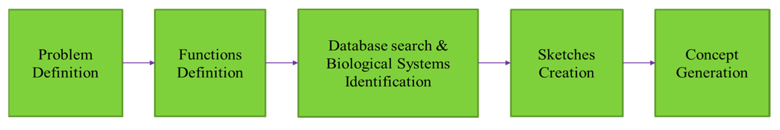
The bioinspired design process depicted in
Figure 1 was used in this research. The first step in the process is Problem Definition, which describes the purpose of the design. In this work, the problem is defined as designing a 3D printing infill pattern that uses less material and has the same or better mechanical properties as current infill patterns. The second step is Functions Definition, which is when the problem is reframed as a set of functions the design should achieve. In this work, the three major functions are lightweight, load resistant, and resilient under compressive environments. These functions are selected because of their comparability with parts that are manufactured using other approaches. Measuring the load resistance and resiliency of the material structures in comparison with the weight affords analysis of strength-to-weight values.
Step three is Database Search and Biological Systems Identification. During this step, inspiring biological systems were found using keyword searches that matched the set of desired functions. In this work, three biological systems were selected for the comparative study and are a bird nest structure, a cocoon structure, and a sandwich structure as shown in
Figure 2. These were selected due to their prevalence in nature, as well as previous research investigating similar bioinspired structures.
The Sketches Creation step involves hand drawing ideas whereas the final step of Concept Generation involves transitioning the sketches into 3D design platforms such as AutoCAD’s Fusion 360 V.2.0.15050 [
29] or nTop [
30]. In this work, nTop was used for concept generation. nTop can be used for multiple design tasks including generative design, simulation, and topology optimization. This software was selected because it contained the necessary infill patterns that were needed for the comparative study.
2.1. Bioinspired Structures
The first infill pattern structure that was designed was the bird nest structure. As the name suggests this design is inspired by a bird’s nest and consists of intertwining branch-like beams. Beams shape are the structures shaped by the beams inside the part. Each beam is characterized by its length, angle, connectivity, and thickness. The connection of beams forms the bioinspired infill structures in this study. This design meets the functional objectives because the max load is spread across the branch-like beams while reducing weight. Three variables for the bird nest-inspired infill pattern that were tested are the beam shape, thickness, and edge length. The second infill pattern structure designed was the cocoon structure, which is designed to house two different structures in one. This design is inspired by the cocoon’s rigid inner structure and a more flexible outer structure. The inner structure provides vertical support for the cylinder and the two-structure shape reduces material use and weight. The inner pattern and outer pattern can be designed with different densities and beam shapes. It meets the functional objectives because the max load is spread across the flexible outer layer (similar to a bird nest) while reducing weight. Two variables for the cocoon-inspired infill pattern that were tested were the inner layer pattern and outer layer pattern.
The third infill pattern structure is the sandwich structure, and is inspired by the alternating hard/compact and soft/porous layers of biological systems such as trees, turtle shells and skulls. The typical orientation of these layers is the soft/porous layer between hard/compact layers. The design consists of multiple layers of alternating fill densities and meets the functional objectives because the max load is spread across many material layers while reducing weight. Three variables for the bone-inspired infill pattern that were tested were the number of layers, the orientation, and the type of infill pattern that was used.
The cylinders were designed with solid outside layers with a top, bottom, and side. The size of the cylinders was originally 25.4 mm tall with a diameter of 12.7 mm to follow ASTM D695-15 which is the standard for measuring the Compressive Properties of Rigid Plastics [
31]. The 3D models in
Figure 2 show what the bioinspired structures look like in nTop. In this study, an experimental lab test was applied instead of using finite element analysis (FEA) because there is a standard test environment and all the tests can be conducted in the lab with the equipment available. The results from these tests also allow comparison with other similar studies. Due to print complexity and failures, the 3D-printed parts were scaled 300%. Each design had multiple variables that were altered to understand how the different combinations of the variables and the relationship between them affect strength and resiliency while considering weight.
2.2. Experiment Design
For the bird nest-inspired infill structure, a total of 24 specimens were fabricated to test for the influence of the three variables.
Table 1 outlines how the beam shape, thickness, and edge length were changed for each of the designs. The bean shapes were selected from commonly available 3D printing infill patterns.
The cocoon-inspired infill structure design consists of nine different specimens with two variables as shown in
Table 2. The inner cylinder pattern and the outer cylinder pattern were selected from commonly available 3D printing infill patterns.
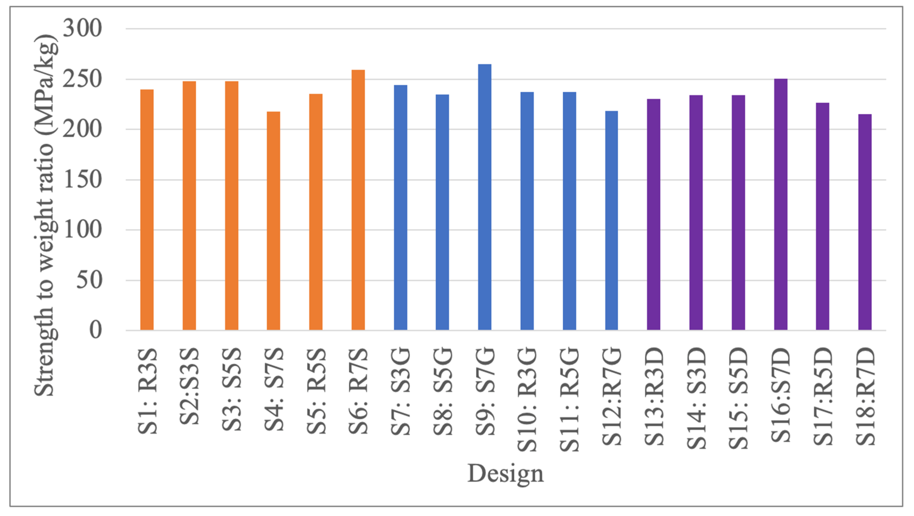
For the sandwich-inspired infill structure, a total of 18 specimens were fabricated to test for the influence of the three variables.
Table 3 outlines how the orientation, number of layers, and infill patterns varied for each of the designs. A standard orientation refers to the design having the same layering as natural systems with harder layers on the outside and softer layers on the inside. A reverse orientation is the opposite with softer layers on the outside and harder layers on the inside. As the number of layers increases, the alternation continues. For example, design S8: S5G has the following structure from top to bottom: fully dense layer, Gyroid layer, fully dense layer, Gyroid layer, and fully dense layer. The infill patterns were selected from those commonly available for 3D printing.
A control group was also included in the study. Three control group designs were fabricated using the commonly available line infill pattern at three different fill percentages (40%, 60%, and 80%). No other variables were changed.
2.3. Printing Parameters and Material
For this study, we 3D printed all designs using a Dremel Digilab 3D printer using the parameters in
Table 4.
The material used in the experiment was Polylactic Acid (PLA) which is made from organic and renewable resources such as corn starch, tapioca roots or sugar cane. It is one of the common 3D printing materials.
2.4. Experimental Setup
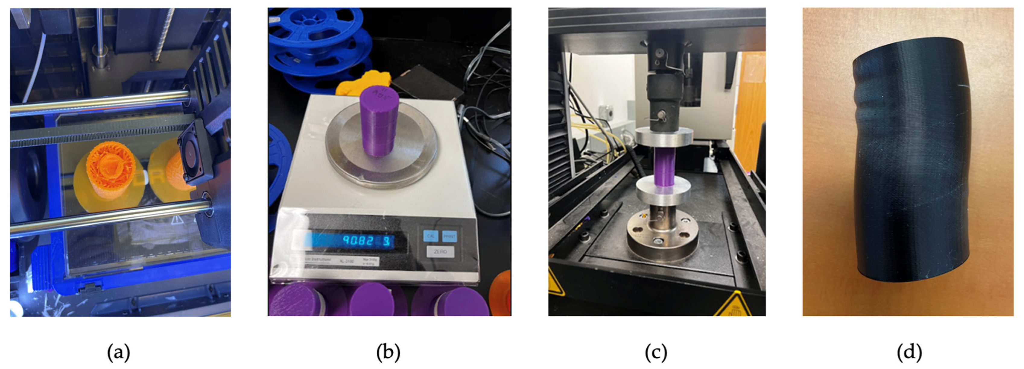
Each design was printed and then weighed before destructive testing as shown in
Figure 3. Compression tests of all specimens were conducted with an Instron machine that has a maximum load of 30,000 Newtons. However, to protect the machine, the maximum loading was limited to 25,000 Newtons. The rate of load was 40% and the extension was 60 mm.
3. Results and Analysis
This study aims to understand the functions of lightweight, load resistant, and resilient bioinspired infill structures. The following equations were used to analyze the data collected against the functional objectives. The first equation is used to determine strength to weight ratio and compares the weight of the specimen to the amount of weight it can support without collapsing, or the peak load value as determined from the compression test. The equation for the strength-to-weight ratio is
The second equation is used to determine the resilience of the design. Resiliency can be described as the ability of a part to absorb energy during elastic deformation, or simply the ability of an object to spring back into shape. The resilience equation is
where
σy = yield strength and
εy = yield strain. It is calculated by multiplying the yield strength and strain values for a specimen as collected from the compression test and dividing by two.
3.1. Results Summary of the Designs
This section provides the results and analysis of the study to show how all the designs compared to each other.
Table 5 lists the data collected and used for the analysis and
Figure 4,
Figure 5 and
Figure 6 provide comparative plots of all the designs. The full experiment result dataset can be found in
Appendix A.
As shown in
Figure 4, the sandwich-inspired structures perform similarly but also reach the maximum load limit on the Instron machine. The cocoon and bird nest-inspired structures perform similarly, except for the four outlier bird nest structures. The control group structure at 40% is similar to the cocoon and bird nest-inspired structures, while the 60% and 80% are similar to the sandwich-inspired structures. Focusing on the relationship between max load and weight, the results show that the sandwich-inspired structures have the highest weights and max loads, whereas the bird nest and cocoon-inspired structures are tightly grouped together at the midway point for loading but are half the weight of the sandwich inspired structures. From this, we learn that there is a positive relationship between the weight of a structure and the maximum load that it can handle. This trend is also evident in the control group.
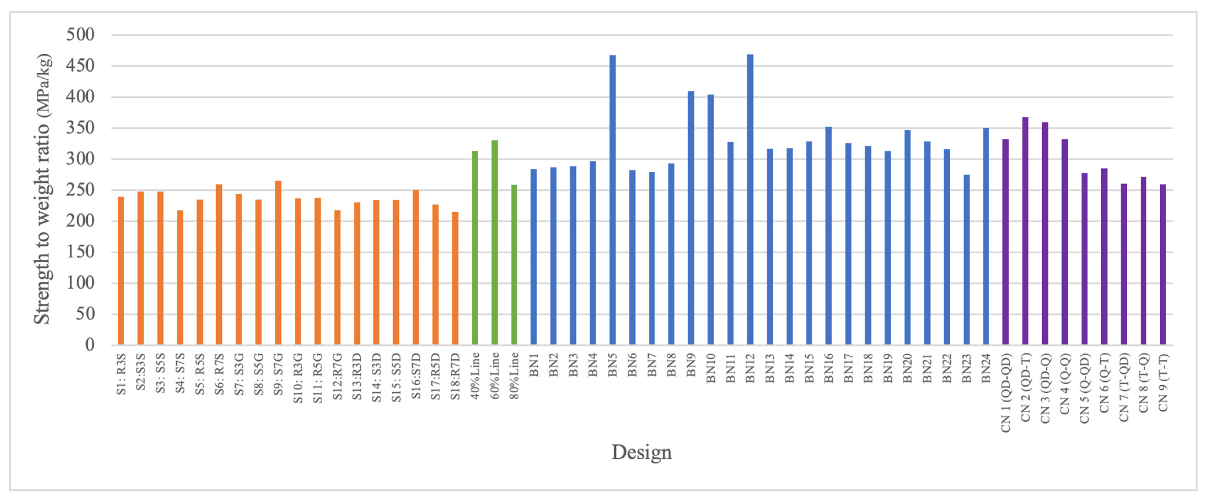
The comparison of strength-to-weight ratios of all the structures is shown in
Figure 5. The sandwich structure is orange, the bird nest is blue, the cocoon is purple, and the control is green. Each bar represents one structure design name which can be found in
Table 5. The sandwich-inspired structures have lower values than the rest due to those structures being heavier than all the other designs. The four outliers in
Figure 4, bird nest-inspired structures 5, 9, 11, and 14, show high performance for strength-to-weight ratio. When comparing the strength-to-weight ratios of all the specimens together, the bird nest and cocoon-inspired structures perform better than the sandwich-inspired structures and similar or better than the control group. Both the bird nest and cocoon-inspired structures have a much lower weight value while having relatively high strength values. We can learn from this that the amount of weight a structure can handle per unit of weight could be a lot higher for lightweight structures, or that strength can be increased while weight is decreased.
Figure 6 shows the calculated resilience of all the tested structures plotted against weight. The sandwich-inspired structures demonstrate higher resilience than the bird nest and cocoon-inspired structures but also higher weight. The reasoning for this result is that the sandwich-inspired structures have more solid layers internally compared to the bird nest and cocoon structures. Thus, it is expected that their resiliency will be higher due to having a higher elasticity. We learn that for a lighter specimen, some of the resilience is sacrificed due to less material and weight being present. The bioinspired structures seem to follow a linear relationship; however, the control group seems to follow a parabolic relationship with 60% having the highest resilience.
3.2. Bird Nest
Analysis of the bird nest-inspired infill structures started with the weight-to-max-load ratio. This relationship reveals outliers in
Figure 7. For example, at roughly 45 g, BN5 and BN12 show higher max load results in comparison to those that follow the trendline of weight to max load. Both are similar in weight but differ in beam shape (triangle vs. quad). We also see that there is a relatively even distribution across
Figure 7 for the triangle and quad beam shapes. Thus, for max load, the variables of thickness and edge length have a greater impact on the performance.
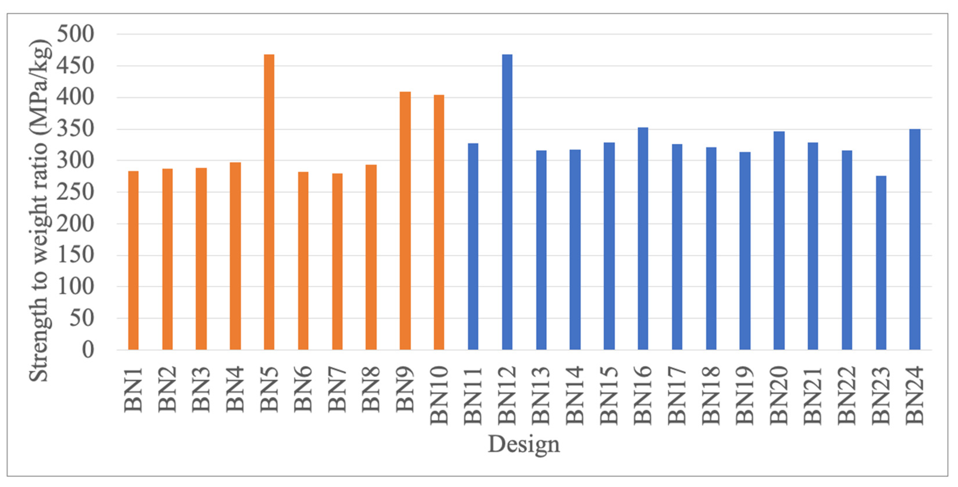
The strength-to-weight ratio analysis for the bird nest-inspired structures is shown in
Figure 8. The same color coding of
Figure 7 is used to distinguish between the beam shape is used. Orange represents a triangle, while blue represents a quad. The results indicate that structures with a quad beam shape have a slightly higher strength-to-weight ratio, but that they are all relatively close in value. The two outliers of BN5 and BN12 as seen in
Figure 7, also appear in
Figure 8. BN5 has a triangle beam shape of 0.3 mm thickness and BN12 has a quad beam shape of 0.3 mm thickness and smaller edge lengths, which makes them nearly equal in weight but close to the average weight across all the specimens. Overall, the bird nest-inspired structures had relatively equal strength-to-weight ratios, and this is due to the lightweight design.
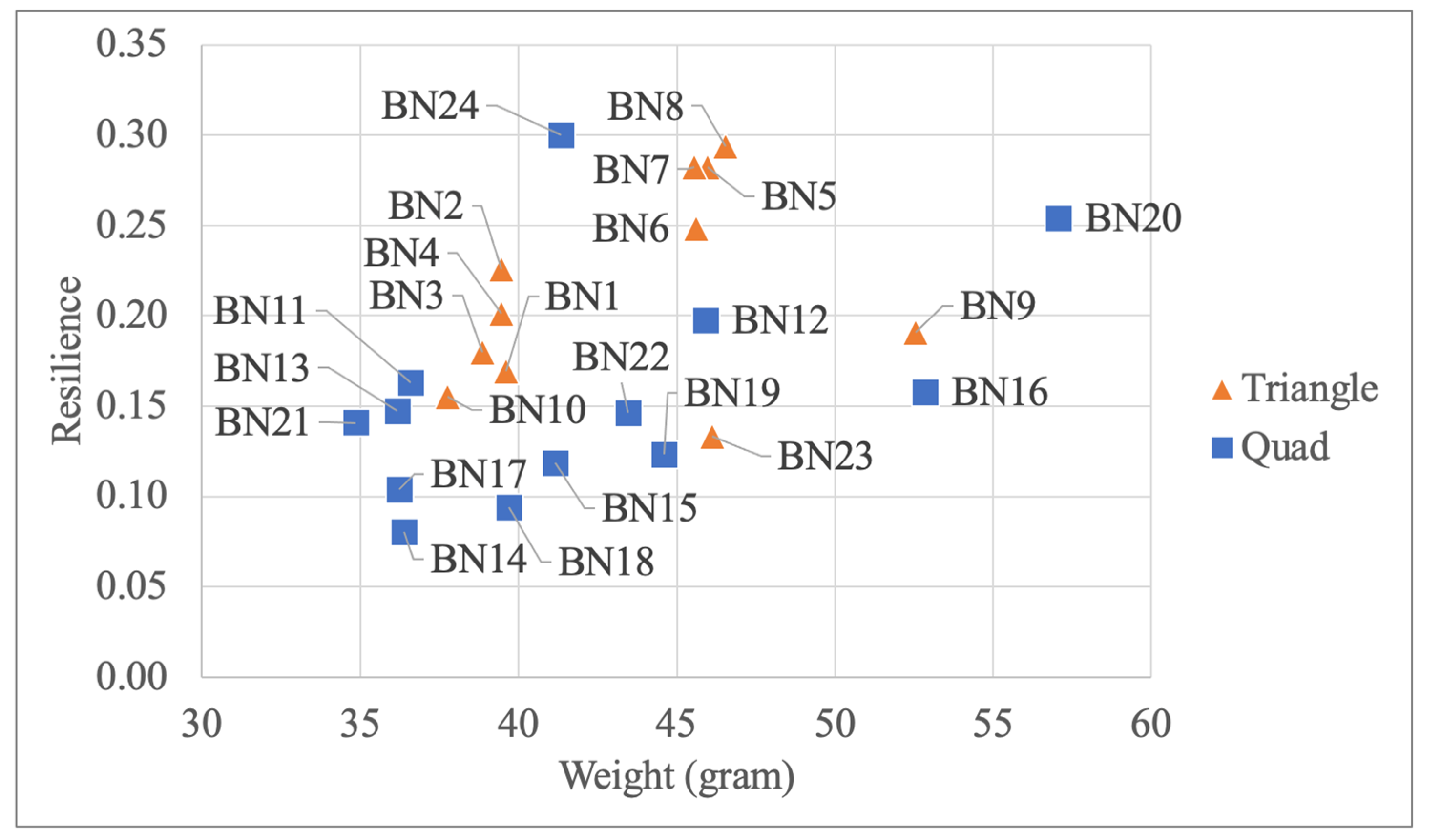
Figure 9 shows the weight vs. resilience analysis for the bird nest-inspired structures. The same color coding and shapes used in
Figure 7 to distinguish between the two beam shapes are also used. Again, we see a relatively even distribution for the two beam shapes. However, the spread of the quad beam shape specimens is wider. Clustering of the results for the triangle beam shape is directly related to the beam thickness with smaller on the left (lighter) and larger on the right (heavier). The middle thickness of 0.4 mm shows the highest resilience for the triangle beam shape.
Overall, the bird nest-inspired infill structure data analysis provides multiple insights based on the variables that were changed for the design. When considering which beam shape provides a greater relationship for strength, load, and resilience, the triangular shape provides better results as it provides more branching connections in the lattice. A greater number of connections between branches provides more direct support from the bottom and center of the design which makes it stronger, whereas the quad beam shape has fewer branching connections which reduces strength and is higher in mass. The variable of beam thickness demonstrated that higher thickness provides greater strength and resilience to the design. It was found that the smaller the value of edge length, the better the performance. This was evident for the outstanding outliers in the data collection.
3.3. Cocoon
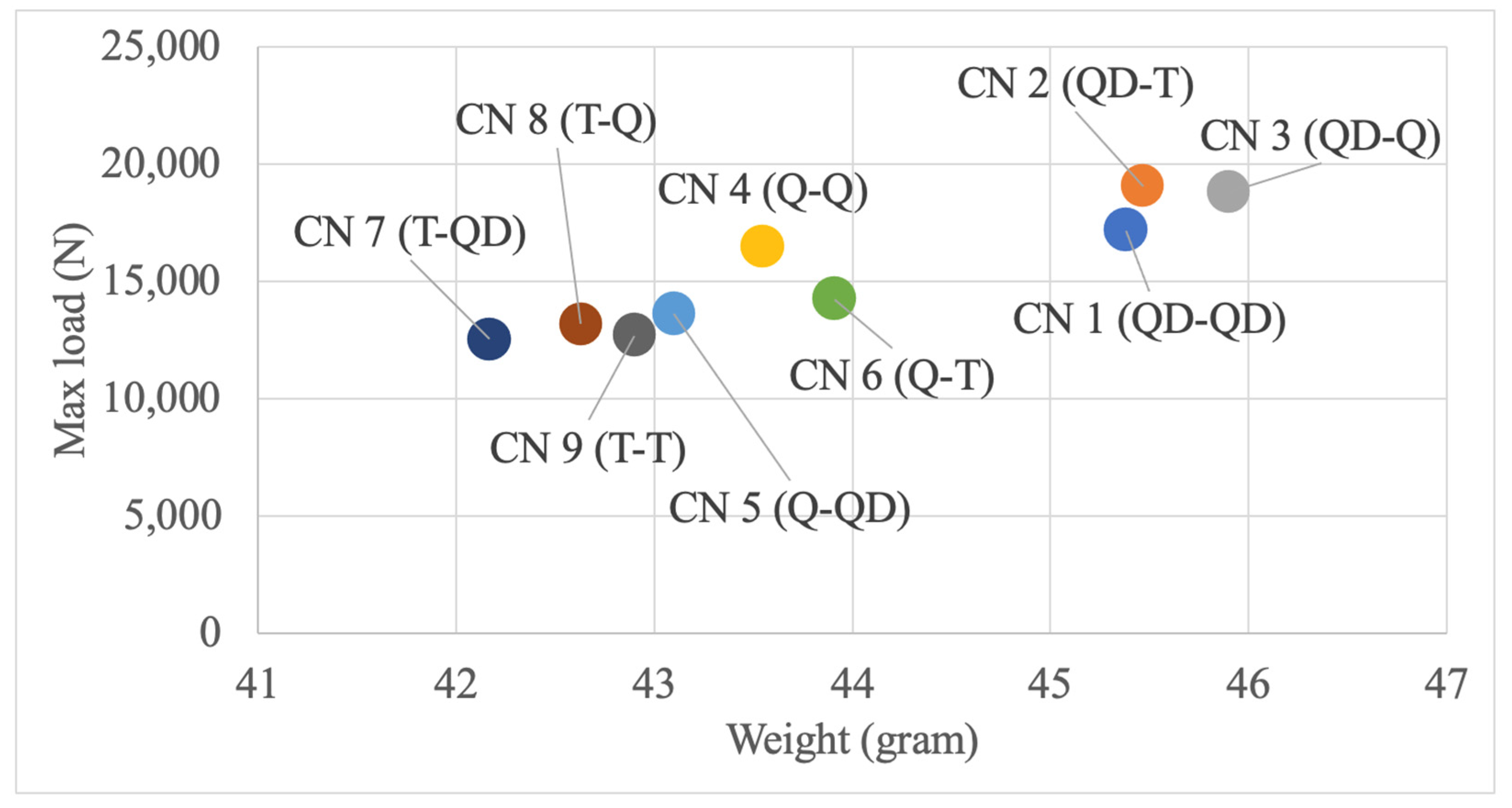
Analysis of the maximum load-to-weight relationship reveals a gap between the Quad–Dominant inner pattern specimens and the rest of the specimens as shown in
Figure 10. These specimens have the highest weight of all the cocoon-inspired infill structures as listed in
Table 5. Of the lighter cocoon-inspired structures, the CN 4 (Q-Q) design which has Quad inner and outer patterns (not Quad–Dominate) has a relatively high maximum load while having a lower weight, respectively.
The strength-to-weight ratio analysis for the cocoon-inspired structures is shown in
Figure 11 and uses the same color coding as
Figure 10. A similar trend to the weight and maximum load relationship is seen for the strength-to-weight ratio. The Quad–Dom structures have the largest strength-to-weight ratio followed by the Quad–Quad structure. Although the Quad–Dom structures have a higher weight, they allow for more connections between the inner and outer structures which increases the overall strength. We learn that having a solid connection between the inner and outer layers is a key aspect that affects the strength of the specimen.
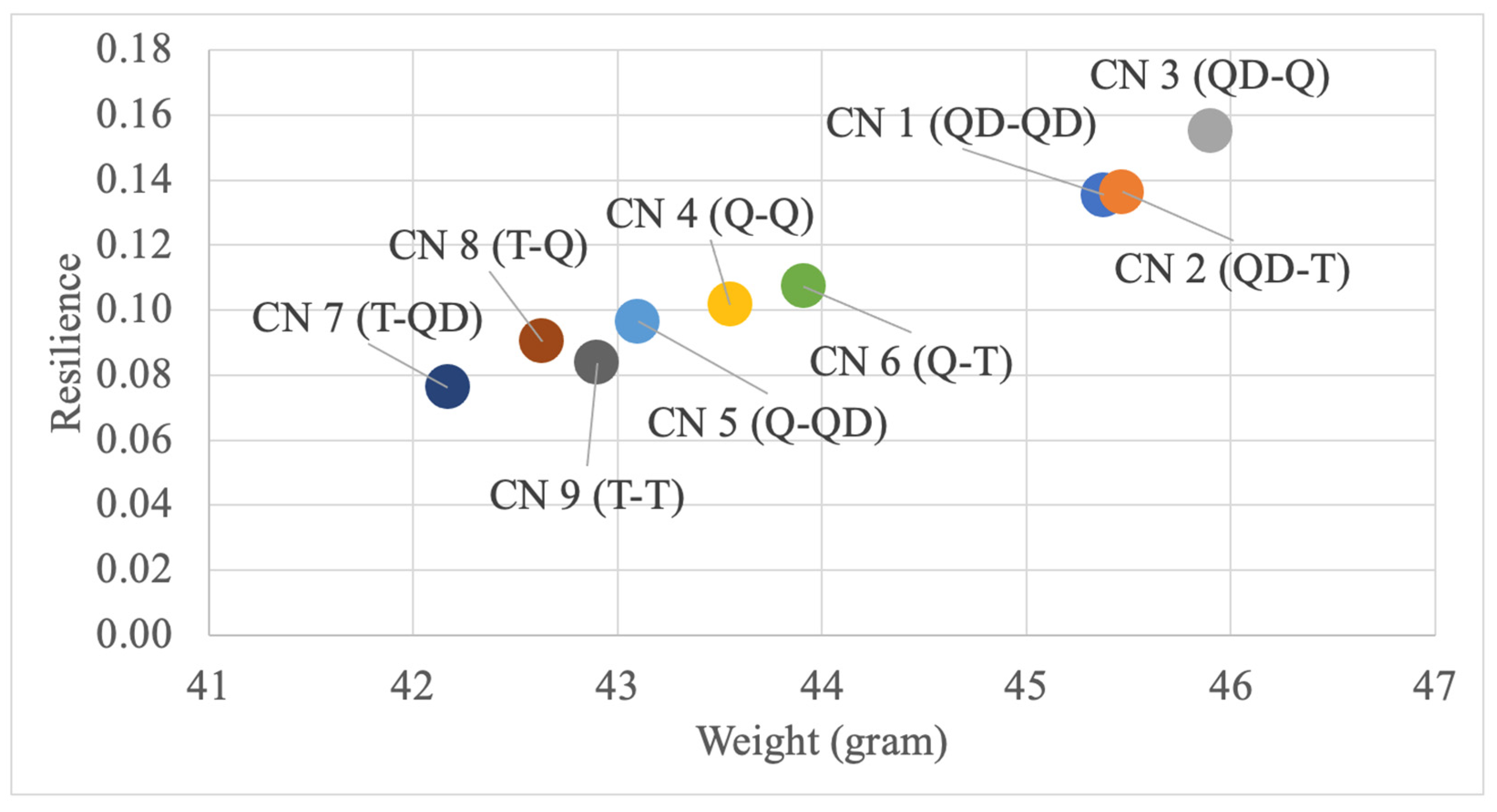
Figure 12 shows the weight vs. resilience analysis for the cocoon-inspired structures, and uses the same color coding as
Figure 10. Analysis of resilience again shows a gap between the Quad–Dominant inner structures and the rest of the specimens. The structure with the highest resiliency factor was the CN 3 (QD-Q) specimen, and the structure with the worst resiliency factor was the CN 7 (T-QD) structure. These results are not as surprising given the fact that the overall weight of the cocoon structures is relatively low compared to some of the other bioinspired infill structures designed.
Overall, the cocoon-inspired infill structure data analysis provides some insights based on the two variables that were changed for the design. A key aspect of the design is that the shape of the layers and how the layers form connections affect the max load and yield strength. This is shown throughout the data by the Quad–Dominate infill patterns having higher strength and max load values. Another key finding is that using two vertical layers (inner and outer) leads to an increase in the strength values, with a partial increase in the weight value. This is seen when comparing the data from the cocoon-inspired structures to the bird nest-inspired structures.
3.4. Sandwich
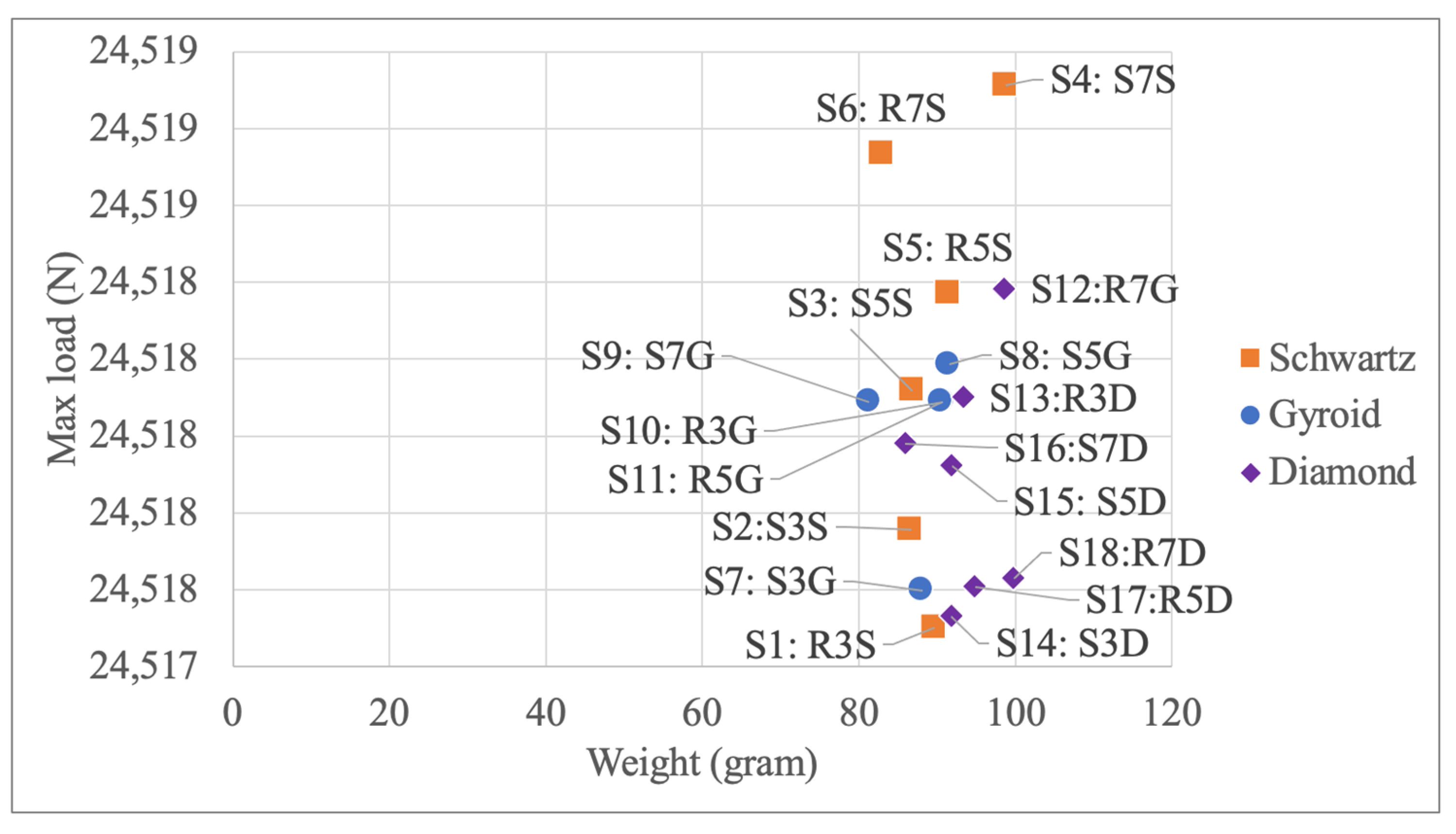
As shown in
Figure 13, analysis of the sandwich-inspired infill structures’ weight-to-max load ratio indicates that almost every single specimen performed similarly. All the sandwich-inspired structures were very close to the maximum load limit of the testing machine; thus, we were not able to figure out an exact value for each due to machine constraints. The high max load capability is due to high weight and good connections between layers. We learn that there is a positive relationship between the weight of a specimen and the maximum load it can withstand.
The strength-to-weight ratio analysis for the sandwich-inspired structures is shown in
Figure 14 and uses the same color coding as
Figure 13. This analysis indicates that the structures with the highest and lowest ratios also had the highest number of layers across all infill pattern types. The Schwartz infill pattern structures on average had the best strength-to-weight ratio; however, the ratios of all the specimens have relatively similar values. Because each sandwich-inspired structure had similar max and yield loads, the only variable that affected the performance was the weight. We learn that withstanding a higher maximum load does not mean greater performance on a unit basis.
Figure 15 shows the resilience-to-weight relationship of the sandwich-inspired infill structures. Again, the highest-performing designs were those with the Schwartz infill pattern as well as a standard orientation. The Gyroid and diamond infill pattern structures showed the most consistency.
Analysis of the sandwich-inspired infill structures reveals a key trade-off. The higher number of layers increases strength but also weight. The Schwartz infill pattern outperformed the Gyroid and diamond patterns in resilience and strength-to-weight ratio. In contrast, the diamond infill pattern performed the worst of the three. Changing the orientation increases the material resiliency. We see that the infill pattern variable has the highest influence on meeting the functional objectives for the sandwich-inspired infill structure.
4. Discussion
The results of this study provide insights into the functional performance of the designed bioinspired infill structures. Notably, the data reveal that sandwich-inspired structures exhibit a direct correlation between weight and maximum load-bearing capacity, underscoring the adage that strength often comes at the expense of increased mass. However, this trend does not hold uniformly across all designs. Bird nest and cocoon-inspired structures present an intriguing anomaly wherein they maintain considerable strength while significantly reducing weight, challenging traditional design paradigms that equate mass with capacity. Specifically, these lightweight designs demonstrate a favorable strength-to-weight ratio, indicating that strategic design can indeed lead to material efficiency without compromising structural integrity.
The resilience measurements further delineate the trade-offs inherent in material distribution within the structures. Sandwich-inspired structures offer superior resilience, likely attributable to their increased mass and internal solid layers, which facilitate elastic deformation and energy absorption. In contrast, while bird nest and cocoon-inspired structures exhibit lower resilience, this is compensated by their reduced weight and efficient load distribution, which is a critical consideration for applications where weight is a limiting factor such as aerospace components and wearable technology.
The outliers identified, particularly within the bird nest-inspired structures, highlight the impact of geometric variations on the performance metrics. The superior performance of these outliers suggests that specific design variables, such as beam thickness and edge length, can significantly enhance structural performance. This finding advocates for a more nuanced approach to infill design, moving beyond a one-size-fits-all strategy to a tailored optimization that accounts for the unique demands of each application. Thus, the findings of this study are as follows:
Not one bioinspired infill structure excelled at all three functional objectives—lightweight, load resistant, and resilient under compressive environment;
Structures inspired by sandwiched bone layers excel in resilience and peak load resistance;
Structures inspired by bird nests and cocoons excel in being lightweight;
Bird nest-inspired structures exhibited the highest strength-to-weight ratio, which shows the potential for meeting multiple functional objectives;
The performance of the bioinspired infill structures is sensitive to the unique variables associated with each design (e.g., beam thickness, edge length) and could be tailored to the needs of an application.
In summary, the study’s findings advocate for a paradigm shift in infill design, with a move towards structures that leverage the inherent geometrical strengths of bioinspired patterns to achieve both lightness and load-bearing capability. The implication of this research is clear: through intelligent design inspired by nature, it is possible to create structures that defy traditional weight–strength trade-offs, paving the way for innovative applications in fields demanding high-strength, lightweight materials.
5. Conclusions
In this study, the experimentally measured values of mechanical properties of 3D-printed specimens (cylinders) produced using a desktop 3D printer were presented. These specimens were printed in PLA using the Fused Deposition Molding method and tested following the ASTM D695-15 standard. The performance of the specimens across three functional objectives—maximal supported load in compression, resiliency, and strength-to-weight ratio—was analyzed. Three bioinspired infill structures were designed using inspiration from a bird nest, a cocoon, and the sandwiched alternating hard and soft layers found in trees, turtle shells, and bone. For comparison, a control group of three specimens using the commonly available line infill pattern was fabricated and tested.
A limitation of this study is that the curved geometries found in nature for the bird nest, cocoon, and skull bone were adapted to a small, cylindrical shape to meet the ASTM D695-15 testing standard. A turtle shell and skull are closer in geometry to a sphere than a cylinder and may be lighter and perform better than the engineered infill patterns if the geometry and testing conditions were different. Bird nests, cocoons, and porous layers of bone are not perfectly repeated cellular units; rather, they have variance and imperfections. Thus, the CAD software limits how the bioinspired design is embodied.
Strength, weight, and resilience were compared to each other and a control group for the three different bioinspired designs. However, when it comes to real-world applications more research must be carried out in order to bring this work into engineering practice. Thus, future research would involve replicating all the specimens and tests multiple times to achieve an average value for each design but also calculate descriptive statistics. This would also assist with determining design attributes that could be explored in more detail. Additional future work involves developing and executing a procedure to test different geometries that are closer to the biological geometries.
This work demonstrates the effectiveness and limitations of three bioinspired designs to achieve lightweight, strong, and resilient additively manufactured parts. We believe the findings of this study contribute to the expansion of bioinspired design applied in the area of additive manufacturing.


