Article

Nonlinear Identification and Decoupling Sliding Mode Control of Macro-Micro Dual-Drive Motion Platform with Mechanical Backlash

Ji Hua Laboratory, No.28 Huandao South Road, Guicheng Street, Nanhai District, Foshan 528200, China
*
Author to whom correspondence should be addressed.
Machines 2023, 11(12), 1044; https://doi.org/10.3390/machines11121044
Submission received: 9 October 2023 / Revised: 8 November 2023 / Accepted: 15 November 2023 / Published: 23 November 2023
(This article belongs to the Section Automation and Control Systems)

Abstract

:
A macro–micro dual-drive motion platform is a class of key system utilized in ultra-precision instruments and equipment for realizing ultra-high-precision positioning, which relates to the fields of semiconductor manufacturing, ultra-precision testing and machining, etc. Aiming at the ultra-high-precision positioning control problem of macro–micro dual-drive systems containing mechanical backlash, this paper analyzes the combined effect of mechanical coupling and backlash, and proposes a macro–micro compound control strategy. Firstly, the system dynamic model, including mechanical coupling, is established, and a quasi-linear backlash model is also proposed. Secondly, based on the above model, a stepwise nonlinear identification method is proposed to obtain the backlash characteristic online, which is the basis of accurate backlash compensation. Then, for the macro–micro structure containing the backlash, a macro decoupling control method, combined with a micro adaptive integral sliding mode control method and backlash compensation, are designed coordinately to guarantee that the large-stroke macro–micro cooperative motion reaches micron-level accuracy. Moreover, the boundary of the positioning error is adjustable by tuning the controller parameters. Finally, both the simulation and experimental results demonstrate that the proposed identification method can estimate the time-varying backlash precisely in finite time, and the system positioning accuracy can achieve an average 20 μm with long stroke and backlash influence, which is much higher than that using the traditional method and provides theoretical guidance for high-precision positioning control of a class of dual-drive motion platform.

1. Introduction

The precision motion platform, widely applied in the fields of semiconductor manufacturing, ultra-precision testing and machining, etc., is one of the key subsystems for high-end equipment, such as mask aligners, OLED/Micro-LED display printers and chip super-resolution detection manipulators, to achieve large-stroke micron/nanoscale precision positioning. For this kind of platform, a macro–micro structure is generally adopted to realize a multi-stage mechanical drive, which is designed to connect directly or in bridge-type form. Utilizing cooperative control on the above structure can help equipment reach the industrial requirement of micro–nano high-accuracy positioning under large-stroke movement.
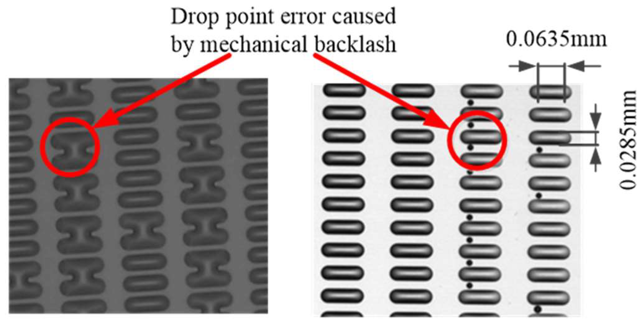
Due to the backlash phenomenon that generally exists in mechanical connections, self-excited oscillation may finally occur when its energy accumulates to a certain extent from the relative motion between different mechanisms. In addition, long-term wear in the joints of mechanisms will gradually increase the backlash, then aggravate the self-excited oscillation and eventually cause a state of instability, which greatly deteriorates the positioning-control performance of mechanical systems [1]. Specifically, in the field of OLED/micro-LED display printing, more special requirements have been raised for the printing process concerning the precision and stability of the above-mentioned macro–micro motion platforms. An OLED/micro-LED display inkjet printer under manufacture working conditions usually needs to work continuously for several months or much longer without readjustment, and it injects huge amount of ink droplets into the designated pixel slots at high speeds without online visual observation feedback. Considering that the impact position of each ink drop always shows randomness within a certain range and film formation defects cannot be repaired after printing, the positioning bias between the print head nozzle and designated pixel slot caused by mechanical backlash, and the random impact position deviation of ink drops, will jointly produce an obvious influence on the printing precision, which directly degrades the quality of wet film forming and also the final product. For example, when printing using the OLED inkjet equipment shown in Figure 1, due to the inaccurate positioning influence caused by backlash, several ink drops landed outside of their corresponding pixel slots, forming liquid bridges or scatters (shown in Figure 2), which will cause the displayer to glow abnormally.
Given that the impact position deviation of ink drop is relatively small compared to the backlash-caused bias, and the backlash generated from initial installation, midway maintenance or component wear is generally inevitable in practice, it may lead to massive disqualification of OLED products and time/financial losses once tiny backlashes can be detected long after manufacture starts. Therefore, it is highly necessary to analyze and compensate for this backlash characteristic in the control design process, as the last defense line for ensuring the equipment’s accuracy, robustness and final production quality. In Ref. [2], the Nyquist method was applied to analyze under what working conditions the limit-cycle phenomenon will be excited by backlash. In Ref. [3], a general hysteresis model in the form of a piecewise function was established to represent backlash, and then a multi-step model predictive compensator for discontinuous systems was proposed to suppress its effect. Ref. [4] focused on analyzing the influence of valve backlash on hydraulic manipulator dynamics and designing a robust compensator via the back-stepping method. Considering the strong coupling between multi-axes, modeling and experimental analysis on the coupling characteristics through backlash in a macro–micro positioning system based on a planar parallel structure has been carried out in Ref. [5]. Furthermore, taking coupling, backlash effect and uncertain disturbances into account, a global iterative sliding mode control method was proposed to adaptively compensate for the matched unknown dynamics and suppress chattering by varying gains [6]. In addition, an extended set-membership filter-based observer was designed to estimate the backlash influence for a robotic flexible ureteroscope system [7]. On the basis of time-delay estimation for observing the comprehensive effect of backlash and external disturbance, a self-tuning robust controller was constructed to enhance the motion performance of robotic manipulators [8].
In addition to considering the influence of mechanical backlash, a corresponding control strategy based on a macro–micro structure will determine the dynamic performance of the whole system. At present, the commonly used control structure is to employ double closed-loop feedback on the macro/micro parts, respectively, so as to realize overall stability and accurate positioning through the cooperative actions of different parts in a platform [9,10]. In terms of control strategy design, the traditional double-loop PID control and its extended methods have been widely used in this kind of motion platform due to its advantages, e.g., no need for modeling, simple design, fewer control parameters and easy adjustment, etc., and it can generally help systems achieve the specified motion accuracy under no-disturbance working conditions [11,12,13]. The control strategies based on frequency-domain analysis could suppress various coupling vibrations by expanding the system bandwidth, which optimizes the dynamic characteristics of platforms [14,15,16]. Nowadays, various modern control strategies, such as predictive control, sliding mode control, internal model control and active disturbance rejection control, have also been gradually applied in such platforms to comprehensively improve both their dynamic performance and positioning accuracy from the angles of convex optimization, nonlinear feedforward and disturbance robustness enhancement [17,18,19,20]. Moreover, adopting the double-input single-output (DISO) control method can avoid the influence of errors introduced by mechanical assembly or an accuracy gap between sensors, and reflects a certain increase in the motion accuracy [21,22,23].
Based on the above literature review, existing work has already discussed the backlash characteristic in transmission mechanisms and its corresponding compensation methods, providing inspiring research directions. Several high-precision positioning control strategies for macro–micro dual-drive systems have also been proposed, which can effectively promote the system tracking performance from both the control structure and the algorithm levels. However, there is still no suitable identification method for obtaining micro-backlash parameters online that has been applied to the above macro–micro dual-drive motion system so far. Thus, it is unable to analyze the influence of time-varying backlash on the macro–micro coupling state and the positioning accuracy in real time, and it cannot even make accurate compensations. Furthermore, during operation, the platform performance may be affected by several factors, including backlash, the macro–micro coupling effect, environmental disturbance, etc., but current control strategies have not fully considered those factors, nor have they studied a class of macro–micro motion platforms with large stroke (more than 0.6 m). Hence, using existing control strategies is not adequate for such platforms to achieve the required positioning accuracy of OLED/Micro-LED display printing, which may ultimately lead to the disqualification of wet film formation.
In order to achieve a good film-forming quality, aiming at a class of large-stroke macro–micro dual-drive motion platform applied in OLED/Micro-LED display printers, the dynamic model of macro–micro dual-drive motion system, including mechanical micro-backlash, is first established in Section 2 for analyzing the influence of backlash associated with mechanical coupling. In Section 3, a stepwise nonlinear identification method is proposed as the basis of accurate backlash compensation, which is designed to estimate the backlash parameters online through state observation. Then, considering the combined influence of backlash, mechanical coupling and external disturbance, a decoupling sliding mode compound control strategy (DSMC) is proposed to realize both strong robustness and micron-precision positioning of a long-stroke macro–micro motion platform (Section 4). In Section 5, an illustrative simulation example and overall performance comparison under traditional PID and proposed DSMC control strategies are discussed. Lastly, the corresponding experimental results are provided in Section 6 for further verification.

2. Dynamic Modeling of Macro–Micro Dual-Drive Motion Platform and Control Problem Formulation

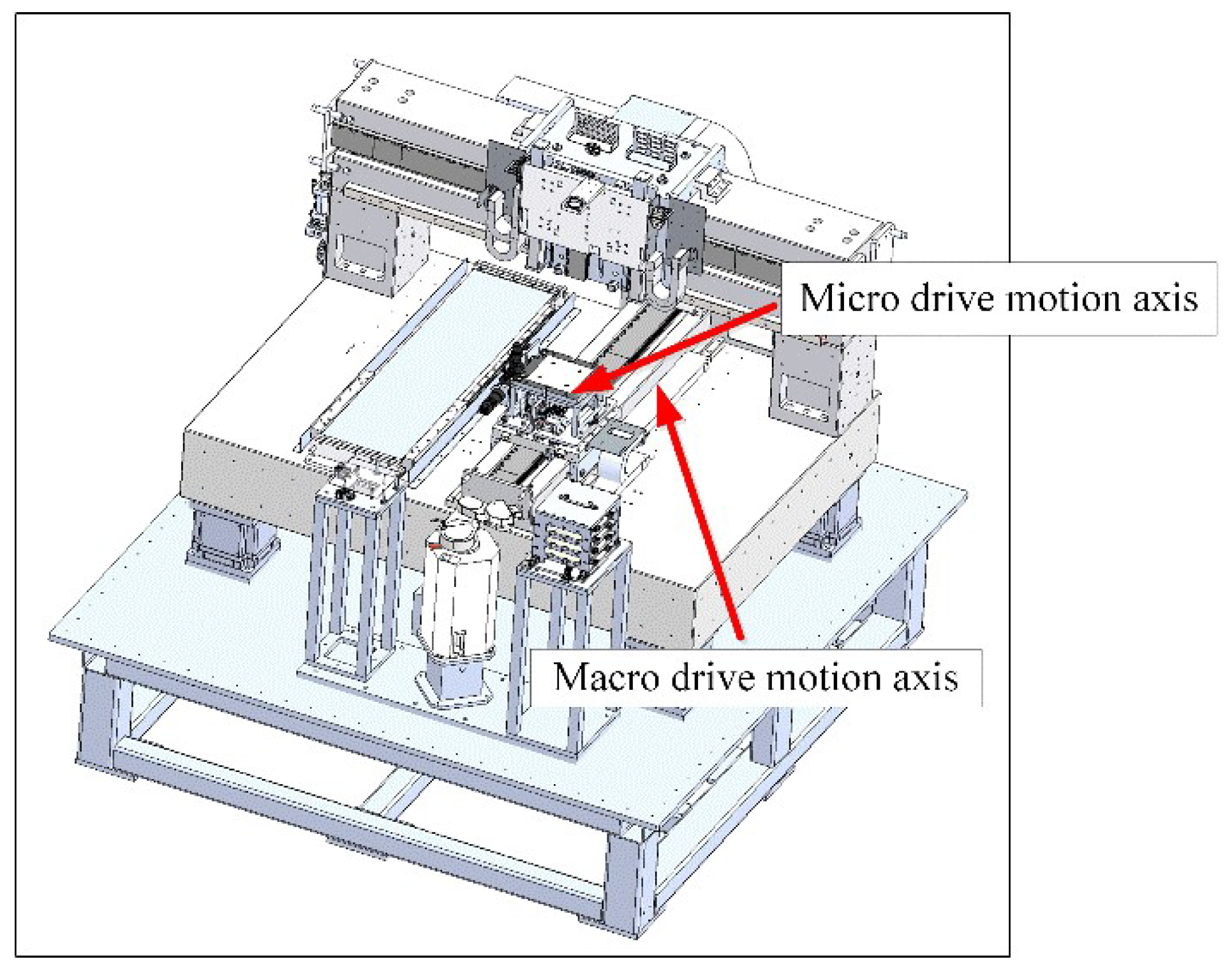
The macro–micro dual-drive motion platform currently applied in OLED/Micro-LED equipment is mainly composed of a macro mechanism series connected with a micro mechanism, where its macro mechanism is designed to ensure the large-stroke motion-positioning accuracy at micron level, and its micro mechanism makes further compensation based on the coarse positioning. The macro and micro mechanisms are actuated by a linear motor and voice coil motor, respectively, and their positions are both measured via laser interferometer. Since the platform adopts the air floating form, friction influence will not be considered. Figure 3 shows the mechanical structure diagram of the macro–micro dual-drive motion platform.

2.1. Description of Macro–Micro Dual-Drive Motion Platform

Based on the designed mechanical structure above, the schematic diagram of the macro–micro dual-drive motion platform is shown in Figure 4.
In Figure 4, m 1 and m 2 are the equivalent mass of the macro and micro mechanism, respectively; b indicates the backlash between macro and micro mechanisms. The equivalent connection stiffness and damping coefficient between the macro mechanism and the base are expressed by K 1 and b 1 respectively, while the equivalent load stiffness and damping coefficient of the micro mechanism are respectively represented by K 2 and b 2 . K l and K r are the equivalent elastic coefficients of the connection between the backlash and the macro/micro mechanism, respectively. Here, the macro mechanism and the micro mechanism are series-connected with a backlash inbetween, which constitute the dynamics of a dual-drive motion platform. The electromagnetic driving force generated by macro and micro actuators are defined as F d r 1 and F d r 2 , respectively. d 1 and d are, respectively, the macro displacement and the total displacement of the platform (that is, the displacement of the end of the micro mechanism) relative to O point under the above driving forces. Since the absolute displacements of macro and micro mechanisms can be respectively expressed as d 1 and d d 1 + b considering the backlash effect, their corresponding force balance equations can be written as follows
m 1 d ¨ 1 + K 1 d 1 + b 1 d ˙ 1 + F b = F d r 1
m 2 d ¨ + K 2 d + b 2 d ˙ F b m 2 d ¨ 1 b ¨ + K 2 d 1 b + b 2 d ˙ 1 b ˙ = F d r 2
where F b K l , b , d , d 1 and its reaction force F b K r , b , d , d 1 are the actual load forces transmitted from the mechanical backlash acting on the macro and micro mechanism, respectively, relating to the relative displacement, backlash width and the equivalent elastic force between the macro and micro mechanisms. Secondly, given that the voltage balance equation and the output force equation of the macro/micro mechanisms’ driving motors show a similar form, respectively, their general description can be expressed as follows
u c = L d i d t + R i + K e m f d x d t
F d r = K m i
where u c , L , R , i , K e m f , K m represent the armature voltage (control voltage), equivalent inductance, equivalent resistance, armature current, back EMF coefficient and electromagnetic force coefficient of the corresponding driving motor, respectively. Here, we define the above parameters with subscript h to describe the macro linear motor, while those parameters with subscript w are set to describe the micro voice coil motor. x represents the absolute displacement of macro/micro mechanisms, that is, x h = d 1 for the macro mechanism and x w = d d 1 + b for the micro mechanism. Above all, Equations (1)–(4) are the dynamic model of the macro–micro dual-drive motion platform with backlash effect.
It can be observed that the load force terms F b , F b appear in the macro/micro force balance Equations (1) and (2), respectively, under the influence of backlash. Furthermore, the extra force term m 2 d ¨ 1 b ¨ + K 2 d 1 b + b 2 d ˙ 1 b ˙ in Equation (2) is generated from the combined influence of the macro/micro mechanism coupling effect and also backlash, which shows that the positioning accuracy of the platform will be affected greatly by the above influence. Therefore, modeling and analyzing the coupling and backlash effect precisely is the theoretical basis for the following compensation.

2.2. Description of Backlash Characteristic

Backlash is essentially a kind of multi-valued discontinuous nonlinear disturbance, caused by insufficient machining accuracy or assembly errors of mechanical components. It will lead to discontinuity and sudden changes of motion and force transmission, and greatly reduce the accuracy and rapidity of such positioning/motion systems. The influence of the backlash effect acting on the transmitted force is shown in Figure 5.
In Figure 5, the horizontal axis represents the displacement of the mechanism actuator, and the vertical axis represents the transmitted load force, F O indicates the continuous load force curve when without backlash, while F b (also in Equation (1)) depicts the actual load force curve transmitted through backlash. b l , b r represent the left and right backlash widths, respectively, when the platform is at the initial position; thus, the total backlash width satisfies b = b l + b r . Without loss of generality, we consider that b l b r and K l K r . For discontinuous F b , its horizontal segment is defined as I; segments with slope c r and c l are defined as II and III respectively.
It can be seen from Figure 5 that backlash causes the original load force curve F O to shift to the left or right side according to different motion directions, which can be equivalent to introducing a disturbance force in dead-zone form into the macro and micro mechanisms. It can be described as
F b t = K r x b t b r x b t b r 0 b l x b t b r K l x b t + b l x b t b l
where x b t = d d 1 represents the relative displacement between the macro and micro mechanism.
According to Equations (1), (2) and (5), although the backlash does not directly exist in the mechanisms but between them, the discontinuous jump of both actual load force and the additional disturbance force term caused by it can be transmitted to the entire platform through the relative displacement of macro and micro actuators, resulting in the motion-state fluctuation of each actuator, and also reflecting the backlash influence on the mechanical coupling. In addition, since the actual displacement of the micro mechanism is jointly decided by the displacement reference signal and the backlash size, by combining Equations (3)–(5), it can be seen that the speed state ( d x w / d t ) fluctuation of the micro actuator can reversely cause the control current fluctuation of the micro voice coil motor under the influence of the mechanical coupling disturbance, and then lead to the output driving force ( F d r w ) oscillation, which significantly affects the positioning accuracy of the entire platform and may damage the motor further.
In summary, the macro–micro motion platform model, considering backlash (1)–(5), can not only describe the macro and micro motion dynamics’ characteristics in line with the actual working conditions, but also reflect the influence of the backlash on the control performance, which is the basis for designing effective motion control strategies for such kinds of platforms.

2.3. Control Problem Formulation

To realize high-precision positioning for the class of large-stroke macro–micro dual-drive motion platform applied in the OLED/Micro-LED printing field, two main challenges we will deal with in this paper are summarized as follows, based on the above dynamic model (1)–(5):
Mechanical backlash introduces piecewise force into macro and micro mechanisms, which makes it difficult to identify the time-varying width of backlash using common linear methods, and further causes backlash compensation to be less accurate.
Under loading conditions in practice, macro and micro mechanisms are both affected by a discontinuous mechanical coupling effect and external environmental disturbance (e.g., random airflow, base vibration); thus, the high positioning accuracy of the entire motion platform is not easy to achieve.

3. Improved Backlash Model and Nonlinear Identification Method Design

For challenge 1, an improved quasi-linear backlash model is first proposed in this section, which can express the piecewise model (5) in a continuous form. Then, based on the improved model, a corresponding nonlinear identification method is designed to accurately estimate the time-varying backlash characteristic online.

3.1. Quasi-Linear Backlash Model

First, define the backlash state factor as follows
δ b = 0 > 0 1 0
When the decision condition ∗ > 0, the system is in the backlash state, and vice versa. As the signal of the condition changes, the factor outputs 0 or 1, indicating the switch of the system states.
In order to judge the state switch I↔II and I↔III, define the above switch conditions as b r x b t and x b t b l respectively, then Equation (6) can be rewritten as
δ I I I b t = δ I I I b b r x b t δ I I I I b t = δ I I I I b x b t b l
By introducing Equation (7) into Equation (5), the backlash disturbance force can be expressed in the following linear form
F b t = K l x b t δ I I I I b t + K l b l δ I I I I b t + K r x b t δ I I I b t K r b r δ I I I b t
Equation (8) is the improved quasi-linear backlash model based on the dead zone function. For the convenience of identification method design, the backlash state marker h b t is separated from its characteristic parameter θ b thus, Equation (8) can be rewritten as the following form
F b t = h b T t θ b = x b t δ I I I I b t δ I I I I b t x b t δ I I I b t δ I I I b t K l K l b l K r K r b r
As can be seen from Equation (9), when the backlash disturbance force F b t is measurable, the backlash parameters can be obtained via linear identification methods. Therefore, the proposed improved quasi-linear model can effectively solve the identification problem caused by the backlash discontinuity.

3.2. Nonlinear Identification Method Design for Backlash Characteristics

In practice, the disturbance force transmitted through the backlash is usually unknown. Therefore, it is necessary to estimate the value of disturbance force F b t accurately for the further backlash parameter identification. In this section, a stepwise identification method based on nonlinear sliding mode theory is proposed. Firstly, F b t is estimated according to the dynamic model (1)–(5). Then, based on the estimated F b t and quasi-linear model (9), the backlash parameters are identified online.
 A.
Estimation of nonlinear backlash disturbance force
Due to the discontinuity of F b t , a nonlinear observer is designed based on the second-order sliding mode super-twisting theory. It can simultaneously ensure finite-time observation of the displacement and velocity of the macro and micro mechanisms, and then calculate the F b t using the above signals.
The observation is carried out under the following working condition: the macro mechanism is driven to run a micro sine motion, and the micro mechanism is dragged to follow this motion. In this case, the micro mechanism can be regarded as the load of the macro mechanism, and the dynamic equations of the platform under this condition can be written as
m 1 d ¨ 1 + F 1 d 1 , d ˙ 1 + F b = F e s t m 2 d ¨ + F 2 d , d ˙ = F b
where F 1 and F 2 represent the sum of equivalent elastic force and stiffness force of the macro/micro mechanism, respectively, and F e s t is the input driving force of the macro mechanism in the estimation test. Let x 1 h = d 1 , x 2 h = d ˙ 1 , x 1 w = d , x 2 w = d ˙ Equation (10) can be rewritten in state equation form as follows
x ˙ 1 h = x 2 h x ˙ 1 w = x 2 w x ˙ 2 h = F 1 x 1 h , x 2 h m 1 + F e s t m 1 F b m 1 x ˙ 2 w = F 2 x 1 w , x 2 w m 2 + F b m 2
According to Equation (11), the nonlinear observer for macro and micro mechanisms based on a second-order sliding mode super-twisting method is designed as follows
x ^ ˙ 1 h = x ^ 2 h + η 1 x ˜ 1 h 1 / 2 sgn x ˜ 1 h x ^ ˙ 1 w = x ^ 2 w + η 2 x ˜ 1 w 1 / 2 sgn x ˜ 1 w x ^ ˙ 2 h = F 1 x ^ 1 h , x ^ 2 h m 1 + F e s t m 1 + ι 1 sgn x ˜ 1 h x ^ ˙ 2 w = F 2 x ^ 1 w , x ^ 2 w m 2 + ι 2 sgn x ˜ 1 w
where x ^ 1 h and x ^ 1 w are the observed displacement of the macro/micro mechanism, respectively, x ^ 2 h and x ^ 2 w are the observed velocity of the macro/micro mechanism, respectively, ˜ = ^ represents the corresponding observed error of each state, and η 1 , 2 and ι 1 , 2 are observer parameters to be designed. In addition, the following conditions also must be satisfied
ι i > C i ,   η i > 2 C i ι i + C i ι i C i ,   i = 1 , 2 ,
where C 1 = 2 max x ¨ 2 h , C 2 = 2 max x ¨ 2 w . Subtracting Equation (11) from Equation (12), we have
x ˜ ˙ 1 = x ˜ 2 η x ˜ 1 1 / 2 sgn x ˜ 1 x ˜ ˙ 2 = φ f x ˜ 2 + χ ι sgn x ˜ 1
where x ˜ 1 = x ˜ 1 h x ˜ 1 w T , x ˜ 2 = x ˜ 2 h x ˜ 2 w T , η = η 1 η 2 , ι = ι 1 ι 2 , φ f x ˜ 2 is the observed error term caused by the uncertainty of elastic and stiffness parameters. The expression of χ is
χ = F b m 1 f o r   m a c r o   m e c h a n i s m F b m 2 f o r   m i c r o   m e c h a n i s m
Considering that the estimated value of the equivalent elastic force and stiffness force has little error with the true value under the above test conditions, and the observer is also stable and convergent, φ f x ˜ 2 in the second equation in Equation (14) can be ignored here. Thus, we have
χ = χ 1 χ 2 T = ι sgn x ˜ 1 + x ˜ ˙ 2
In the actual system, due to the existence of various noises and unmodeled dynamics, the value of observed states often contains high frequency oscillations, so it is necessary to introduce a low-pass filter for removing its high frequency component. Defining χ ¯ as filtered χ , and combining Equation (15) with Equation (16), we can obtain the actual disturbance force transmitted by backlash as
F b = m 1 χ ¯ 1 f o r   m a c r o   m e c h a n i s m m 2 χ ¯ 2 f o r   m i c r o   m e c h a n i s m
Equation (17) is essentially a function of nonlinear observation errors from displacement and velocity estimations on the corresponding mechanism.
In addition, the consuming times T 1 , T 2 required for the macro and micro motion states’ observation using Equation (12) can also be estimated. Their corresponding time upper bounds for the states to converge from the initial value to the small neighborhood of the real value are calculated as follows
T 1 1 ι 1 C 1 i = 0 2 ι 1 + C 1 2 2 ι 1 + C 1 + η 1 2 t 1 i
T 2 1 ι 2 C 2 i = 0 2 ι 2 + C 2 2 2 ι 2 + C 2 + η 2 2 t 2 i
where t 1 i , t 2 i represent times required for one cycle of the state observation error oscillation of macro and micro mechanisms, respectively. Combining Equations (18) and (19) and the convergence of the above second-order sliding mode super-twisting method, it can be found that the observation error of each state will always converge to a tiny neighborhood of the corresponding state’s real value within a finite time, and the convergence time is determined by the state observer parameters η 1 , 2 , ι 1 , 2 and C 1 , 2 .
In summary, the actual disturbance force F b t can be indirectly obtained in a finite time by estimating the real-time motion states of the dual-drive platform based on the sliding mode super-twisting method.
 B.
Identification of backlash characteristics based on the quasi-linear model
Based on the disturbance force estimated by Equation (17) and the quasi-linear backlash model (9), though discontinuous states still exist, linear identification methods now can be directly applied to identify the backlash characteristics online. Considering the balance between real-time capability and precision requirement, recursive least-squares method (RLS) is selected here to identify the real-time backlash state marker h b t and the characteristic parameter θ b simultaneously.
The RLS identification method based on the quasi-linear backlash model is given as follow
θ ^ b k = θ ^ b k 1 + K k Y b k h b T k θ ^ b k 1 K k = P k 1 h b k 1 h b T k 1 P k 1 h b k 1 + 1 1 P k = I K k h b T k 1 P k 1
where K k is the gain vector and P k is the covariance sequence of observation error. Assume that the noise effect has already been eliminated by filtering. Here, the disturbance force sequence F b k , which is estimated by Step A in real time, is taken as a set of input signals required for RLS identification, that is, Y b k sequence in Equation (20). In addition, according to Equation (9) and measurable signal x b k (the relative displacement between macro and micro mechanisms), the backlash state marker h b T k = x b k δ I I I I b k δ I I I I b k x b k δ I I I b k δ I I I b k can be initially predicted as another set of the input signal for starting identification, which will be updated automatically in each iteration as the identification results converge. Under the persistent excitation of the two above sets of input signal, the iteration process for calculating backlash characteristic parameter θ b T = K l K l b l K r K r b r is shown in Figure 6.
It is noted that the initial value of backlash parameters should be set as a non-zero value for ensuring the next step iterative calculation can continue. Here, K l 0 = K r 0 = 1 and b l 0 = b r 0 = 0.001 are selected, respectively.
To summarize, the estimated disturbance force F b t and identified backlash widths b l , b r associated with state marker h b t are the key information needed in the following backlash compensator design.

4. Decoupling Sliding Mode Compound Positioning Control Design

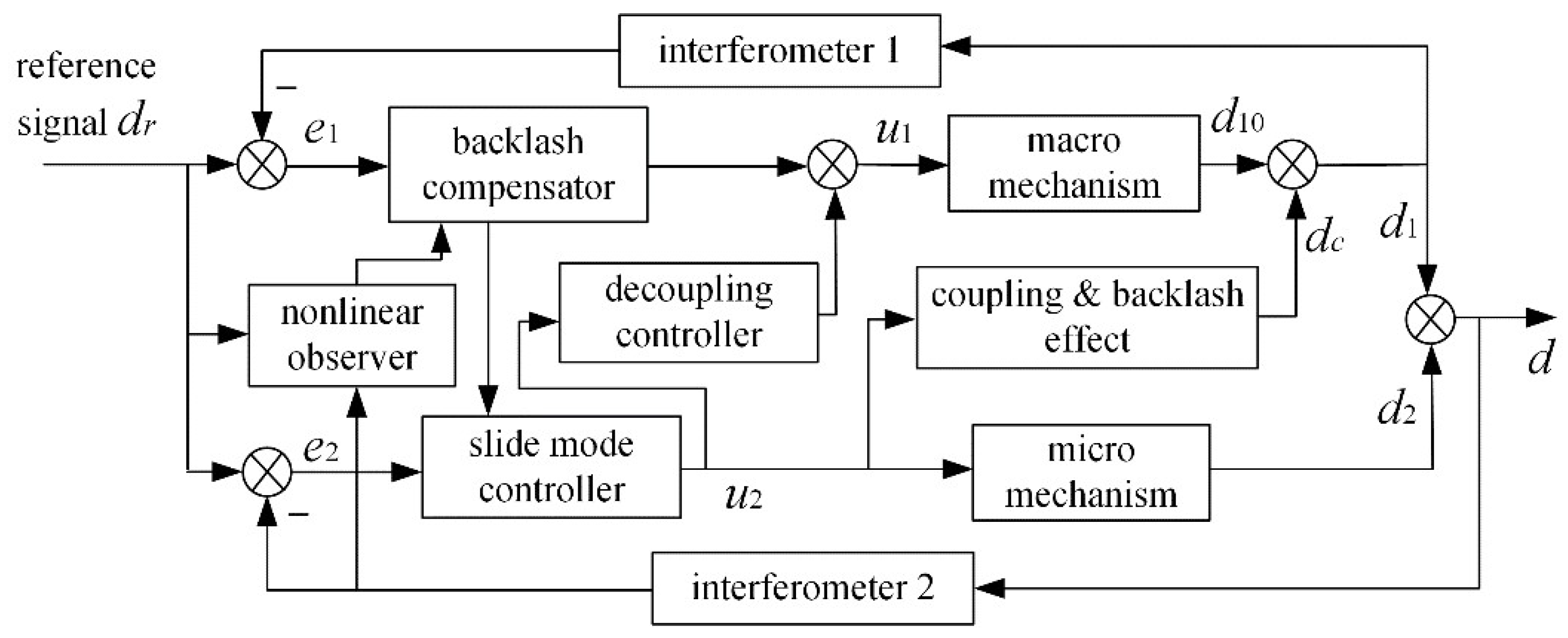
For challenge 2, according to the established model (1)–(5), a decoupling sliding mode control strategy based on backlash compensation is proposed in this section. According to the online identification result, the influence of the backlash disturbance force on macro and micro mechanisms is precisely compensated. Then, a decoupling controller is adopted to eliminate the influence of micro motion acting on the macro mechanism positioning. Next, an adaptive integral sliding mode control method for the micro mechanism is proposed to ensure both strong robustness and high-precision positioning of the end of the platform. The control schematic diagram is shown in Figure 7.
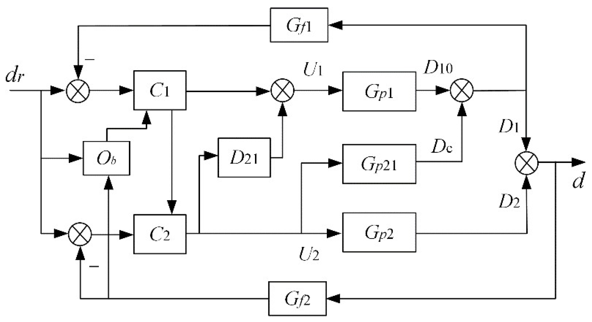
For the convenience of following the explanation, according to the control strategy shown in Figure 7, the control block diagram for the platform is given in Figure 8.
In Figure 8, d r is the displacement reference signal of the platform, O b represents the nonlinear velocity observer used to identify backlash parameters. C 1 and C 2 are the backlash compensator (including compensation for both macro/micro motion) and the sliding mode controller to be designed, respectively, and U 1 and U 2 are the corresponding control inputs generated by the above-mentioned controller, respectively. G p 1 and G p 2 represent the dynamics of the macro/micro mechanisms, respectively, and their corresponding responses are D 10 and D 2 , respectively. G f 1 and G f 2 represent the dynamics of the interferometer installed at the end of the macro/micro mechanisms, respectively. G p 21 represents the coupling and backlash combined dynamics in Equation (2), whose response under controller input U 2 is D c . D 21 is the decoupling controller to be designed, which can compensate for the influence of the micro motion reflected on the macro mechanism via the feedforward way.

4.1. Decoupling Control Design for Macro Mechanism Based on Backlash Compensation

Since the micro mechanism is installed at the end of the macro mechanism, the basic order of the platform positioning accuracy is mainly determined by the macro mechanism. In order to improve the overall positioning accuracy, the coupling effect from the micro mechanism acting on the macro positioning must be effectively eliminated.
However, under the backlash effect, the coupling force exists in a discontinuous form as expressed by Equation (5), which makes the system dynamic nonlinear. Thus, the coupling effect can hardly be eliminated by common linear decoupling methods. To overcome this problem, the backlash influence must be accurately compensated for before decoupling, that is, a backlash compensator for macro motion should be provided. Here, combining the nonlinear observer (12) and RLS method (20), the compensator can be given as
d 1 b t = x ^ 1 w t x ^ 1 h t f o r   b a c k l a s h   s t a t e 0 f o r   n o n - b a c k l a s h   s t a t e
where d 1 b t indicates the time-varying compensation value for the macro mechanism, and the backlash state is determined by the state factor δ b . Due to the finite-time convergence characteristic of observer (12), d 1 b t can be obtained timely in each control interval, thus eliminating the backlash discontinuous influence in the corresponding control period.
Then, G p 1 and G p 21 can be rewritten as their linear form G ¯ p 1 and G ¯ p 21 , ensuring that the macro/micro coupling effect can be directly compensated for via a linear decoupling method. In this case, the system dynamics must be satisfied
U 2 G ¯ p 21 + U 2 D 21 G ¯ p 1 = 0
then we have
D 21 = G ¯ p 21 G ¯ p 1
According to Equations (1)–(4), G p 21 and G p 1 can be indicated as
G ¯ p 21 = D c s U 2 s = K c A s 3 + B s 2 + C s + E
G ¯ p 1 = D 10 s U 1 s = K m h L h m 1 s 3 + L h b 1 + R h m 1 s 2 + ( R h b 1 + K m h K e m f h ) s
where K c , A , B , C , E are the coefficients of the coupling transfer function, which can be obtained via experimental identification. From Equations (23)–(25), the decoupling controller is designed as
D 21 = K c K m h L h m 1 s 3 + L h b 1 + R h m 1 s 2 + ( R h b 1 + K m h K e m f h ) s A s 3 + B s 2 + C s + E
By choosing appropriate control parameters based on the identification result, the stability of the macro positioning control loop can be ensured.

4.2. Adaptive Integral Sliding Mode Positioning Control Design for Micro Mechanism

In this section, an integral sliding mode control method based on backlash compensation is proposed to improve the micro positioning accuracy. By designing a nonlinear sliding mode surface, and estimating the upper bound of residual disturbance adaptively, the controller will ensure the total displacement of the platform’s end converges to the reference signal within the designated tracking error range.
As can be seen from Equation (2), backlash disturbance term F b will introduce oscillation and affect micro positioning accuracy. However, if only adopting the sliding mode robust term to suppress oscillation here, the control algorithm will get too conservative; therefore, a feedforward compensation of F b for micro motion has to be carried out according to the disturbance observer (17). Then, further considering the influence of external disturbances, the dynamics (2)–(4) for the micro mechanism can be rewritten as
m 2 d ¨ + K 2 d + b 2 d ˙ Δ F b m 2 d ¨ 1 b ^ ¨ + b 2 d ˙ 1 b ^ ˙ + K 2 d 1 b ^ = K m w i w F e x
u c w = L w d i w d t + R w i w + K e m f w d x w d t
where x w = d d 1 + b , and Δ F b is the residual force after backlash compensation, which is generated from the backlash estimation error. Let Ω e x be the upper bound of the external disturbance; then we have F e x Ω e x . If the upper bound of Δ F b is Ω b , then the total disturbance force f d = F e x + Δ F b for the motion system is also bounded, which can be expressed as f d Ω d = Ω e x + Ω b . Thus, the upper bound of the total disturbance can be estimated.
Due to the reason that L w / R w is much smaller than other coefficients, the influence of derivative term d i w / d t can be ignored; then, Equation (28) is simplified as
i w = 1 R w u c w K e m f w d x w d t
Define x = x 1 x 2 T = d d ˙ T , then the micro dynamics model (27) and (29) can be rewritten in state equation form as
x ˙ 1 = x 2 x ˙ 2 = 1 m 2 K 2 x 1 b 2 + K m w K e m f w R w x 2 + K m w R w u c w + K 2 d 1 b ^ + b 2 + K m w K e m f w R w d ^ ˙ 1 + m 2 d ^ ¨ 1 f d
where b ^ is the estimated backlash size obtained from Section 3, d ^ ˙ 1 , d ^ ¨ 1 are the actuator’s velocity and the acceleration of the macro mechanism estimated via Equation (12).
In order to ensure that the platform tracks the reference displacement signal, the tracking error is defined as
e = x 1 d r
the nonlinear integral sliding mode surface is designed as
s = e ˙ + η e + γ y e d t
where η and γ are control parameters to be designed, which satisfy η > 0 , γ > 0 . In order to further improve the tracking dynamic performance, design y e as the following piecewise function form
y e = 2 ϕ e 2 e ϕ > e > 0 ϕ sgn e e ϕ 2 ϕ e 2 e 0 > e > ϕ
where ϕ is set as the switch boundary of tracking error. Since the micro mechanism is used to compensate the micro positioning error generated from the macro mechanism, its travel range is much smaller than that of the macro part. Therefore, when the macro positioning error exceeds the designated boundary ( e ϕ ), the micro mechanism does not response; conversely, the compensation for the displacement micro-error starts. At that time, use y e to replace the integral term in the traditional sliding mode surface; thus, the small error can be “amplified”, that is, when e < ϕ , there is y e > e , then the high tracking accuracy for this dual-drive platform can be ensured, and the control strategy can also be switched in time when the required compensation exceeds the range of the micro mechanism.
When the system state reaches stable, s = s ˙ = 0 . Choose the first Lyapunov function V 1 as
V 1 = 1 2 m 2 s 2
Substituting Equation (32) and its derivative into V ˙ 1 , we have
V ˙ 1 = m 2 s s ˙ = s m 2 d ¨ r K 2 x 1 b 2 + K m w K e m f w R w x 2 + K m w R w u c 2 + s K 2 d 1 b ^ + b 2 + K m w K e m f w R w d ^ ˙ 1 + m 2 d ^ ¨ 1 f d + m 2 η e ˙ + m 2 γ y e
Since the total disturbance term f d is unknown, its upper bound Ω d will be estimated by adaptive control here. Define the estimated upper bound as Ω ^ d , the estimated error is
Ω ˜ d = Ω ^ d Ω d
Choose another Lyapunov function V 2 as
V 2 = V 1 + 2 α 1 Ω ˜ d 2
where α > 0 . According to Equations (36) and (37), we have
V ˙ 2 = V ˙ 1 + α 1 Ω ^ d Ω d Ω ^ ˙ d
Therefore, according to Equations (35)–(38), the adaptive integral sliding mode controller is designed as
u c 2 = R w K m w m 2 d ¨ r K 2 d 1 b ^ + b 2 + K m w K e m f w R w d ^ ˙ 1 + m 2 d ^ ¨ 1 + K 2 x 1 + b 2 + K m w K e m f w R w x 2 m 2 η e ˙ m 2 γ y e k r Ω ^ d s k s
where k > 0 and r > 0 are the control parameters for adjusting the tracking error convergence boundary. Furthermore, the adaptive law for estimating the upper bound of the total disturbance is designed as
Ω ^ ˙ d = α k r s 2
Theorem 1.
For the micro mechanism described in Equation (30), the control law (39) and adaptive law (40) are adopted to compensate macro positioning and ensure that the dual-drive platform’s tracking error e converges to the designed small neighborhood of the equilibrium point in finite time T s , and the motion system is also asymptotically stable.
Proof. 
Substitute Equations (39) and (40) into system (30), we get
V ˙ 2 = k r Ω ^ d s 2 k s 2 + f d s + 1 α Ω ^ d Ω d Ω ^ ˙ d
When s r / k , it satisfies
V ˙ 2 k s 2 k r Ω d s f d s 0
It can be seen that the tracking error will converge to the state equilibrium point as s converges to r / k , r / k in a finite time. To determine the convergence range of the tracking error, define the third Lyapunov function as follows:
V 3 = 1 2 e 2
It can be obtained from Equations (32), (33) and (43)
V ˙ 3 η e 2 γ e y e d t + r k e
Therefore, when the tracking error satisfies the following inequality
lim t T s , r k 0 e 3 8 ϕ + 9 64 ϕ 2 3 η ϕ 2 γ
V ˙ 3 0 holds. From Equation (45), by selecting appropriate sliding mode surface and control parameters ϕ , η , γ , r , k , the surface can be ensured to converge in a small, designed neighborhood, and the micro tracking error can also converge to the designed range. □

5. Simulation Results

5.1. Simulation Verification of Model Rationality for Macro-Micro Motion Platform with Backlash

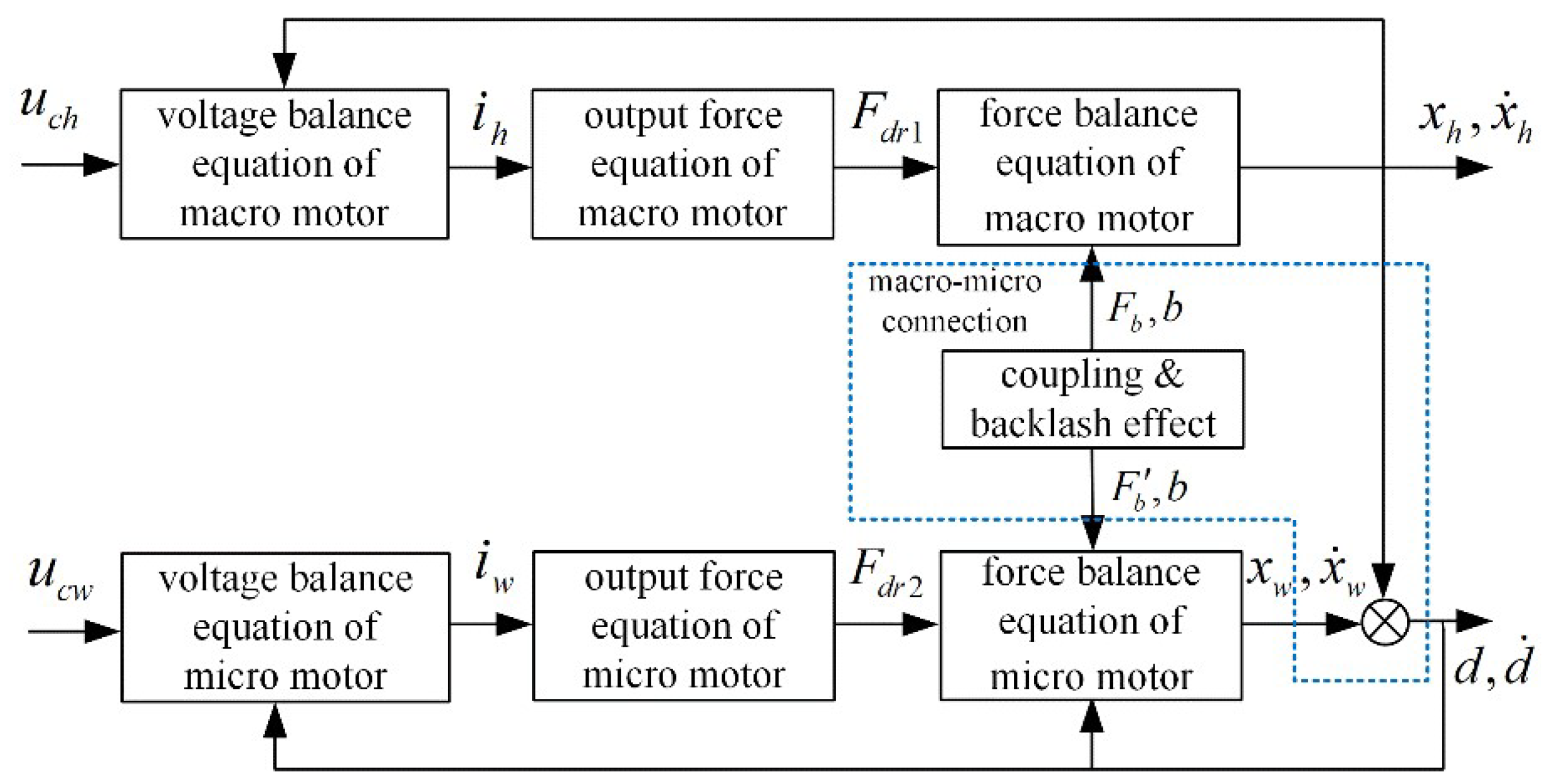
According to model (1)–(5), a nonlinear motion platform model containing macro/micro dynamics and backlash characteristics can be established; its structure is shown in Figure 9, where the part in the blue dashed box represents the interaction influence of macro-micro connection on each mechanism.
The parameters applied in the platform model for simulation are shown in Table 1. In order to ensure the validity of simulation, the nominal structure parameters in Table 1 are provided based on the motion platform described in Section 6.2.
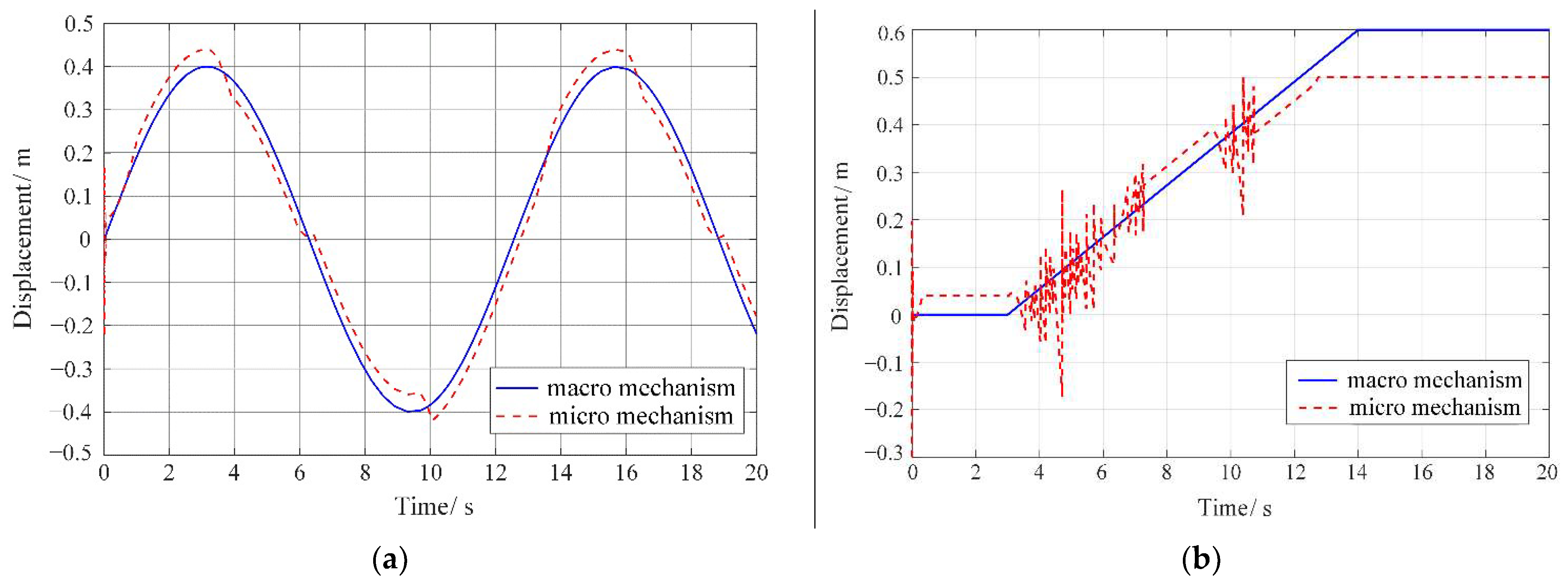
In order to verify the influence of macro–micro coupling with backlash on the platform positioning accuracy, the backlash width is set as b = 0.04 m here, two forms of displacement reference signals for the macro mechanism are selected as x h 1 = 0.4 sin 0.5 π t m and x h 2 = 0.6 / 11 t 3 m ( 3 t 14 ), the displacement reference signal for the micro mechanism is set as x w = 0.04 sin 2 π t m , and the displacement curve at the end of the platform can be obtained as shown in Figure 10.
When the macro mechanism drags the micro mechanism to move under control, the displacement curves of the platform’s end shown in Figure 10 both reflect similar trends to their corresponding reference signals. However, due to the coupling and backlash effect, the end’s displacement curves under different signals (shown by red dashed lines in Figure 10a,b) present distortion or oscillation (also called the limit-cycle phenomenon), which is consistent with the trend of the experimental phenomenon and verifies the rationality of the model (1)–(5).

5.2. Simulation Verification of Stepwise Nonlinear Backlash Identification Method

This section verifies the stepwise nonlinear identification method designed in Section 3.2: first, the sampling data required for backlash identification is generated via Equation (10) under the above-mentioned working conditions, where the nominal parameters are set as Table 2, and the model excitation signal is set to F e s t = 0.1 sin ( 0.2 π t ) (kN). Then, discrete data (the sampling time is set to 1 ms) is substituted into the second-order sliding mode nonlinear observer (12); by combining the RLS method (20), the backlash parameters in model (5) can be obtained. Finally, the identified backlash value is compared with the nominal value to verify the effectiveness of the designed method.
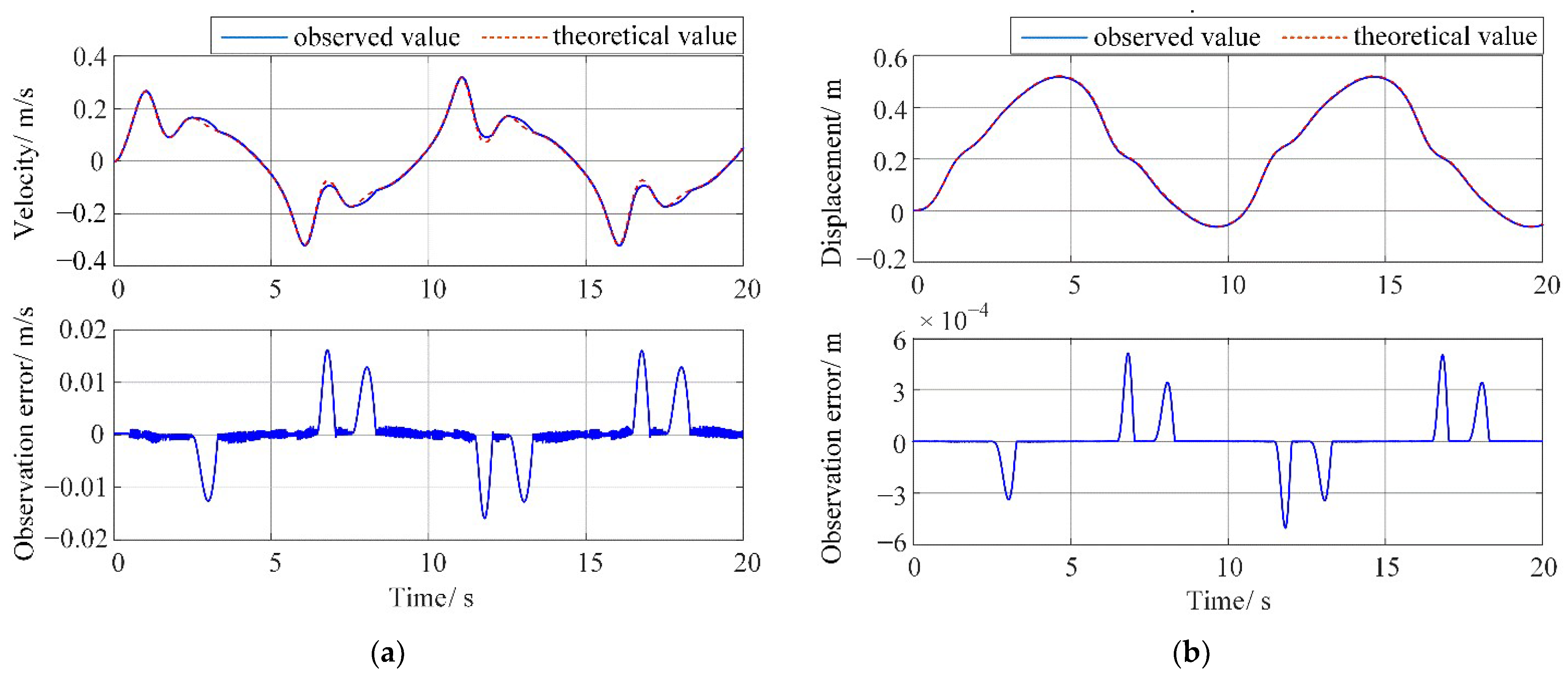
According to observer stability conditions (13), the observer parameters are selected as η 1 = 1.65 , η 2 = 0.06 , ι 1 = 0.7 and ι 2 = 0.03 . Even if the data outputs from sensors have already been filtered by hardware, the low-pass filter used to eliminate the high-frequency oscillation of states is still needed and selected as 0.0244 + 0.0244 z 1 / 1 0.9512 z 1 . Thus, the observed speed, position and observation error of the macro mechanism are shown in Figure 11.
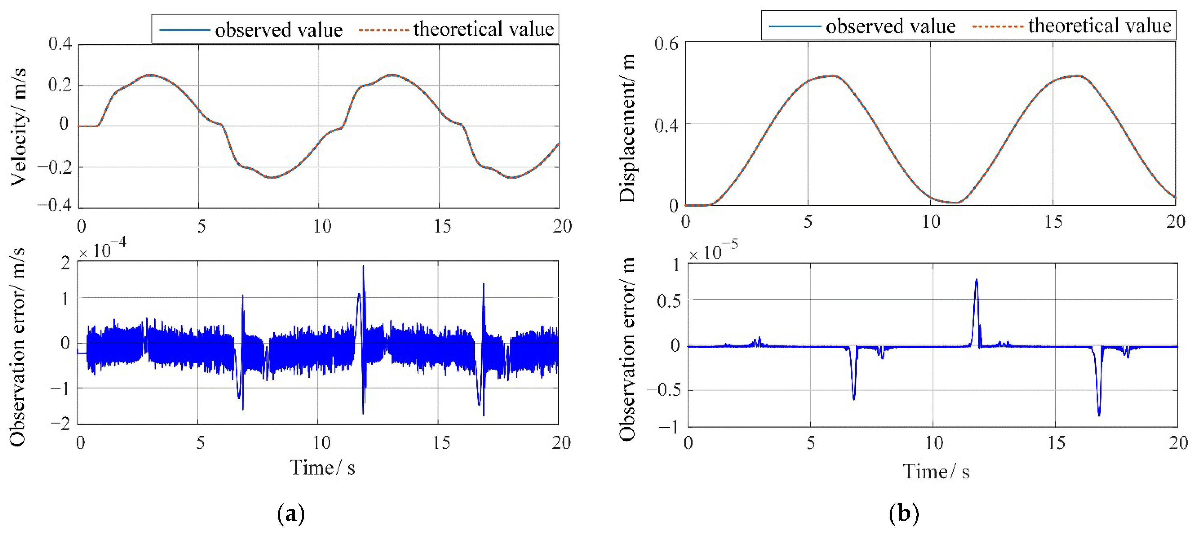
The observed velocity, position and observation error of the end of the micro mechanism are shown in Figure 12.
From Figure 11 and Figure 12, it can be found that the trends of observed curves are basically consistent with the corresponding theoretical curves. The maximum observation errors of the velocity and position for the macro mechanism are about 5.67% and 0.283%, respectively, while the observation errors of the velocity and position for the micro mechanism are only 0.192% and 0.0769%, respectively. Therefore, the designed nonlinear observer expresses quick convergence and strong robustness, which is not easily affected by parameter perturbation.
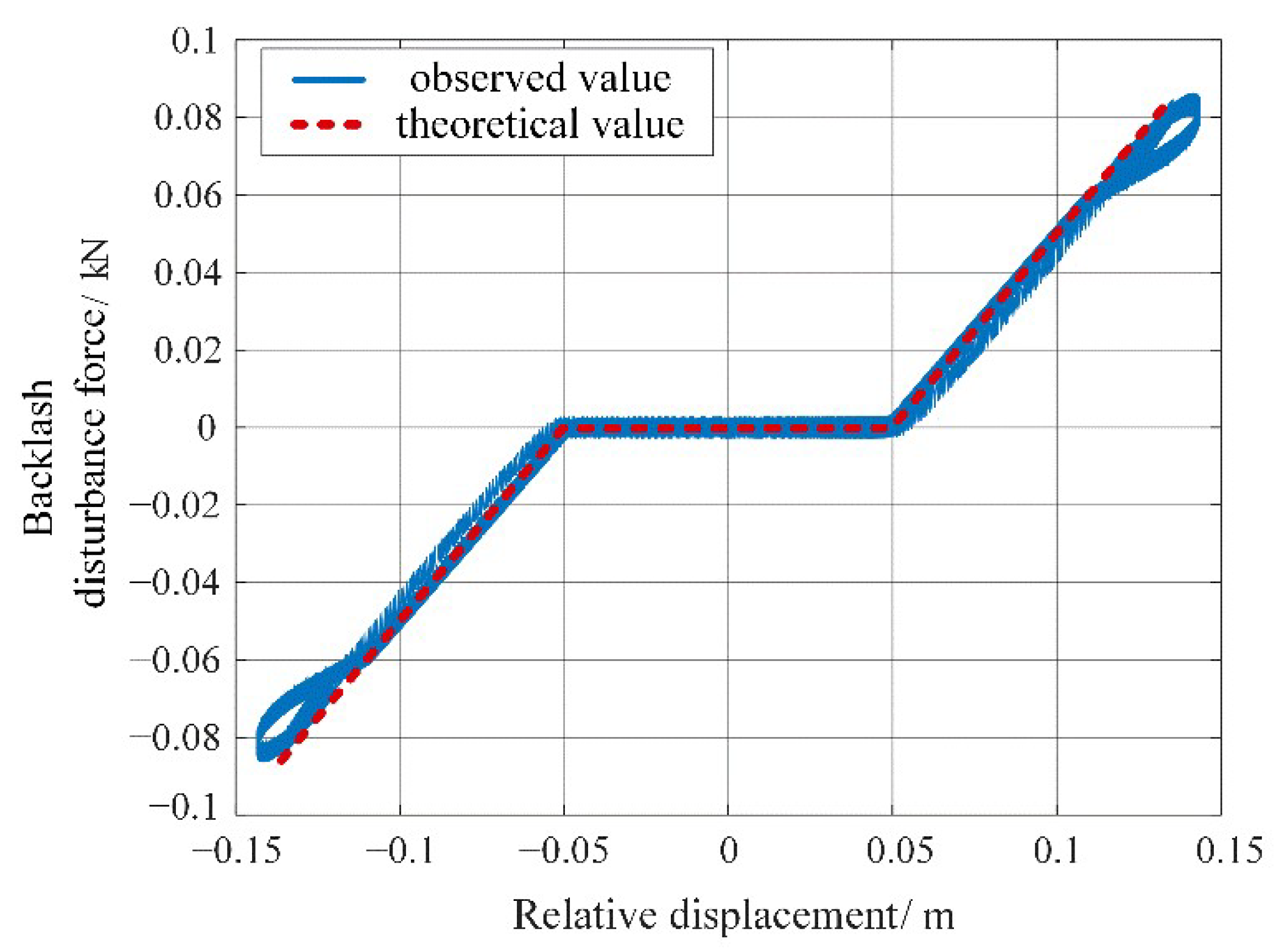
According to Equations (16) and (17), the disturbance force transmitted by the backlash can be calculated from the observed velocity and position above; its estimated curve (shown in Figure 13) is basically consistent with the trend of the theoretical one. It should be noted that the observation data need to be filtered before preprocess, since the second-order sliding mode observer will introduce oscillation into the estimation. However, considering the lag effect caused by the filter on the signal, a large time constant should not be selected.
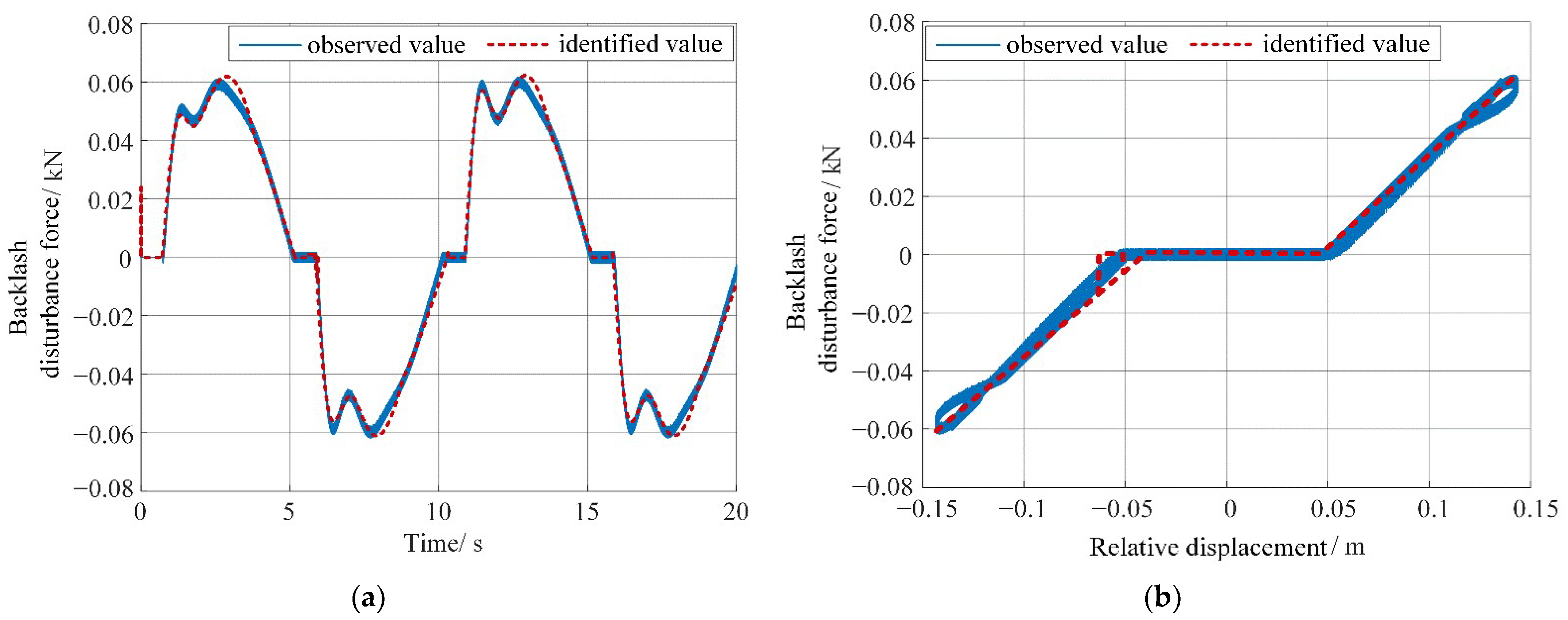
Then, based on the estimated disturbance force data, the backlash parameters can be identified according to the procedure in Step B of Section 3.2. The disturbance force curve identified by RLS is shown in Figure 14.
As can be seen from Figure 14, there exists a large deviation at the initial and also reverse stages; however, the identification results are basically consistent with theoretical values in the region containing backlash. The identified backlash parameters are listed in Table 3.
According to Table 3, the corresponding identification errors are 5.20%, 7.40%, 11.3% and 12.4%, respectively. It should be noted that the above error is the accumulation of estimation errors from the two-step identification process. Considering the numerical errors in corresponding travel ranges are acceptable, we can reach the conclusion that the designed backlash identification method is effective.

5.3. Simulation Verification of Decoupling Sliding Mode Compound Positioning Control

To prove the validity of the proposed DSMC method in Section 4, the platform positioning performance will be demonstrated under different displacement reference signals, which are selected as a sinusoidal signal x r e f 1 = 0.5 sin 0.75 t m and a trapezoid signal x r e f 2 shown in Figure 15b, respectively. System parameters are set as shown in Table 1, the backlash width is set to 0.015 m, and the sampling time is set to 1 ms. It should be noted that the backlash width set in the simulation is much larger than the actual backlash (about 75 times) in order to verify the general effectiveness of our algorithm on backlash compensation. At the same time, the positioning performance under traditional double-loop PID control without backlash compensation and the designed DSMC control strategy are both presented below for comparison.
Case (A)
Double-loop PID control strategy without backlash compensation
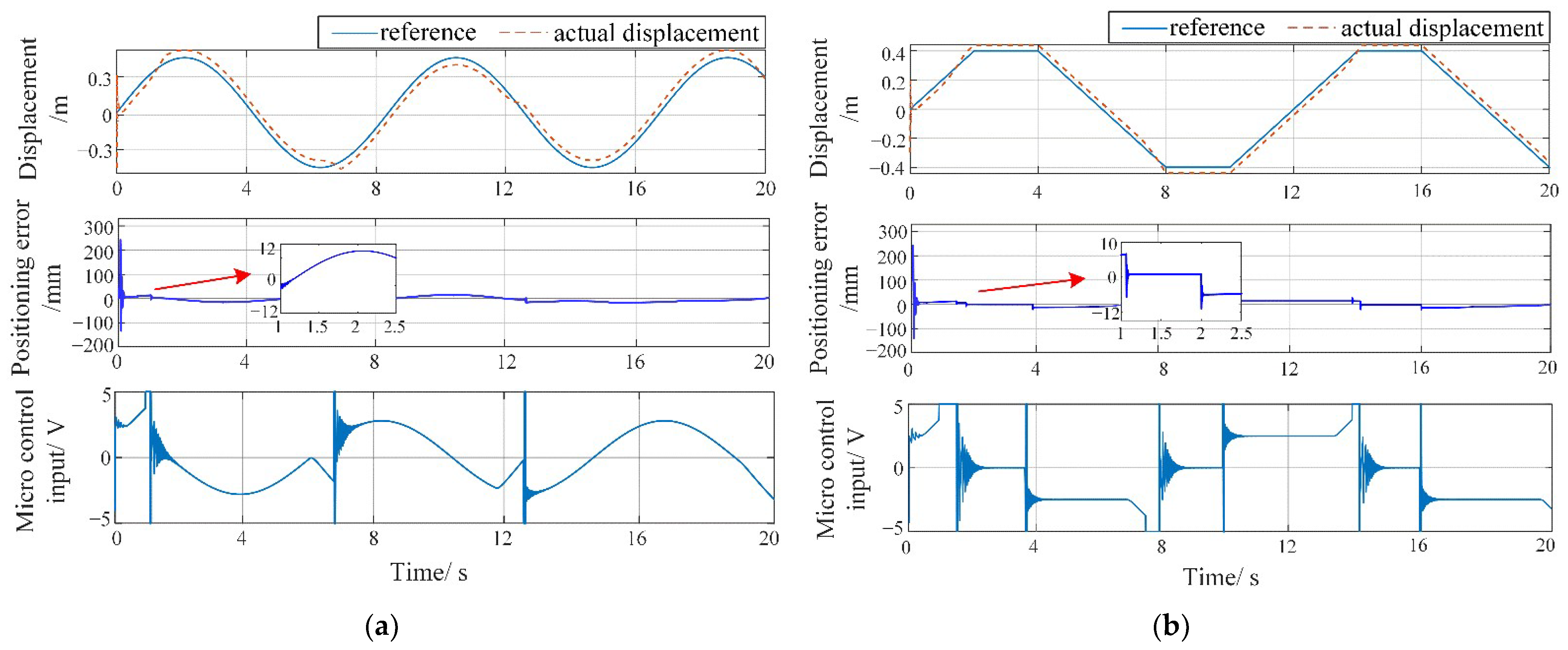
PID control strategy (including positioning compensation) is widely used in motion control situations due to its model-free characteristic and convenient control parameters’ adjustment. Considering that the backlash characteristic is unknown and no compensation is added, the control parameters for macro/micro mechanisms are selected as P h = 1.0012 and P w = 0.4 , I w = 0.001 , D w = 0.0005 , respectively, and the dynamic responses of the platform under different reference signals is shown as Figure 15.
As can be seen from Figure 15, when no backlash compensation is provided, there is always a certain error between the actual displacement of the platform’s end and the reference signal. Although the stable positioning error is less than the backlash width under control, the signal jump caused by backlash discontinuities is still difficult to eliminate completely.
In Figure 15a, the displacement curve at the initial stage shows a large oscillation, and so does the corresponding micro control voltage at backlash jump points, which even reaches the voltage boundary. The stable tracking error is within the range of [−12, 11] mm, and the average positioning error is about 6.7%. The curve in Figure 15b also reflects a similar situation. The stable tracking error is within the range of [−12, 10] mm, and the average positioning error is 7.9%. In summary, it can be seen that adopting a double-loop PID control method can hardly help the macro-micro platform with a total stroke of 1 m achieve micron positioning accuracy under backlash influence.
Case (B)
DSMC control strategy based on backlash compensation
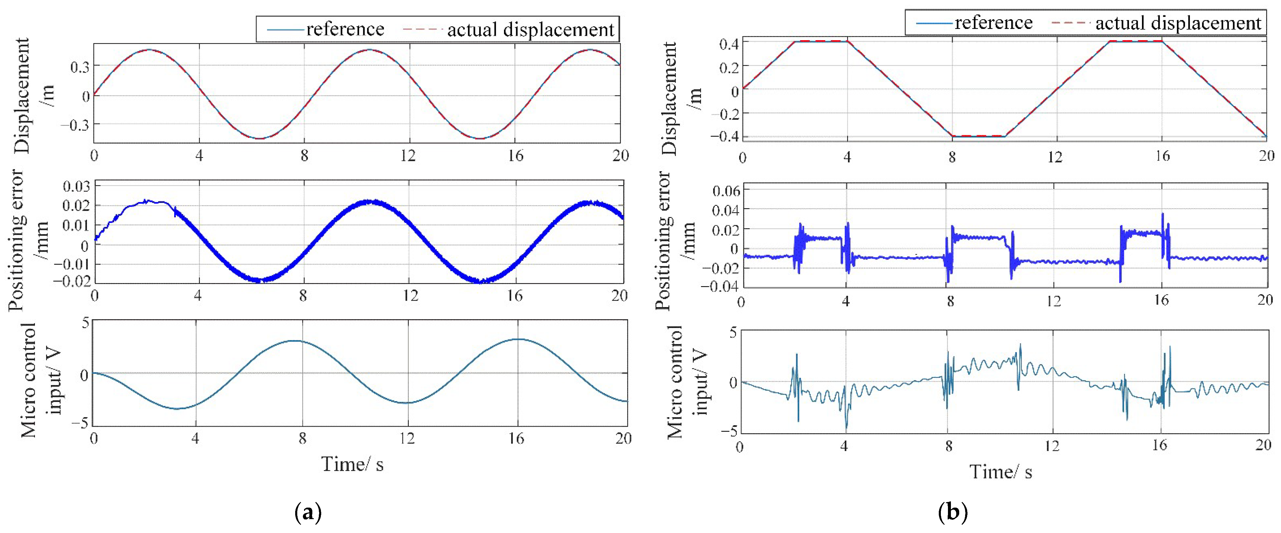
According to Equations (39) and (40), designed controller parameters are selected as follows: gain P h = 1.0008 for the macro decoupling controller, SMC parameter for the micro controller η = 1.8 × 10 4 , γ = 697.5 , k = 310.2 , r = 20 , α = 800 , the upper limit of tracking error is set as ϕ = 3.01 × 10 5 , the initial value of disturbance’s upper bound for estimation is chosen as Ω ^ d 0 = 0.05 , backlash observer parameters are set as those in Section 5.2. Thus, the dynamic responses of the platform under different reference signals are shown as Figure 16.
From Figure 16, by applying backlash online estimation and compensation, the displacement curve does not express the jump phenomenon caused by backlash, and the overall trend is relatively smooth. Thus, it can be seen that adopting the designed method can effectively improve the dynamic performance of the motion platform, although the backlash width set in the simulation is much larger than the actual one.
In Figure 16a, the displacement error curve is relatively smooth at the initial stage; then, a small oscillation appears (the error curve becomes thicker), which may be caused by the large attraction domain of the sliding mode observer. The micro control voltage always falls within the required boundary, overcoming the influence of signal saturation on the positioning accuracy. The stable tracking error is within the range of [−0.018, 0.022] mm, indicating that the platform can achieve micron-level positioning accuracy even under a large backlash disturbance (the width is set as 0.015 m). Its average positioning error is 0.015%, and the maximum positioning error has been reduced 99.7% compared to the corresponding result in Figure 15a. In Figure 16b, the stable tracking error is within the range of [−0.017, 0.019] mm (average positioning error 0.018%), and the maximum positioning error has been decreased 99.6% compared to the corresponding result in Figure 15b, only small error jumps existing when the motion state switches. The control voltage also jumps slightly at the corresponding switch points without signal saturation, which ensures positioning accuracy in all situations.

6. Experimental Results

In this section, the proposed stepwise backlash identification method, the effectiveness of the system model (1)–(5) associated with the current control performance of the platform will be verified in practice.

6.1. Experimental Validation of Stepwise Nonlinear Backlash Identification

The online backlash identification method (Section 3.2) is implemented on a test rig whose backlash parameters are already known (measured directly).
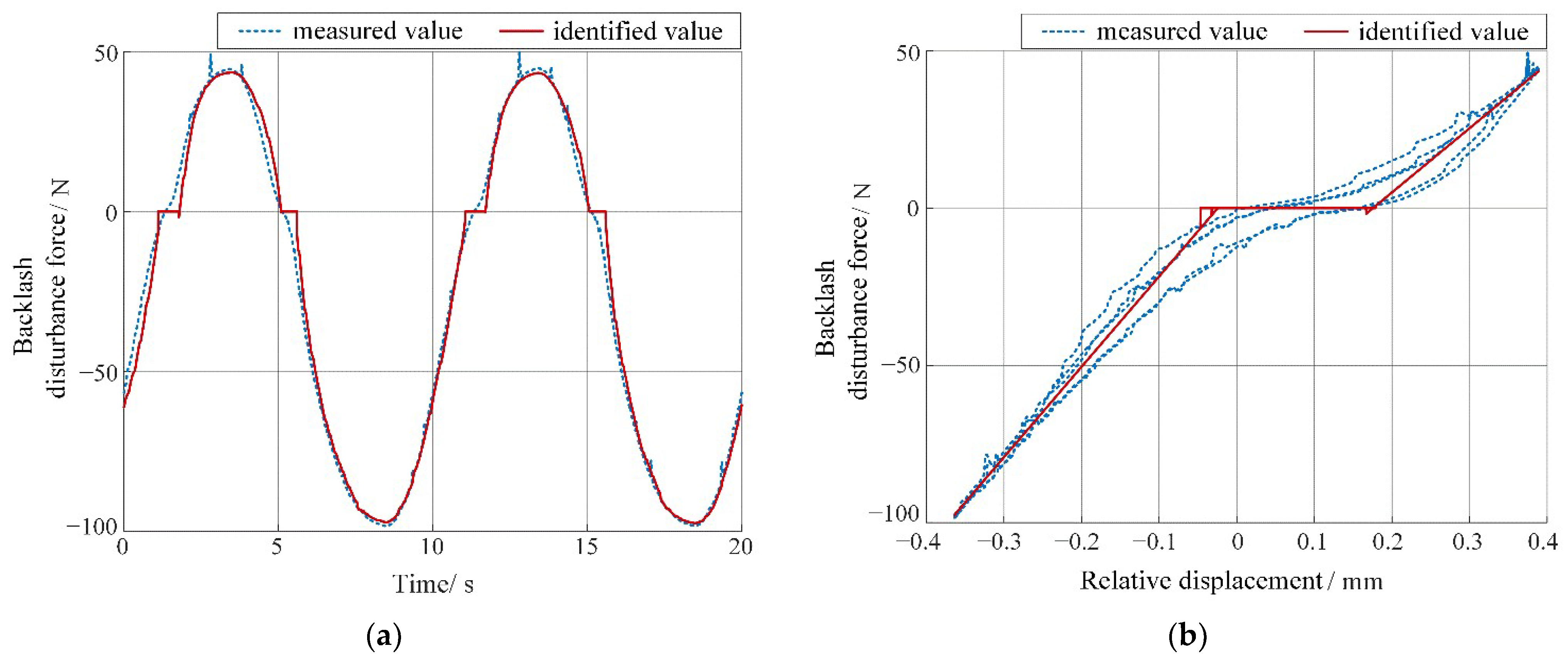
First, 5 groups of displacement and velocity data from macro/micro mechanism are respectively collected under the designated working conditions. Next, the input force reference signal and the collected displacement and velocity data are all substituted into Equations (9), (16), (17) and (20) to iteratively calculate backlash parameters in each sampling period for the test rig. Thus, the estimated backlash dynamics and characteristic are obtained as in Figure 17.
The backlash identification parameters calculated according to Figure 17b (red solid line) are b l = 0.0254 m m , b r = 0.176 m m , k l = 13.2 N / m m and k r = 9.87 N / m m . Although there exists hysteretic trend in the experimental curve, it still can be approximately regarded as a dead zone, theoretically, since the hysteresis amplitude is small. Therefore, the backlash width between macro and micro mechanisms is about 0.201 mm, and two equivalent stiffness coefficients for describing the macro mechanism pushes or pulls are not equal; the identified backlash model in the actual test rig is
F b t = 9.87 x b t 0.176 x b t 0.176 0 0.0254 x b t 0.176 13.2 x b t + 0.0254 x b t 0.0254
It is worth noting that the identified backlash width is 6.31% larger than the measured width (0.187 mm). Since the measured disturbance force in Figure 17a (blue dashed line) presents a continuous form without obvious segmental points, the identification error is inevitable when applying the segmented quasi-linear backlash model to find the precise state-switching points (marked by δ b in Equation (7)); hence, the identified backlash amplitude will be slightly larger than the actual one to some extent.

6.2. Experimental Validation of Decoupling Sliding Mode Compound Positioning Control

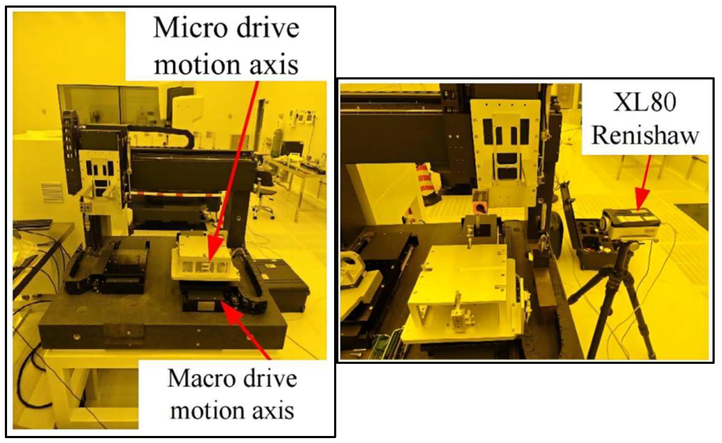
Due to the setting limit on printing scan paths of the test rig in practice, the backlash influence on positioning precision generally occurs randomly, which leads to a difficulty in predicting its acting time-points and then fully reflecting the compensation effectiveness of the proposed control strategy by experiment directly. Consequently, this subsection needs to first verify the accuracy of the established model by comparing the simulation and experiment results under the same PID controller on the motion platform shown in Figure 18 (a similar type of motion platform applied in OLED printing equipment, and its displacement is measured using laser interferometer Renishaw XL 80); then, combining the simulation performance in Section 5.3 (Case B) on the verified model, the effectiveness of DSMC strategy can be proved indirectly.
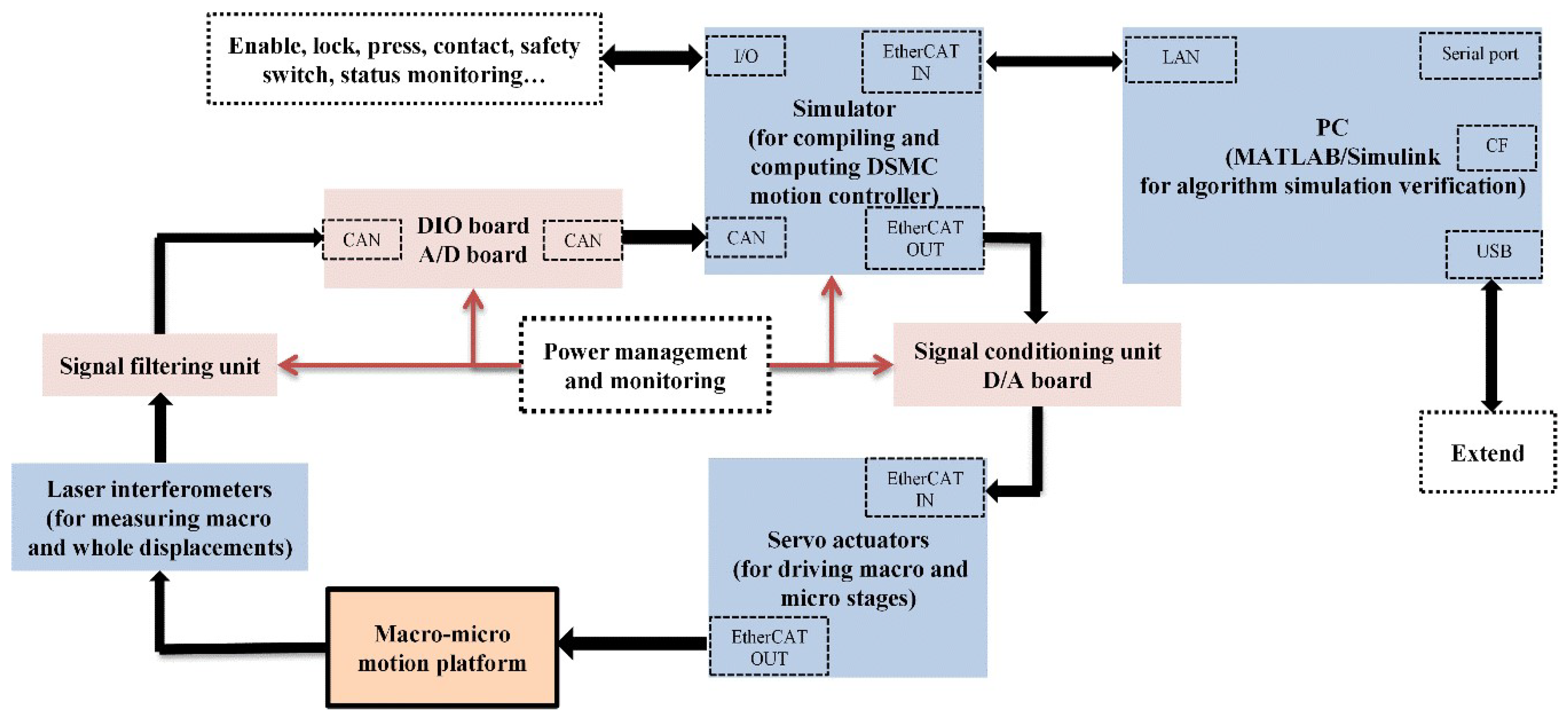
The schematic diagram of above test rig’s architecture is given as Figure 19. In Figure 19, PC, simulator, actuators and interferometers (in blue boxes) are key components for motion control, and macro–micro motion platform is the control plant (in the orange box). The designed controller can be compiled and computed via the simulator in each period, and then sent to corresponding servo actuators of macro and micro stages as their control inputs in each control interval.
In the experiment for model accuracy validation, two types of displacement reference signals are selected as the similar form as x r e f 1 and x r e f 2 with different amplitudes and frequencies (defined as sinusoidal signal I and II and trapezoidal signal I and II, respectively), due to the current test rig’s limit. The system refreshing period is 1 ms, which is the same as the simulation step. In addition, different types of sensors to detect displacement and velocity of macro and micro mechanisms are installed accordingly.
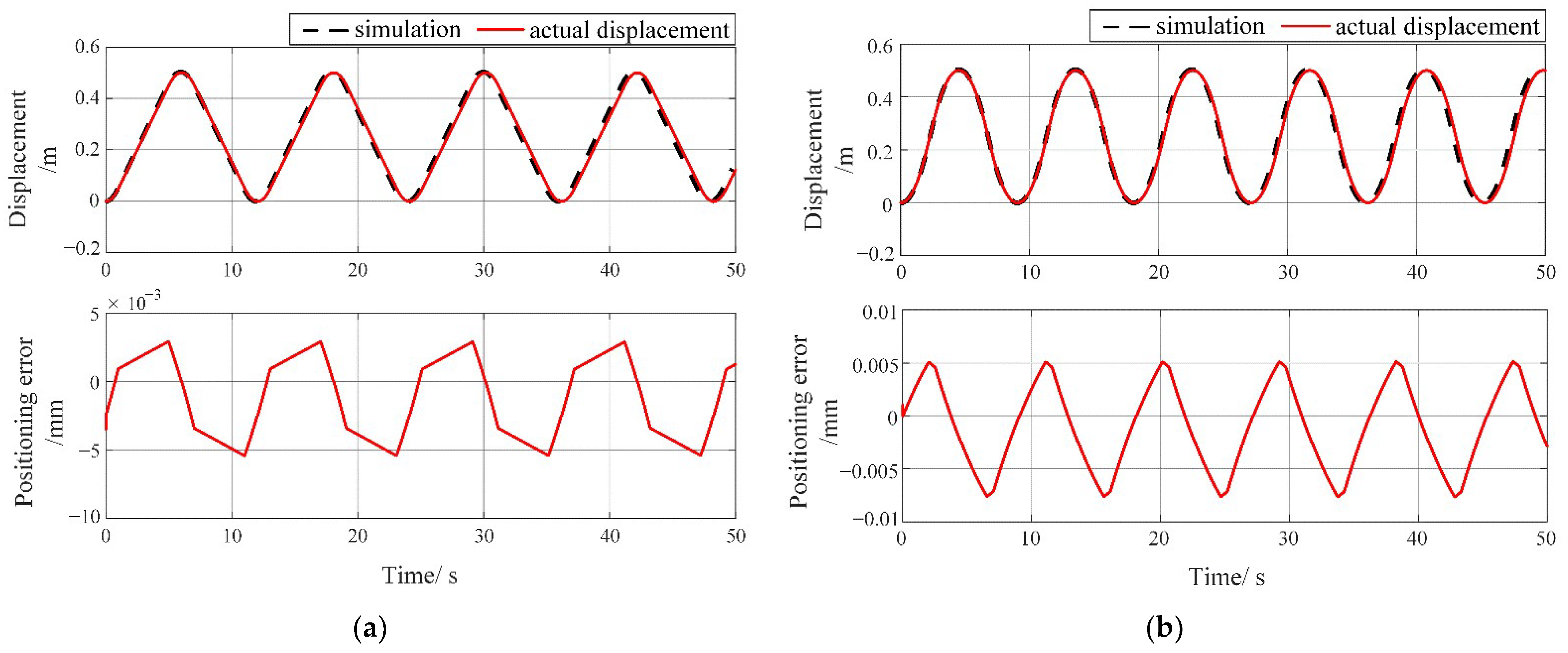
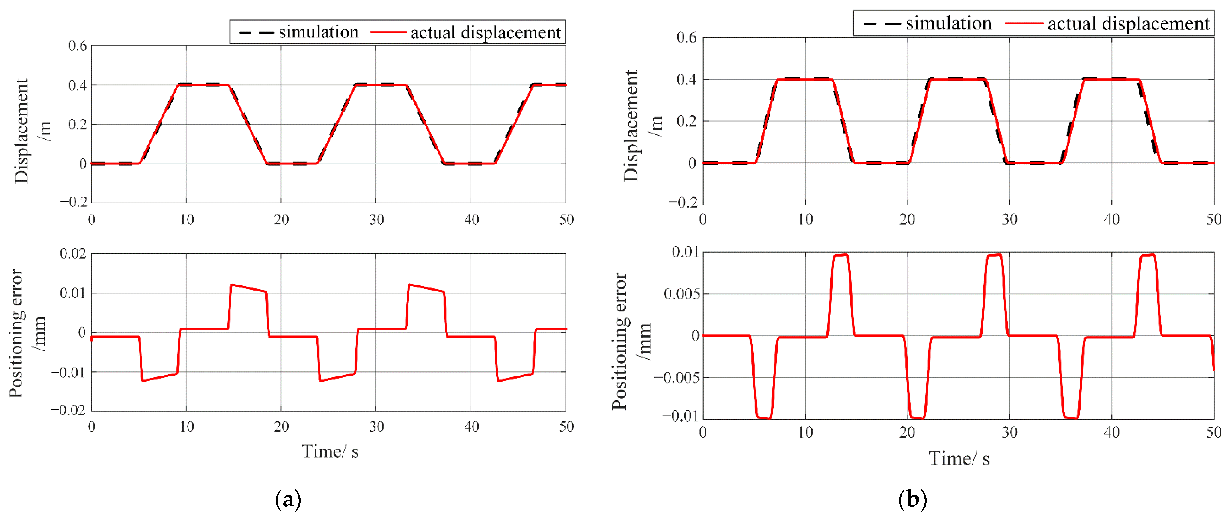
For the convenient comparison and analysis of the model’s accuracy, both the simulation and experimental results under same PID control are given in Figure 20 and Figure 21.
In Figure 20, the simulation responses under two approximated sinusoidal signals both express a slight lead over the corresponding experiment results due to the filter influence from the sensors, and the two positioning errors between them only reach maximum 7.5 μm, which reflects a good correspondence under the same PID controller and further verifies the accuracy of the established model. Figure 21 basically shows no error between simulation and experiment results when no displacement happens, but an error jump (maximum 10.2 μm) will occur correspondingly at each point of the acceleration changing, demonstrating both the influence of mechanism reversing with backlash and model correctness.
Owing to the setting limit of the current test rig we use, the effectiveness of designed DSMC still has difficulty in being proved directly. However, since the model accuracy has already been verified above by comparing the simulation and experiment results under the same PID controller, and the simulation results based on the verified model under proposed DSMC strategy (in Section 5.3 Case B) also shows great dynamics, it can be deduced indirectly that the actual DSMC control performance implemented on the practical test rig will also reach the same designated control indexes as those of the corresponding simulation.
In summary, combining the identification method, experimental verified platform model and DSMC simulation results, we can reach the final conclusion that the positioning accuracy and control dynamics of macro–micro dual-drive platform including backlash can be both greatly enhanced by applying proposed DSMC control strategy, decreasing to approximately 20~30 μm of positioning error without obvious jumps when movement reversing.

7. Conclusions

In this paper, a quasi-linear backlash-improved model is first proposed, and the dynamic model of the macro–micro dual-drive motion platform, including the combined effect of the backlash and macro–micro coupling, is also established. Secondly, in order to accurately estimate the backlash effect online for compensation, a stepwise nonlinear identification method based on the quasi-linear model is proposed accordingly. Then, a decoupling adaptive integral sliding mode compound control strategy is designed, associated with online backlash compensation to realize micron-level accuracy for macro–micro cooperative motion under the influence of backlash and coupling. Simulation and experimental results both show that the motion states can converge to a tiny neighborhood of the actual value within 0.2 s during online estimation, and the average identification error of backlash parameters is about 6.3% by adopting the proposed identification method. By combining backlash compensation, simulation results demonstrate that the platform’s positioning accuracy under sinusoidal and trapezoidal reference signals reaches an average 20 μm and 18 μm with a stroke of 1 m and 0.8 m, respectively, and its corresponding average positioning errors have been reduced to 0.015% and 0.018% when utilizing the DSMC strategy, which outperforms the results under the traditional PID method. In summary, the proposed control strategy combined with this identification method can significantly improve the positioning accuracy of this kind of macro–micro dual-drive motion platform under general working conditions.
In further research, our test rig will be upgraded, and validation experiments on the DSMC strategy will still be carried out once test conditions allow. Subsequently, other considerations related to high-precision positioning performance and printing efficiency, such as dismatched environmental disturbance suppression, multi-axis path planning for ultra large-area printing, top-level safety-critical cooperative positioning control design, etc., will be taken into account based on current research results to further enhance both the control performance and industrial practicality of this kind of system applied in large-scale OLED/Micro-LED inkjet printing equipment.

Author Contributions

Conceptualization, S.K.; software, S.K.; validation, B.Z. and X.H.; data curation, R.Z. and S.H.; writing—original draft preparation, S.K.; writing—review and editing, S.K., B.Z., R.Z. and S.H.; supervision, X.H.; project administration, B.Z. All authors have read and agreed to the published version of the manuscript.

Funding

This research is funded by GuangDong Basic and Applied Basic Research Foundation, grant number 2021A1515111134.

Data Availability Statement

Data available on request from the authors.

Conflicts of Interest

The authors declare no conflict of interest. The funders had no role in the design of the study; in the collection, analyses, or interpretation of data; in the writing of the manuscript; or in the decision to publish the results.

References

  1. Xie, X.; Qi, C.; Tan, R.Y.; Fan, D. Design and performance analysis of a many-to-one configuration precise cable drive mechanism with high precision and large torque. Proc. Inst. Mech. Eng. Part C J. Mech. Eng. Sci. 2019, 233, 5903–5915. [Google Scholar] [CrossRef]
  2. Yang, M.; Wang, C.; Zheng, W.L.; Hu, K.; Xu, D. Analysis and suppression of limit cycle oscillation for transmission system with backlash nonlinearity. IEEE Trans. Ind. Electron. 2017, 64, 9261–9270. [Google Scholar]
  3. Dong, R.L.; Tan, Q.Y.; Tan, Y.H. A nonsmooth nonlinear programming based predictive control for mechanical servo systems with backlash-like hysteresis. Asian J. Control 2018, 20, 1519–1532. [Google Scholar] [CrossRef]
  4. Li, L.; Lin, Z.Y.; Jiang, Y.; Yu, C.; Yao, J. Valve deadzone/backlash compensation for lifting motion control of hydraulic manipulators. Machines 2021, 9, 57. [Google Scholar] [CrossRef]
  5. Yu, J. Research on Coupling Characteristics of Planar 3-RRR Parallel Mechanism Control and Macro and Micro Precision Positioning System. Master’s Thesis, South China University of Technology, Guangzhou, China, 2018. [Google Scholar]
  6. Wang, W.X.; Ma, J.; Cheng, Z.L.; Li, X.; de Silva, C.W.; Lee, T.H. Global iterative sliding mode control of an industrial biaxial gantry system for contouring motion tasks. IEEE/ASME Trans. Mechatron. 2022, 27, 1617–1628. [Google Scholar] [CrossRef]
  7. Wang, X.Y.; Yu, N.B.; Bie, D.Y.; Han, J.; Fang, Y. A novel ESMF-based observer and control scheme for a type of tendon-sheath hysteresis system. Automatica 2021, 131, 109800. [Google Scholar] [CrossRef]
  8. Anjum, Z.; Zhou, H.; Guo, Y. Self-tuning fuzzy nonsingular proportional-integral-derivative type fast terminal sliding mode control for robotic manipulator in the presence of backlash hysteresis. Trans. Inst. Meas. Control 2022, 44, 809–819. [Google Scholar] [CrossRef]
  9. Zhang, L.Y.; Gao, J.; Chen, X.; Tang, H.; Chen, Y.; He, Y.; Yang, Z. A rapid vibration reduction method for macro-micro composite precision positioning stage. IEEE Trans. Ind. Electron. 2017, 64, 401–411. [Google Scholar] [CrossRef]
  10. Dong, W.; Chen, F.X.; Li, H.Y.; Yang, M.; Du, Z. A two-dimensional nano-positioner: Design, modelling and experiments. Robot. Comput.-Integr. Manuf. 2017, 48, 167–173. [Google Scholar] [CrossRef]
  11. Zhang, R.; Gao, L.X. Research on motor control and simulation based on PID and Internet of Things system. Microprocess. Microsyst. 2021, 80, 103602. [Google Scholar] [CrossRef]
  12. Chen, F.X.; Zhang, Q.J.; Dong, W.; Sun, L. Design and test of a compact large-stroke dual-drive linear-motion system. Mech. Syst. Signal Process. 2022, 180, 109438. [Google Scholar] [CrossRef]
  13. Yue, H.; He, H.; Han, M. Study on torsional vibration characteristics and suppression of electric vehicles with dual-motor drive system. J. Frankl. Inst. 2023, 360, 380–402. [Google Scholar] [CrossRef]
  14. Lin, Z.C.; Liu, K.; Zhang, L.; Zeng, D. Coupling effect and control strategies of the maglev dual-stage inertially stabilization system based on frequency-domain analysis. ISA Trans. 2016, 64, 98–112. [Google Scholar] [CrossRef] [PubMed]
  15. Zhao, B.; Shi, W.J.; Tan, J.B. Design and control of a dual-stage actuation active vibration isolation system. IEEE Access 2019, 7, 134556–134563. [Google Scholar] [CrossRef]
  16. Yabui, S.; Atsumi, T. High-bandwidth controller design for dual-stage actuator system in hard disk drives. J. Vib. Control 2023, 29, 1268–1279. [Google Scholar] [CrossRef]
  17. Lin, C.Y.; Chang, C.Y. Repetitive model predictive control for precise control of complex trajectory tracking in dual-stage actuator systems. Proc. Inst. Mech. Eng. Part I J. Syst. Control Eng. 2017, 231, 213–229. [Google Scholar] [CrossRef]
  18. Zeng, T.Y.; Ren, X.M.; Zhang, Y. Fixed-time sliding mode control and high-gain nonlinearity compensation for dual-motor driving system. IEEE Trans. Ind. Inform. 2020, 16, 4090–4098. [Google Scholar] [CrossRef]
  19. Ping, Z.W.; Wang, T.; Huang, Y.Z.; Wang, H.; Lu, J.-G.; Li, Y. Internal model control of PMSM position servo system: Theory and experimental results. IEEE Trans. Ind. Inform. 2020, 16, 2202–2211. [Google Scholar] [CrossRef]
  20. Garrido, R.; Luna, L. Robust ultra-precision motion control of linear ultrasonic motors: A combined ADRC-Luenberger observer approach. Control Eng. Pract. 2021, 111, 104812. [Google Scholar] [CrossRef]
  21. Nagel, W.S.; Clayton, G.M.; Leang, K.K. Master-slave control with hysteresis inversion for dual-stage nanopositioning systems. In Proceedings of the 2016 American Control Conference (ACC), Boston, MA, USA, 6–8 July 2016. [Google Scholar]
  22. Bagherieh, O.; Horowitz, R. Mixed H2/H-infinity data-driven control design for hard disk drives. In Proceedings of the 2018 Asia-Pacific Magnetic Recording Conference (APMRC), Shanghai, China, 15–17 November 2018. [Google Scholar]
  23. Shah, P.; Horowitz, R. Data driven feedforward control design and input shaping techniques for multi actuator drives. ASME Lett. Dyn. Syst. Control 2021, 1, 031009. [Google Scholar] [CrossRef]
Figure 1. OLED printing test equipment developed by authors’ team.
Machines 11 01044 g001
Figure 2. Ink drop points’ error during OLED printing caused by mechanical backlash.
Machines 11 01044 g002
Figure 3. Mechanical structure diagram of the macro–micro dual-drive motion platform.
Machines 11 01044 g003
Figure 4. Schematic diagram of the macro–micro dual-drive motion platform.
Machines 11 01044 g004
Figure 5. Force transmission under the mechanical backlash effect.
Machines 11 01044 g005
Figure 6. Flow chart of the backlash parameters identification by adopting RLS method.
Machines 11 01044 g006
Figure 7. Control schematic diagram for the macro–micro dual-drive motion platform.
Machines 11 01044 g007
Figure 8. The block diagram of partial decoupling control for the macro–micro dual-drive motion platform.
Machines 11 01044 g008
Figure 9. Model structure of the macro–micro dual-drive motion platform.
Machines 11 01044 g009
Figure 10. Responses of the macro–micro dual-drive platform under the influence of backlash and coupling effect. (a) Sinusoidal signal; (b) trapezoidal signal.
Machines 11 01044 g010
Figure 11. Observed states and the corresponding observation errors of the macro mechanism. (a) Observed velocity; (b) observed position.
Machines 11 01044 g011
Figure 12. Observed states and the corresponding observation errors of the end of micro mechanism. (a) Observed velocity; (b) observed position.
Machines 11 01044 g012
Figure 13. Estimated disturbance force curve transmitted by mechanical backlash.
Machines 11 01044 g013
Figure 14. Identification results of the backlash characteristic adopting RLS method. (a) Identified time-varying disturbance force; (b) identified backlash characteristic.
Machines 11 01044 g014
Figure 15. Dynamic responses of the motion platform by adopting PID control without backlash compensation. (a) Under sinusoidal signal x r e f 1 ; (b) under trapezoidal signal x r e f 2 .
Machines 11 01044 g015
Figure 16. Dynamic responses of the motion platform by adopting DSMC control with backlash compensation. (a) Under sinusoidal signal x r e f 1 ; (b) under trapezoidal signal x r e f 2 .
Machines 11 01044 g016
Figure 17. Experimental identification results of backlash characteristic. (a) Identified time-varying disturbance force; (b) identified backlash characteristic.
Machines 11 01044 g017
Figure 18. Macro–micro dual-drive motion platform test rig and laser interferometer (Renishaw XL 80).
Machines 11 01044 g018
Figure 19. Hardware architecture of the macro–micro dual-drive motion platform test rig.
Machines 11 01044 g019
Figure 20. Simulation and experimental displacement of the motion platform under approximated sinusoidal reference signals and same PID controller. (a) Under sinusoidal reference signal I; (b) under sinusoidal reference signal II.
Machines 11 01044 g020
Figure 21. Simulation and experimental displacement of the motion platform under approximated trapezoidal reference signals and same PID controller. (a) Under trapezoidal reference signal I; (b) under trapezoidal reference signal II.
Machines 11 01044 g021
Table 1. Nominal parameters of the macro–micro dual-drive motion platform model for simulation.
ParameterNominal ValueUnitParameterNominal ValueUnit
m170kgm240kg
Rh2.75ΩRw0.760Ω
Lh9.37mHLw2.52mH
Kemfh0.450V·s/radKemfw0.106V·s/rad
Kmh0.357N/AKmw0.156N/A
K14.35 × 104N/mK28.78 × 103N/m
b12.20 × 10−4Ns/mb27.61 × 10−5Ns/m
Table 2. Nominal parameters for backlash identification verification.
ParameterNominal ValueUnitParameterNominal ValueUnit
Kl1kN/mKr1kN/m
bl0.05mbr0.05m
Table 3. The identified backlash parameters.
ParameterIdentified ValueUnitParameterIdentified ValueUnit
Kl0.887kN/mKr0.876kN/m
bl0.0474mbr0.0463m
Disclaimer/Publisher’s Note: The statements, opinions and data contained in all publications are solely those of the individual author(s) and contributor(s) and not of MDPI and/or the editor(s). MDPI and/or the editor(s) disclaim responsibility for any injury to people or property resulting from any ideas, methods, instructions or products referred to in the content.