Article

High-Speed Design with Separated Tapering for Reducing Cogging Torque and Torque Ripple of a 3 kW Dry Vacuum Pump Motor for the ETCH Process

1
Department of Next Generation Smart Energy System Convergence, Gachon University, Seongnam 13120, Republic of Korea
2
Department of Electrical Engineering, Hanyang University, Seoul 04763, Republic of Korea
3
Department of Mechanical, Automotive and Robot Engineering, Halla University, Wonju 26404, Republic of Korea
4
Department of Electrical Engineering, Gachon University, Seongnam 13120, Republic of Korea
*
Author to whom correspondence should be addressed.
Machines 2023, 11(11), 991; https://doi.org/10.3390/machines11110991
Submission received: 9 October 2023 / Revised: 24 October 2023 / Accepted: 25 October 2023 / Published: 26 October 2023
(This article belongs to the Topic Advanced Electrical Machines and Drives Technologies)

Abstract

:
This paper proposes a design method to reduce cogging torque and torque ripple in the concentrated winding of IPMSMs (Interior Permanent Magnet Synchronous Motors) used in motors for the semiconductor ETCH process. IPMSMs can utilize reluctance torque through the difference in inductance between the d axis and q axis, but they are at a disadvantage in terms of reducing cogging torque while tapering the rotor and stator to reduce torque ripple. In addition, the existing single tapering can push the permanent magnets into the rotor. If the rotor’s permanent magnets are embedded, the magnetic reluctance will increase, and the overall performance of the motor will decrease. However, an optimum design method was derived in which the magnets do not move during rotor tapering. This geometric design is an optimum design method that reduces cogging torque and torque ripple. This paper compares and analyzes four models, the concentrated winding model, distributed winding model, conventional tapering model, and separated tapering model, using 2D and 3D finite element analysis (FEA).

1. Introduction

Recently, the global semiconductor market has become one of the most important markets in which to secure a global share, because competition is intensifying and developing rapidly. Therein, demand for vacuum pumps for semiconductors is rapidly increasing, centering on the ETCH (etching) manufacturing process in the semiconductor manufacturing process. Other industries, like semiconductor manufacturing, are also seeing a growing demand for vacuum pumps. Currently, semiconductor companies around the world are actively investing in the development of dry vacuum pumps for semiconductor processing. The dry vacuum pump is a technology that enables industrial production and scientific experiments by artificially creating a vacuum state. It is a pump that creates a state filled with gas molecules at a pressure lower than atmospheric pressure. These vacuum pumps require miniaturization and high-performance exhaust systems when space efficiency is considered in semiconductor and display-manufacturing processes. When the output of the motor is the same, if a high-speed design is used, the size of the motor required to produce the same output is reduced, so the high-speed motor is advantageous for miniaturization. However, when operating at high speed, the torque ripple problem of high space harmonics occurs, and a solution to this problem is required.
IPMSMs are widely used for their high torque and efficiency. An IPMSM is typically controlled by maximum torque per ampere (MTPA) at rated speed. IPMSMs suffer from torque ripple during MTPA control due to space harmonics. Although there are mechanical and electrical factors in the generation of noise and vibration of the motor, torque ripple is also one of the causes of noise and vibration. Torque ripple at high speed causes vibration. However, when operating at high speed, the torque ripple problem of high space harmonics occurs, and a solution to this problem is required. In addition, iron loss and other losses affect the performance of motors in high-speed operation, so such losses must also be reduced in the design of motors for higher speeds.
Recent research efforts to reduce the vibration and noise of motors are actively underway [1]. It is important to reduce torque ripple, a major cause of vibration and noise in motor design [1]. Among the causes of torque ripple, there are reasons related to the mechanical structure [2,3]. Research on SRM motors with altered shapes to reduce torque ripple [2], as well as studies on torque-ripple reduction through skewing, is active [3]. One of the causes of torque ripple is cogging torque. By modifying the motor’s shape to reduce cogging torque, torque ripple can be minimized. By altering the surface shape of the rotor core to reduce harmonic content in the airgap flux density, cogging torque and torque ripple can be reduced [4,5]. While tapering the rotor surface can reduce cogging torque and torque ripple, it also results in a simultaneous reduction in output [6]. By applying the newly proposed method of separated tapering, which has not been suggested before this paper, it is possible to minimize output reduction while reducing cogging torque and torque ripple, thus reducing vibration and noise.
The IPMSM with the proposed separated tapering described in this paper can minimize the reduction in output and reduce cogging torque and torque ripple. Therefore, this paper proposes a high-speed design of a PM motor with separated tapering that reduces cogging torque and torque ripple for a 3 kW semiconductor-etching process.

2. Features of Concentrated Winding V-IPMSM for High Speed

When designing a motor, the rotor type will change depending on the purpose for which it is being designed. To decide about the rotor type, you must first understand the concept of torque [7].
T t o t a l = 3 2 p { ( L d L q ) I q I d + λ p m I q } = T r e l u c t a n c e + T m a g n e t i c [ N m ] T r e l u c t a n c e = 3 2 p ( L d L q ) I q I d = 3 2 p ( λ d I q λ q I d ) [ N m ] = 3 2 p ( λ d I q λ q I d ) [ N m ] = T r e l u c t a n c e d T r e l u c t a n c e q T m a g n e t i c = 3 2 p λ p m I q
The equation for torque is shown in Equation (1). Intuitively, torque can be generated in two ways: the first is the force between the magnet and the magnet, called magnetic torque. The second is the force between the magnet and the iron core, which is the force that causes the magnet to attach to the iron and is called reluctance torque. The rotor type that uses both magnetic torque and reluctance torque is described above as an IPMSM (interior permanent magnet synchronous motor). This is defined as a V-IPMSM because the shape of the magnet is a V. A V-IPMSM can produce higher output by concentrating the magnetic flux from the rotor into the air gap, and the IPMSM is stable even at high-speed operation because the permanent magnet is built into the rotor. For high-speed operation, the total magnetic flux is weakened by adjusting the current phase angle to achieve high-speed rotation. Such control by adjusting the current phase angle is called weak flux control, and the IPMSM is capable of this weak flux control, which is advantageous for high-speed operation [7,8,9].
P c = P h + P e = K h B n f + K e B 2 f 2
The equation for hysteresis loss and eddy current loss for a permanent magnet is expressed as Equation (2). Losses occurring in motors include copper loss, iron loss, and eddy current loss, and eddy current loss in permanent magnets causes temperature rise in permanent magnets and irreversible demagnetization. In Equation (2), Ph means hysteresis loss and Pe means eddy current loss. In eddy current loss, eddy currents are generated by the counter-electromotive force when a time-varying magnetic flux is generated around a magnet. In the IPM (interior permanent magnet) rotor shape, the magnetic permeability of the iron core is high, and the generation of eddy current increases by the movement of magnetic flux around the permanent magnet. Eddy current loss of the permanent magnet causes rotor heat, and efficiency may decrease, or motor failure may occur due to heat of the rotor. Therefore, a design to reduce the hysteresis loss and the eddy current loss of the permanent magnet is required [9,10,11].
An IPMSM uses not only magnetic torque but also reluctance torque generated by reluctance differences. Therefore, the torque generated per volume is high, but the magnetic flux density is also high and the iron loss is higher. Iron loss increases in proportion to electric frequency, and electric frequency increases with the number of poles. In addition, iron loss increases in proportion to speed. Since iron loss increases as the motor operates at higher speeds, it is necessary to design the motor to minimize iron loss. Therefore, the number of poles is designed to be four [12,13,14].
T c o g = 1 2 Φ g 2 d R d θ
Equation (3) is the expression for the cogging torque. Cogging torque in motors is caused by the change in reluctance between the permanent magnets of the rotor and the stator value, which is unrelated to the current. Cogging torque is one of the causes of torque ripple, and torque ripple is a cause of vibration and noise in motors. This means that the smaller the cogging torque is, the more vibration and noise will be reduced. Therefore, to reduce torque ripple, the motor should be designed to minimize cogging torque [15,16].
T r i p p l e = T p e a k _ t o _ p e a k T a v g × 100 %
Equation (4) is the expression for calculating the torque ripple. As expressed in Equation (4), the torque ripple increases as the range of torque fluctuation increases [1]. There are two causes of such large torque amplitudes: the input current and the mechanical structure of the motor [4,5]. First, the torque follows the peak value of the current, and the ripple frequency increases with the number of phases and rotating speed. Ripple with respect to the mechanical structure is a matter of geometry [4,5]. Ripple occurs due to the structure of the electric motor, which has slots in the stator where the windings are wound. In the PMSM described above, the cogging torque, which is the force that causes the permanent magnet of the rotor and the iron core of the stator to stick together, causes vibration and increases the torque ripple. To reduce the torque ripple in the mechanical structure, it is essential to design a shape that reduces the cogging torque to the maximum extent possible [17,18,19,20].
A high-speed design is beneficial for miniaturization because if the motors have the same power output, a higher-speed design reduces the size of the motor required to produce the same power. However, operating at high speeds introduces the problem of iron loss and eddy current loss at high frequency, which must be addressed. Torque ripple at high speeds is also an important objective function in motor design. Torque ripple is a source of heat in motors, and at high speeds it can be fatal. If the rotor generates heat or vibration at high speed, it can be fatal to the operation of the motor. Permanent magnet motors require a design that reduces torque ripple and hysteresis loss to operate properly at high speeds [21,22,23,24,25,26].
( L d I d + λ p m ) 2 + ( L q I q ) 2 ( V o m ω e ) 2
I 2 d + I 2 q I 2 a m
M p o i n t ( I d = λ p m / L d , I q = 0 )
Equation (5) is the equation for the voltage limit circle. Equation (6) is the equation for the current limit. Equation (7) shows the Mpoint, the center of the voltage limit circle. To increase the speed of the motor, the design must place the Mpoint within the current-limiting circle. If the magnetic flux λpm of the permanent magnet is lowered by tapering, the Mpoint can be placed inside the current limit circle. Such a design is essential when designing motors for high speeds.

3. Separated Tapering Design Process and Principles for ETCH Dry Vacuum Pump Motor
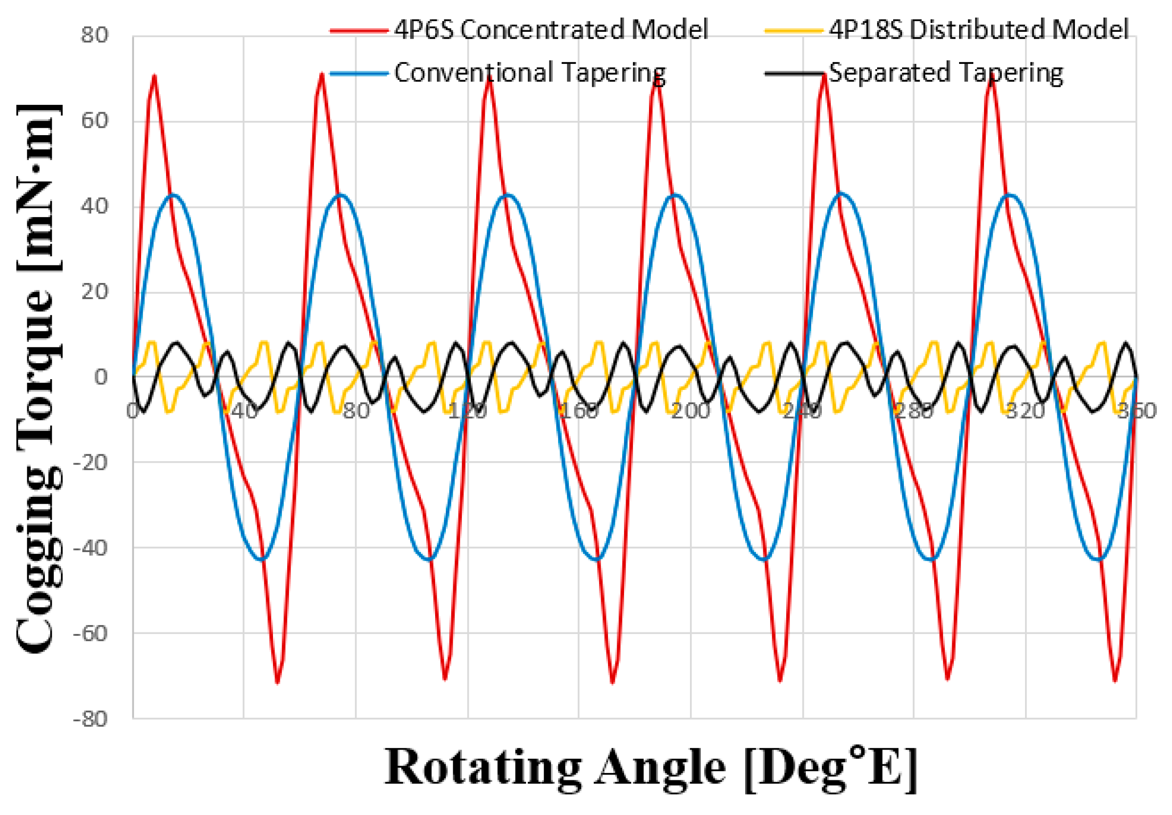
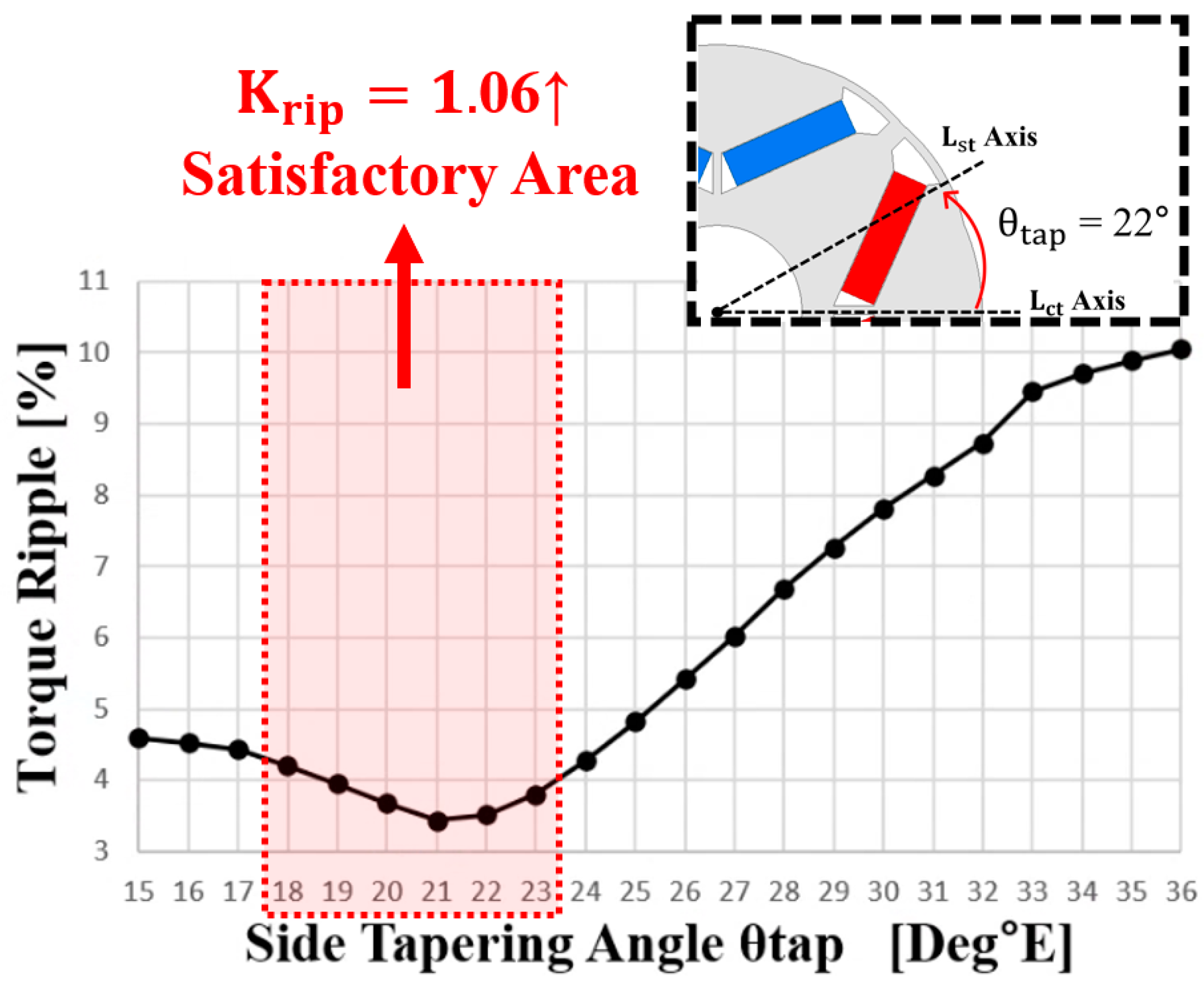
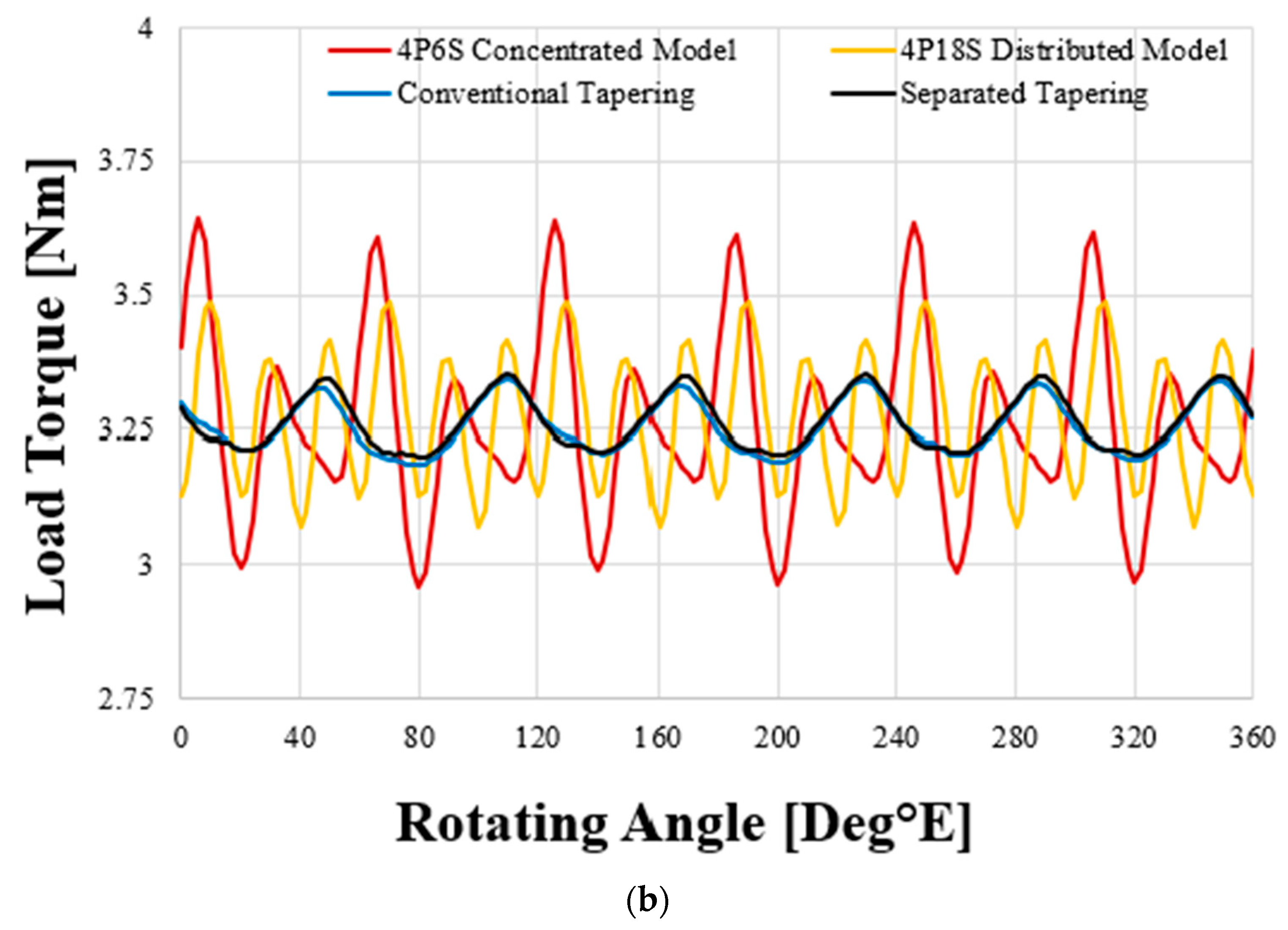
Figure 1 shows dry vacuum pump and motor for the semiconductor-ETCH (etching) process. The dry vacuum pump for the semiconductor-etching processes is a crucial component in semiconductor manufacturing. This specialized vacuum pump is designed to remove gases and particles from the etching chamber without introducing moisture or other contaminants. The dry vacuum pump operates without the need for oil or lubricants, making it suitable for cleanroom environments and critical semiconductor-fabrication processes. It uses advanced technologies such as scroll, claw, or turbomolecular mechanisms to create a vacuum within the etching chamber. This vacuum ensures the removal of unwanted byproducts and gases, maintaining a stable and controlled environment for precise etching processes. The absence of oil or lubricants in these pumps reduces the risk of contamination and outgassing, which can negatively impact the quality of semiconductor devices. Therefore, dry vacuum pumps play a vital role in enabling high-quality, high-precision semiconductor-etching processes, contributing to the production of advanced microelectronics. Therefore, in vacuum pumps used for etching processes that require high precision, minimizing vibration and noise is of paramount importance.
Figure 2 shows the design process for a motor with separated tapering. It looks like the general IPMSM process. However, the difference is the design of the tapering. A motor with a basic concentrated winding IPMSM can have a higher slot-fill factor than a distributed winding. However, concentrated windings are characterized by very high torque ripple. Concentrated winding has the fatal drawback of very high torque ripple, which is difficult to control and may prevent smooth operation. However, by applying tapering to the rotor and stator to make the magnetic flux flow sinusoidal and designing the iron core to shave off unnecessary saturation areas, the torque ripple can be lowered and iron loss can be reduced. Therefore, after the basic design for the motor size in Figure 2, it is necessary to apply tapering to the rotor and stator, respectively, and compare the tendencies. Torque-ripple targets for tapering length selection in the process were targeted with Model 1. After determining the tapering lengths Lct and Lst, the stator was tapered to match the rotor geometry. The rotor and stator were shaped to minimize the torque ripple. Finally, θtap was determined and Model 4 was derived, which has very low cogging torque and torque ripple compared with the other models.
Figure 3 shows a concentrated winding model (Model 1), distributed winding model (Model 2), conventional tapering model, and separated tapering model. Figure 3 shows the parameters for separated tapering of the rotor. Applying separated tapering of the rotor can reduce the change in reluctance in the air gap, which reduces cogging torque, torque ripple, and losses. The design was changed from basic distributed winding (Model 2) to concentrated winding (Model 1). Concentrated winding can wind more coils on the stator teeth than distributed winding. It is also easy to manufacture and very advantageous for mass production. Concentrated winding is also very practical and easy to manufacture due to the short Turnend of the coils, which is not an area of motor performance. However, concentrated winding has the disadvantage of higher torque ripple than distributed winding. These problems can be solved by tapering the rotor and stator to make the airgap magnetic flux sinusoidal.
Figure 4a,b show a design for a separated tapering rotor. The typical rotor tapering is created by Lct, as shown in Figure 4. However, this paper introduces a new tapering axis called Lst, which takes the form of two arcs with the axis divided into two axes. If tapering is performed only on the existing Lct, it is applied even to areas where tapering is not required. However, in the case of the method in Figure 4, a design can be created that incorporates all the advantages of the conventional method along with new advantages. This tapering method in which Lst and Lct, are applied simultaneously is defined as separated tapering. The reason for separating the axis into two on both sides is explained below [2,3].
Figure 5 shows the process where magnets are pushed inside the rotor during conventional tapering. The reason for dividing the axis into two is explained in Figure 5. In the conventional tapering method, as shown in Figure 4b, where only Lct is considered, increasing the value of Lct for greater tapering effect necessitates pushing the magnets inside the rotor, which maintains the shape of the permanent magnets on the rotor. When the permanent magnets are pushed inside the rotor, it results in tapering that affects the output because it moves away from the air gap. However, with the application of separated tapering, an additional Lst axis is added on both sides to secure the ends of the permanent magnets in place. This allows tapering of only the rotor pole-piece side when tapering the rotor, without affecting the geometry of the permanent magnets, thus preventing degradation of motor output. Tapering the outer surface of the rotor without affecting the position and shape of the permanent magnets is necessary to minimize the reduction in motor output power. Additionally, since cogging torque and torque ripple can be influenced by changes in rotor geometry, tapering is required to minimize cogging torque and torque ripple.
Figure 6a defines parameters for the angle between the two axes, Lst and Lct. Figure 6b shows the rotor shape according to the separated axis angle. After separating the two axes, if the rotor can be finely designed according to the angle between them, it can have a significant effect in terms of cogging torque and torque ripple. In conjunction with the rotor to which separated tapering is applied as follows, conventional tapering is also applied to the stator. This maximizes the reduction of shape-sensitive cogging torque and torque ripple. The optimized design of the rotor was completed according to the θtap angle.
Figure 7 shows the stator tapering parameters. For motors with stator teeth, the change in magnetic reluctance is not constant as the rotor rotates with time. Since the change in magnetic reluctance is not constant, it is necessary to taper the unnecessary parts in the stator tooth structure. The stator shoe portion of the stator teeth was tapered with Lcf, θcf, and θsf parameters to match the geometry of the rotor. The rotor pole-piece tapering was designed to take the starting point according to the length of Lcf only in the area where the tapering was applied and taper it by the stated angle. Lcf is determined within half of the stator teeth, and θcf tapers the unnecessary area of the stator teeth.
This allows the magnetic flux emitted from the permanent magnets to be concentrated by the rotor tapering and by the stator tapering, and the magnetic flux is concentrated on the stator teeth. This design prevents leakage flux as much as possible and obtains a sinusoidal magnetic flux flow. In addition, the design does not affect the permanent magnets and does not cause reduction in output power.
Figure 8a shows the airgap magnetic flux density (airgap B) for the conventional model (Model 1) and the separated tapering model (Model 4), while (b) shows the harmonic distortion (THD) of the no-load line voltage by harmonic order. In (b), it can be observed that in Model 1, the fundamental component is naturally slightly larger, but there are significant increases in the 5th, 7th, 11th, and 13th harmonic components. The final model, Model 4, exhibits significantly reduced harmonics compared to the conventional Model 1, with the THD decreasing from 11.71% to 3.84%. THD stands for total harmonic distortion, and a higher THD value indicates that there are more harmonic components in the voltage waveform, signifying greater distortion from the ideal sinusoidal waveform. When harmonics distort the voltage waveform, it reduces stability. As a result, the significant reduction in THD observed in Model 4 indicates its improved stability and reliability compared with Model 1.
The final model was selected based on Krip values at two points, with a rated speed of 6600 rpm and a maximum speed of 9000 rpm. The existing concentrated winding model had a significant drawback, which was high torque ripple. To address this issue, this paper proposes a method to reduce torque ripple and mitigate the critical shortcomings of the existing rotor torque ripple. In this proposed approach, a new concept called “rotor separated tapering” is introduced, which can prevent output degradation and further reduce torque ripple. To complement the separated tapering of the rotor, the stator teeth are also tapered to drastically reduce torque ripple. This reduction in torque ripple is expected to minimize vibrations and noise not only at the rated speed but also at the maximum speed. Furthermore, tapering reduces the magnetic flux of the permanent magnets, allowing the center point known as the “M-point” of the voltage-limit locus to fall within the current limit area. This design offers significant advantages, especially for high-speed motor applications. It is also easy to manufacture, making it a groundbreaking production method for the electric motor industry. The design process was carried out based on the results data provided below.

4. Results

4.1. Data Analysis with Tapering Parameters

Table 1 presents the four-pole six-slot motor parameters for a 3 kW ETCH process. The final model was selected and data were analyzed at a rated speed of 6600 rpm. Additionally, a two-point design was conducted at 6600 rpm and 9000 rpm as part of the high-speed design process. While the rated operating speed is 6600 rpm, it is important to note that the instantaneous maximum speed can reach up to 9000 rpm. Therefore, a high-speed design was carried out to optimize performance at 9000 rpm. At the rated speed, the output is 4.45 Nm for a 3 kW motor. As explained earlier, the teeth-concentrated model was chosen for mass production. The rotor’s permanent magnet is N42UH, a neodymium magnet, and the core material is 30PNF1600. The motor’s total outer size diameter is 100 mm, and the lamination was designed at 45 mm.
Figure 9 shows how the mesh settings were analyzed; the airgap mesh was divided very finely, and the data were analyzed in detail. More accurate data can be obtained when the mesh is analyzed by dividing the mesh into smaller pieces for the areas to be focused on. Since cogging torque and torque ripple are rotor- and stator-shape-sensitive, the mesh in the critical areas was finely divided to induce accurate analysis. The analysis was conducted using the 3D finite element analysis (FEA) capability of Ansys Maxwell 23.R2 software, with a total of 1,317,946 spatial elements, as shown in Figure 9. The specific area of interest in the motor, which requires a detailed analysis, is the air gap between the rotor and stator. Therefore, the number of elements in the air gap was divided into 601,250 elements. In Figure 9, each grid cell represents one spatial element.
Figure 10 shows the cogging torque waveform at the rated speed of 6600 rpm. All four models were analyzed for data comparison, and finally, Model 1 was improved and designed into Model 4 to reduce the cogging torque by 88.18%. Figure 10 shows that the cogging torque is very low, at a level comparable to distributed windings. The final model was designed to reduce cogging torque at the rated operating speed of 6600 rpm. Since cogging torque is one of the causes of torque ripple, it is necessary to observe the trend of torque ripple while reducing the cogging torque. For this reason, the following data on torque ripple were analyzed [16,17,19,22].
Figure 11 shows the relationship between torque ripple parameters and side tapering length. To minimize torque ripple, which is the primary objective in separated tapering, it is essential to find an optimal value that reduces torque ripple due to tapering length. Before determining this optimum value, certain factors need to be considered. The following are some of the considerations considered prior to selection [2,3,5,7,8].
Considering the stiffness and the conventional model analysis with a tapering length of 5 mm, the optimal lengths of Lct and Lst were chosen by selecting an area where the primary torque ripple target was less than 9.2%. θtap was analyzed with a temporary angle of 32 degrees that satisfied the target torque of 4.4 Nm. This angle was selected before the final shape was determined [8,22,23]. The variations in the values of Lst and θtap resulted in slight fluctuations in the outcomes, but these subtle differences are not significant. When designing, it is important to select the value of Lst within the range that satisfies the target conditions, since the primary focus is on meeting the specified design criteria.
Table 2 shows the data for the ripple factor Krip. The ripple constant Krip is defined as the load torque divided by the torque ripple (Tripple). This design target was selected as a criterion so that Krip would be greater than 1.06. The target value for the ripple constant Krip, exceeding 1.06, is based on the rated speed of the conventional tapering model (Model 3) at 6600 rpm. The final model should be designed with a higher value of A than this. The angle range for θtap where Krip is greater than 1.06 was determined by FEA analysis to be between 18 and 23 degrees [2,3].
Figure 12 shows the changes in torque ripple rate according to the side tapering angle (θtap). The data were analyzed to minimize torque ripple without degrading the output power. When optimally designed with respect to the θtap angle, the results show a significantly lower torque ripple compared with the conventional model. Additionally, implementing such a tapering method on the rotor does not affect the size of the permanent magnet, thus avoiding a reduction in power output. In conventional tapering, the permanent magnet is pushed into the rotor, leading to a drop in output. To compensate for this, the current was increased by 1.1 A to match the output. The area satisfying the goal of the torque ripple constant Krip, as analyzed in Table 2, above, is intuitively depicted in Figure 12. Finally, an θtap angle was selected to achieve the target output, resulting in a reduction in torque ripple from 16.03% in the conventional model (Model 1) to 3.55%.

4.2. Comparison of Analysis Data at Two Operation Points of 6600 rpm and 9000 rpm

Figure 13a shows the load-line voltage waveforms, indicating that voltage limits are generally considered and satisfied in the motor designs. Figure 13b shows the torque comparison at the same output for the three models when operating at the rated operating speed of 6600 rpm. The load-line voltage waveform in Figure 13a is used to monitor voltage fluctuations. Analyzing the load-line voltage waveform is crucial for evaluating the performance and stability of the motor and confirming voltage limits. As can be observed in Figure 13a, the voltage is stable, and it satisfies the voltage limit conditions. When the torque variation (Tpk2pk) increases, it leads to an increase in torque ripple (Tripple), which can be a source of motor vibrations. Therefore, designing to minimize torque variation (Tpk2pk) is essential. The separated tapering model shows less variation in torque. If the torque fluctuates significantly when the motor is running, the torque ripple becomes large, and vibration and noise are generated. Therefore, a new concept of tapering was applied to optimize the design to reduce the range of variation in torque magnitude and reduce torque ripple.
Table 3 shows the data at 6600 rpm, the rated operating speed. It was specified that the design would proceed to reduce cogging torque and torque ripple, which are problems when changing from distributed to concentrated winding, by applying separated tapering (Model 4). As shown in Table 3, the cogging torque was reduced by 88.18%, from 142.44 mNm to 16.84 mNm, and the torque ripple was reduced by 77.85%, from 16.03% to 3.55%. The cogging torque was reduced not only in the existing model but also in the same pole-number distribution winding model, and the torque ripple was reduced by 68.64%, from 11.32% to 3.55%.
Figure 14a shows the load-line voltage waveforms, indicating that voltage limits are generally considered and satisfied in the motor designs. Figure 14b shows the load torque at 9000 rpm. For the load-torque waveform, the black line is the separated tapering model. When the motor operates at high speed, the torque ripple increases. The red line in the basic model shows that the amplitude of the waveform is larger than the rated speed. This means that the torque ripple has increased. However, in the separated tapering model, the amplitude of the load torque is not so large. This indicates that the torque-ripple-reduction design was successful even at the maximum speed of 9000 rpm by applying separated tapering to the rotor. This new concept of tapering is very effective in reducing torque ripple when designing motors for high speeds.
Table 4 shows an analysis of the 9000 rpm data. The final model, Model 4, was confirmed to meet the target value of Krip equal to or greater than 0.67 specified in Model 3, even at a maximum operating speed of 9000 rpm. Compared with the basic concentrated winding model (Model 1), the torque ripple was reduced by 78.29%, from 21.42% to 4.65%, and the efficiency was improved by 1.67%, from 93.08% to 94.64%. Thus, the separated tapering model (Model 4) is much more suitable in the high-speed operation area than the basic concentrated winding model (Model 1).
Figure 15a shows the efficiency map of Model 1, while Figure 15b displays the efficiency map of Model 4. The efficiency map allows us to intuitively see the efficiency according to rotating speed and torque. In the 6600~9000 rpm range from the rated operating speed to the maximum operating speed, it was confirmed that there was no problem, as in the below T-N curve analysis. Within the analyzed parameter range, Model 4 has an advantage at high speeds compared with Model 1. In Figure 15, the shaft torque represents the torque and considers losses such as copper loss, eddy current loss, iron loss, and so on in a PM motor. When comparing the same efficiency range in Figure 15a,b, it is intuitive to observe that Model 4, depicted in Figure 15b, exhibits higher efficiency from the rated operating speed of 6600 rpm up to the maximum operating speed of 9000 rpm, as evident from the efficiency map.
Figure 16a shows the current and voltage limits of the basic model (Model 1) and the separated tapering model (Model 4). Figure 16b shows the T-N curve comparison of the separated tapering model and the target model. Motors do not generate large, induced voltages in the low-speed range, and the voltage generated by the motor is often lower than the voltage that can be applied to the motor. When this is the case, control does not need to consider voltage limiting, only current limiting. This is MTPA control. However, in the speed range above the base speed, voltage limiting must be considered in addition to current limiting. The current vector is to be selected at the intersection where the voltage- and current-limit sources meet. The M point, the center of the current- and voltage-limit circle, is more favorable for higher speeds when it is near the center of the current-limit circle. The current- and voltage-limit circle for the separated tapering model is shown in Figure 16, and the center point M of the voltage-limit circle for the separated tapering model is inside the current-limit circle. This is because the rotor tapering has reduced the chain flux of the permanent magnet that determines the position of the M point. It can be seen in Figure 16 that the separated tapering model also has higher base torque than the target model and is more advantageous in the high-speed area. The voltage limit is applied at 6000 rpm for the target model, but at 8300 rpm for the separated tapering model. At an operating speed of 9000 rpm, the T-N curve shows that the separated tapering model is much higher, indicating that the separated tapering model has an advantage in operating in the high-speed range. Considering the maximum speed up to 9000 rpm, the design proceeded as follows [12,14].
Figure 17a shows radial B as a function of rotor position for the conventional model (Model 1) and the separated tapering model (Model 4), while Figure 17b shows the vibration velocity [m/s] with respect to spatial distribution. In Figure 17a, when compared with the conventional model, the radial B of spatial flux density is sinusoidal, and the magnitude of the radial force is lower. Radial force refers to the force generated in the radial direction as the rotor rotates away from the center. Electromagnetic vibrations are primarily caused by the spatial distribution of radial force over time. Since radial force is expressed as the square of airgap flux density, the spatial harmonics of airgap flux density affect the spatiotemporal harmonics of radial force. The larger the radial force, the greater the motor’s vibrations, leading to poor stability. The radial force of a motor can lead to vibration and noise issues, making control more challenging. Moreover, there is a significant safety risk when there is contact between the stator and rotor. In Figure 17a, Model 4 exhibits a more sinusoidal and stable waveform compared with Model 1, due to its lower radial force, and Figure 17b represents vibration velocity, showing the values of spatially distributed vibrations by harmonic order. It can be observed that Model 4 has an overall vibration value approximately 13.18% lower than Model 1 [14,18]. As seen in Figure 17, Model 4 has a lower radial force compared with Model 1, which results in lower vibration velocity in the motor.

4.3. Analysis of B Plots, and Demagnetization of Permanent Magnet Check

By concentrating the magnetic flux exiting the air gap as in the separated tapering model, the amount of magnetic flux received from the stator teeth increases. However, the amount of magnetic flux density that can be received by the thickness of the stator teeth is limited, and if the limit is exceeded, the teeth will become saturated. The saturation also affects the increase in iron loss, which causes heat generation and affects the overall performance. Therefore, it is important to consider the saturation of the stator teeth during the design process, and this is shown in Figure 18. As shown below, the saturation degree of the stator value is approximately 1.45 T, indicating that the design is sufficiently stable. Additionally, the stator back yoke is approximately 1.32 T and is extremely stable.
The demagnetization capability of the permanent magnet was confirmed for the improved design model, as shown in Figure 19. Demagnetization of the permanent magnets must be considered when designing electromagnetic fields; the IPMSM performs weak flux control at high speeds, and demagnetization phenomena may occur due to reverse magnetic fields. If the operating point is formed below the knee point in the B-H curve of the permanent magnet, the permanent magnet loses magnetism and demagnetization occurs. After demagnetization, even if the operating point is formed above the knee point again, the permanent magnet cannot return to the magnetic flux density it had before and has a lower flux density than before, which is called the irreversible demagnetization phenomenon. When a magnet is demagnetized, the magnetic flux density of the permanent magnet is affected, which in turn affects the performance of the motor. The next method of confirming demagnetization of a permanent magnet was to apply a current five times the rated current and confirm a demagnetization ratio of 0% for the permanent magnet. In addition, since NdFeB magnets have high-temperature demagnetization characteristics, the demagnetization ability of the permanent magnet was confirmed through 2D and 3D FEA analysis using B-H curve values of NdFeB magnets at 150 °C, considering extreme conditions at high temperatures.

5. Conclusions

This paper presents a new concept model of separated tapering to reduce cogging torque and torque ripple compared with the conventional concentrated model of a 3 kW semiconductor-ETCH-process vacuum pump motor. The design proceeded to reduce cogging torque and torque ripple according to the rotating angle of θtap. Since cogging torque and torque ripple are major causes of vibration and noise in motors, it is important to design motors used in vibration-sensitive semiconductor processes to reduce cogging torque and torque ripple. The final model with separated tapering (Model 4) was subjected to two-point design at a rated operating speed of 6600 rpm and a maximum operating speed of 9000 rpm. The reduction in torque ripple was confirmed for both rated and maximum speeds. The cogging torque and torque ripple of the basic concentrated model (Model 1) and the separated tapering model (Model 4) were compared and analyzed through finite element analysis (FEA). At the rated rotating speed of 6600 rpm, the cogging torque was reduced by 88.18% from 142.44 mNm in the conventional model to 16.84 mNm, and the torque ripple was reduced by 77.85% from 16.03% to 3.55%. At a maximum rotating speed of 9000 rpm, the torque ripple was reduced by 77.85%, from 16.03% in the conventional model to 3.55%, and the overall vibration, as a result of torque-ripple reduction, decreased by 13.18%. The final proposed model (Model 4) includes an innovative separated tapering design that minimizes cogging torque and torque ripple while also being advantageous at high speeds.

Author Contributions

Conceptualization, W.-H.K.; methodology, D.-H.C.; software, M.-K.H.; validation, D.-H.C.; formal analysis, I.-J.Y.; investigation, I.-J.Y.; resources, D.-H.C.; data curation, D.-H.C.; writing—original draft preparation, D.-H.C.; writing—review and editing, M.-K.H. and D.-H.J.; visualization, D.-H.C. and D.-H.J.; supervision, W.-H.K. All authors have read and agreed to the published version of the manuscript.

Funding

This research was partly supported by the Korea Institute of Energy Technology Evaluation and Planning (KETEP) grant funded by the Korea government (MOTIE) (20214000000060, Department of Next Generation Energy System Convergence based on Techno-Economics STEP) and in part by the Gachon University research fund of 2021 (GCU-202110130001).

Data Availability Statement

Not applicable.

Conflicts of Interest

The authors declare no conflict of interest.

References

  1. Xu, J.; Zhang, L.; Meng, D.; Su, H. Simulation, Verification and Optimization Design of Electromagnetic Vibration and Noise of Permanent Magnet Synchronous Motor for Vehicle. Energies 2022, 15, 5808. [Google Scholar] [CrossRef]
  2. Alharkan, H. Torque Ripple Minimization of Variable Reluctance Motor Using Reinforcement Dual NNs Learning Architecture. Energies 2023, 16, 4839. [Google Scholar] [CrossRef]
  3. Lee, M.; Hwang, Y.; Nam, K. Torque Ripple Minimizing of Uniform Slot Machines with Delta Rotor via Subdomain Analysis. Energies 2021, 14, 7390. [Google Scholar] [CrossRef]
  4. Qu, C.; Guo, Z.; Hu, Y.; Wang, X.; Han, F. Multi-Objective Optimization Design of a New Permanent Magnet Synchronous Motor Based on the Taguchi Method. Energies 2022, 15, 7347. [Google Scholar] [CrossRef]
  5. Caruso, M.; Di Tommaso, A.O.; Miceli, R.; Viola, F. A Cogging Torque Minimization Procedure for Interior Permanent Magnet Synchronous Motors Based on a Progressive Modification of the Rotor Lamination Geometry. Energies 2022, 15, 4956. [Google Scholar] [CrossRef]
  6. Tao, X.; Takemoto, M.; Tsunata, R.; Ogasawara, S. Novel Rotor Structure Employing Large Flux Barrier and Disproportional Airgap for Enhancing Efficiency of IPMSM Adopting Concentrated Winding Structure. IEEE Access 2023, 11, 2848–2862. [Google Scholar] [CrossRef]
  7. Lee, C.-S.; Kim, H.-J. Harmonic Order Analysis of Cogging Torque for Interior Permanent Magnet Synchronous Motor Considering Manufacturing Disturbances. Energies 2022, 15, 2428. [Google Scholar] [CrossRef]
  8. Akiki, P.; Hassan, M.H.; Bensetti, M.; Dessante, P.; Vannier, J.C.; Prieto, D.; McClelland, M. Multiphysics Design of a V-Shape IPM Motor. IEEE Trans. Energy Convers. 2018, 33, 1141–1153. [Google Scholar] [CrossRef]
  9. Egorov, D.; Petrov, I.; Pyrhönen, J.J.; Link, J.; Stern, R.; Sergeant, P.; Sarlioglu, B. Hysteresis Loss in NdFeB Permanent Magnets in a Permanent Magnet Synchronous Machine. IEEE Trans. Ind. Electron. 2022, 69, 121–129. [Google Scholar] [CrossRef]
  10. Hwang, S.-W.; Lim, M.-S.; Hong, J.-P. Hysteresis Torque Estimation Method Based on Iron-Loss Analysis for Permanent Magnet Synchronous Motor. IEEE Trans. Magn. 2016, 52, 8204904. [Google Scholar] [CrossRef]
  11. Liu, G.; Liu, M.; Zhang, Y.; Wang, H.; Gerada, C. High-Speed Permanent Magnet Synchronous Motor Iron Loss Calculation Method Considering Multiphysics Factors. IEEE Trans. Ind. Electron. 2020, 67, 5360–5368. [Google Scholar] [CrossRef]
  12. Yamazaki, K.; Seto, Y. Iron loss analysis of interior permanent-magnet synchronous motors-variation of main loss factors due to driving condition. IEEE Trans. Ind. Appl. 2006, 42, 1045–1052. [Google Scholar] [CrossRef]
  13. Yamazaki, K.; Kumagai, M.; Ikemi, T.; Ohki, S. A Novel Rotor Design of Interior Permanent-Magnet Synchronous Motors to Cope with Both Maximum Torque and Iron-Loss Reduction. IEEE Trans. Ind. Appl. 2013, 49, 2478–2486. [Google Scholar] [CrossRef]
  14. Yamazaki, K.; Ishigami, H. Rotor-Shape Optimization of Interior-Permanent-Magnet Motors to Reduce Harmonic Iron Losses. IEEE Trans. Ind. Electron. 2010, 57, 61–69. [Google Scholar] [CrossRef]
  15. Kim, K.-C.; Jeon, S.-H. Analysis on Correlation Between Cogging Torque and Torque Ripple by Considering Magnetic Saturation. IEEE Trans. Magn. 2013, 49, 2417–2420. [Google Scholar] [CrossRef]
  16. Dosiek, L.; Pillay, P. Cogging Torque Reduction in Permanent Magnet Machines. IEEE Trans. Ind. Appl. 2007, 43, 1565–1571. [Google Scholar] [CrossRef]
  17. Seo, J.H.; Choi, H.S. Cogging Torque Calculation for IPM Having Single Layer Based on Magnetic Circuit Model. IEEE Trans. Magn. 2014, 50, 8102104. [Google Scholar] [CrossRef]
  18. Hwang, S.M.; Eom, J.B.; Hwang, G.B.; Jeong, W.B.; Jung, Y.H. Cogging torque and acoustic noise reduction in permanent magnet motors by teeth pairing. IEEE Trans. Magn. 2000, 36, 3144–3146. [Google Scholar] [CrossRef]
  19. Lukaniszyn, M.; Jagiela, M.; Wrobel, R. Optimization of permanent magnet shape for minimum cogging torque using a genetic algorithm. IEEE Trans. Magn. 2004, 40, 1228–1231. [Google Scholar] [CrossRef]
  20. Abbaszadeh, K.; Alam, F.R.; Teshnehlab, M. Slot opening optimization of surface mounted permanent magnet motor for cogging torque reduction. Energy Convers. Manag. 2012, 55, 108–115. [Google Scholar] [CrossRef]
  21. Liu, T.; Huang, S.D.; Gao, J.; Lu, K.Y. Cogging torque reduction by slot-opening shift for permanent magnet machines. IEEE Trans. Magn. 2013, 49, 4028–4031. [Google Scholar] [CrossRef]
  22. Koh, C.S.; Seol, J.S. New cogging-torque reduction method for brushless permanent-magnet motors. IEEE Trans. Magn. 2003, 39, 3503–3506. [Google Scholar]
  23. Bianchi, N.; Bolognani, S. Design techniques for reducing the cogging torque in surface-mounted PM motors. IEEE Trans. Ind. Appl. 2002, 38, 1259–1265. [Google Scholar] [CrossRef]
  24. Bianchini, C.; Immovilli, F.; Lorenzani, E.; Bellini, A.; Davoli, M. Review of design solutions for internal permanent-magnet machines cogging torque reduction. IEEE Trans. Magn. 2012, 48, 2685–2693. [Google Scholar] [CrossRef]
  25. Islam, R.; Husain, I.; Fardoun, A.; McLaughlin, K. Permanent-magnet synchronous motor magnet designs with skewing for torque ripple and cogging torque reduction. IEEE Trans. Ind. Appl. 2009, 45, 152–160. [Google Scholar] [CrossRef]
  26. Ishikawa, T.; Slemon, G.R. A method of reducing ripple torque in permanent-magnet motors without skewing. IEEE Trans. Magn. 1993, 29, 2028–2031. [Google Scholar] [CrossRef]
Figure 1. Dry vacuum pump and motor for semiconductor-ETCH process.
Machines 11 00991 g001
Figure 2. Process for the detailed design of 4P6S concentrated winding motor with separated tapering.
Machines 11 00991 g002
Figure 3. 2D models of the four motors used in the comparative analysis.
Machines 11 00991 g003
Figure 4. Rotor tapering parameters, (a) side tapering length, (b) center tapering length.
Machines 11 00991 g004
Figure 5. Problems with magnets being pushed and embedded in conventional tapering.
Machines 11 00991 g005
Figure 6. (a) Tapering in the Lct and Lst axes, and the angle between them, θtap (b) changes in the rotor shape with variations in θtap.
Machines 11 00991 g006
Figure 7. Stator tapering parameters.
Machines 11 00991 g007
Figure 8. (a) Airgap magnetic flux density for Model 1 and Model 4, (b) THD for Model 1 and Model 4.
Machines 11 00991 g008
Figure 9. Mesh setting for 3D FEA (finite element analysis).
Machines 11 00991 g009
Figure 10. 6600 rpm cogging torque.
Machines 11 00991 g010
Figure 11. Variation of torque ripple with tapering length.
Machines 11 00991 g011
Figure 12. Analyzing torque ripple as a function of θtap angle.
Machines 11 00991 g012
Figure 13. (a) 6600 rpm load-line voltage, (b) 6600 rpm load torque data.
Machines 11 00991 g013
Figure 14. (a) 9000 rpm load-line voltage, (b) 9000 rpm load torque.
Machines 11 00991 g014aMachines 11 00991 g014b
Figure 15. (a) Model 1 efficiency map, (b) Model 4 (separated tapering) efficiency map.
Machines 11 00991 g015
Figure 16. (a) Current- and voltage-limit circle, (b) T-N curve.
Machines 11 00991 g016
Figure 17. (a) Radial B for Model 1 and Model 4, (b) vibration velocity for Model 1 and Model 4.
Machines 11 00991 g017
Figure 18. Separated tapering 3D-model B plot.
Machines 11 00991 g018
Figure 19. Magnetization and demagnetization of permanent magnet: 2D and 3D analysis.
Machines 11 00991 g019
Table 1. 4P6S motor parameters for a 3 kW ETCH process.
ParameterValueUnit
Poles/Slots
Speed
Current
4/6-
6600~9000RPM
11~18.4Arms
Rated power
Rated torque
3kW
4.45N·m
Airgap length0.5mm
Stator diameter (inner, outer)25.5, 50mm
Rotor diameter (inner, outer)8, 25mm
Stack length45mm
Core30PNF1600
MaterialPermanent magnetN42UH
CoilCopper
Table 2. 6600 rpm FEA analysis results for the ripple factor Krip.
θtapLoad Torque
Tavg (Nm)
TrippleKrip
(Torque/Tripple)
154.49264.589770.978829
164.48984.5302690.991067
174.48674.4308731.012599
184.48334.2022621.066878
194.47863.9498951.133853
204.47363.6838341.214387
214.46883.441641.298451
224.4643.5215051.26764
234.45823.8064691.171217
244.4514.2799371.039969
254.44634.8197380.922519
264.44025.4209270.819085
274.43286.0300490.735118
284.42636.689560.661673
294.42087.2701770.608073
304.41397.8162170.564711
314.40668.2671450.533026
324.40118.7273640.504287
334.41939.4562490.467342
344.41419.7007320.455028
354.40869.8829560.446081
364.404910.043360.438588
Table 3. 6600 rpm Final Data Analysis.
ParameterBasic Concentrated Winding Model (Model 1)Distributed Winding Model (Model 2)Conventional Tapering Model (Model 3)Final Separated Tapering Model (Model 4)
Cogging torque (mNm)142.4416.26176.1716.84
Load torque (Nm)4.494.444.454.46
Torque ripple (%)16.0311.324.23.55
Krip0.280.391.061.26
L2L + IR (Vmax)238.97216.73224.22228.02
Current (A)13.414.219.518.4
Current density (A/mm2)8.539.4212.3511.71
Output power (kW)3.013.013.033.04
Table 4. 9000 rpm Final Data Analysis.
ParameterBasic Concentrated Winding Model (Model 1)Distributed Winding Model (Model 2)Conventional Tapering Model (Model 3)Final Separated Tapering Model (Model 4)
Load torque (Nm)3.263.273.263.26
Torque ripple (%)21.4212.854.834.65
Krip0.150.250.670.7
L2L + IR (Vmax)277.23257.22252.54263.76
Current (A)9.710.411.711
Current density (A/mm2)6.176.97.457
Output power (kW)2.993.053.023.01
Disclaimer/Publisher’s Note: The statements, opinions and data contained in all publications are solely those of the individual author(s) and contributor(s) and not of MDPI and/or the editor(s). MDPI and/or the editor(s) disclaim responsibility for any injury to people or property resulting from any ideas, methods, instructions or products referred to in the content.

