1. Introduction
The ongoing digitalization of processes and products in mechanical engineering serves to implement control tasks, condition monitoring and predictive maintenance, to increase productivity, and establish new business models [
1,
2]. A basis for this is the availability of usable data of sufficient quality and quantity. A wide variety of sensors can be used for data acquisition. However, the requirements that must be met by the sensor solutions are also continuously increasing [
3]. For example, additional installation space required for sensor and auxiliary elements must be kept to a minimum. The sensor solution should also have as little negative impact as possible on the technical system; e.g., due to component weakening, and should also be as robust as possible in regard to potential disturbance variables. The complexity must also be kept to a manageable level; e.g., by using standardized electrical and mechanical interfaces. In addition to these requirements, there are many more, but a focus on these is sufficient to motivate this contribution.
One technical possibility for implementing highly integrated sensory functions are so-called mechatronic machine elements [
4]. Sensing machine elements are derived from mechatronic machine elements [
5]. These are conventional and standardized machine elements which are extended by one or more sensory functions with as few modifications as possible. On one hand, the sensor and auxiliary elements can be integrated on or in the machine element. On the other hand, it may also be possible to use the electrical properties of the machine element in operation directly in a sensory manner—so-called sensory utilizable machine elements (SuME). One example of this innovative approach are sensory utilizable gears that are subject to ongoing research activities; e.g., [
6,
7,
8]. The impedance of the gear mesh, which is directly dependent on the lubrication condition and the proportion of mixed friction [
9,
10], is to be used to derive conclusions regarding rotational speed, acting torque, and potentially surface damage. Another example are sensory utilizable rolling element bearings that have been subject to research activities for many years—e.g., [
11,
12,
13,
14,
15]—and are currently being brought to production maturity in the industry; e.g., [
16]. As shown in
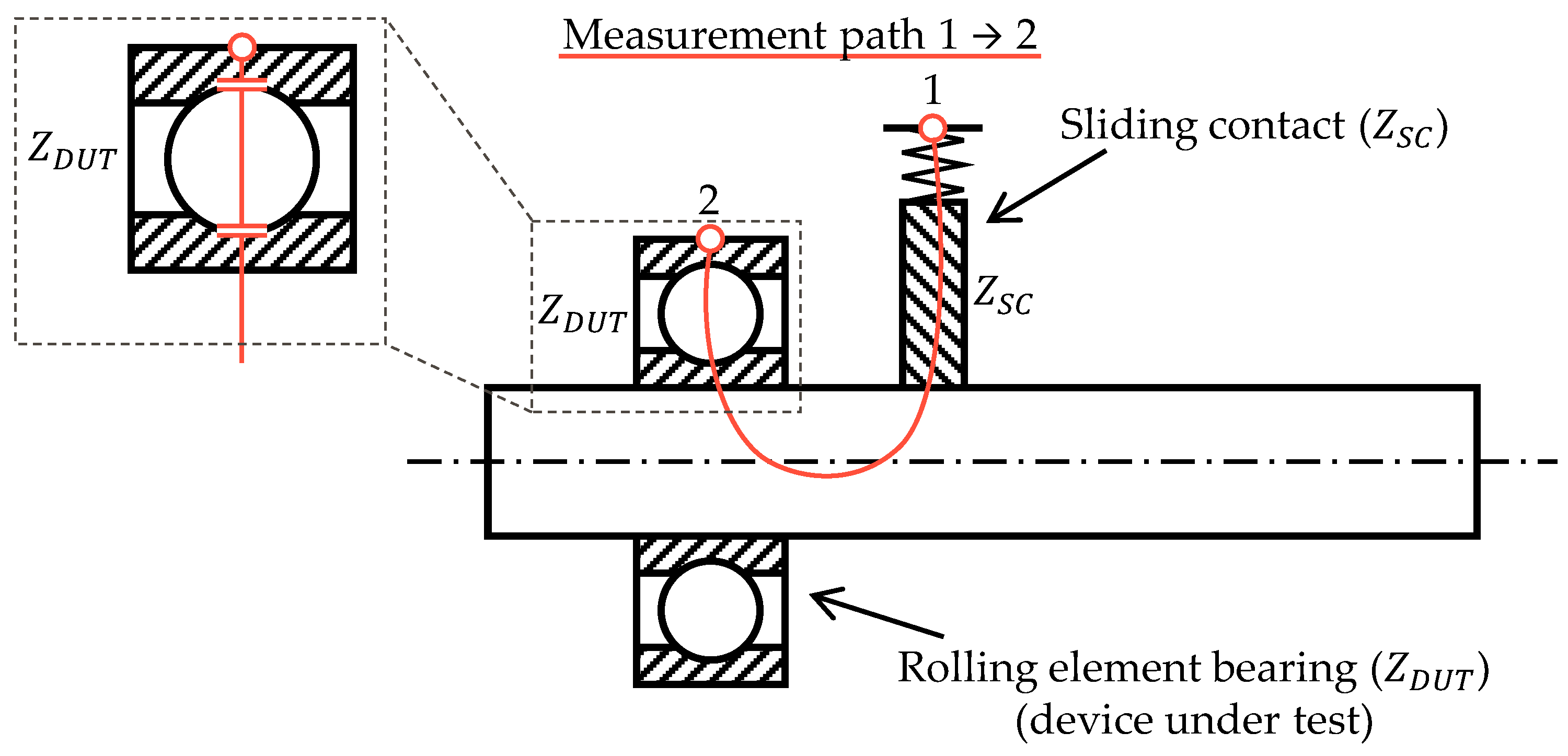
Figure 1, the electrical capacitance of a rolling element bearing is measured—e.g., by a suitable impedance measurement of
—and used for sensory purposes on the basis of the relationship between lubrication film thickness and capacitance. Due to their influence on the lubrication film thickness, conclusions can be drawn about acting loads, applied rotational speeds, present temperatures, or even damages in the raceways.
Since additional elements for energy supply and storage as well as for signal processing and transmission are omitted as far as possible in case of SuME, the actual development of SuME represents only a part of current challenges. If SuME are to be integrated into or onto rotating systems—e.g., on a shaft—as is the case with sensory utilizable gears and rolling element bearings, two main questions arise in addition to the actual development of the sensory function:
At the moment, sliding contacts are often used for test rigs and applications of SuME on rotating systems; e.g., [
6,
7,
8,
12,
13,
14,
15]. These are specialized elements, such as carbon or steel brushes, which are pressed onto the rotating element by means of—e.g., a preloaded spring. In this way, uniform and interruption-free electrical contacting can be achieved. As can be seen in
Figure 1, this electrical contacting approach represents a part of the measurement path from contact point 1 to contact point 2 of SuME. The measured impedance thus consists of the impedance of the device under test (DUT)
, and connected in series, the impedance of the sliding contact
.
In order to measure the capacitance of the rolling element bearing in operation, the stationary outer ring and the rotating inner ring must be electrically contacted. Thus, not only is the capacitance of the rolling element bearing measured, but also the electrical properties of the sliding contact, which contacts the rotating shaft near the inner ring. Commonly used compensation approaches to eliminate the cable and contacting impedances from the measured impedance cannot be applied in these experimental setups without constructive modifications. Such necessary modifications would limit the general usability and the possibility of retrofit solutions for SuME.
Although sliding contacts are described extensively in the literature—e.g., [
17,
18]—and used in both research and industrial practice, there is still no comprehensive understanding of their influence on impedance measurements in the context of SuME. Despite initial studies of the electrical behavior of sliding contacts in this context [
19,
20], random sliding contacts are often selected for test setups without having systematically chosen a suitable solution; e.g., [
6,
7,
8,
12,
13,
14,
15]. Thus, sliding contacts in applications differ by the material used, the relative contact position to the rotating element, and other parameters. The aim of this contribution is to systematically investigate and qualitatively describe the influences of sliding contacts on impedance measurements in the context of SuME. For this purpose, a suitable experimental setup is designed in which sliding contacts of different materials can be examined at different rotational speeds and in different relative positions to the rotating element. These factors are then varied at two levels each, and the resulting effects on the measurable impedance are evaluated and discussed. The aim is to gain an understanding of the conditions under which sliding contacts can be used in the context of impedance measurements for SuME, how the influence on the measurable impedance may look, and how potential influences can be controlled.
2. Materials and Methods
As already described in the previous section, potential effects of three identified factors on the electrical impedance of sliding contacts are to be systematically investigated. The factors to be considered are the material, the rotational speed of the shaft, and the relative positioning of the sliding contacts to the rotating shaft, as these are variable factors in SuME applications. In a first screening experiment, potential effects on the impedance are to be identified and examined for significance in accordance with design of experiment approaches, and using the analysis of variance method ANOVA [
21]. The ANOVA is performed with the help of suitable functions of the ‘Statistics and Machine Learning Toolbox’ for the software
Matlab R2023a [
22]. For this screening purpose, the three factors mentioned are varied according to
Table 1 on two levels each. Graphite and silver graphite carbon brushes from Josef Mack GMBH & Co. KG (Grünberg, Germany) are used as materials [
23]. These are common materials, which therefore form a suitable basis for initial experiments. The rotational speed of the shaft is varied at levels of 500 rpm and 2000 rpm. The corresponding sliding speeds for the radii used are given in
Table 1. This gives an overview of a typical rotational speed range in which there is still minimal risk of the carbon brushes lifting off. Special applications with very high rotational speeds, such as tool spindles, would be associated with significantly higher requirements on the experimental setup, as well as the sliding contacts, and are therefore not considered. The position of the sliding contact can be in axial as well as radial directions. The carrier frequency typically depends on the application. Through preliminary tests at the institute, the value of the carrier frequency for these experiments was set to a constant 100 kHz.
The three factors described above are investigated in a target-oriented two-stage full-factorial experimental design. Due to the feasible effort of a full-factorial design, a fractional factorial design is not used. Each factor level combination is independently set and measured three times for 2 s each. After setting a factor level, the experimental setup runs for 5 min under the set operating conditions before the measurement is performed. This also applies if the operating conditions should not change. In this case, a waiting time of 5 min between measurements is maintained with the set operating conditions. In order to reduce the probability of systematic errors, the experiments are performed in a randomized order. The randomization was performed with the help of an online random number generator [
24]. Due to the high effort of switching between axial and radial contacting, axial and radial tests are performed in separate blocks. However, within these blocks, the previously mentioned randomization takes place. The resulting test sequence used in the screening design is listed in
Table 2. The results of this series of experiments are given in
Section 3.2.
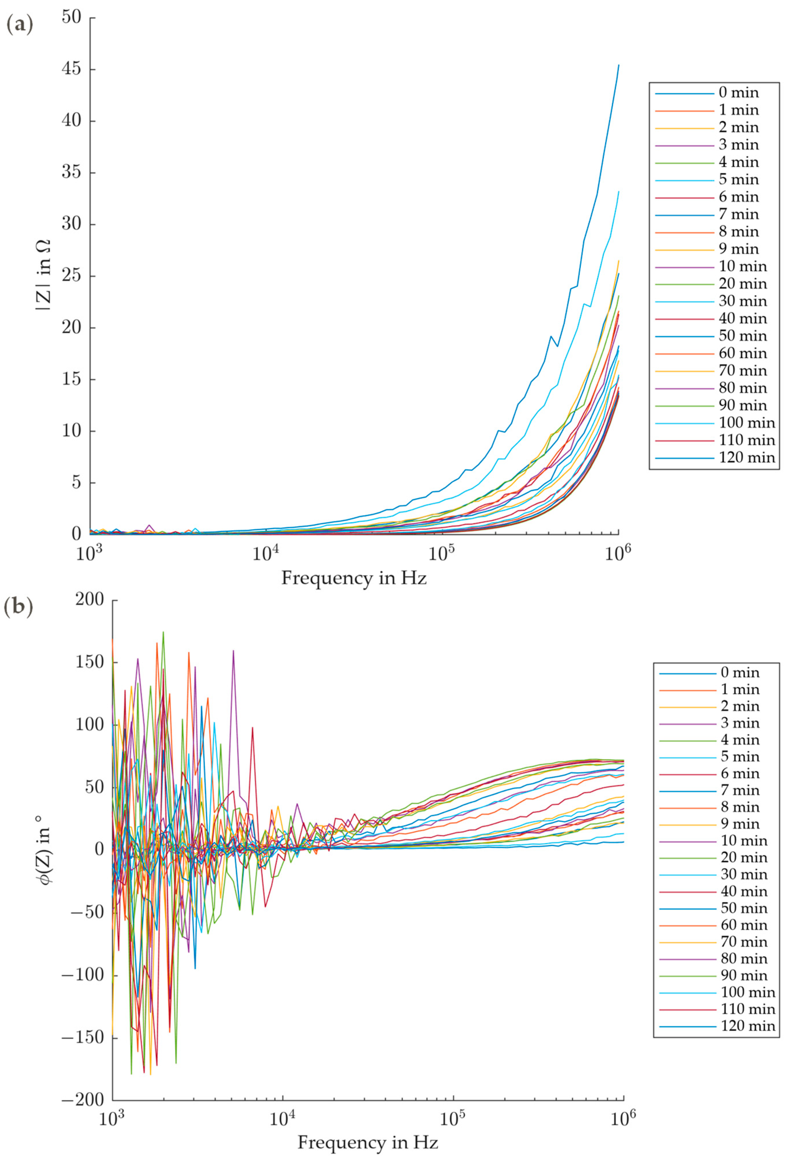
Since a specific value of 100 kHz for the carrier frequency is defined for the first experimental series, but in practice this must be selected for a specific application, various carrier frequencies are investigated in the second experimental series. In order to keep the experimental effort manageable, a constant operating point with appropriate impedance values (see
Section 3.2) is selected: Silver graphite carbon brush in axial position at 500 rpm. The carrier frequency is swept in a range from 1 kHz to 1 MHz. In addition, the runtime-dependent behavior is to be investigated; therefore, the frequency sweeps are repeated at regular intervals over a total period of 120 min. The results for this series of experiments are given in
Section 3.3.
A suitable experimental setup was designed and built for the experimental investigation. With this setup, potential effects of different materials, positions, and rotational speeds on the impedance can be analyzed.
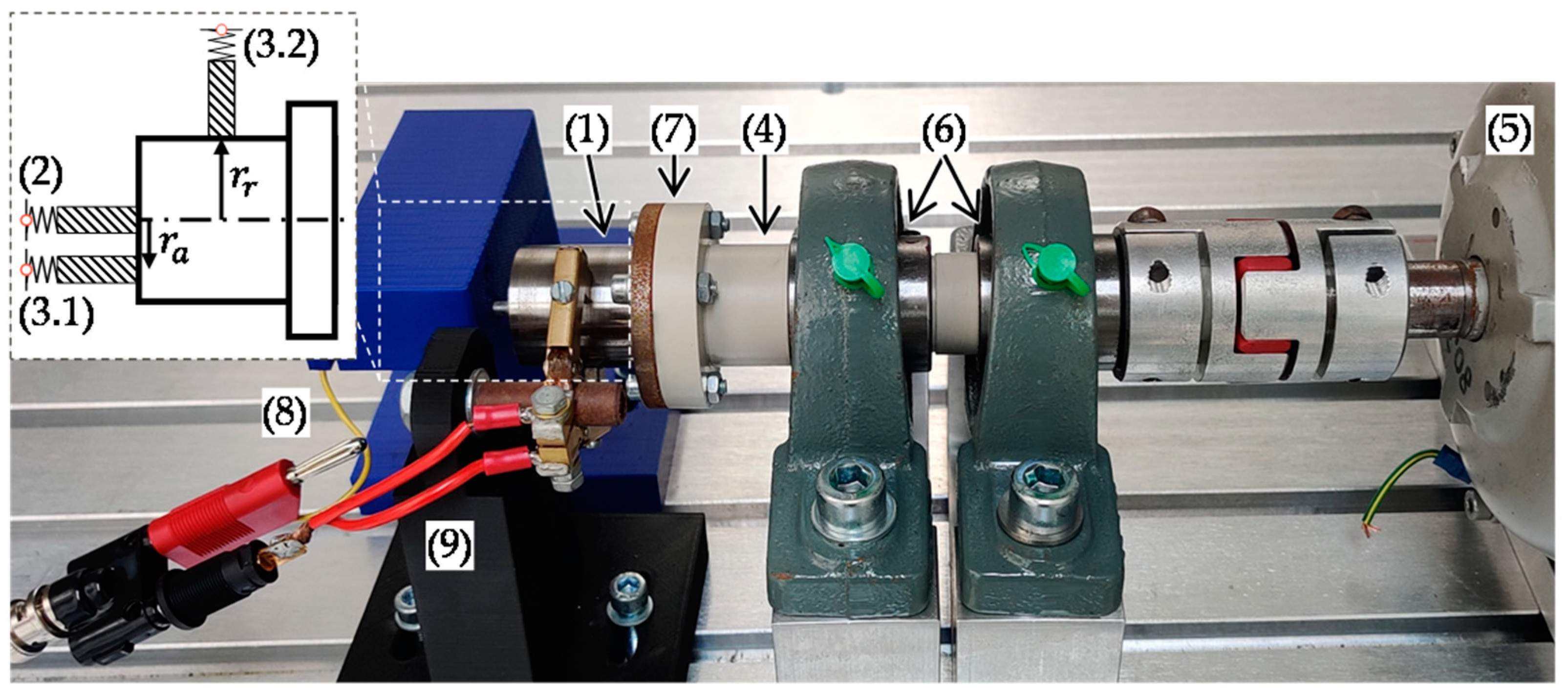
Figure 2 shows the complete experimental setup. On the left side, a steel shaft (1) with a diameter of 30 mm is electrically contacted by two carbon brushes. A fixed reference contact point is always located in the rotational axis on the face of the shaft (2), and is not changed during the experiments. A silver graphite carbon brush is used as a reference. The second contact position can either be slightly offset on the shaft face (3.1, axial contact,
), or on the lateral surface of the shaft (3.2, radial contact,
). This way, there is always a measurement path over two sliding contacts, with the variable contact position representing a factor as described above. The main shaft (4), which is made of polypropylene, is driven by an electric motor (5) and can be adjusted to various speeds. The shaft is supported by two pillow block bearings (6), and is connected to the steel shaft via a flange connection (7). The plastic design of the main shaft provides electrical insulation between the measurement path over the sliding contacts and the environment, as well as the electric motor. Interference from outside as well as parasitic current paths are thus reduced. The entire experimental setup is set up in a temperature chamber so that the environmental temperature can be regulated to a constant level of 20 °C. Furthermore, the steel shaft is cleaned of lubricants and other contaminants with suitable cleaning equipment before the experiments.
The impedance measurement system consists of an impedance analyzer of type MFIA from Zurich Instruments AG (Zurich, Switzerland) [
25]. The MFIA is used in a special measurement setup to measure the impedance of a grounded DUT. In this case,
is the impedance of the sliding contacts. Details of this measurement setup and the impedance calculation, as well as a detailed electrical circuit, can be obtained from Zurich Instruments AG [
26]. This measurement setup is chosen for reasons of comparability, because in many cases one contact side of a sensory utilizable rolling element bearing is directly connected to ground—e.g., via gearbox housing or shafts in industrial applications—where insulations cannot be implemented without extensive design effort. In this experimental setup (see
Figure 2), the reference contact on the face of the shaft, and thus the shaft itself, is connected to ground (8). The axial or radial contact to be measured is connected to the measurement device (9).
4. Discussion
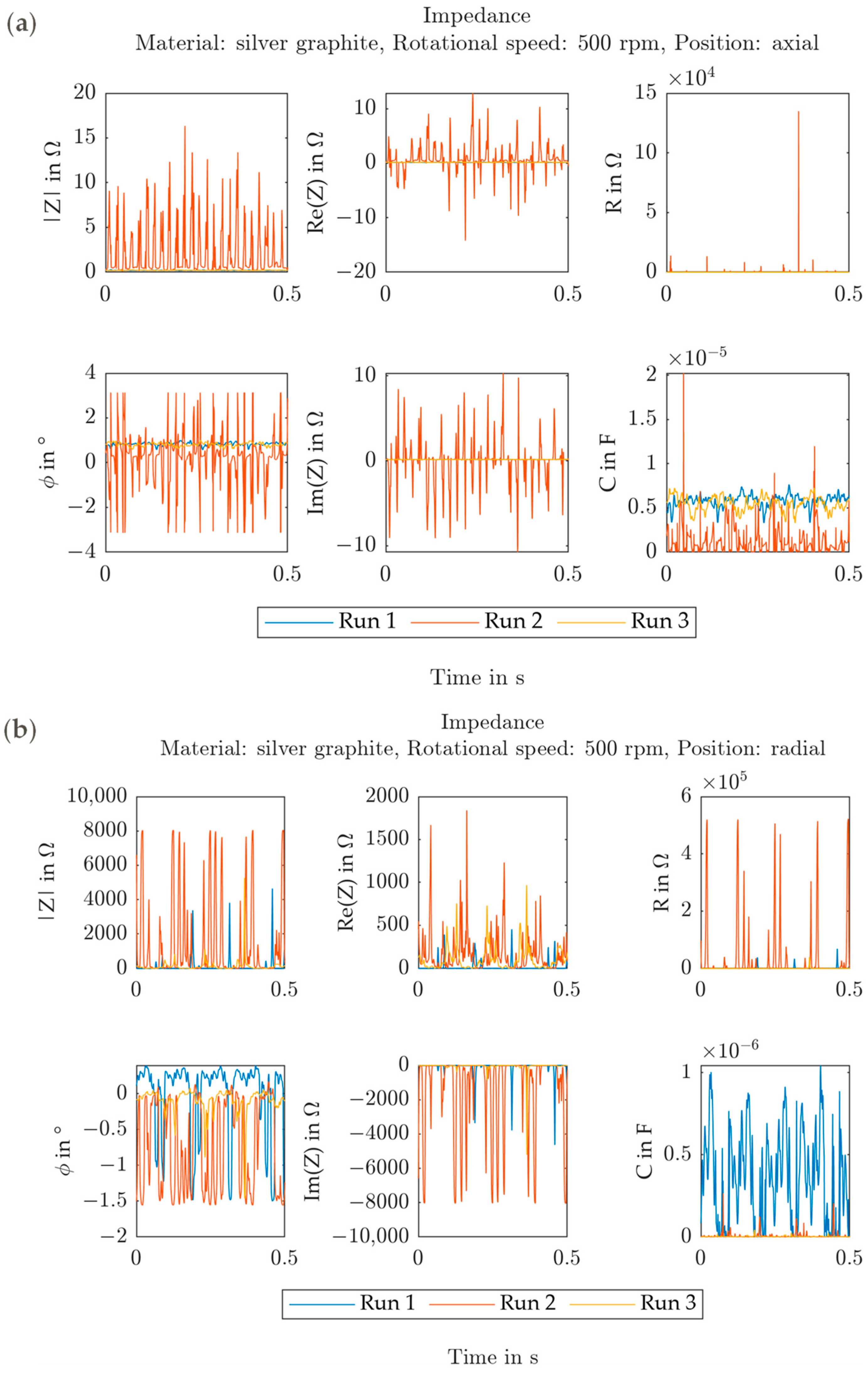
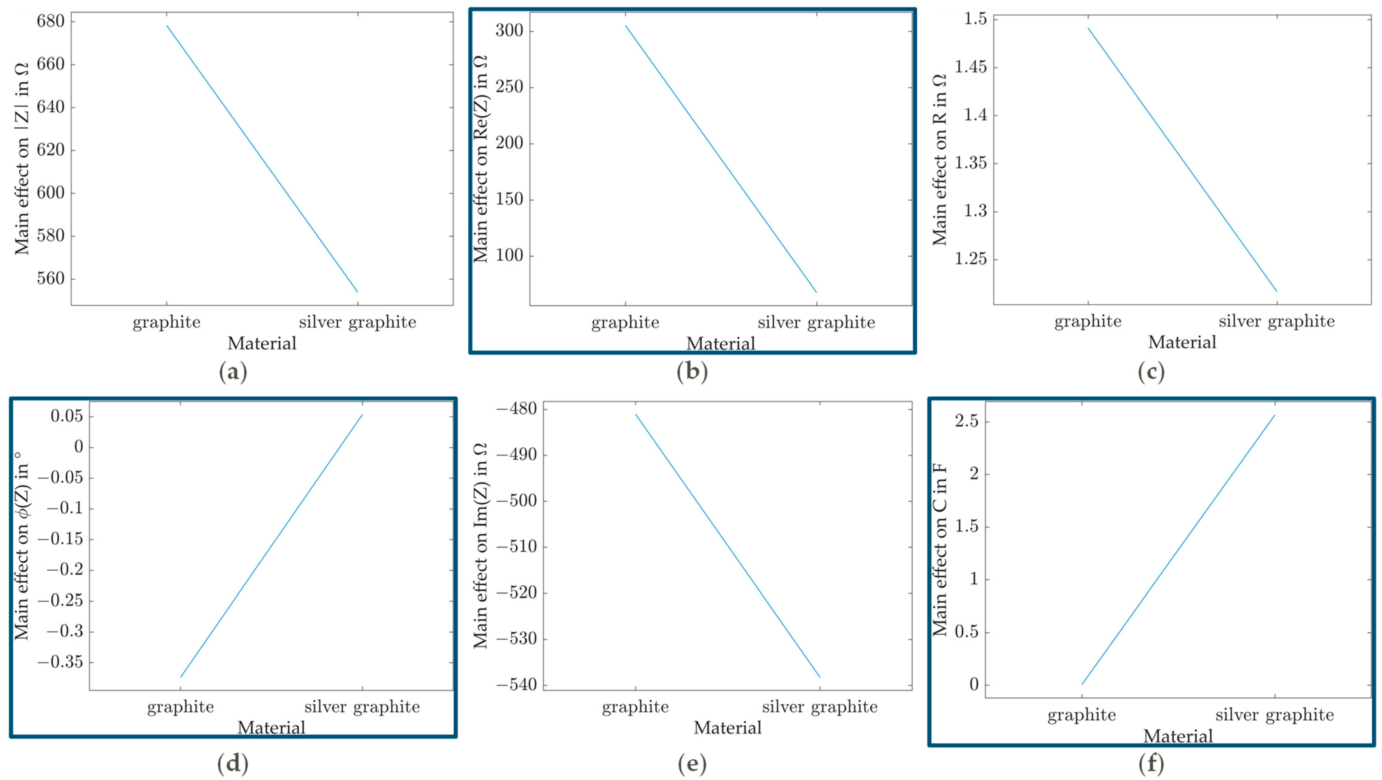
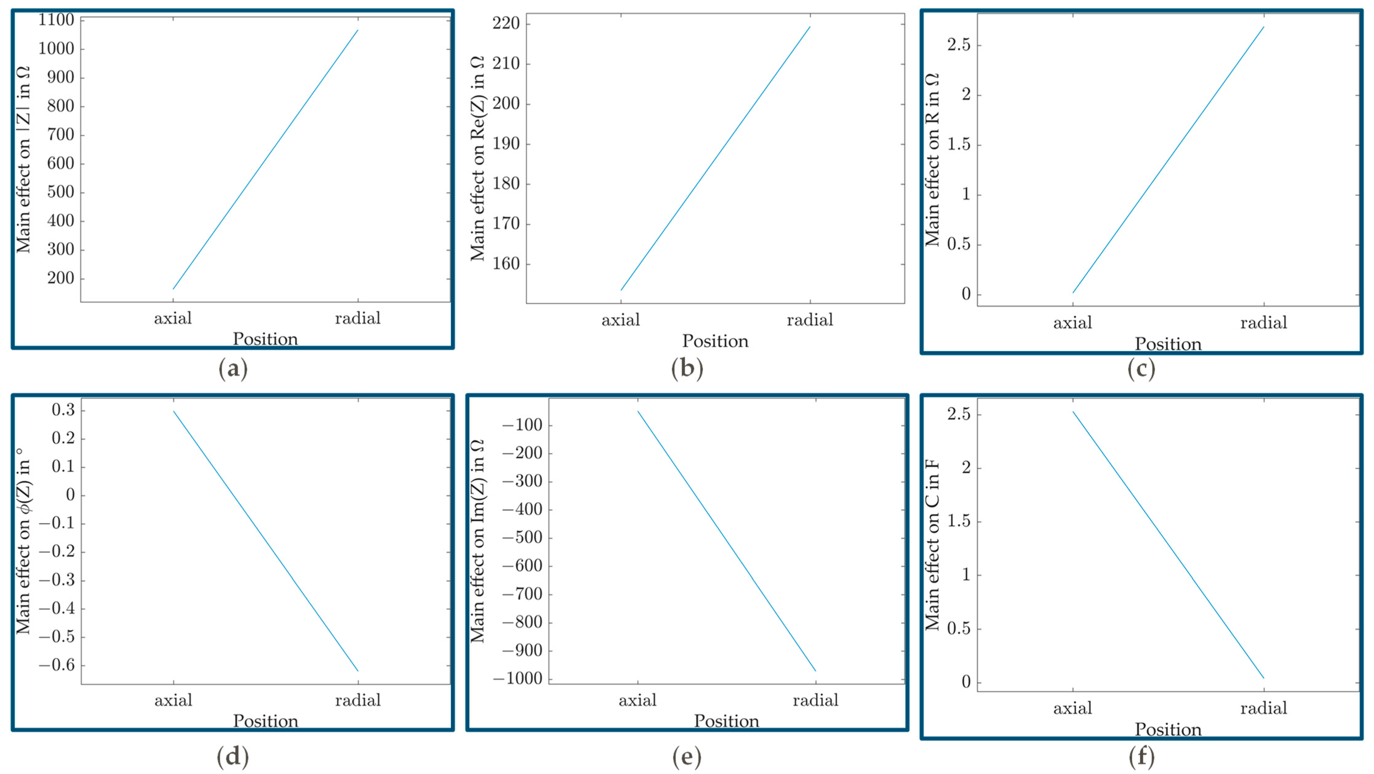
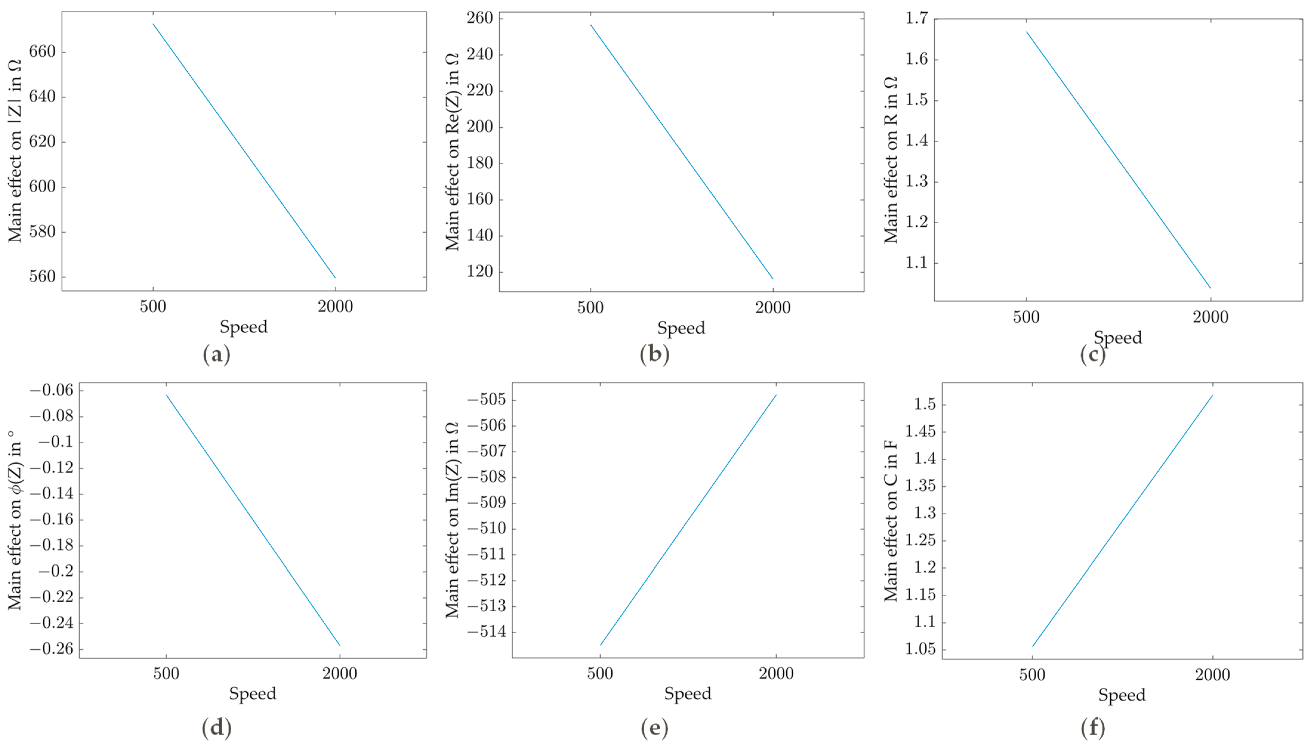
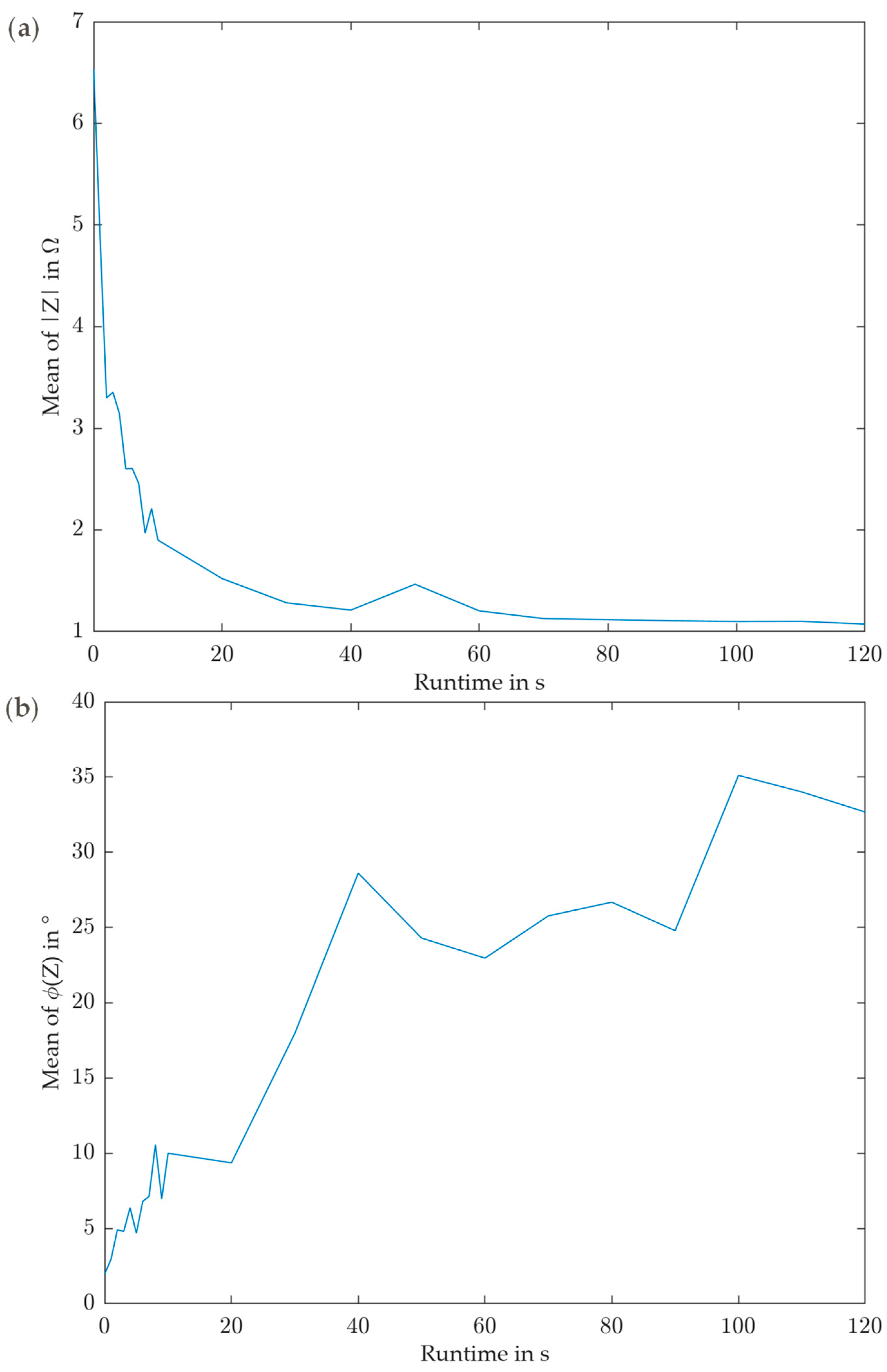
From the experimental series carried out, it can be deduced for the impedance behavior of sliding contacts on the basis of a screening design that the material and position of the carbon brush have a significant influence on the impedance. Thus, the impedance of a silver graphite carbon brush is lower in absolute value and more resistive than a graphite carbon brush. Axial contacting also has a lower, more resistive, and more uniform impedance than radial contacting. In contrast, the rotational speed of the shaft has no significant effect on the impedance. The nature of the effect—e.g., whether it is linear or not—has not been investigated in this screening experiment, and has therefore not been conclusively clarified. For this, a larger number of operating conditions need to be investigated. The carrier frequency used plays a significant role and should always be considered. Furthermore, carbon brushes exhibit measurably verifiable run-in behavior, with the absolute value of the impedance decreasing with runtime, while the phase angle increases with runtime.
For the application as a signal transmission element for the sensory utilization of machine elements, such as rolling element bearings, contacting types with the lowest possible and at the same time uniform impedance are suitable, whereby resistive components are often preferred to capacitive components. This is due to the fact that in the sensory utilization of rolling element bearings, the capacitance represents the quantity of interest; thus, the measurement of the capacitance should be as undistorted as possible. For this reason, carbon brushes made of silver graphite rather than graphite are more suitable for this application. In addition, sliding contacts should—as far as technically possible—be mounted in an axial position; the contact speed plays only a subordinate role. Furthermore, the carrier frequency for the impedance measurement should be carefully selected, and its influence on the impedance behavior of the sliding contact and the rest of the cabling should be considered. Due to the pronounced run-in behavior, relevant impedance measurements should only be performed after the run-in time in order to reduce uncertainty.
Further steps can be derived from this work for further research. Further materials for sliding contacts can be investigated, since only exemplary carbon brushes from an exemplary manufacturer were examined in this research. However, a classification of different materials is not the focus of this work and would go beyond its scope. In addition to the materials for carbon brushes, the materials of the slip ring can also be investigated. In the context of this work, conventional lathed steel was used for the shaft in order to get as close as possible to the materials and machining quality of conventional shafts, and thus reduce the potential integration and transfer effort in a real technical system. However, many parameters exist, such as surface finishes, whose variation would be of interest. Another interesting factor, which was not systematically investigated in this work, is the influence of temperature. In the context of the experiments performed in this work, the surrounding temperature was kept at a constant level. But this can be varied, as can the shaft temperature and thus the contact temperature, and its influence can be analyzed. Two further aspects of investigation relevant to the application are durability tests of carbon brushes and how the impedance behaves over the lifespan, as well as the investigation of the influence of contaminations such as lubricants or other operating fluids. In order to make it as simple as possible to integrate SuME in situ in the process, a solution must also be developed to place sliding contacts as close as possible to the machine element. This includes, placement in the direct proximity of lubricants, and other operating fluids within the technical system, such as a gearbox housing.


