Article

Blast Effects on Hyperloop’s Cylindrical Thin-Shell Structures

by
Sakdirat Kaewunruen
1,*,
Joseph Roxburgh
2 and
Alex M. Remennikov
3
1
Department of Civil Engineering, School of Engineering, University of Birmingham, Edgbaston, Birmingham B15 2TT, UK
2
Department of Mechanical Engineering, School of Engineering, University of Birmingham, Edgbaston, Birmingham B15 2TT, UK
3
School of Civil, Mining, and Environmental Engineering, University of Wollongong, Wollongong, NSW 2522, Australia
*
Author to whom correspondence should be addressed.
Machines 2023, 11(10), 938; https://doi.org/10.3390/machines11100938
Submission received: 8 August 2023 / Revised: 27 September 2023 / Accepted: 29 September 2023 / Published: 1 October 2023
(This article belongs to the Special Issue Development of Condition Monitoring Systems in Railway)

Abstract

:
Super-high-speed guided systems such as hyperloops and MagLev are highly at risk of cyber and physical threats from either natural or man-made hazards. This study thus adopts a nonlinear finite element method to investigate and analyse blast responses of a spatial thin-shell structure formed as an essential part of the Hyperloop tunnelling system. The thin-shell structure is a longitudinal cylindrical tube used in hyperloop rail concepts that will have the capability to carry passenger pods travelling at speeds in excess of 1000 km/h. A robust parametric study has been carried out on a thin-shell metallic cylinder in accordance with experimental results to validate the blast simulation modelling approach. In addition, case studies have been conducted to simulate the effects of varied charge loading (TNT equivalent) of 10 kg, 15 kg and 20 kg. Since the hyperloop system is in its development stages, potential design modifications to adjust the thickness of the thin-shell cylinder are also simulated. Our findings demonstrate that thicker walls of 30 mm yield almost negligible dynamic displacements with lower blast pressures. However, this modification can cause serious ramifications in terms of infrastructure costs. On this ground, venting ports for blast mitigation have been proposed to alter and alleviate blast effects on the tube deformations. The novel insights reveal that increased venting port sizes can significantly increase the impulse deformations of the hyperloop tube but are key in reducing blast pressures within the asset infrastructure. These findings will inform hyperloop engineers about potential design solutions to ensure safety and reliability of future hyperloop rail travels amid the risks and uncertainties of cyber and physical threats.

1. Introduction

Transport infrastructures are the critical infrastructures that are vital for modern society, green economy and high quality of life. Any disruption to a critical infrastructure can cause widespread effects on individuals, communities, economy, and the environment [1,2,3]. In general, physical infrastructures can be at risk of natural and man-made hazards. Motivations for man-made attacks include financial gain, espionage and terrorism. The UK National Infrastructure Commission has highlighted that investment in infrastructure resilience often occurs after a disruption or a failure. The commission has suggested that infrastructure operators establish strategies, methods and tools for long-term infrastructure resilience, which could require new investments for design modification, retrofit, renovation or renewal [4]. The projections and modelling of natural and man-made hazards are often uncertain, implying that the exact nature and magnitude of the increased risk to critical infrastructures is unclear and unfathomable. For example, estimates for changes in windstorms, flash-flooding, lightning and terrorist attack events are particularly uncertain. The uncertainty and the unknown can make resilience planning and investment decisions highly challenging, chaotic and indeterministic. Therefore, it is very necessary to develop a variety of tools, methods, strategies and pragmatic tactics to support the development of short- and long-term resilience plans, including flexible decision-making frameworks and alternative design solutions that account for uncertainty, and adaptation options, which can provide value-added benefits under a wide range of extreme event scenarios [5,6]. These scenarios should span across various types and ranges of potential tactics that malicious actors may use or incite to carry out an attack on the infrastructure.
Researching the effects of blast loading on infrastructure is an evolving domain within civil and mechanical engineering asset management frameworks. Modern-day attacks from terrorism remain a current and ever-changing threat to society, in particularly to public transportation, where studies have shown that, between 1970 and 2010, there have been a total of 3955 attacks on public transport systems recorded in over 82 countries [7,8]. Without any data providing evidence of reduction in the threats from terrorism in the coming years, continued research into the effects of blast loading and blast mitigation methods on engineering structures and components of critical infrastructures (especially thin-shell structures for hyperloop systems) should be developed to prevent fatalities and create a safer environment for the public. However little research has gone into the domain of blast loading on thin-shell cylinders, although cylindrical structures are widely used in the transportation industry such as tunnelling systems, tube systems, pipelines, and hyperloop systems [9,10]. A clear knowledge gap has therefore been identified, and this study aims to consolidate further understanding on how cylindrical thin-shell structures, which form an essential part of modern super-high-speed guided transport (i.e., Hyperloop systems), react under blast loading conditions. Figure 1 illustrates the hyperloop tunnelling system where cylindrical shell theory applies. The widely used materials for curved structures or structural thin shells tend to be steel or other metallic materials. There has been a plan to adopt composites materials for the thin shells in the future. However, the scope of this study will be placed on the metallic materials.
The origins of thin-shell structures predate modern day architecture and design, where the development of shell analysis was first focused on by Bernoulli and Euler [11]. However, as early theories of thin-shell analysis were presented by 2D partial differential equations, they are commonly considered as an approximate technique. Accuracy was limited to the assumptions made in the analysis and boundary conditions. Improving the approximations for thin-shell analysis has been a constant development process, where in the 1950s scientists such as Clough developed Finite Element Analysis [12]. Advancements in the understanding of thin-shell structures have allowed engineers and designers to utilise these theories to develop vehicles in industries such as aerospace. NASA’s Saturn V rocket, as well as the Airbus A380 and Boeing 787 Dreamliner are all examples of how thin-shell mechanics can be used in the domain of vehicle design [11]. Shell structures can be considered to be thin when the following criteria are met [13]:
max h R < 1 20 h = C y l i n d r i c a l   T h i c k n e s s R = R a d i u s   o f   C u r v a t u r e
In general, thin-shell structures have a very high value of spatial stiffness and a large load-bearing capacity due to the curvature of the surface. This often stems from the combined arching and membrane stiffening effects. The thinness of shell structures further helps resist traverse loads through the internal membrane stresses [14]. However, it is to be noted that having an overly thin shell can cause critical structural instabilities when subject to external forces such as blast loading.
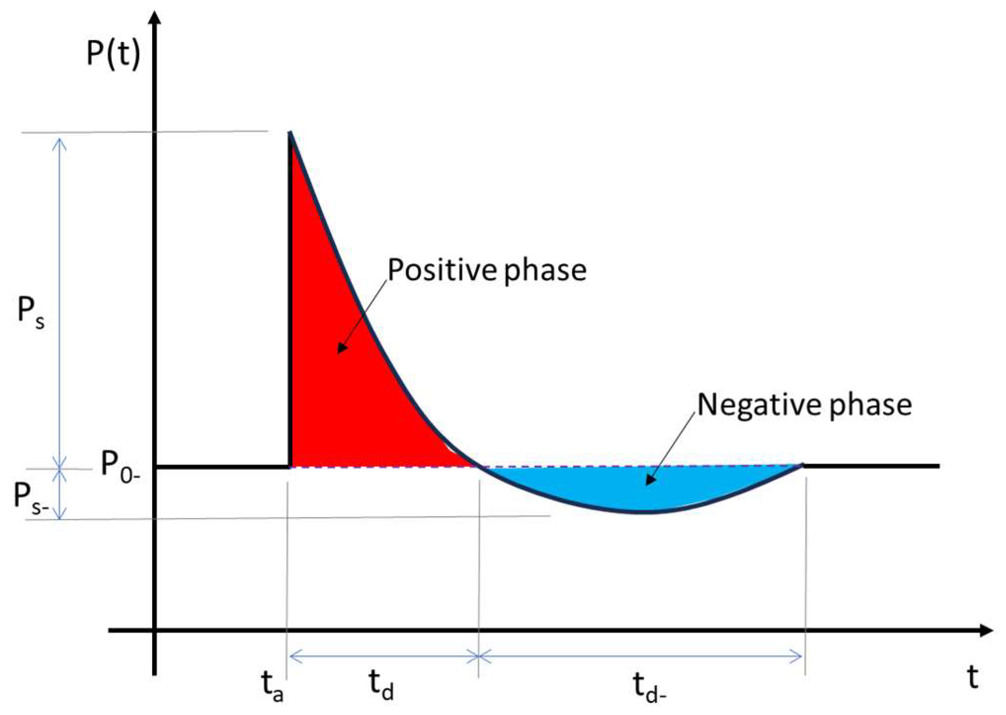
Simulations of blast waves, as illustrated in Figure 2, can be easily characterised using a pressure–time function, describing how the blast develops throughout each stage of detonation [5,15]. The size of the pressure recorded is defined depending on the stand-off distance to the blast and the size of the charge [16], with two main positive and negative phases. The arrival time ta of the blast is where ps (peak overpressure) occurs. The blast then falls back to po at time td, where the pressure then drops below the reference until it reaches maximum negative pressure pmin. The positive phase of the pulse duration can be expressed using the Friedlander Equation (2), showing the sudden step change in pressure, followed by an exponential decay in pressure [17].
P t = P s ( 1 t t a t d ) e t t a θ P t = p r e s s u r e θ = d e c a y   c o e f f i c i e n t
This study amins to investigate the dynamic response of metallic cylindrical thin-shell structures when exposed to external blast loading forces, in order to gain new insights into the resilience of the hyperloop transport systems. Note that metallic materials have been adopted widely for the design of modular tubes in practice. Whilst some areas of design encourage the buckling of thin-shell cylinders [18], increasing the ability of thin-shell cylinders to withstand buckling from blast loading in an operating environment is a crucial focus of this research. In this study, simulations of extreme event scenarios will be conducted using a nonlinear finite element method based on LS-DYNA. The key research objectives are (i) to gain a better understanding of blast loading effects on cylindrical thin-shell structures and the effects the charge has on rigid bodies; (ii) to establish an appropriate case study and simulate how blast loading can affect its structure; and (iii) to design and simulate blast mitigation techniques to reduce blast impulse, deformation and fatality rates for the selected case study. The insights derived from this study will help hyperloop engineers by offering new alternative solutions to enable the resilience-based design of the hyperloop systems.

2. Materials and Methods

2.1. Case Study

There are multiple types of the hyperloop system at different technological and operational readiness levels. Prior to developing computer simulations of blast effects on hyperloop thin-shell structures, a suitable case study is required to be selected. In reality, the hyperloop system concept is still in its infancy and, as of yet, no company has a fully operational system that is open to public use. This causes difficulties when selecting a case study, as there are limited information resources on hyperloop infrastructure which could define definitive specifications on crucial points of analysis. Currently, there is also a very limited amount of hyperloop research that stretches beyond a concept or into a developed physical prototype. Having said this, the development of hyperloops is continuing and global operations by many hyperloop companies will add to the body of research. Table 1 highlights operating companies undertaking hyperloop system designs, showing critical research.
Based on data integrity and systems readiness, the hyperloop system selected for the case study is Virgin Hyperloop One and its associated concept XP-1 pod. As illustrated in Figure 3, the structures of the hyperloop system to be analysed include the pod and the structural steel tube it operates in. The tube is a cylindrical structure made from 20 mm thin-sheet steel with an internal diameter of 3.3 m [19]. The tube is pressurised to a value of 100 Pa. The test track spans a distance of 500 m at a varying height off the ground, depending on surface undulation. Current operational tests have only reached 160 km/h on the track at this stage [23]. The XP-1 pod is a thin-shell tubular structure 8.7 m in length, 2.4 m width and a height of 2.7 m; however, length of pod will vary when commercially available to accommodate a higher number of passengers. In this study, the 10 kg explosive (TNT equivalent) will be placed at varied locations, both within and on the outside of the structure to analyse where weaknesses are most prominent.

2.2. Blast Simulations

The hyperloop structure is to be subject to a uniformly distributed blast load, simulated within LS-Prepost package [24]. The empirical LOAD_BLAST_ENHANCED pre-post function will be used to model the far-field charge. TNT blast loading can be carried out in many forms, such as surface blasts, hemispherical blasts or spherical free air blasts, each with their own unique pressure wave parameters. The tube and pod formulating the hyperloop will be simulated using a spherical TNT charge, where the scaling law is given by Equation (3) [24]. The hyperloop itself will be modelled in Solidworks and then imported into LS-DYNA as a step file for FEA blast loading analysis.
Z = R W 3 R = D i s t a n c e   f r o m   D e t o n a t i o n   m W = T N T   C h a r g e   kg
Prior to modelling the hyperloop thin-shell structures, a parametric study was produced to validate experimental procedures used to ensure the accurate simulation of blast loading. The parameters used in the parametric study are aimed to validate how the thin-shell steel that the hyperloop structures are made from will react under blast loading. LS-DYNA offers a wide range of modelling techniques to allow the user to create a detailed simulation for their specific scenario. An experiment conducted by Rushton et al. [25] uses FEA analysis to investigate a cylinder’s dynamic response to blast loading. The experiment will be validated with LS-DYNA modelling to demonstrate the most accurate simulation parameters to be carried forward into the hyperloop case study.

2.3. Blast Experimental Validation

Rushton et al. [25] have conducted numerical and experimental analysis on a steel pipe to evaluate the effectiveness of its resistance to blast-induced deformation, as well as looking at the failure mechanisms under high loading. The pipe, which was used for gaining experimental values of deformation, had a thickness of 9.5 mm with an outer diameter of 324 mm and length 800 mm. The material was API05LX-42 mild steel with a minimum yield stress of 289.6 MPa and minimum tensile stress of 413.7 MPa. Tests were conducted with a 0.8 kg TNT-equivalent spherical explosive charge (Z = 0.16 m/kg1/3) placed at the centre of the pipe, where numerical analysis was conducted on ANSYS AUTODYN. Due to the simplicity of the simulation, no quarter modelling was required, as computational time and cost were fairly low. The AUTODYN simulation was able to indicate maximum deflection, pressure and hoop strain (equation) at various points along the steel tube. Although Rushton et al. [25] used AUTODYN for the simulation, the parametric study is to be conducted on LS-DYNA, which will be able to accurately recreate the same parameters and validate results. The shell model is to be developed in LS-DYNA Prepost utilising the LOAD_BLAST_ENHANCED keyword to simulate the experiment carried out by Rushton et al. [25]. Once complete, the simulation can provide crucial validation measures such as mesh convergence accuracy, blast pressure validation and material studies, and an element formulation can be completed to ensure the hyperloop case study is accurately validated.

2.4. Materials Modeling and Selection

Suitable material modelling is required to obtain reasonably accurate simulations to demonstrate how the thin-shell structures will react under blast loading. Previous studies have identified a variety of appropriate material-modelling approaches for metallic thin-shell cylinders. They exhibit acceptable correlations between numerical and experimental results. Element formulation within LS-DYNA should be carefully selected in order to adequately represent all critical parameters. The following information highlights potentially suitable LS-DYNA material IDs and where they are best suited for simulation purposes. A parametric study for the hyperloop materials for the tube can be conducted, with information found below:
  • MAT_001: Used for elements such as beams, shells and other solids, MAT_001 is used to model isentropic elastic properties of materials [26]. A specialisation of this material allows the modelling of fluids.
  • MAT_015: MAT_015 is used for when element strain rates have a large range of values and the temperature of the model is sufficient to cause material softening [26]. The Johnson/Cook strain and temperature sensitive plasticity is sometimes used for problems where the strain rates vary over a large range and adiabatic temperature increases due to plastic heating cause material softening. When used with solid elements, this model requires an equation-of-state. If thermal effects and damage are unimportant, the much less expensive *MAT_ SIMPLIFIED_JOHNSON_COOK model is recommended. The simplified model can be used with beam elements. Solid elements, when using MAT_015, are required to use an equation of state to help model the thermal and damage effects of the material. Li et al. [27] use MAT_015 to model the dynamic response of a metallic square plate with pre-formed circular holes as it accurately simulates maximum midpoint displacement and local deformation around the pre-formed holes. Mohotti et al. [28] make use of MAT_015 to account for strain hardening, strain rates and temperature effects to show the blast reduction effectiveness of polymer coatings on steel plates.
  • MAT_003: Nelson and O’Tool [29] used MAT_003 to simulate the kinematic hardening plasticity of all metallic elements in their composite cylinders. Experiments are approximated using a bi-linear stress strain curve to show how the metallic elements within the composite cylinder can predict the failure limit. Cost-effective modelling for materials is often used for beams and shells [26]. This model is suited for modelling isotropic and kinematic hardening plasticity with the option of including rate effects. It is a very cost-effective model and is available for beam (Hughes–Liu), shell, and solid elements.
  • MAT_024: A simple model that can be used for a diverse range of materials to simulate elasto-plastic elements with stress/strain features. It is an elasto-plastic material with an arbitrary stress as a function of strain curve that can also have strain rate dependency. Failure based on a plastic strain or a minimum time step size can be defined. Often used in blast loading as failure due to plastic strain can be set.

2.5. Mesh Convergence

An important validation technique prior to simulating final results is a mesh convergence study for the hyperloop model. LS-DYNA, along with other FE software programs, creates a series of nodes, which have a certain number of degrees of freedom (DOF). Each node calculates pre-set parameters at that point on the model. Adding nodes, however, increases the overall intricacy of the model, which further increases computational analysis time. A mesh convergence study is used to balance the optimum number of DOFs in order for the model response to be sufficiently accurate, but not take an excess amount of time to run. Convergence of a mesh could be considered satisfactory at the point when the results of analysis remain constant regardless of further mesh refinement.

2.6. Blast Mitigation Design Implementations

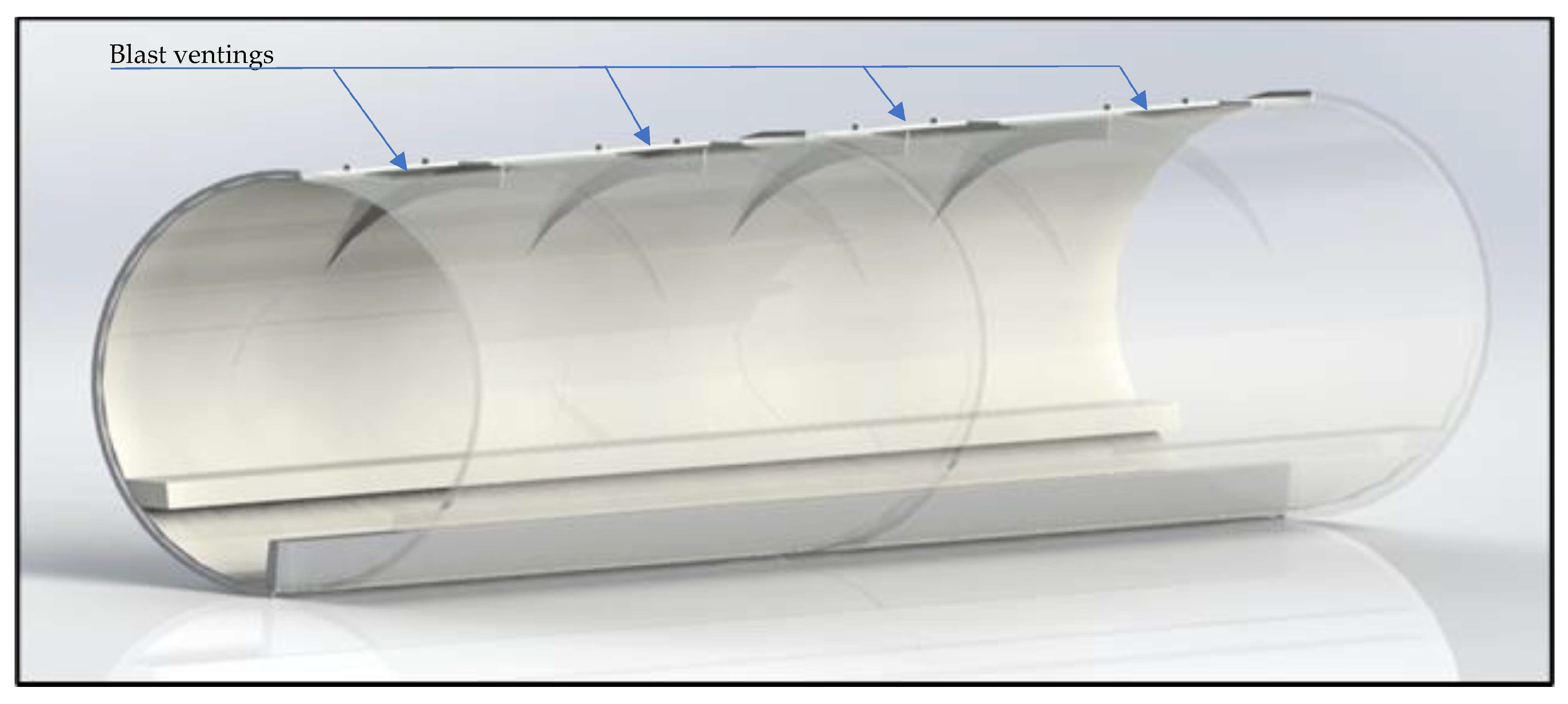
In practice, the requirement for explosion-resistant designs is increasingly becoming a prevalent design parameter. To improve resilience planning, alternative solutions for design adjustment and retrofit are critical. Thin-shell structures, such as cylinders, typically have a high structural instability and are sensitive to vibrations, which lead them to have a load capacity limited by dynamic elastic buckling [30]. Fatality rates if hyperloop infrastructure was to be targeted by terrorist attacks would prove catastrophic. The catastrophic damage would also cause significant financial penalty and environmental impacts. With tubes working at an operating pressure of 100 Pa, any loss in pressurisation within the pods, as well as blast loading on the occupants, would be fatal [31]. One such method for reducing pressure fronts from an explosive source is the use of blast intersections within the hyperloop tube. Blast intersections, as illustrated in Figure 4, are methods of breaking the propagating wave front into smaller wave fronts, which can reduce the overall peak pressure. This would help reduce the channelling effect caused by explosive loads in confined spaces, something the hyperloop tube would suffer from. However, if intersections are implemented onto the hyperloop tubes, the reduction in cross sectional area could lead to potential internal transonic flow choking [32], reducing hyperloop’s operational speed. Choking limitations would concern the hyperloop when travelling at transonic speeds, where the flow around the capsule reaches Mach 1 and the capsule is choked. Any further increase in speed creates a large pressure build up at the front of the pod, preventing any further mass flow in a condition known as the Krantrowitz limit [33]. Numerical analyses by Oh et al. [34] revealed that blockage ratio values (Apod/Atube) of 0.25 and 0.36 create a critical Mach number of 0.50 and 0.41, respectively. Overcoming the Krantrowitz limit can be carried out by either increasing the tube diameter for a smaller blockage ratio or equipping the pod with an axial compressor for more air to pass around the capsule [35].
Studies conducted by Langdon et al. [36] and Larcher et al. [15] showed that using venting ports as a pressure release mechanism has proven to be an effective method in reducing blast impulse. Results from Larcher et al. [15] showed that a 2 m vent length within a train carriage is an effective size for venting to make a substantial difference on pressure impulse. It is clear that the vents can suppress the blast effect. In this study, the vents will be applied to the tube systems where the blast pressure can be released, in order to assess its attenuation characteristics. As a result, further simulations are carried out on hyperloop specific pressure release vents of varying dimensions to evaluate what causes minimum responses to the tube. Incorporated into the design are two RS PRO Electric Linear Actuators [37], which are used to lift the vent ports with an operating stroke of 300 mm and a combined maximum load capacity of 8000 N (pull). The venting ports will be activated if the pressure in the tube reaches a blast condition of 10 MPa, shown by internal pressure gauges.

3. Results

The model validation was first investigated. Mesh convergence analysis was presented to obtain optimal mesh size for the simulations. Then, the parametric study was conducted to yield new findings of the blast effects on the hyperloop’s thin-shell structure systems.

3.1. Mesh Convergence Assessment

Figure 5 shows the mesh convergence study conducted based upon the parametric study, simulating the Rushton et al. (2008) experiment. It can be seen from Table 2 that reducing the element size to produce a finer mesh enables the Von Misses Stress to converge to a stable result but significantly increases computation time. The optimal mesh size of 20 mm has been adopted.

3.2. Parametric Study

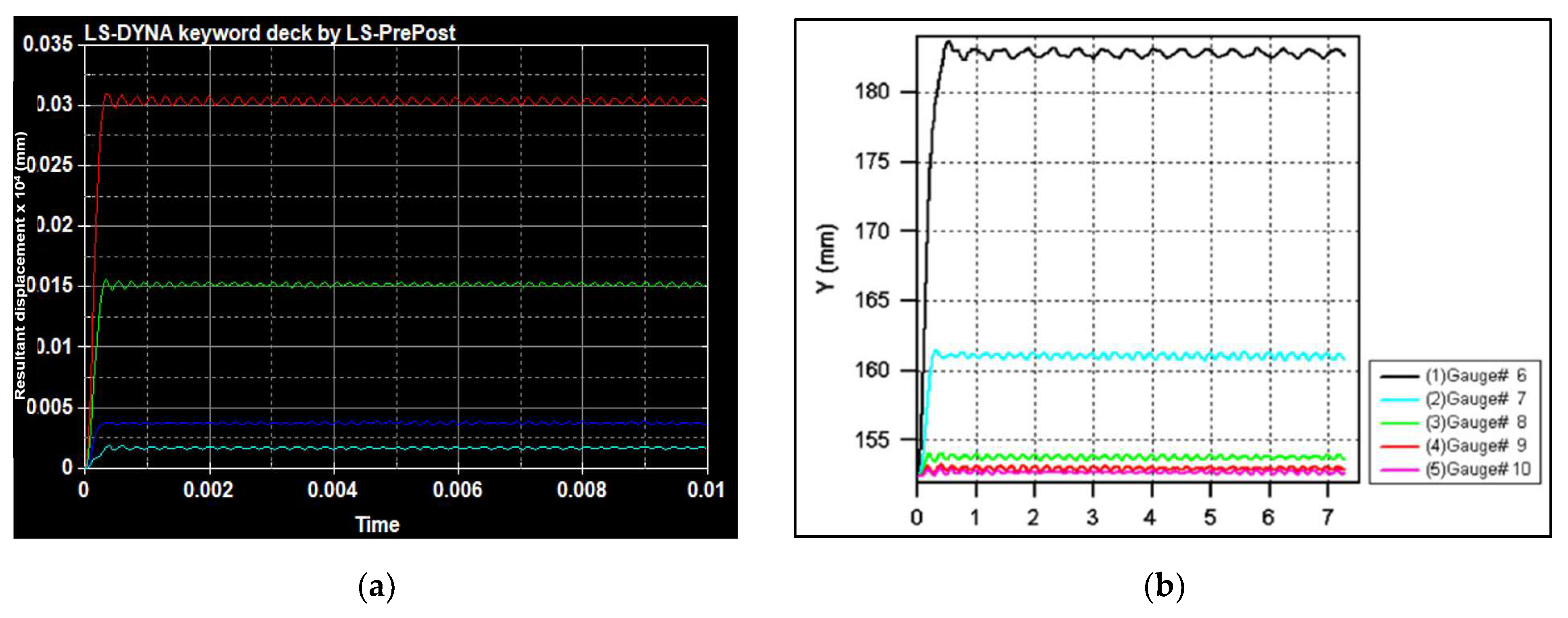
Figure 6a shows the resultant displacement of previous experiment [25] when the cylinder was exposed to a blast force of 0.8 kg TNT (Z = 0.16 m/kg1/3) and (b) is the parametric study aimed to validate procedures of that study to carry forward accurate simulation measures for the case study. The results from a previous study [25] indicated that the material models chosen can well predict the dynamic responses in a good agreement. The parametric results also revealed that the localised material points closer to a blast load (near field) will be much more affected by the impulse, compared to the points further away from the blast load (far field). The oscillation is reportedly due to the wave-induced dynamics of the structure.
Based on the materials’ properties in Table 3, the comparisons of numerical and experimental results show that the simulations are in good agreement with experimental results.
Table 4 indicates a close replication of the Rushton et al. [25] experiment, where the LS-DYNA simulation showed similar deflection values as to that of the parametric study. However, there are still inaccuracies within the study, highlighted at displacement gauge 2, where there is a 30.5% difference in deflection values. This could be due to the blast wave turbulence in the experiments. Looking at the materials used in the experiment, it was found that MAT_024 simulated the closest deflection values to API05LX-42 mild steel from the parametric study. Since the vent will be adopted in a similar range to Location No 1, MAT_024 had a maximum deflection percentage difference of 4.46% for Location No 1, whereas MAT_001 and MAT_003 had a 93.54% and 53.54% maximum deflection percentage difference, respectively, as shown in Table 5. As a result, MAT_024 will be carried over to simulate the steel tube in the case study.

3.3. Case Study

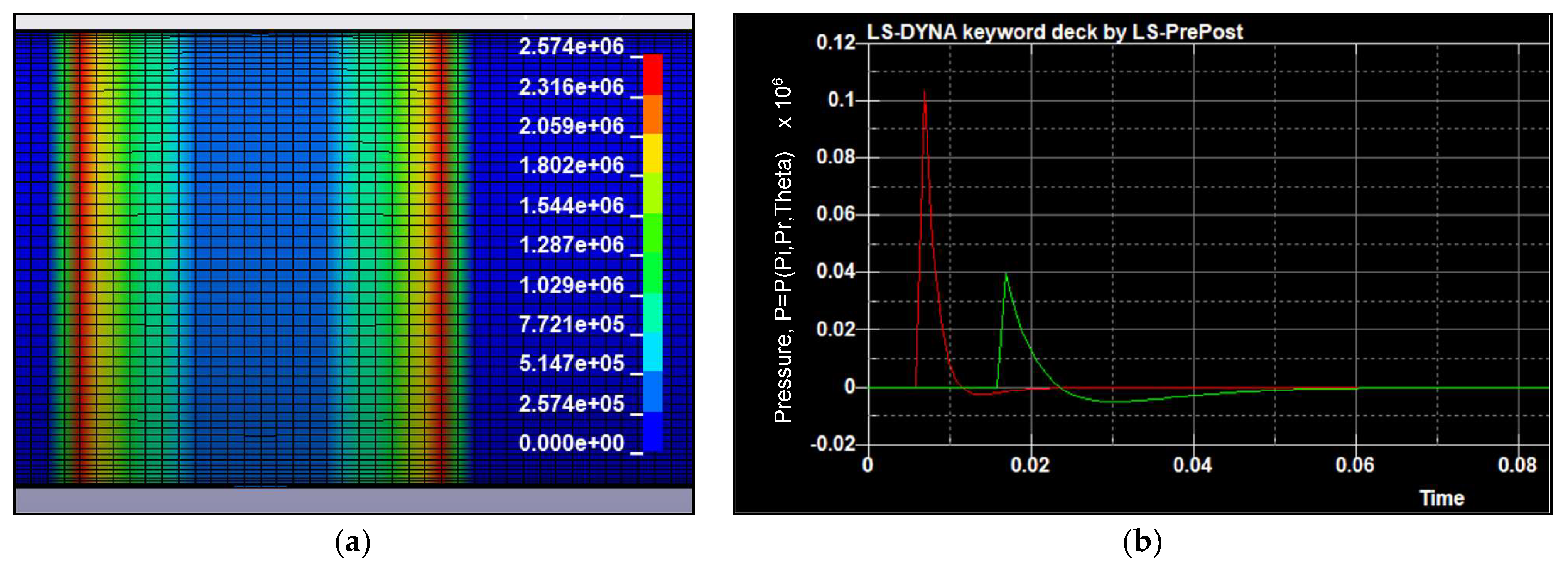
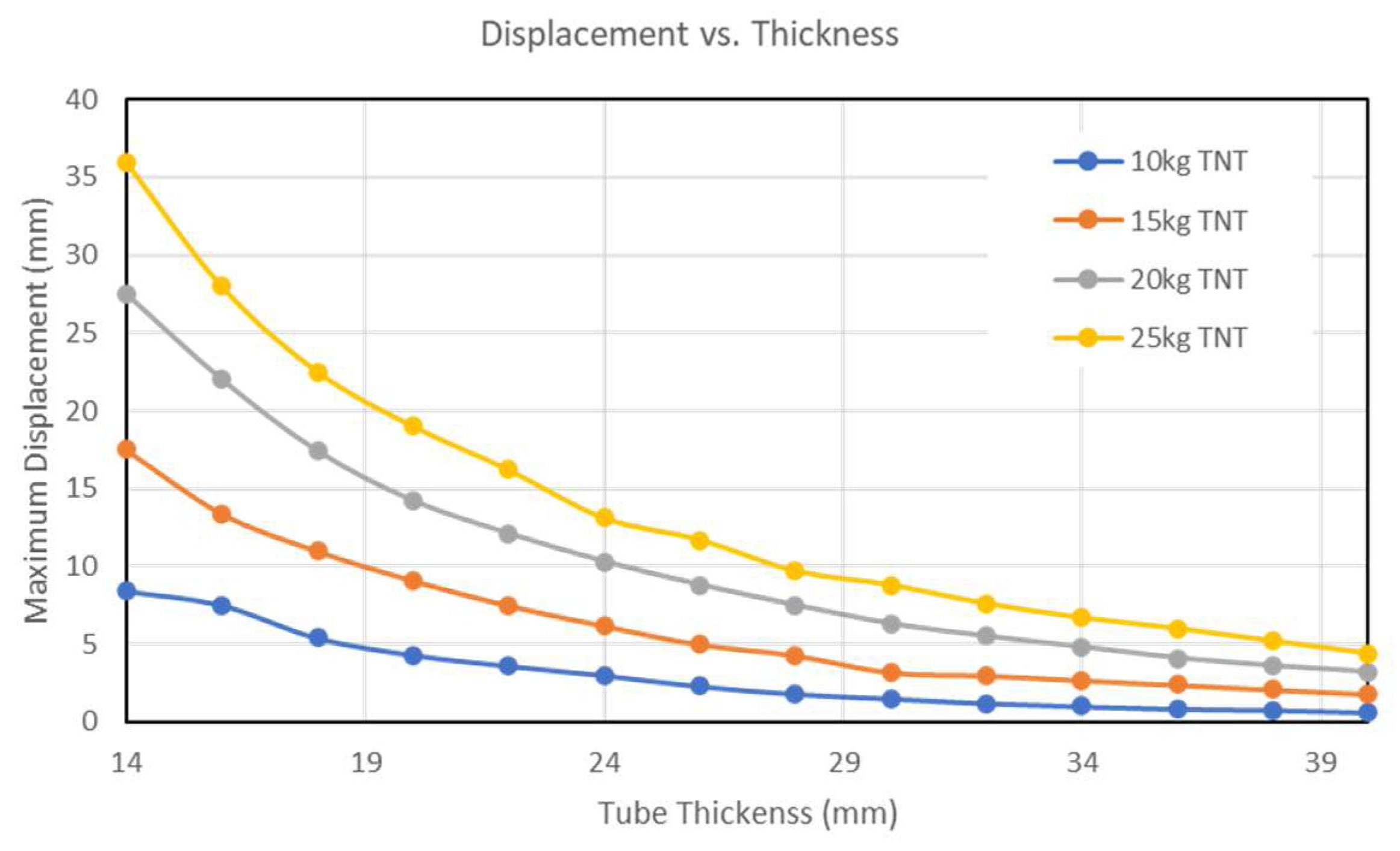
Using the simulation parameters validated in the parametric study, a fully scaled model of the hyperloop tube was created to show blast loading effects. Figure 7a depicts the pressure front from a 20 kg TNT spherical blast moving along the tube (at inner wall, Z = 0.42 m/kg1/3), where (b) shows pressure gauge readings placed 5 m and 10 m along the tube. Table 6 shows the deformation of the hyperloop tube, with a varied cylinder thickness and explosive load. The effects of tube wall thicknesses on the blast responses can be illustrated in Figure 8. Apparently, the thicker of the wall thickness, the lesser the dynamic displacement responses. Figure 9 shows displacement at the centre of the hyperloop tube. Note that the simulation conducted on LS-DYNA was taken at atmospheric pressure due to model limitations. The real hyperloop tubes are generally at a lower pressure during operations, but they can resume at atmospheric pressure during maintenance and during a hyperloop stop at stations. This study adopts the elastoplastic material properties of steel, and its damage is defined by only yielding characteristics. This study has not considered fracture mechanics. Due to the extensive time consumption, only optimal vent dimensions [15,36] are considered in the design modification for this study.

3.4. Blast Mitigation

Once the initial simulations are complete, venting strategies (as illustrated in Figure 4) were simulated as a blast mitigating technique on a hyperloop tube with a thickness of 20 mm. Based on results from Langdon et al. [36], which demonstrated that 2 m was an effective venting length to reduce blast impulse, our LS-DYNA models were modified by creating the blast intersections, as shown in Figure 10. Vent ports on the hyperloop tube are simulated from 500 mm to 2500 mm, all with a width of 800 mm. As venting is a proven method to reduce blast impulse, vents have been simulated to assess how maximum displacements are alleviated by these mitigation implementations. The new findings are portrayed in Figure 11, highlighting the influence of the vents’ length on the maximum displacements of the hyperloop tube. This relationship between the length of port vent and the blast wave suppression can help engineers to re-design or retrofit the hyperloop shell wall to effectively mitigate the blast effects.
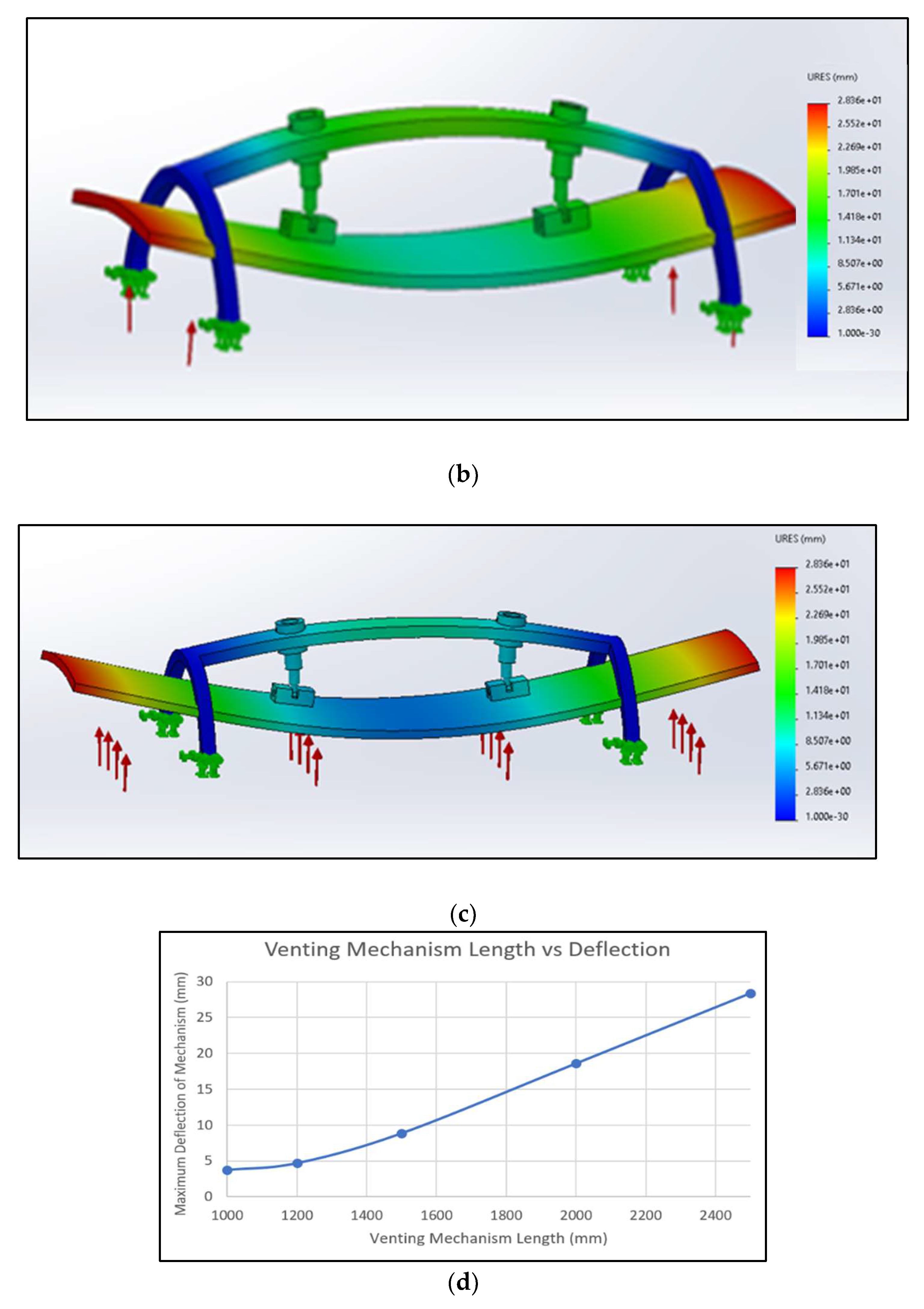
Vent mechanisms, as shown in Figure 4, were then separately simulated in Solidworks using blast pressure values calculated by the LS-DYNA case study, as illustrated in Figure 7. The purpose was to assess the structural integrity of the venting ports by assessing the dynamic deflection of the venting port mechanism and by assessing whether it can be reused in multiple blast loading events. This also helps to validate whether the proposed mitigation mechanism is a viable option for blast reduction, or further development is required to generate a robust design. Figure 12a shows vent port deflection using a pressure value of 0.1 × 10⁶ Pa. Each venting mechanism has a different length of vent plate to determine how vent dimensions can change the blast responses. A maximum deflection of 28.4 mm can be observed when using a vent plate of 2.5 m, where deflection significantly decreases to 4.7 mm if the vent plate is 1.2 m.

4. Discussions

The threats to critical infrastructures such as hyperloop systems exist in the transportation industry [38,39,40,41]. In many countries, such a risk is deemed to be very to extremely high [42,43,44]. Our study is thus critical to protect and to improve resilience of the transportation infrastructures.
Figure 5 demonstrates the convergence curve depicting the Von Misses stress vs. time to converge using the finite element simulations within the parametric study, and considers mesh convergence analysis. It reveals that a mesh size larger than 25 mm produces slightly unstable values for stresses, creating inaccurate blast loading results. This is relatively similar to other studies in the area [45,46,47]. However, a mesh element size smaller than 15 mm is an unnecessary value as stress has reached a stable value where convergence time significantly increases. Due to the large displacement values when simulating the mesh convergence, it also limits the accuracy of the model as the program does not timely update the blast pressure load directions as the tube deforms. This aspect can be resolved by a nonlinear iterative simulation, since it can timely update the program at each solution step depending on its deformation. Based on our parametric study, 20 mm element size has been selected as the optimum value for modelling in the study, and is brought forward for meshing the case study. However, it was found that simulations using 20 mm mesh size within LS-DYNA for our case studies prove to be computationally expensive. This is due to the scale of the hyperloop model when attempting to mesh the 20 m as opposed to the 0.8 m parametric study. Our study adopts full-scale, real-world dimensions of the hyperloop tunnelling system. As a result, the mesh element sizes have been increased to 30 mm for the tube model within LS-DYNA package, as this proves the optimum size between accurate readings and low convergence cost. This is reasonably a sufficient mesh density number to provide ample degrees of freedom for blast loading.
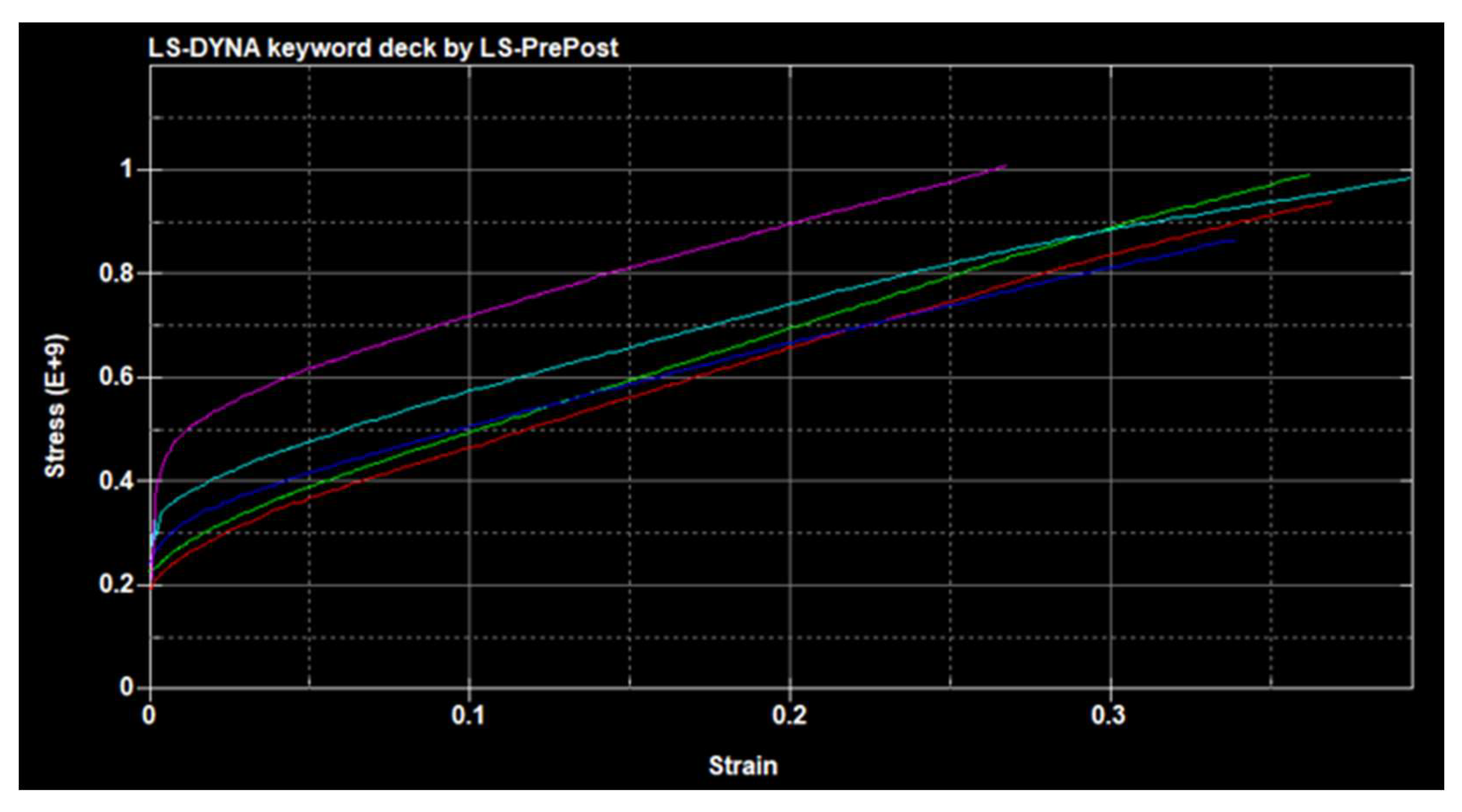
MAT_024 (Piecewise linear plasticity) from the materials model catalogue is chosen to model the steel material in the hyperloop case study. Based on our observations, MAT_024 offers an accurate maximum deformation, with only a 4% percentage difference between the parametric study and LS-DYNA simulations (as shown in Table 3 and Table 4). MAT_024 allows the strain rates of steel (see Appendix A, Figure A1) to be applied, meaning accurate deformation characteristics are simulated at high blast loading characteristics. The table ID of each strain rate allows for effective plastic strain vs. yield stress to be interpolated [48]. Although more in-depth failure criteria of composite structures can be modelled with MAT_MODEFIED_PIECEWISE_LINEAR_PLASTICITY, this is irrelevant for the case study, as only steel is simulated. However, this will be part of our future study where composites materials will be considered. Figure 6 highlights the slight discrepancies in deformation characteristics between experiments conducted by Rushton et al. [25] and the LS-DYNA simulations, where there is seen to be a maximum deformation difference of 4.6 mm. Reasons for this could stem from the fact that the Lagrangian LS-DYNA simulation has numerical issues due to element distortion limits which can occur when modelling large deformation [35]. Multi-material arbitrary Lagrange–Eulerian (ALE) is another simulation method that can be used to simulate dynamic deformations more accurately. Zaghoul et al. [49] uses this for blast effects on passenger trains, where structural parts are modelled using Lagrangian mesh and the air domain in which the blast waves travel is a Eulerian mesh. ALE Mapping for increased accuracy is used where pressure from a 1D air domain is mapped into the 3D domain. Despite yielding accurate results, these computational techniques are costly and have large computation times, which are not desired for the full-scale hyperloop case study [50].
Considering the blast mitigation implementation strategies, Figure 11 shows how hyperloop tube thickness and TNT loading alters the maximum deformation of the thin-shell structure. Results correlate to initial assumptions, where increasing TNT loading and reducing shell thickness increases deformation responses. The parametric simulation and case study use shell element formulation 16 (ELFORM_16) to achieve the accuracy of the numerical study. Detailed results can be found in Appendix A. ELFORM_16 is an ideal shell formulation for non-linear analysis, as sufficient warping stiffness means that simulations remain stable despite deformations [50]. Although it can be up to three times more computationally expensive than ELFORM_2 (Belytschko–Tsayshell), traverse shear correction means that no hourglassing effects can take place [51]. Spherical free air bust (BLAST_2) was used in the parametric and hyperloop case study to simulate blast loading TNT. BLAST_2 simulates the blast waves propagating spherically outwards with no prior contact on surfaces such as the ground before it interacts with the hyperloop structure [24]. With the charge suspended in air, this offers the most accurate recreation of an explosion from a terrorist threat. Parametric simulations are conducted by varying tube thicknesses. As the hyperloop systems are still in their concept design stages, a standardised thickness for tube infrastructure has yet to be set. Our new findings demonstrate that 30 mm tube thickness would be the desired dimensions, as there is negligible deformation at low TNT loads. With an estimated economical infrastructure cost of USD 4,000,000 per km [52], any thicker would generate large ramifications for development pricing. Similarly, increasing the size of the venting mechanism will also substantially increase infrastructure cost.
Another important facet is the deformation of the hyperloop tube when full-scale venting areas are introduced to the hyperloop tube system. The virtual experiments are carried out with a tube thickness of 20 mm and 20 kg TNT load. Although the initial simulation would have some inaccuracy due to a sealed tube not being simulated with a lower internal pressure value, blast venting is assumed to depressurise the tube. This means it can be accurately modelled at atmospheric pressure. As displayed in Figure 11, a positive linear trend between venting length and tube deformation can be observed. This can be accounted for due to the increased hoop stress, σ H (as shown in Equation (4)) and longitudinal stress, σ L (as shown in Equation (5)) caused from removing sections of the cylindrical tube. Reducing thickness (t) of the cylinder wall increases both σ H and σ L which accounts for the increased deformation when the hyperloop tube is fitted with venting ports. From these findings, it could be concluded that venting may not be the most appropriate method of reducing blast loading implications, where extreme levels of deformation could cause dangerous amounts of fragmentation. This could be countered by adding isotropic shell configurations or stiffening hoop plates to increase the rigidity of the hyperloop tube [14]. Although, in reality, the venting areas could help prevent an increase in σ h and σ h due to the decrease in pressure acting on the cylinder surface, the current simulations are limited by how it can model pressure dissipation. The current model uses LOAD_BLAST_SEGMENT simulations, meaning blast pressure for a given segment is calculated regardless of other segments subject to that same blast pressure. Segments are unaware of venting holes for pressure, calculating results in spite of the pressure load acting on other segments. Whilst this characteristic is expected for empirical blast models and acceptable for calculating blast responses [45,46,47], further development using MM-ALE simulations will provide further insight into blast loading and pressure dissipation on hyperloop structures. This will form a part of our future research.
σ H = P r t
σ L = P r 2 t
P = P r e s s u r e r = C y l i n d r i c a l   R a d i u s   t = T h i c k n e s s   o f   S h e l l
When considering the blast responses of venting mechanism (see details in Appendix A, Table A2), picking the optimum dimensions would have to be a balance between cost of manufacture, deformation caused, and venting area exposed. The venting mechanism that is 1000 mm in length (as illustrated in Figure 12)) only yields 4 mm of maximum blast deformation, with the actuators and venting plate withstanding blast force and not becoming compromised. Although this ensures the reusability and modularity of the venting mechanism, dimensions are below the optimum 2 m venting length found by Larcher et al. [15]. Our results thus provide a new alternative venting mechanism suitable for the hyperloop tube system.
Future considerations of this study are to not just blast deformations within the hyperloop model, but also pressure drop values from the various venting strategies. Although deformation characteristics have proven to be an insightful study into how hyperloop thin-shell structures react under blast loading, further pressure analyses can enable fatality models to be built. To determine pressure values that coincide with the effects of venting, a multi-material ALE simulation method can be adopted in future study. This would ensure air confined within the tube, as well as air surrounding the tube, would be modelled to enable pressure variations to be analysed. Multi-material ALE can simulate wave reflection and resultant superposition within the tube, a phenomenon that has been highlighted by Zaghloul et al. [49] as a critical factor of deformation in confined spaces. Other blast loading mitigation design improvements can be simulated in future studies to compare what methods are the most effective at reducing the failure of hyperloop infrastructure. Examples could include redesigning the hyperloop tube by adding composite isotropic shell configurations into the internal thin shell to improve its capacity to withstand pressure loading [14,53,54,55,56,57,58,59,60]. As previously mentioned, modelling different blasts using the LOAD_BLAST_ENHANCED keyword, such as hemispherical or surface blasts, could be investigated to see how deformation varies. This could be conducted both on the inside and outside of the tube to model various blast loading scenarios.
5. Conclusions

The paper aimed to investigate the blast effects on spatial thin-shell structures for critical transport infrastructures in which a knowledge gap is well present. Hyperloop tube systems are among the rapidly growing transport infrastructures to support super-high-speed travels. This domain of application is emerging and there is a need to investigate various risk and uncertainty aspects of the systems to ascertain public safety. The hyperloop tube system has thus been chosen as an appropriate thin shell case study for blast analyses. A robust parametric study was thus developed, in which suitable simulation parameters could be translated directly into the future hyperloop simulations. Validation of the models was conducted using previous experimental results. Modelling the experiments using LS-DYNA ensures that material non-linearities, as well as computational measures, are appropriate for the hyperloop simulations. Our results highlight the importance of tube thickness when considering blast loading effects on thin-shell structures. It was found that the 40 mm thickness of the tube wall causes minimal deflection under low TNT blasts. When creating venting areas to reduce blast pressure impulse, our new findings reveal that this tactic can impose a dramatic effect on the maximum blast deformation. This mitigation technique can significantly reduce the blast effects on the hyperloop tube by effectively alleviating the blast impulse and re-channelling the blast wave. Our future study will consider more alternative blast mitigation techniques and composite materials to enrich the resilience planning of the super-high-speed travel system.

Author Contributions

Conceptualisation, S.K. and J.R.; methodology, S.K., J.R. and A.M.R.; software, S.K. and A.M.R.; validation, S.K. and J.R.; formal analysis, S.K. and J.R.; investigation, S.K., J.R. and A.M.R.; resources, S.K.; data curation, J.R.; writing—original draft preparation, S.K. and J.R.; writing—review and editing, S.K. and J.R.; visualisation, J.R.; supervision, S.K.; project administration, S.K.; funding acquisition, S.K. All authors have read and agreed to the published version of the manuscript.

Funding

This research was funded by H2020 Marie Curie Action, grant number 691135 and Shift2Rail Project No. 730849.

Data Availability Statement

Data can be made available upon a reasonable request.

Acknowledgments

The authors wish to gratefully acknowledge the Japan Society for Promotion of Science (JSPS) for JSPS Invitation Research Fellowship (long-term), Grant No. L15701, at the Track Dynamics Laboratory, Railway Technical Research Institute and at Concrete Laboratory, the University of Tokyo, Tokyo, Japan. The JSPS financially supported this work as part of the research project entitled “Smart and reliable railway infra-structure”. Special thanks are given to the European Commission for H2020-MSCA-RISE Project No. 691135 “RISEN: Rail Infrastructure Systems Engineering Network”. Partial support from H2020 Shift2Rail Project No. 730849 (S-Code) is acknowledged. In addition, the sponsorships and assistance from LORAM, Transport for London (TfL), and RSSB (Rail Safety and Standard Board, UK) are highly appreciated.

Conflicts of Interest

The authors declare no conflict of interest.

Notations

P t Pressure Time Function
P m a x Maximum Peak Pressure (or Ps)
P 0 Atmospheric Reference Pressure
t d Blast Pressure Positive Phase Duration
Z Scaled Distance
R Distance
W TNT Charge Weight
A L E Arbitrary Lagrange–Eulerian

Appendix A

The following supporting information tabulates the visualisation in Figure 11 and Figure 12, respectively.
Table A1. Results of vent port length and how it alters maximum tube displacement.
Venting Port Length
(mm)
Maximum Dynamic Displacement of Hyperloop Tube (mm)
10 kg TNT15 kg TNT20 kg TNT25 kg TNT
50017304558
100030486892
15003880115140
200050100149180
250068120148215
Table A2. Vent mechanism displacement with varying lengths simulated with a 20 kg TNT load.
Venting MechanismLenth
(mm)
Maximum Mechanism Displacement
(mm)
110003.75
212004.70
315008.86
4200018.6
5250028.4
Figure A1. LS-DYNA Material graph showing stress/strain characteristics of steel at varied loading levels (Stress in Paskal): red: low strain rate; green and blue: moderate strain rate; and purple: high strain rate.
Machines 11 00938 g0a1

References

  1. UK Government Cabinet Office. Policy Paper: The UK Government Resilience Framework. 2022. Available online: https://www.gov.uk/government/publications/the-uk-government-resilience-framework/the-uk-government-resilience-framework-html (accessed on 1 September 2023).
  2. Kaewunruen, S.; Guo, Y.; Jing, G.; Matsumoto, A. Circular economy implementation in railway systems beyond net zero. Front. Built Environ. 2023, 9, 1239740. [Google Scholar] [CrossRef]
  3. Kaewunruen, S.; Osman, M. Dealing with disruptions in railway track inspection using risk-based machine learning. Sci. Rep. 2023, 13, 2141. [Google Scholar] [CrossRef]
  4. UK Government. Horizon Scanning: Physical Threats to Infrastructure, London, UK. 2023. Available online: https://post.parliament.uk/physical-threats-to-infrastructure/ (accessed on 1 August 2023).
  5. Remennikov, A.M. A review of methods for predicting bomb blast effects on buildings. J. Battlef. Technol. 2003, 6, 5–10. [Google Scholar]
  6. Osseiran, N.; Coles, I. Beirut Explosion: What Happened in Lebanon and Everything Else We Know. 2020. Available online: https://www.wsj.com/articles/beirut-explosion-what-happened-in-lebanon-and-everything-else-you-need-to-know-11596590426 (accessed on 26 September 2023).
  7. Strandberg, V. Rail Bound Traffic—A Prime Target for Contemporary Terrorist Attack? J. Transp. Secur. 2013, 6, 271–286. [Google Scholar] [CrossRef]
  8. O’Neil, C.; Robinson, A.M.; Ingleton, S. Mitigating the Effects of Firebomb and Blast Attacks on Metro Systems. Procedia Soc. Behav. Sci. 2012, 48, 3518–3527. [Google Scholar] [CrossRef]
  9. Wanchoo, P.; Matos, H.; Rousseau, C.-E.; Shukla, A. Investigations on air and underwater blast mitigation in polymeric composite structures—A review. Compos. Struct. 2021, 263, 113530. [Google Scholar] [CrossRef]
  10. Rennie, J.; Kaewunruen, S.; Baniotopoulos, C. Nonlinear Blast Responses of Thin Shell Roof Over Long Span Structures. Int. J. Struct. Stab. Dyn. 2021, 21, 2150031. [Google Scholar] [CrossRef]
  11. Altenbach, H.; Eremeyev, V. Thin-Walled Structural Elements: Classification, Classical and Advanced Theories, New Applications. In Shell-Like Structures: Advanced Theories and Applications; Springer: Cham, Germany, 2017. [Google Scholar]
  12. Clough, R.W.; Wilson, E.L. Dynamic finite element analysis of arbitrary thin shells. Comput. Struct. 1968, 1, 33–56. [Google Scholar] [CrossRef]
  13. Foroughi, H.; Moen, C.D.; Myers, A.; Tootkaboni, M.; Vieira, L.; Schafer, B.W. Analysis and Design of Thin Metallic Shell Structural Members—Current Practice and Future Research Needs. In Proceedings of the 2014 Annual Stability Conference Structural Stability Research Council, Toronto, ON, Canada, 25–28 March 2014. [Google Scholar]
  14. Öry, H.; Reimerdes, H.G.; Gercia, J.G. The Design of Shells and Tanks in the Aerospace Industry: Some Practical Aspects. Prog. Struct. Eng. Mater. 1998, 1, 404–414. [Google Scholar] [CrossRef]
  15. Larcher, M.; Casadei, F.; Solomos, G. Influence of Venting Areas on the Air Blast Pressure Inside Tubular Structures like Railway Carriages. J. Hazard. Mater. 2010, 183, 839–846. [Google Scholar] [CrossRef]
  16. Ivančo, M.; Erdélyiová, R.; Figuli, L. Simulation of Detonation and Blast Waves Propagation. Transp. Res. Procedia 2019, 40, 1356–1363. [Google Scholar] [CrossRef]
  17. Tyas, A.; Warren, J.A.; Bennett, T.; Fay, S. Presiction of Clearing Effects in Far-Field Blast Loading of Finite Targets. Shock. Waves 2010, 21, 111–119. [Google Scholar] [CrossRef]
  18. Xu, F. Design Optimisation of Thin-Walled Circular Tubular Structures with Graded Thickness Under Later Impact Loading. Int. J. Automot. Technol. 2017, 18, 439–449. [Google Scholar] [CrossRef]
  19. Virgin Hyperloop. Las Vegas Test Site. Available online: https://www.virgin.com/about-virgin/latest/how-does-virgin-hyperloop-work (accessed on 20 February 2021).
  20. Hyperloop TT. Technology. Available online: https://www.hyperlooptt.com/technology/ (accessed on 20 February 2021).
  21. Transpod. The Transpod Vehicle. Available online: https://www.transpod.com/the-pod/ (accessed on 20 February 2021).
  22. Zeleros. Available online: https://zeleros.com/hyperloop-center-spain-europe/ (accessed on 20 February 2021).
  23. CNN. Virgin Hyperloop Completes First Test with Actual Passengers. 2020. Available online: https://edition.cnn.com/2020/11/08/tech/virgin-hyperloop-passengers (accessed on 20 February 2021).
  24. Karlos, V.; Solomos, G. Calculation of Blast Loads for Application to Structural Components. 2013. Available online: https://core.ac.uk/download/pdf/38628317.pdf (accessed on 15 November 2020).
  25. Rushton, N.; Schleyer, G.K.; Clayton, A.M.; Thompson, S. Internal Explosive Loading of Steel Pipes. Thin-Walled Struct. 2008, 46, 870–877. Available online: https://www.sciencedirect.com/science/article/pii/S0263823108000359 (accessed on 20 February 2021). [CrossRef]
  26. Material Selector for LS-DYNA. 9 April 2019. Available online: http://www.lstc.com/dynamat/ (accessed on 21 February 2021).
  27. Li, W.; Wang, P.; Feng, G.; Lu, Y.; Yue, J.; Li, H. The deformation and failure mechanism of cylindrical shell and square plate with pre-formed holes under blast loading. Def. Technol. 2020, 17, 1143–1159. [Google Scholar] [CrossRef]
  28. Mohotti, D.; Fernando, P.L.N.; Weerasinghe, D.; Remennikov, A. Evaluation of effectiveness of polymer coatings in reducing blast- induced deformation of steel plates. Def. Technol. 2020, 17, 1895–1904. [Google Scholar] [CrossRef]
  29. Nelson, S.M.; O’Toole, B.J. Computational analysis of blast loaded composite cylinders. Int. J. Impact Eng. 2018, 119, 26–39. [Google Scholar] [CrossRef]
  30. He, R.; Zhang, J.; Kaewunruen, S.; Zhan, M.; Liu, P. Dieless bulging and nonlinear buckling of longan-shaped pressure hull. Int. J. of Naval Arch. & Ocean Eng. 2023, 15, 100548. [Google Scholar]
  31. Dudnikov, E.E. Advantages of a New Hyperloop Transport Technology. In Proceedings of the 2017 Tenth International Conference Management of Large-Scale System Development (MLSD), Moscow, Russia, 2–4 October 2017. [Google Scholar]
  32. Braun, J.; Sousa, J.; Pekardan, C. Aerodynamic Design and Analysis of the Hyperloop. AIAA J. 2017, 55, 4053–4060. [Google Scholar] [CrossRef]
  33. Opgenoord, M.J.; Caplan, P.C. Aerodynamic Design of the Hyperloop Concept. AIAA J. 2018, 56, 4261–4270. [Google Scholar] [CrossRef]
  34. Oh, J.; Kang, T.; Lee, K.; Jang, Y.J.; Ryor, H.; Ryu, J. Numerical Analysis of Aerodynamic Characteristics of Hyperloop System. Energies 2019, 12, 518. [Google Scholar] [CrossRef]
  35. Olovsson, L.; Souli, M. ALE and Fluid-Structure Interaction Capabilities in LS-DYNA. Available online: https://www.dynalook.com/conferences/international-conf-2000/session15-4.pdf (accessed on 20 February 2021).
  36. Langdon, G.S.; Kriek, S.; Nurick, G.N. Influence of Venting on the Response of Scaled Aircraft Luggage Containers Subject to Internal Blast Loading. Int. J. Impact Eng. 2020, 141, 103567. [Google Scholar] [CrossRef]
  37. RS Components Ltd. RS PRO Electric Linear Actuator, 24V dc, 300 mm stroke. 2021. Available online: https://uk.rs-online.com/web/p/miniature-electric-actuators-rod/1774515/ (accessed on 4 March 2021).
  38. Ramos, H.; Pickering, E.; AlMahri, S.; Krishnan, K.; Oyebanji, J.; Guan, Z.; Langdon, G.; Santiago, R. Experimental evaluation of hybrid lattice structures subjected to blast loading. Addit. Manuf. 2023, 76, 103751. [Google Scholar] [CrossRef]
  39. Langdon, G.S.; Gabriel, S.; von Klemperer, C.J.; Yuen, S.C.K. Transient response and failure of medium density fibreboard panels subjected to air-blast loading. Compos. Struct. 2021, 273, 114253. [Google Scholar] [CrossRef]
  40. Gabriel, S.; von Klemperer, C.J.; Chung Kim Yuen, S.; Langdon, G.S. Towards an Understanding of the Effect of Adding a Foam Core on the Blast Performance of Glass Fibre Reinforced Epoxy Laminate Panels. Materials 2021, 14, 7118. [Google Scholar] [CrossRef] [PubMed]
  41. BBC. Brussels Attacks: Zaventem and Maelbeek Bombs Kill Many. Available online: https://www.bbc.co.uk/news/world-europe-35869254 (accessed on 20 September 2023).
  42. Kaewunruen, S.; Alawad, H. Management of Railway Stations Exposed to a Terrorist Threat. In Rail Infrastructure Resilience. A Best-Practices Handbook, 1st ed.; Calcada, R., Kaewunruen, S., Eds.; Woodhead Publishing Series in Civil and Structural Engineering; Woodhead Publishing: Sawston, UK, 2022; pp. 81–96. ISBN 9780128210437. [Google Scholar] [CrossRef]
  43. Ratcliff, A.; Rigby, S.; Clarke, S.; Fay, S. A Review of Blast Loading in the Urban Environment. Appl. Sci. 2023, 13, 5349. [Google Scholar] [CrossRef]
  44. Gabriel, S.; Denny, J.; Chung Kim Yuen, S.; Langdon, G.S.; Govender, R.A. The Effect of Scaling Building Configuration Blast Experiments on Positive Phase Blast Wave Parameters. Appl. Sci. 2023, 13, 5956. [Google Scholar] [CrossRef]
  45. Shekhar, V.R.; von Klemperer, C.J.; Langdon, G.S. The Damage and Impulse Transfer Characteristics of Flexible Steel V-Structures with Large Bend Radii. Appl. Sci. 2023, 13, 1293. [Google Scholar] [CrossRef]
  46. Rose, T.A. An Approach to the Evaluation of Blast Loads on Finites and Semi-Infinite Structures. Ph.D. Thesis, Cranfield University, Cranfield, UK, 2010. [Google Scholar]
  47. Shi, Y.; Liu, S.; Li, Z.; Ding, Y. Review on quick safety assessment of building structures in complex urban environment after extreme explosion events. Int. J. Prot. Struct. 2022, 14, 438–458. [Google Scholar] [CrossRef]
  48. LS-DYNA Theory Manual, Material Models. Available online: http://www.lstc.com/dynamat/pdfs/mat_024_theory.pdf (accessed on 27 April 2021).
  49. Zaghloul, A.; Ranaweera, P.; Mohotti, D. Assessment of Blast Effects on Passengers in Underground Trains. In Proceedings of the 2018 25th Australasian Conference on the Mechanics of Structures and Materials, Brisbane, Australia, 2–5 December 2018; Available online: https://www.researchgate.net/publication/333649622 (accessed on 8 October 2020).
  50. Schwer, L.; Teng, H.; Souli, M. LS-DYNA Air Blast Techniques: Comparisons with Experiments for Close-in Charges, 10th Euopean Conference. 2015. Available online: https://www.dynalook.com/conferences/10th-european-ls-dyna-15conference/7%20Simulation%20III%20-%20Blast-Penetration/03-Schwer-SchwerEngineering-P.pdf (accessed on 27 April 2021).
  51. Haufe, A.; Schweizerhof, K.; DuBois. Properties & Limits: Review of Shell Element Formulations. Available online: https://www.dynamore.de/de/download/papers/2013-ls-dynaforum/documents/review-of-shell-element-formulations-in-ls-dyna-properties-limits-advantagesdisadvantages (accessed on 27 April 2021).
  52. AECOM Canada Ltd. Preliminary Feasibility of Hyperloop Technology. 2020. Available online: https://tcdocs.ingeniumcanada.org/sites/default/files/2020-08/Hyperloop%20prelim%20study.pdf (accessed on 4 March 2021).
  53. He, Y.; Liu, Z.; Li, M.; Li, P.; Zhao, Y.; Liu, Q.; Liu, C.; Ye, P. The Damage to Thick Steel Plates by Local Contact Explosions. Materials 2023, 16, 2966. [Google Scholar] [CrossRef]
  54. Al-Rifaie, H.; Studziński, R.; Gajewski, T.; Malendowski, M.; Sumelka, W.; Sielicki, P.W. A New Blast Absorbing Sandwich Panel with Unconnected Corrugated Layers—Numerical Study. Energies 2021, 14, 214. [Google Scholar] [CrossRef]
  55. Alotaibi, S.A.E.; Rigby, S.E.; Guadagnini, M.; Tyas, A. Rigid-plastic membrane response of thin plates under impulsive blast loads using the extended Hamilton principle. Int. J. Impact Eng. 2023, 178, 104624. [Google Scholar] [CrossRef]
  56. Mehreganian, N.; Boiger, G.; Moatamedi, M.; S Fallah, A. Dynamic analysis of cylindrical shells subject to multiple blasts using FSI. Int. J. Multiphysics 2021, 15, 453–476. [Google Scholar] [CrossRef]
  57. Sklavounos, S.; Rigas, F. Computer-aided modeling of the protective effect of explosion relief vents in tunnel structures. J. Loss Prev. Process Ind. 2006, 19, 621–629. [Google Scholar] [CrossRef]
  58. Andrews, E.; Moussa, N. Failure mode maps for composite sandwich panels subjected to air blast loading. Int. J. Impact Eng. 2009, 36, 418–425. [Google Scholar] [CrossRef]
  59. Jackson, M.; Shukla, A. Performance of sandwich composites subjected to sequential impact and air blast loading. Compos. Part B Eng. 2011, 42, 155–166. [Google Scholar] [CrossRef]
  60. Wang, T.; Qin, Q.; Wang, M.; Yu, W.; Wang, J.; Zhang, J. Blast response of geometrically asymmetric metal honeycomb sandwich plate: Experimental and theoretical investigations. Int. J. Impact Eng. 2017, 105, 24–38. [Google Scholar] [CrossRef]
Figure 1. Hyperloop’s shell structural system. Courtesy: Virgin Hyperloop One.
Machines 11 00938 g001
Figure 2. Pressure–time graph of blast wave development through a fluid, modified from [5].
Machines 11 00938 g002
Figure 3. (a) 1:1 Solidworks design of Virgin Hyperloop One test track (b) Virgin Hyperloop XP-1 Pod. Both models are to be imported into LS-DYNA as a STEP file for blast loading simulations.
Machines 11 00938 g003
Figure 4. Blast venting mechanisms: (a) close position; (b) blast release position.
Machines 11 00938 g004
Figure 5. Mesh convergence analysis: (a) mesh density study conducted on the parametric study using FEM analyses, (b) FEM analysis of blast loading through the parametric study, (c) mesh convergence graph demonstrating Von Misses vs. time to converge for varying element sizes.
Machines 11 00938 g005
Figure 6. LS-DYNA parametric study of resultant displacement at gauge points 80 mm apart. (a) LS-DYNA simulation of displacement at gauge points; (b) experimental displacement at gauge points [25]. Near-field responses (Gauge 6) are much amplified by the blast, compared to far-field responses (Gauges 7–10).
Machines 11 00938 g006
Figure 7. LS-DYNA simulations of incident pressure within the hyperloop tube with a blast load of 20 kg TNT. (a) Visible cylindrical propagation of pressure front moving outwards from the centre of the blast. (b) Pressure gauge values placed 5 m/10 m away from the blast (unit in Pa).
Machines 11 00938 g007
Figure 8. Maximum deflection of hyperloop tube when subject to varying explosive loads of different thin shell thicknesses. The thickness of the shell increased structural stiffness and stability, thus reducing the blast responses.
Machines 11 00938 g008
Figure 9. Resultant displacement of tube subject to 20 kg TNT with a thickness of 20 mm (unit: m).
Machines 11 00938 g009
Figure 10. Blast intersections within hyperloop tube to break up propagating waves.
Machines 11 00938 g010
Figure 11. The relationship between hyperloop tube deflection and the length of venting ports for blast pressure reduction. (a) 6000 mm blast vent deformation. (b) Deflection vs. venting port length curve. Note that the results are based on 30 mm mesh size.
Machines 11 00938 g011
Figure 12. FEA simulations of blast effects on the venting ports. Pressure values are obtained from LS-DYNA simulation results. (a) Venting port 1.2 m in length; (b) Venting port 2.0 m in length; (c) Venting Port 2.5 m in length; (d) Vent mechanism length vs. deflection graph of 20 kg TNT explosive. Note that the results are based on 20 mm mesh size.
Machines 11 00938 g012aMachines 11 00938 g012b
Table 1. Hyperloop system design information.
Operating Company and ManufacturerDimension/Test TrackOperational DataMaterials Data
Virgin Hyperloop OneThe first hyperloop company to have a fully operational 500 m development track. Currently, a test track has been built in the US for full-scale operational testing.Virgin Hyperloop One’s XP-1 pod has conducted 400 tests and reached a speed of 387 km/h. With a capability of reaching 1080 km/h, each pod has a maximum capacity of 28 passengers [19].Steel tube
Hyperloop Transportation TechnologiesThe pod will have a length of 32 m, but an internal cabin length of just 15 m. The tube in which the pod will be operating in has a diameter of 4 m, resulting in large infrastructure costs when construction begins [20].Operating in a low-pressure environment of 100 Pa, HTT’s Quintero 1 Pod once developed will be able to reach 1220 km/h.Steel tube
TranspodWith an axial compressor at the front of the pod to divert mass airflow to the rear, this design greatly reduces air resistance and shock fronts to increase efficiency. Concept design and simulations have been the prime focus at this stage.Despite no physical prototypes, TransPod will be able to operate at 1000 km/h with either 10 tonnes of freight or carrying up to 50 passengers [21].Steel components
ZelerosZeleros is a European start-up company that is currently developing a 3 km span of track to test their “disruptive levitation system” on board a hyperloop pod, with a much safer pressurised working condition of 100 milibar (10,000 Pa).Zeleros will be a carbon-negative mode of transport once complete. This is still in the design concept development stage [22].N/A
Table 2. Mesh convergence based upon parametric study, showing how element size alters time to converge, number of elements and Von Misses Stress.
Simulation No:#1#2#3#4#5#6#7#8
Element size (mm)1012141618202530
Time to converge (s)1257550413327203
Von Misses stress (GPa)66.566.666.666.666.767.067.570.4
Table 3. Steel material properties, adopted from [25].
Material PropertiesAPI-5LX-42 Mild Steel
Minimum Yield Stress (Pa)3 × 10⁸
Density7833
Poisson’s Ratio0.29
Youngs Modulus (Pa)2 × 10¹¹
Tangent Modulus (Gpa)2 × 10⁹
Failure Stress (Pa)1 × 10²¹
Table 4. Variation in displacements between experimental results [25] and the LS-DYNA simulations at various displacement points along the cylinder.
Dynamic Displacement (mm)Radial Displacement at Gauge Positions
No. 1No. 2No. 3No. 4
Experiments [25]32.010.52.50.0
This Study (LS Dyna)31.115.14.01.5
Table 5. Variation in displacements between Rushton et al. [25] and the LS-DYNA simulations using different material models.
Maximum Displacement (mm)
MAT_001MAT_003MAT_024Experimental Results [25]
Value (mm)% DifferenceValue (mm)% DifferenceValue (mm)% Difference
2.193.54%15.153.54%31.054.46%32.5
Table 6. Maximum tube displacement regarding TNT explosive charge and tube thickness.
Hyperloop Wall Thickness (mm)Maximum Dynamic Displacement (mm)
10 kg TNT15 kg TNT20 kg TNT25 kg TNT
148.417.527.536.0
167.513.422.028.0
185.411.017.422.5
204.39.114.219.0
223.67.512.116.2
243.06.210.313.1
262.35.08.811.7
281.84.37.59.7
301.53.26.38.8
321.23.05.57.6
341.02.74.86.7
360.842.44.16.0
380.762.13.65.2
400.601.83.24.4
Disclaimer/Publisher’s Note: The statements, opinions and data contained in all publications are solely those of the individual author(s) and contributor(s) and not of MDPI and/or the editor(s). MDPI and/or the editor(s) disclaim responsibility for any injury to people or property resulting from any ideas, methods, instructions or products referred to in the content.