


Optimal Design for Vibration Mitigation of a Planar Parallel Mechanism for a Fast Automatic Machine


Abstract
:1. Introduction
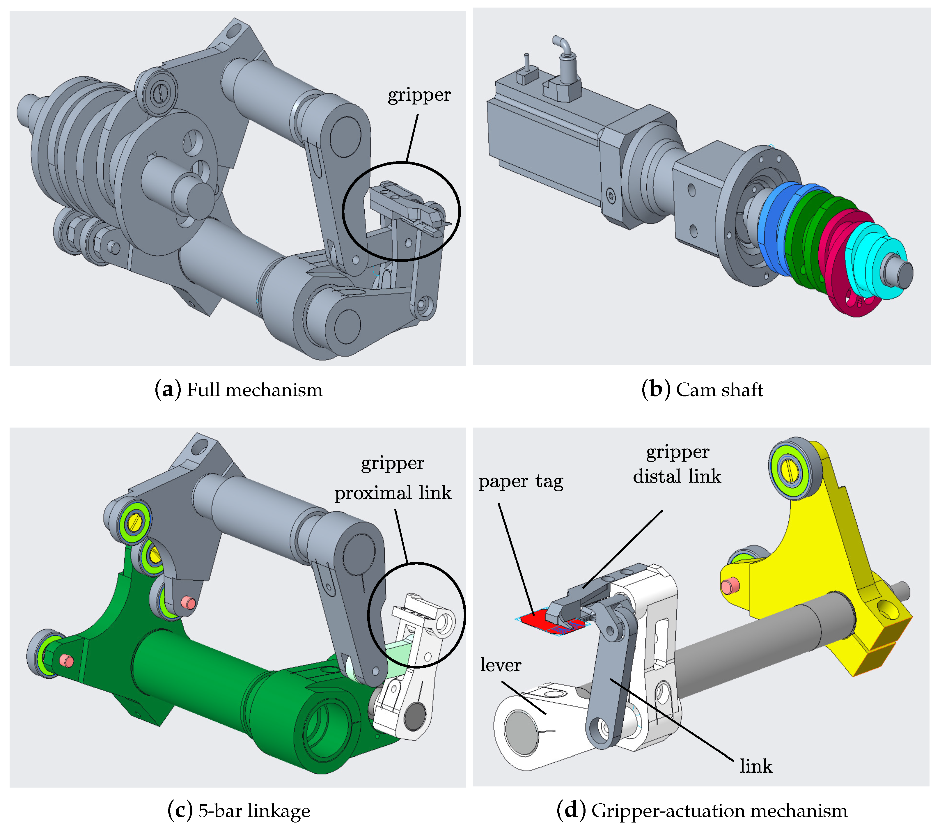
2. Mechanism Description
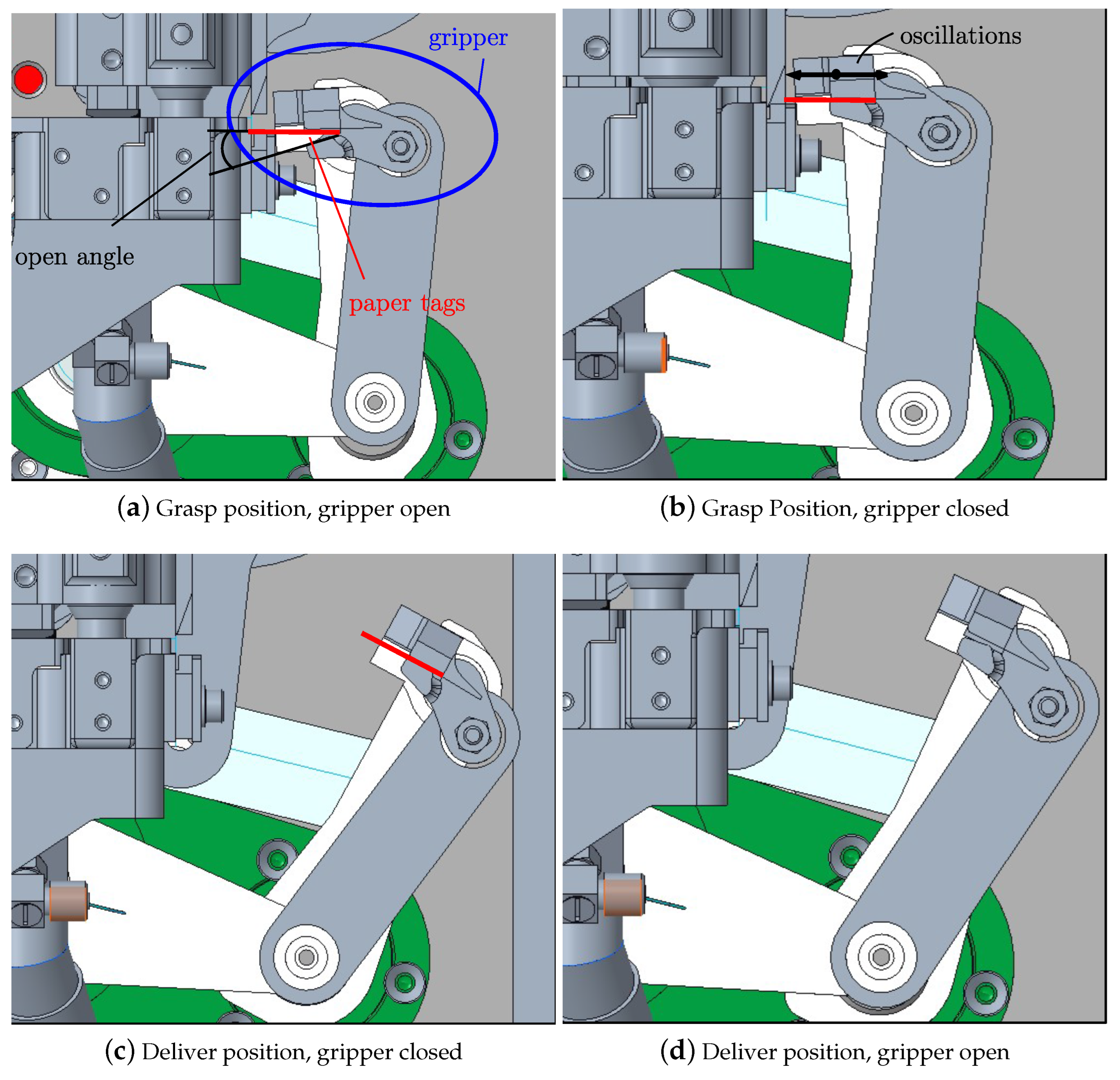
- The gripper is positioned at the grasp position (Figure 2a) and it is open, waiting for paper tags to be received;
- Once a paper tag is available, the gripper closes and the product is grasped thanks to the movement of the gripper-actuation mechanism (Figure 2b);
- The gripper moves to the deliver position (Figure 2c) thanks to the movement of the five-bar linkage;
- At the deliver position, the gripper opens and the product is released (Figure 2d);
- The gripper moves back to the grasp position and the cycle restarts.
3. Dynamic Analysis
3.1. Rigid-Body Dynamic Analysis
3.2. Modal Analysis
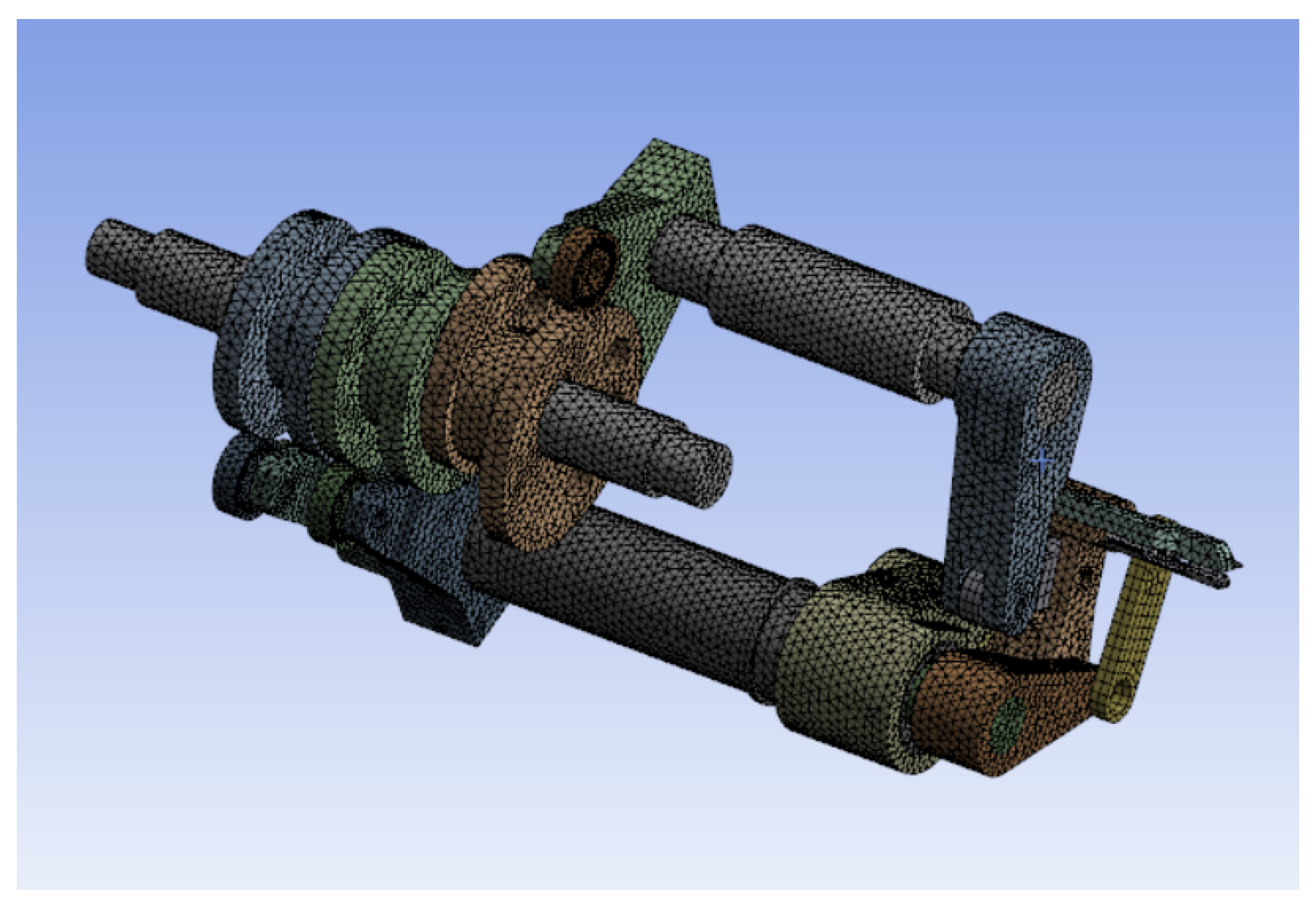
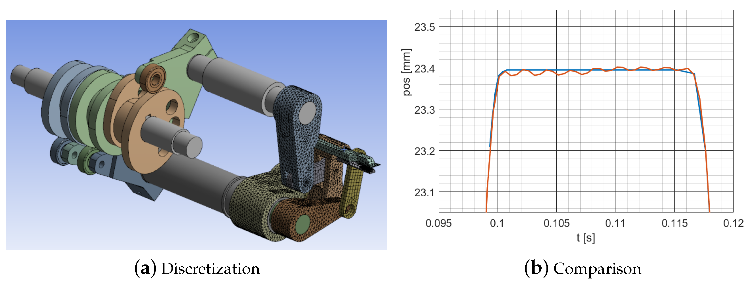
3.3. Elastodynamic Simulation
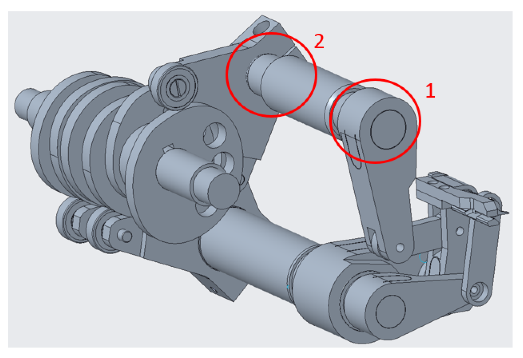
3.4. Joint Stiffness and Possible Solutions
4. Optimization
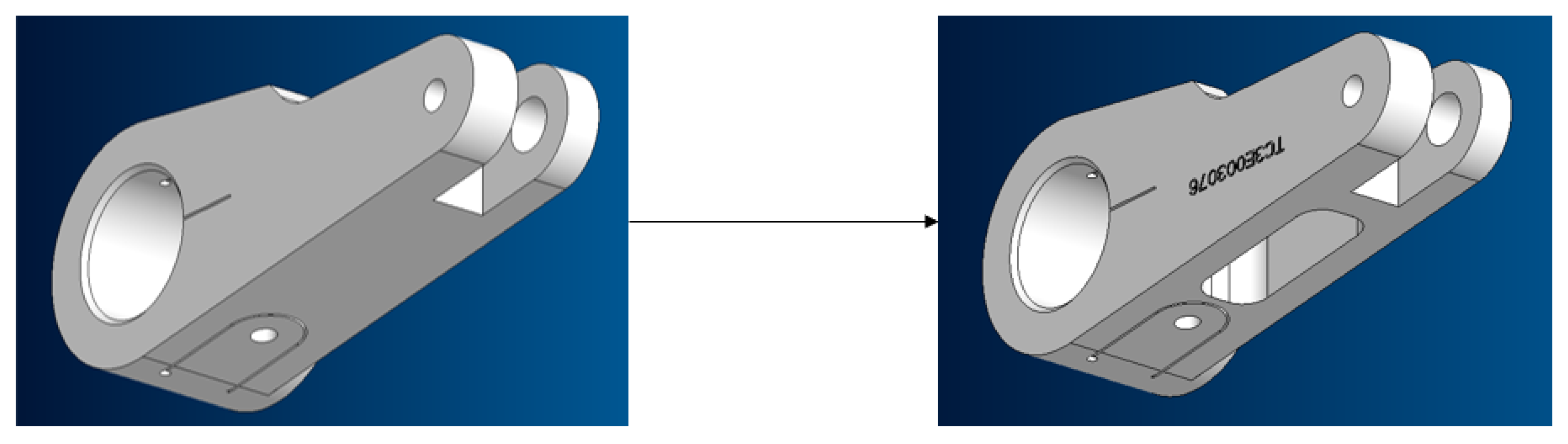
4.1. Mass Reduction
- Each five-bar linkage component is manually modified with simple geometry modifications;
- The modified mechanism is rigidly simulated by means of a multibody simulation software (ANSYS) in order to calculate the reaction force that acts on each joint;
- Then, each link is independently simulated by taking into account its elasticity to estimate the corresponding deformations. Despite the possibility of simulating the overall system in a single time, we preferred to independently verify each component to reduce the simulation time;
- If deformations are negligible, the process continues;
- Modifications are repeated until the base force reaches a sufficiently low value.
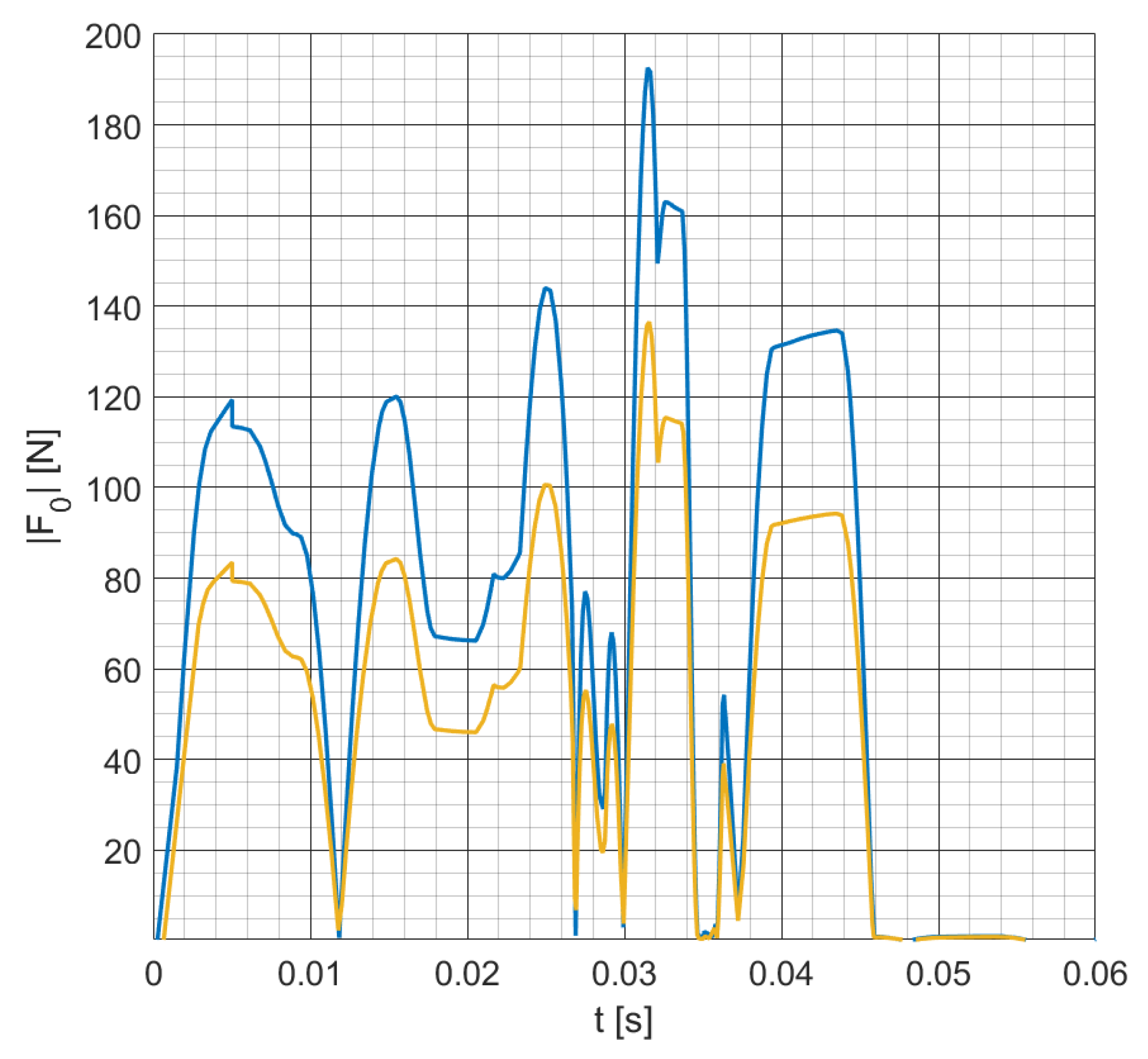
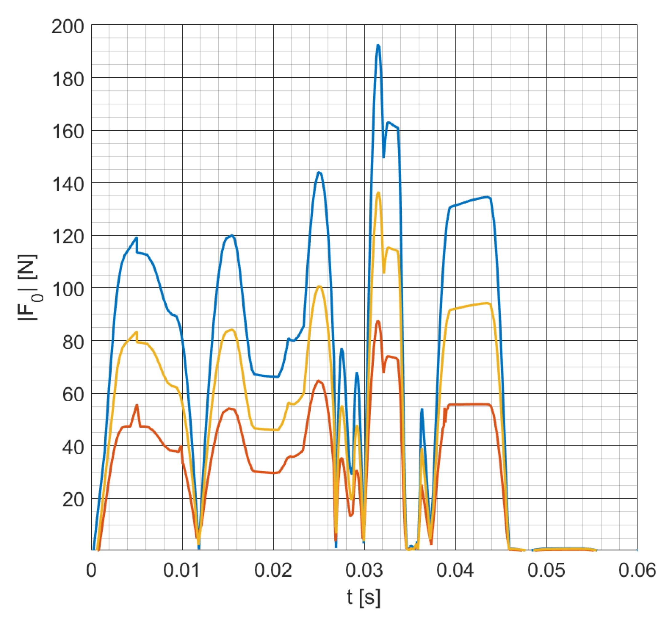
4.2. Dimension Optimization
- Considering the initial design, we extracted the joint values for a single cycle;
- Then, we studied the five-bar mechanism by considering joints Q and C in Figure 3b as motorized. Since the motion of the kinematic chain is not varied in comparison to the original design, the trajectory of the gripper is preserved;
- By the solution of the inverse dynamic problem with new inputs, we can recover the new joint values, and the joint reactions.
5. Conclusions
Author Contributions
Funding
Acknowledgments
Conflicts of Interest
References
- Merlet, J.P. Parallel Robots; Springer Science & Business Media: Berlin/Heidelberg, Germany, 2005; Volume 128. [Google Scholar]
- Soto, I.; Campa, R. On dynamic modelling of parallel manipulators: The Five-Bar mechanism as a case study. Int. Rev. Model. Simulations (IREMOS) 2014, 7, 531–541. [Google Scholar] [CrossRef]
- Fu, Z.F.; He, J. Modal Analysis; Elsevier: Amsterdam, The Netherlands, 2001. [Google Scholar]
- Chen, X.L.; Li, W.B.; Deng, Y.; Li, Y.F. Analysis of stress and natural frequencies of high-speed spatial parallel mechanism. J. Cent. South Univ. 2013, 20, 2676–2684. [Google Scholar] [CrossRef]
- Wasfy, T.M.; Noor, A.K. Computational strategies for flexible multibody systems. Appl. Mech. Rev. 2003, 56, 553–613. [Google Scholar] [CrossRef]
- Song, J.O.; Haug, E.J. Dynamic analysis of planar flexible mechanisms. Comput. Methods Appl. Mech. Eng. 1980, 24, 359–381. [Google Scholar] [CrossRef]
- Nath, P.; Ghosh, A. Kineto-elastodynamic analysis of mechanisms by finite element method. Mech. Mach. Theory 1980, 15, 179–197. [Google Scholar] [CrossRef]
- Zhang, X.; Liu, H.; Shen, Y. Finite dynamic element analysis for high-speed flexible linkage mechanisms. Comput. Struct. 1996, 60, 787–796. [Google Scholar] [CrossRef]
- Shiau, T.N.; Tsai, Y.J.; Tsai, M.S. Nonlinear dynamic analysis of a parallel mechanism with consideration of joint effects. Mech. Mach. Theory 2008, 43, 491–505. [Google Scholar] [CrossRef]
- Parenti-Castelli, V.; Venanzi, S. Clearance influence analysis on mechanisms. Mech. Mach. Theory 2005, 40, 1316–1329. [Google Scholar] [CrossRef]
- Li-Xin, X.; Yong-Gang, L. Investigation of joint clearance effects on the dynamic performance of a planar 2-DOF pick-and-place parallel manipulator. Robot. Comput. Integr. Manuf. 2014, 30, 62–73. [Google Scholar] [CrossRef]
- Bendsoe, M.P.; Sigmund, O. Topology Optimization: Theory, Methods, and Applications; Springer Science & Business Media: Berlin/Heidelberg, Germany, 2003. [Google Scholar]


| Mode Number | Frequency [Hz] |
|---|---|
| 1 | 463.52 |
| 2 | 596.44 |
| 3 | 695.68 |
| 4 | 866.64 |
| 5 | 1182.60 |
| 6 | 1269.10 |
Publisher’s Note: MDPI stays neutral with regard to jurisdictional claims in published maps and institutional affiliations. |
© 2022 by the authors. Licensee MDPI, Basel, Switzerland. This article is an open access article distributed under the terms and conditions of the Creative Commons Attribution (CC BY) license (https://creativecommons.org/licenses/by/4.0/).
Share and Cite
Zaccaria, F.; Quarta, E.; Badini, S.; Carricato, M. Optimal Design for Vibration Mitigation of a Planar Parallel Mechanism for a Fast Automatic Machine. Machines 2022, 10, 770. https://doi.org/10.3390/machines10090770
Zaccaria F, Quarta E, Badini S, Carricato M. Optimal Design for Vibration Mitigation of a Planar Parallel Mechanism for a Fast Automatic Machine. Machines. 2022; 10(9):770. https://doi.org/10.3390/machines10090770
Chicago/Turabian StyleZaccaria, Federico, Edoardo Quarta, Simone Badini, and Marco Carricato. 2022. "Optimal Design for Vibration Mitigation of a Planar Parallel Mechanism for a Fast Automatic Machine" Machines 10, no. 9: 770. https://doi.org/10.3390/machines10090770
APA StyleZaccaria, F., Quarta, E., Badini, S., & Carricato, M. (2022). Optimal Design for Vibration Mitigation of a Planar Parallel Mechanism for a Fast Automatic Machine. Machines, 10(9), 770. https://doi.org/10.3390/machines10090770